


Installation and Operation Manual
For TCP/IP Digital (700) System
Indoor Monitor
Model:G8
Model:H3
Model:G9
Model:HK12
Model:HK5
Model:G5/G6
Model:HK2

Remark
Please follow the user manual for correct installation and testing, if
there is any doubt please call our tech-supporting and customer
center.
Our company applies ourselves to reformation and innovation of
our products. No extra informing for any change. The illustration
shown here only used for reference, if there is any difference
please take the actual product as standard product.

CATALOG
4
Product Features
Technology Parameters
Product Pictures
Operations
1. Home security
2 Home control
3. Communication
4. Multi-media
5 System settings
Installation instruction
Notes
.
.
System Configuration
System Diagram
9
13
17
19
26
29
32
25

Product Features
1.
2. Friendly interface, easy use.
3. Intercom with Outdoor panel, flat panel and Management Center.
4. Support 8 alarm stations (Emergency, Smoke, Gas, IR, Magnetic
contact for door or window).
5. Monitor Max. 8pcs IP cameras (ONVIF protocol).
6. Audio/video intercom between each indoor monitor.
7. Image/Video/Audio records from outdoor panel.
8.Message receiving from management center, Max. 60pcs.
9.Multimedia playing such Mp3 , MP4, and photo frame with SD card.
10. Support Smart Home module, Ipad/Iphone remote control.
12. Easy installation, use international standard RJ 45.
13. Use TCP/IP protocol base on LAN network, no distance and
apartment quantity limitation, multi channel intercom.
14.Easy maintenance : automatic fault detection, software upgrade
with SD card.
7’ or 10’ Touch screen.
-1-
Technology Parameters
◇Voltage: DC12V
◇Operating temperature:-10~+55℃
◇Rate of power: 6W
◇Standby power consumption: 2.5W
◇Talking mode: hands-free
Talking time among indoor monitors: 5 minutes
◇Talking time between indoor monitor and outdoor monitor: 2
minutes
◇Broadband upward capacity: 768K

-2-
Hand-free
Photo frame
Calling
Monitoring
Unlocking
Microphone
Power indicator
Message indicator
Alarm setting indicator
Alarm indicator
SD card port
USB card port
Model:G5/G6
Model:HK12
Pictures
Model:HK2

-3-
Main interface: Home Security, Communication, Multi-media and
System Settings.
Status bar:
Status bar instruction:
1.
Home Control,
:
3. :
4. : C
Alarm status, Mute mode, Community message, and Network mark.
Alarm status : it will flash and you’ll hear “DI-DI” tone when setting up, to indicate
your alarm sensors will be actived after 100 seconds .
2. Mute mode Click to set ON or OFF of mute mode.
Community message Click to read the community message.
Network mark onnect with network properly or not.
Operations

Each indoor monitor can be connected with max. 8 alarm zones. Click icon on
the main interface, the system will enter the following interface.
Three security alarm models for option: At home, Outside and Sleep.
1.Home Security
1. 1 Alarm ON/OFF
1.1.1 To Alarm
Click “At home” “Outside”, or “Sleep” icon to active the alarm sensors, the icon
on the main interface will flash with a “Di-Di” tone. After 100 seconds, the security alarm
will operate.
-4-
1.1.2 Stop Alarm
During the alarm delay time, Click icon , the system will sound a tone, then
the alarm is stopped.

-5-
1.1.3 Alarm OFF
If the system is on “Alarm ON” mode and need to cancel the alarm, now you must
input the user password with 4 digits (the default password is 1234).
1.2 Setting
Click icon, then input the user password with 4 digits (the default password
is 1234), the system will enter the following interface:
Remark: If the system is on “Alarm ON” mode, zone setting cannot be operated.

1.2.1 Alarm Type
Click type input box, it will popup a dialog box as the following. In this interface,
you can set your Type as: 24H, Normal and Emergency. 24H and Emergency type
always active.
1.2.2 Delay Time
Click delay time input box, it will popup a dialog box as the following interface, and
it can be set up as t he following: 0s, 5s, 10s, 15s, 20s, 25s,40s and 60s.
Remark: when alarm type is set as Emergency or 24 Hour, the delay time can only
be set as 0s.
-7-

1.2.3 Sensor Type
Click sensor type input box, it will popup a dialog box such as the following
interface. Each sensor type can be set up as: Smoke, Gas, PIR, Door, Window, Panic,
Flood, Pull Cord and Bed Mat.
-8-
1.3 Scene Mode
Click icon, input the user password with 4 digits(the default password is
1234), the system will enter into the following interface:
is refer to Alarm ON, is refer to Alarm OFF. To set the sensor of alarm
stations, you can click the corresponding station with icon.
Remark: If the system is on “Alarm ON” mode, Scene Mode cannot be operated.

1.4 IP Camera
Click icon, the system will enter into the following interface:
Click or icon to select the IP Camera to monitor; Click icon to monitor.
Click icon to cancel monitor.
-9-
Remark: If the system is on “Alarm ON” mode, IP Camera cannot be operated.
Click icon in the main interface to enter communication interface, it includes:
Monitoring, Calling, Records and Community message.
2.1 Monitoring
Click icon to enter the following interface:
2.Communication
Click or icon to select the monitoring object. When select Main 1~9, it
monitors outdoor panel; when select Sub 1~9. it monitors the flat panel. Click icon
to monitor, click icon to cancel the monitor.

-10-
1栋1单元0 0 0 1
2.2 Calling
2.2.1 Calling Indoor Monitor
Input 1 to 4 digits + “Building”+1 to 2 digits + “Door”+1 to 4 room No., then click
“Call” button. For example, you would like to call indoor monitor: 0001010807. You
can input 1 and click “Building” icon, then input 1 and click “Door” icon, and then input
room No. 0807, finally click “Call” icon. Click icon to delete the wrong input.
When someone calls in, the system will enter into the following interface:
During the call, if connects with main and sub indoor monitor, click to select
the corresponding device to transfer. If the building No. and Unit No. of main and sub
indoor monitor are consistent, you can input room No. with 4 digits directly.

Click “Unlock” to ; ;
Cilck “Magnify” to zoom in the visitor’s image.
During the call, Click icon, the system will record the video, click icon, the
system will record the audio.
unlock the door click “Answer” to answer the call If one calls the
monitor and no one answers, the system will snap the visitor’s image automatically.
During the communication with the visitor, click “Snapshot” icon, the system will snap
the visitor’s image.
2.2.2 Calling the management center
The system can connect max. 10 pcs management center. Click icon to call
the management center, when center 1is busy, it will call the next management center
from 2~10.
Calling center...1
2.3 Records
Click icon, the system will enter into the following interface:
-11-

-12-
It stores the calling records. The max. quantity of records is 20pcs.
Click icon, the system will enter into the following interface:
Click icon, the system will display the visitor’s image, click icon, it will be
paused, click icon, the system will return to the previous interface. If video and
audio are stored in the system, it also will be played.
2.4 Community message
Click icon, the system will enter into the following interface:
Community service receives the sent message from management center.

-13-
3.Home Control
Attention: Home control function should be connected with smart home module
to use, otherwise this function is invalid.
In the main interface, click icon. The system will enter into the Home control
interface.
3.1 Scene Mode
Click icon, the system will enter into the following interface:
Scene mode includes: At home, Outside , Sleep, Party, and Cinema.
3.2 Light
Click icon to enter the following interface:
Set the light of corresponding room, such as Living, Dining, Master and Sub (see
the room setting for details),8 lights can be set in every room at most. Click the
corresponding light icon, then you can control the light turn ON/OFF.

-14-
3.3 Air-condition
Click icon to enter the following interface:
Set the air-condition switch of corresponding room. Click icon to cool; click
icon to turn air-condition on/off; click icon to ventilate; click icon to heat.
icon
3.4 Curtain
Click icon in the home control interface, the system will enter into the
following interface:
Click icon, the curtain is open; if click icon, the curtain is closed; if click
icon, the curtain is paused.icon

-15-
3.5 Elevator
Click icon to enter into the next page, then click icon , the system
will enter into the following interface:
3.6 Room Settings
Click icon to enter into room settings interface.
3.6.1 Room
You can add, delete room data and alter the room name. The room types includes:
Living, Dining, Master, Sub, Study, Kitchen, Corridor. Add, deletion and alteration depends on
room quantity (add 4 rooms at most). After setting, click icon to store it.

-16-
3.6.2 Lamp
You can set the corresponding room’s lamp. The room includes: Mater, Study, Living
and Kitchen. The lamp includes: Lamp, Wall, Ceiling, Table, Floor, Pendant, Crystal and Spot.
Click or to see all lamps. 8 lights can be set at most.
4 Multi-media
4.1 Voice message
Click icon to record. The longest recording time is 30 seconds. Click icon to
stop recording and store it. If the recording time is reached to 30 seconds, the system
will restore the record automatically. Select anyone in records, click icon to play the
record. Click icon to delete all selected records.

4.2 Music player
Click icon to select the file catalogue of SD card, then select the music
folder. Select a song, then click icon to play it. Click or icon to select songs.
Click icon to stop playing the music. The playing type can be set: Chaos and
Cycling. Click icon to random play the music; click icon to cycle play the music.
WAV, Mp3 .etc formats can be supported for music.
-17-
4.3 Media player
select the file catalogue of SD card, then select video folder.
The system will enter into the following interface:
Click icon to

4.4 Photo frame
Click icon, then search SD card or picture files in USB flash disk, select
picture folder, then the system will enter into the following interface, double-click the
selected picture to browse in full screen. JPG、PNG、BMP、GIF、TIF .etc formats can
be supported for picture.
-18-
Select one video, click full screen button to play in full screen; click the screen to
quit it under the full screen mode. If it has incoming call during video playing, the video
will pause. Then it will recover to playing breakpoint automatically to keep on playing
the video after the call.
AVI、MP4、MOV、WMV、RMVB、MPG.etc formats can be supported for video.
5.System Setting
5.1 Normal
Click icon to enter the normal setting interface. Normal setting includes:
Intercom and Date&Time.

5.1.1 Intercom
The system supports video intercom between each indoor monitor, when the
camera is set as ON, other indoor monitor’s users will see you, when it is set as OFF,
they will not see you.
5.1.2 Date&Time
You can set Time zone, Date and time. After setting, click to store it.
-19-

5.2.1 Sound
You can set System and In-call volume, also set Ring and Press type.
5.2.2 Use PSW
You can set new user password. The default password is 1234. User password is
used for Home security.
5.2 Others
k icon, the system will enter other settings interface. Clic
-20-

5.2.4 GUI
You can select the background color you want.
5.2.3 Adjustment
You can set Brightness and Contrast.
-21-

5.3 LAN
Click icon, the system will enter into the following interface
:
(please refer to
the installation instruction)
-22-
5.4 Room No.
Click icon, the system will enter into the following interface
:
(please refer to
the installation instruction)

-23-
5.6 Upgrade
Click icon, the system will enter into the following interface
:
(please refer
to the installation instruction)
5.5 VOIP
Click icon, the system will enter into the following interface :(please refer
to the installation instruction)

5.7 Version
Click icon to see the related version information of this device.
-24-
5.8 Adjust Screen
Warning: End users are not allowed to set this menu, please ask for your
installer for assistance.
When you touch the screen and find the icons cannot react normally, please make
the screen calibnation by yourself. Slowly sliding along horizontal or vertical on the
LCD, or press “Unlock” button for 5 seconds, the system will enter into the following
interface. Click the center of cross intersection from to in turn. After adjustment, the
system will be exited automatically.
1 2
4
3
1
5
5

System Configuration
2F
Network
Switch
Network
Switch
Next Network Switch
Lock
RVV3x 0.5
1F
RVV2x 0.75
UPS-DP/P
Adapter
Adapter
Adapter
Indoor monitor
Outdoor panel
Indoor monitor
Computer
C
A
R
D
1
2
3
*
4
5
6
0
7
8
9
#
or
Management center
Siren(optional)
Smart home control module
(optional)
Alarms(optional)
- -25

Siren
Adapter
To network switch
CAT-5e
Smart home control
module
System Diagram
-2 -6
1.The alarm sensor is normally-open:
- -27
传感器Sensor
传感器
传感器
传感器
传感器
传感器
传感器
传感器
Sensor
Sensor
Sensor
Sensor
Sensor
Sensor
Sensor
2.2K(1/4W)
Resistor
2.2K(1/4W)
Resistor
2.2K(1/4W)
Resistor
2.2K(1/4W)
Resistor
2.2K(1/4W)
Resistor
2.2K(1/4W)
Resistor
2.2K(1/4W)
Resistor

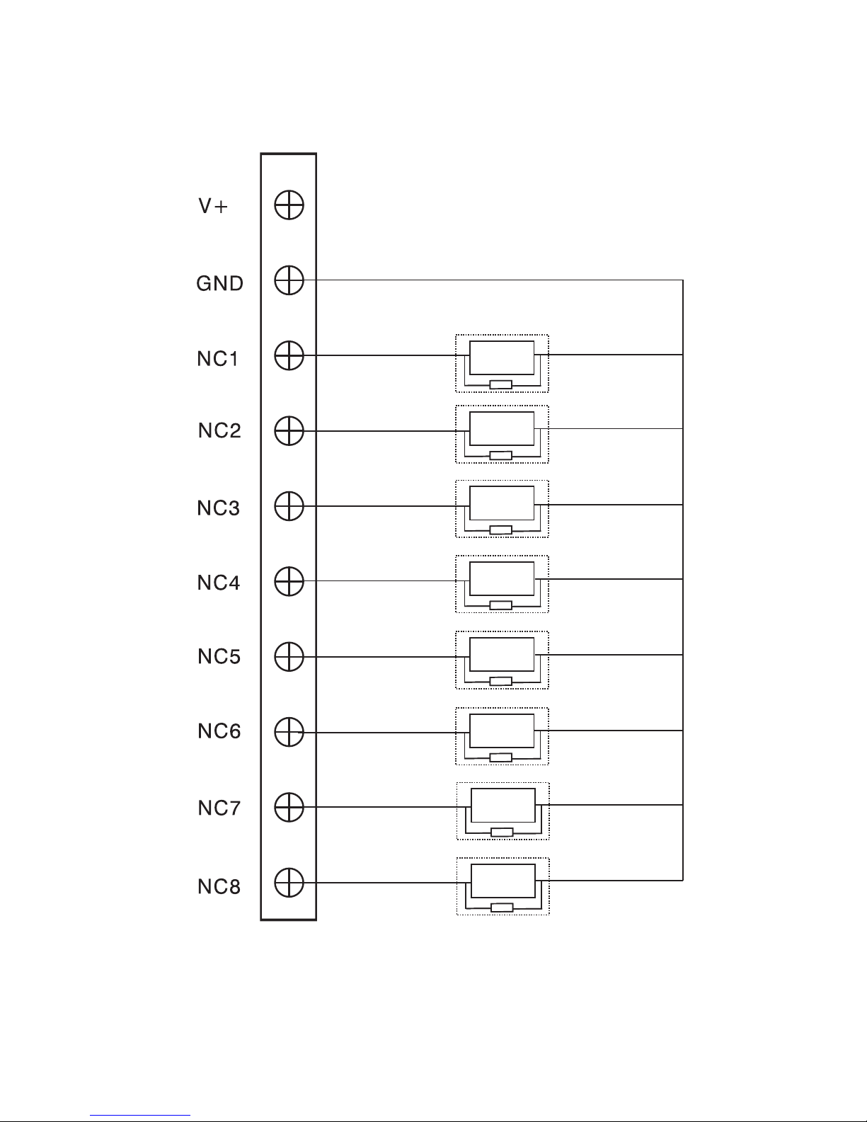
2.The alarm sensor is normally-close:
-28-
Sensor
传感器
Sensor
Sensor
Sensor
Sensor
Sensor
Sensor
Sensor
Sensor
2.2K(1/4W)
Resistor
2.2K(1/4W)
Resistor
2.2K(1/4W)
Resistor
2.2K(1/4W)
Resistor
2.2K(1/4W)
Resistor
2.2K(1/4W)
Resistor
2.2K(1/4W)
Resistor
2.2K(1/4W)
Resistor

Model:G5/G6
SIZE:221*145*23.5
221*145*21.5(G6)
(G5)
Installation Instruction
86 model embedded box
86 model embedded box
Screw
Screw
-29-
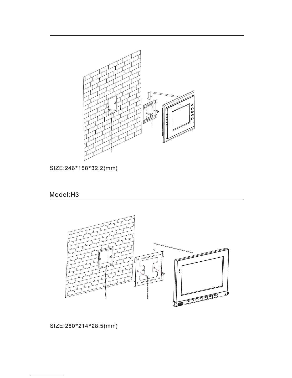
Model:G8
86 model embedded box
Screw
86 model embedded box
Screw
-30-
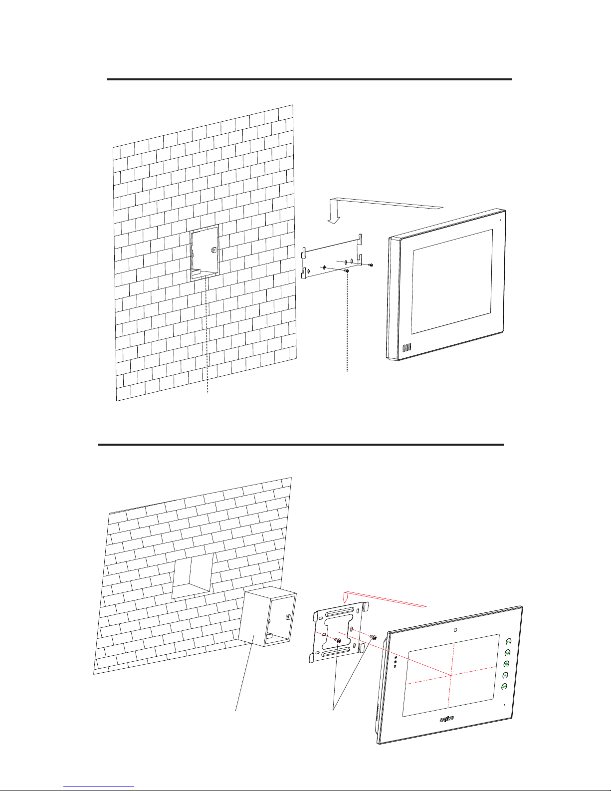
Model:HK12
- -31
86 model embedded box
Screw
Model: HK2
86 model embedded box
Screw

Safety Precautions
1.Please read product description carefully before installation and operation.
2.Do not install the unit in hot and moist area.
3.Do not use the wet dishcloth or volatile solvent alcohol, benzene, thinner and
corrosive solution .etc to clean it. Use soft cloth to clean it gently.
4.Do not drop, knock or shake the unit.
5.Do not attempt to service this unit yourself. If need maintenance, please contact
with customer service center.
6.Please install the unit in the safe and steady place to avoid property loss or personal
casualty caused by falling.
Notes
- -32
 Loading...