

Page 1
www.kruess.com
innovation since 1796
MBL2000-Serie Betriebsanleitung
Binokularmikroskope
MBL2000 Series Operating Manual
Binocular Microscope
de|en
Page 2

32
Inhalt
Inhaltsverzeichnis
DEUTSCH
Einleitung 5
Modellübersicht 6
1. Beschreibung MBL2000 8
2. Zusammenbau des Gerätes 10
3. Bedienung des Mikroskopes 11
3.1 Augenabstands- und Dioptrienkorrektur 12
3.2 Grobtriebeinstellung 12
3.3 Aperturblende 13
3.4 Öl-Immersionsobjektive 13
3.5 Deckglas und Objektträger 14
4. Technische Daten 15
5. Begriffserklärungen 16
6. Zubehör 17
6.1 Objektive 17
6.2 Okulare 17
7. Phasenkontrasteinrichtung 18
8. Dunkelfeldkondensor 24
9. Foto- und Videoanschluss 25
10. Wartung 26
Rückgewinnung und Recycling 27
Garantiebestimmungen 28
ENGLISH
Introduction 31
Models Overview 32
1. Description MBL2000 34
2. Assembly of the microscope 36
3. Operating the microscope 37
3.1 Eye distance and dioptre adjustment 38
3.2 Coarse adjustment 38
3.3 Aperture diaphragm 39
3.4 Oil immersion lenses 39
3.5 Cover glass and object holder 40
4. Technical Data 41
5. Definitions 42
6. Accessories 43
6.1 Object lenses 43
6.2 Eyepieces 43
7. Phase contrast device 44
8. Dark field condenser 50
9. Photo- and video mounting 51
10. Maintenance 52
Recovery and recycling 53
Warranty conditions 54
Index
Index
Page 3

5
DEUTSCH
Wir beglückwünschen Sie zu Ihrem neuen Mikroskop!
Die Mikroskope der MBL2000-Serie wurden für universelle Anwendungen in Forschung,
Medizin und Industrie entwickelt. Die hohe Fertigungsqualität, die sich z.B. im Metallge-häuse zeigt, und die hochwertigen optischen Komponenten garantieren eine lange
Lebensdauer. Das umfangreiche Zubehör macht diese Mikroskope sehr vielseitig verwendbar.
Alle Mikroskope der MBL2000-Serie bestehen aus einem soliden Metallstativ und mit
einem um 360° drehbaren Optikkopf mit 45°-Einblick ausgestattet. Ein 10x Planokularpaar und auswechselbare achromatische Objektive bilden zusammen die optische
Ausstattung. 20x Okulare oder planachromatische Objektive für besonders anspruchsvolle Anwendungen sind ebenfalls erhältlich. Die Beleuchtung besteht aus einer 6 VHalogenlampe mit 20 oder 30 Watt, dem Hellfeld Abbe-Kondensor und der Irisblende.
Für besondere Anwendungen sind eine Phasenkontrasteinrichtung, eine Dunkelfeldeinrichtung oder ein Optikkopf mit Fototubus erhältlich.
Einleitung
A.KRÜSS Optronic weist darauf hin, dass diese
Anleitung wichtige Informationen zur Sicherheit und
Wartung beinhaltet und daher jedem Nutzer zur
Verfügung gestellt werden sollte. A.KRÜSS Optronic
weist jede Haftung für unsachgemäßen Gebrauch
des Mikroskops zurück.
Wichtige Hinweise zur Handhabung
⋅ Bitte behandeln Sie Ihr Mikroskop immer mit der, für ein Präzisionsinstrument
erforderlichen Sorgfalt.
⋅ Bewahren Sie Ihr Mikroskop insbesondere vor direkter Sonneneinstrahlung, vor
Staub, Feuchtigkeit und Vibration.
⋅ Bitte drehen Sie die sich gegenüberliegenden Fein- und Grobtriebringe nie gleich zeitig gegeneinander.
⋅ Ziehen Sie den Netzstecker vor einem Lampen- und Sicherungswechsel aus der
Steckdose.
⋅ Bitte beachten Sie immer die Hinweise in Kapitel 10 | Wartung.
Einleitung
Page 4

76
Optische Ausstattung Ausstattung Beleuchtung Besonderheiten Anwendung
MBL2000
(Basismodell)
Binokular-Mikroskop,
10x Planokulare,
Objektive:
4x/NA 0.10
10x/NA 0.25
40x/NA 0.65
100x/NA 1.25 Öl
XY-Tisch,
koaxialer Grobund Feintrieb,
Irisblende,
Filterhalter,
Blaufilter,
Grünfilter
6 V 20 W
regelbar,
Hellfeld-ABBEKondensor
Labor,
Qualitätskontrolle,
Universitäten
MBL2000-30W Binokular-Mikroskop,
10x Planokulare,
Objektive:
4x/NA 0.10,
10x/NA 0.25,
40x/NA 0.65,
100x/NA 1.25 Öl
XY-Tisch,
koaxialer Grobund Feintrieb,
Irisblende,
Filterhalter,
Blaufilter,
Grünfilter
6 V 30 W
regelbar,
Hellfeld-ABBEKondensor
30 W Beleuchtung Labor,
Qualitätskontrolle,
Universitäten
MBL2000-T Trinokular-Mikroskop,
10x Planokulare,
Objektive:
4x/NA 0.10,
10x/NA 0.25,
40x/NA 0.65,
100x/NA 1.25 Öl
XY-Tisch,
koaxialer Grobund Feintrieb,
Irisblende,
Filterhalter,
Blaufilter,
Grünfilter
6 V 20 W
regelbar,
Hellfeld-ABBEKondensor
Fototubus Labor,
Qualitätskontrolle,
Universitäten,
MBL2000-T-30W Trinokular-Mikroskop,
10x Planokulare,
Objektive:
4x/NA 0.10,
10x/NA 0.25,
40x/NA 0.65,
60x/NA 0.85,
100x/NA 1.25 Öl
XY-Tisch,
koaxialer Grobund Feintrieb,
Irisblende,
Filterhalter,
Blaufilter,
Grünfilter
6 V 30 W
regelbar,
Hellfeld-ABBEKondensor
Fototubus
30 W Beleuchtung
Labor,
Qualitätskontrolle,
Universitäten
MBL2000-PL-PH Binokular-Mikroskop,
10x Planokulare,
Objektive (planachrom.):
4x/NA 0.10,
PH10x/NA 0.25,
PH40x/NA 0.65,
PH100x/NA 1.25 Öl
XY-Tisch,
koaxialer Grobund Feintrieb,
Irisblende,
Filterhalter,
Blaufilter,
Grünfilter
6 V 20 W
regelbar,
Hellfeld-ABBEKondensor,
Phasenkontrast,
Dunkelfeld
Phasenkontrasteinrichtung mit
Dunkelfeld
Klärwerk,
Labor,
Qualitätskontrolle,
Universitäten
MBL2000-T-PL-PH Trinokular-Mikroskop,
10x Planokulare,
Objektive (planachrom.):
4x/NA 0.10,
PH10x/NA 0.25,
PH40x/NA 0.65,
PH100x/NA 1.25 Öl
XY-Tisch,
koaxialer Grobund Feintrieb,
Irisblende,
Filterhalter,
Blaufilter,
Grünfilter
6 V 20 W
regelbar,
Hellfeld-ABBEKondensor,
Phasenkontrast,
Dunkelfeld
Fototubus
Phasenkontrasteinrichtung mit
Dunkelfeld
Klärwerk,
Labor,
Qualitätskontrolle,
Universitäten
MBL2000-PL Binokular-Mikroskop,
10x Planokulare,
Objektive (planachrom.):
4x/NA 0.10,
10x/NA 0.25,
40x/NA 0.65,
100x/NA 1.25 Öl
XY-Tisch,
koaxialer Grobund Feintrieb,
Irisblende,
Filterhalter,
Blaufilter,
Grünfilter
6 V 20 W
regelbar,
Hellfeld-ABBEKondensor
planachromatische
Objektive
Labor,
Qualitätskontrolle,
Universitäten
Modellübersicht
T Trinokular / Fototubus
PL Planachromatische Objektive
PH Phasenkontrasteinrichtung
B Blutuntersuchungseinrichtung
30W 30Watt Beleuchtung
MBL2000-PL-30W Binokular-Mikroskop,
10x Planokulare,
Objektive (planachrom.):
4x/NA 0.10,
10x/NA 0.25,
40x/NA 0.65,
100x/NA 1.25 Öl
XY-Tisch,
koaxialer Grobund Feintrieb,
Irisblende,
Filterhalter,
Blaufilter,
Grünfilter
6 V 30 W
regelbar,
Hellfeld-ABBEKondensor
planachromatische
Objektive,
30 W Beleuchtung
Labor,
Qualitätskontrolle,
Universitäten
MBL2000-T-PL Trinokular-Mikroskop,
10x Planokulare,
Objektive (planachrom.):
4x/NA 0.10,
10x/NA 0.25,
40x/NA 0.65,
100x/NA 1.25 Öl
XY-Tisch,
koaxialer Grobund Feintrieb,
Irisblende,
Filterhalter,
Blaufilter,
Grünfilter
6 V 20 W
regelbar,
Hellfeld-ABBEKondensor
Fototubus
planachromatische
Objektive
Labor,
Qualitätskontrolle,
Universitäten
MBL2000-T-PL-30W Trinokular-Mikroskop,
10x Planokulare,
Objektive (planachrom.):
4x/NA 0.10,
10x/NA 0.25,
40x/NA 0.65,
100x/NA 1.25 Öl
XY-Tisch,
koaxialer Grobund Feintrieb,
Irisblende,
Filterhalter,
Blaufilter,
Grünfilter
6 V 30 W
regelbar,
Hellfeld-ABBEKondensor
Fototubus,
planachromatische
Objektive,
30 W Beleuchtung
Labor,
Qualitätskontrolle,
Universitäten
MBL2000-B Binokular-Mikroskop,
10x Planokulare,
Objektive:
4x/NA 0.10,
10x/NA 0.25,
40x/NA 0.65,
100x/NA 1.25 Öl
XY-Tisch,
koaxialer Grobund Feintrieb,
Irisblende,
Filterhalter,
Blaufilter,
Grünfilter
15 V 150 W
regelbar,
Kaltlichtquelle
regelbar,
DunkelfeldKondensor für
Blutuntersuchung
150 W Kaltlichtquelle,
Dunkelfeld für Blut
Blutuntersuchung
nach Enderlein,
Heilpraktiker
Labor,
Qualitätskontrolle
Universitäten
MBL2000-T-B Trinokular-Mikroskop,
10x Planokulare,
Objektive:
4x/NA 0.10,
10x/NA 0.25,
40x/NA 0.65,
100x/NA 1.25 Öl
XY-Tisch,
koaxialer Grobund Feintrieb,
Irisblende,
Filterhalter,
Blaufilter,
Grünfilter
15 V 150 W
regelbar,
Kaltlichtquelle
regelbar,
DunkelfeldKondensor für
Blutuntersuchung
Fototubus,
150 W Kaltlichtquelle,
Dunkelfeld für Blut,
dritter Tubus zum
Anschluss von Fotound Videokameras
Blutuntersuchung
nach Enderlein,
Heilpraktiker,
Labor,
Qualitätskontrolle
Universitäten
MBL2000-PL-B Binokular-Mikroskop,
10x Planokulare,
Objektive (planachrom.):
4x/NA 0.10,
10x/NA 0.25,
40x/NA 0.65,
100x/NA 1.25 Öl
XY-Tisch,
koaxialer Grobund Feintrieb,
Irisblende,
Filterhalter,
Blaufilter,
Grünfilter
15 V 150 W
regelbar,
Kaltlichtquelle
regelbar,
DunkelfeldKondensor für
Blutuntersuchung
150 W Kaltlichtquelle,
Dunkelfeld für Blut,
planachromatische
Objektive
Blutuntersuchung
nach Enderlein,
Heilpraktiker,
Labor,
Qualitätskontrolle,
Universitäten
MBL2000-T-PL-B Trinokular-Mikroskop,
10x Planokulare,
Objektive (planachrom.):
4x/NA 0.10,
10x/NA 0.25,
40x/NA 0.65,
100x/NA 1.25 Öl
XY-Tisch,
koaxialer Grobund Feintrieb,
Irisblende,
Filterhalter,
Blaufilter,
Grünfilter
15 V 150 W
regelbar,
Kaltlichtquelle
regelbar,
DunkelfeldKondensor für
Blutuntersuchung
Fototubus,
150 W Kaltlichtquelle,
Dunkelfeld für Blut,
planachromatische
Objektive
Blutuntersuchung
nach Enderlein,
Heilpraktiker,
Labor,
Qualitätskontrolle,
Universitäten
Modellübersicht Modellübersicht
Page 5
98
1. Beschreibung
1. Beschreibung MBL2000
1. Beschreibung
Okular
Okularkopf
XY-Objekttisch
mit Halteklammern
Grobeinstellung Fokus
Feineinstellung Fokus
Ein-/Aus Netzschalter
Kondensor mit Aperturblende
Objektive (4 Stück)
Objektivrevolver
Helligkeitsregler
Stativ
Bodenwanne mit Elektronik
Standfußgehäuse
Netzsicherung
(unter der Bodenwanne)
Lampenkondensor
Filterhalterung ausschwenkbar
Augenabstandseinstellung
Okularhalterung mit
Dioptrieneinstellung
Feststellschraube
für Okularkopf
Feststellring Grobtrieb rechts
Blendeneinstellung
Einstellknopf X-Richtung
Einstellknopf-Y-Richtung
Feststellschraube für Okularkopf
Deckglashalteklammer
Page 6
1110
2. Zusammenbau des Gerätes
Aus verpackungstechnischen Gründen wird das Gerät in mehreren Teilen zerlegt geliefert.
Der Zusammenbau des Mikroskopes ist einfach.
2. Zusammenbau des Gerätes
1. Den Standfuß aus der Verpackung nehmen,
den Okularkopf aufsetzen und mit der seitlichen
Schraube fixieren.
2. Die Abdeckungen entfernen und die Okulare in
den Okularkopf einsetzen.
3. Die vier Objektive aus den Kunststoffbehältern auspacken und in den Objektivrevolver einschrauben.
3. Bedienung des Mikroskopes
3. Bedienung des Mikroskopes
1. Schalten Sie den Hauptschalter ein.
2. Legen Sie ein Präparat auf den Objekttisch.
3. Lösen Sie den Grobtriebvorwahlanschlag
(siehe 3.2).
4. Fokussieren Sie mit dem Objektiv 4x oder 10x auf
das Präparat.
5. Nehmen Sie die Augenabstands-und Dioptrien-
korrektur vor (siehe 3.1).
6. Schwenken Sie das gewünschte Arbeitsobjektiv ein.
7. Fixieren Sie die Einstellebene für den Grobtrieb mit
dem Grobtriebvorwahlanschlag (siehe 3.2).
8. Regeln Sie die Lichtintensität mit dem Helligkeitsregler.
9. Nehmen Sie die Feinfokussierung mit dem Feintriebknopf vor.
10. Stellen Sie die Aperturblende richtig ein (siehe 3.3).
Hinweis
Sollte am Arbeitsplatz keine Netzspannung zur Verfügung stehen, so kann zur Beleuchtung des Präparates ein Spiegel (als Zubehör erhältlich) benutzt
werden. Dazu wird der Lampenkondensor herausgeschraubt und durch den Spiegel ersetzt.
Dabei wird der Spiegelfuß in die Lampenkondensorfassung geschraubt.
Nun ist das Mikroskop mit seinen Grundfunktionen
gebrauchsfertig. Das Anbringen von Zubehörteilen
wird in der Anlage erläutert.
Page 7

1312
angehoben werden. Auch nach einem vorherigen
Absenken des Tisches zum Objektivwechsel kann der
Tisch über den Grobtrieb nur wieder bis zu der vorher
vorgewählten Position angehoben werden, vorausgesetzt der Feintrieb wurde nicht verstellt. Das Objekt
befindet sich somit wieder in der Fokussierebene.
Der Feintrieb bleibt vom Vorwahlanschlag unbeeinflußt.
3.1 Augenabstands- und Dioptrienkorrektur
3. Bedienung des Mikroskopes / 3.1 Augenabstands- und Dioptrienkorrektur / 3.2 Grobtriebeinstellung
Aperturblende:
2/3 des Pupillendurchmessers
Pupille
1. Nehmen Sie den Okularschlitten des rechten und
linken Okularstutzens mit beiden Händen und
richten Sie sie auf Ihren Augenabstand ein.
2. Der Augenabstand ist richtig eingestellt, wenn Sie
ein rundes Gesichtsfeld mit entspannten Augen
übersehen können.
3. Merken Sie sich Ihren Augenabstand, den Sie auf
der Skala ablesen können.
4. Drehen Sie nun den Tubuslängenausgleichsring des
rechten Okularstutzens auf den von der Augenabstandsskala abgelesenen Wert.
5. Sehen Sie nun mit dem rechten Auge durch das
rechte Okular und stellen Sie das Objekt mit dem
Feintrieb scharf.
6. Sehen Sie nun mit dem linken Auge durch das
linke Okular und stellen Sie das Objekt mit dem
Tubuslängenausgleichsring scharf ein, ohne den
Grobtrieb oder den Feintrieb zu betätigen.
Die mechanische Tubuslänge aller Durchlichtmikroskope beträgt 160 mm.
wichtiger Hinweis
Drehen Sie den rechten und linken Triebknopf nie
gleichzeitig gegeneinander.
3.2 Grobtriebeinstellung Über einen Rändelring zwischen dem Mikroskopstativ
und dem rechten Grobtriebrad kann der Grobtrieb je
nach Wunsch leicht oder schwergängiger eingestellt
werden. So kann ein selbstständiges Absinken des Kreuztisches bei Belastungswechsel und damit verbundenem
Fokussierfehler vermieden werden.
Durch den Vorwahlanschlag wird ein möglicher Kontakt zwischen Objekt und Objektiv verhindert und die
Grobfokussierung vereinfacht. Nach der Fokussierung
über den Grobtrieb wird der Hebel in Uhrzeigerrichtung
bis zum Anschlag gedrückt. Der Objekttisch kann nun
mit dem Grobtrieb nicht mehr über diese Position hinaus
bitte beachten!
Bei Einstellungen über den Grobtrieb ist darauf acht
zu geben, dass der Vorwahlanschlag auf das jeweilige Objektiv eingestellt ist.
Während der Einstellung und der gleichzeitigen
Sichtkontrolle durch die Okulare ist es andernfalls
leicht möglich, dass das Objektiv in das Präparat
hinein gefahren wird und hierdurch sowohl Objektiv
als auch Präparat beschädigt werden.
3.3 Aperturblende Über die im Kondensor eingebaute Aperturblende
lässt sich die Schärfentiefe des Bildkontrastes und das
Auflösungsvermögen der Mikroskopobjektive einstellen.
Um eine optimale Abbildungsqualität zu erhalten, sollte
die Aperturblendenöffnung in der Regel 70– 80 % der
Objektivapertur entsprechen. Die richtige Einstellung
der Aperturblende kann durch Herausnehmen des
Okulars kontrolliert werden. Man kann dann das Bild
der Aperturblende im Strahlengang erkennen (Lichtintensität eventuell herunterregeln).
Theoretisch muss die Aperturblende nach jedem
Wechsel des Objektivs entsprechend neu eingestellt
werden.
3.4 Öl-Immersionsobjektive, signiert mit „HI“- Homogene Immersion
Zur vollen Ausnutzung der nummerischen Apertur eines
Immersionsobjektives müssen Objektiv und Objekt - in
Sonderfällen auch der Kondensor - mit Immersionsöl
immergiert werden.
3. Bedienung des Mikroskopes / 3.3 Aperturblende / 3.4 Immersionsobjektive
Page 8

1514
Bitte gehen Sie wie folgt vor:
1. Stellen Sie das zu untersuchende Objekt zunächst
mit einem schwach vergrößernden Objektiv (z.B.
10 x) scharf ein.
2. Betätigen Sie den Grobtriebvorwahlanschlag wie in
3.2 beschrieben
3. Senken Sie den Objekttisch mit dem Grobtrieb ab.
4. Geben Sie einen Tropfen Immersionsöl auf die,
durch den Kondensor beleuchtete und zu untersuchende Objektstelle.
5. Schwenken Sie nun das Immersionsobjektiv ein.
Heben Sie den Objekttisch vorsichtig nur mit dem
Grobtrieb bis zum Anschlag an (Vorwahlanschlag).
6. Wenn nötig, jetzt mit dem Feintrieb nachfokussieren. Achten Sie darauf, dass sich im Immersionsöl keine Luftblasen bilden.
Nach Gebrauch ist das Immersionsobjektiv wieder mit
Linsenputzpapier oder einem entsprechenden Tuch zu
reinigen (eventuell Äther/Alkohol benutzen).
wichtiger Hinweis!
Es ist unbedingt darauf zu achten, daß bei Einschwenken eines anderen Objektives dieses nicht
mit dem Öl in Berührung kommt und dadurch
verschmutzt!
3.5 Deckglas und Objektträger
Das Deckglas liegt über dem Objekt. Die mit einer
Gravur 0.17 versehenen Objektive sind für eine
Deckglasdichte von 0.17 mm korrigiert, d.h. bei
Trockenobjektiven mit einer NA (nummerischen
Apertur) von 0.7 und höher ist ausschließlich eine
Deckglasdichte von 0.17 mm zu verwenden, da das
Objektiv über eine Deckglaskorrektur verfügt.
Bei dem Objektiv Achromat 40x / NA 0.65 oder bei
Objektiven mit schwächeren Vergrößerungen kann
ein spezielles Deckglas für Blutzählkammern von 0.4
mm Dicke verwendet werden.
Objektträger:
Wir empfehlen Ihnen, Objektträger von 0.8– 1.5 mm
Dicke zu verwenden.
4. Technische Daten
Optikkopf Optikkopf mit Schrägeinblick, symmetrischer Augenab standsjustierung (55–75 mm), Dioptrienausgleich mit
Skala.
Objektivrevolver 4-fach
Objektive achromatisch 4x 0.10 NA 17.04 mm Arbeitsabstand
10x 0.25 NA 8.05 mm Arbeitsabstand
40x 0.65 NA 0.32 mm Arbeitsabstand
100x 1.25 NA 0.13 mm Arbeitsabstand
Okulare 10x, Fokuslänge 25 mm
Stativ aus Metall mit koaxialem Grob-/ Feintrieb mit einem
Bereich von jeweils 30 mm.
rechter Grobtrieb mit Gängigkeitsjustierung,
linker Grobtrieb mit Schnellfokussiereinrichtung.
Kreuztisch mit Merkskala 0.1 mm Teilung, Bewegungsbereich
links-rechts 74 mm, vorn hinten 30 mm.
Niedervoltbeleuchtung eingebaut, 6 V 20 W (oder 30 W) Halogenlampe mit
Helligkeitsregelung.
Kondensor Doppellinsen-ABBE-Kondensor, NA 1.25, mit
Zentrierung, Höhenverstellung und Filterhalter.
CE-Konformität Das Gerät erfüllt die Vorschriften nach
EN 50081-1,IEC 1000-4-2,
IEC 1000-4-4 und IEC 1000-4-5.
4. Technische Daten3. Bedienung des Mikroskopes / 3.5 Deckglas und Objektträger
Page 9

1716
5. Begriffserklärungen
Arbeitsabstand Abstand zwischen Präparat und Objektivfrontlinsen fassung
Nummerische Apertur Eine mathematische Beziehung, welche in direkter (NA)
Verbindung mit dem Öffnungsverhältnis und dem
Auflösungsvermögen des Objektives steht.
Die NA ist das Produkt des Sinus des halben Öffnungs winkels eines Objektives und dem Brechungsindex des
Mediums, durch welches das Licht in das Objektiv ein tritt. Sie ist eine besonders wichtige Konstante für Hoch leistungobjektive.
Auflösungsvermögen Fähigkeit des Objektives, die feinen Objektstrukturen
getrennt darzustellen. Das Auflösungsvermögen eines
Mikroskopobjektives ist daran zu messen, wie zwei
benachbarte Punkte aufgelöst werden (Linienstrukturen
im Objekt kann man als Punktreihe ansehen).
Das Auflösungsvermögen eines Mikroskopobjektives
wird wie folgt definiert:
Das Wellenlängengebiet des sichtbaren Lichtes liegt
zwischen 400 µm und 700 µm.
Wird die Wellenlänge des Lichtes herabgesetzt, so steigt
auch das Auflösungsvermögen. Je höher das Auflösungs vermögen des Objektives, desto feiner kann die Struktur
des Objektes aufgelöst werden.
Schärfentiefe Distanz zwischen der oberen und unteren Grenze der
Bildschärfe, die durch das optische System bestimmt
wird. Strukturen, die außerhalb dieser Grenze liegen,
erscheinen unscharf und können nur bei Gebrauch von
schwachen Objektiven hinreichend scharf erkannt
werden. Eine geringe Schärfentiefe wirkt sich besonders
bei der Mikrofotografie ungünstig aus.
Sehfeldzahl Diejenige, welche den Durchmesser des Feldes im
Okular (Blende) in mm angibt.
Sehfelddurchmesser Das tatsächlich zu überschauende Objektfeld in mm.
Der Sehfeldmesser eines Mikroskopokulares errechnet
sich in mm wie folgt:
5. Begriffserklärungen
A=0.61
Wellenlänge
NA
6. Zubehör / 6.1 Objektive/ 6.2 Okulare
6.1 Objektive Das Mikroskop ist serienmäßig mit achromatischen
Objektiven 4x, 10x, 40x und 100x (Öl) ausgerüstet.
Für eine 200-fache Gesamtvergrößerung ist auch ein
20x achromatisches Objektiv, für eine 600-fache Ver größerung ein 60x achromatisches Objektiv lieferbar.
Um verbesserte Abbildungseigenschaften auch in den
Randbereichen des Sehfeldes zu erhalten, können die
achromatischen Objektive gegen planachromatische
Objektive ausgewechselt werden.
Auch die planachromatischen Objektive sind in den
Werten 4x, 10x, 20x, 40x und 100x (Öl) erhältlich.
Objektivdaten:
Vergrößerung NA Arbeitsabstand
4x 0.10 17.04 mm
10x 0.25 8.05 mm
20x 0.40 2.10 mm
40x 0.65 0.32 mm teleskopisch
100x 1.25 0.13 mm Öl-Immersion
6.2 Okulare
Das Mikroskop ist serienmäßig mit einem oder zwei
10x Weitfeld-Planokularen ausgerüstet. Damit erhält
man eine Gesamtvergrößerung von 40-fach, 100-fach,
400-fach und 1000-fach.
Bei Benutzung eines oder zweier 16x-Okulare erhält
man Gesamtvergrößerungen von 64-fach, 160-fach,
640-fach und 1600-fach.
Zum Vermessen und Zeigen von Proben gibt es als
Zubehör ein 10x-Zeigerokular. In das Bild wird ein auf
den Mittelpunkt gerichteter Zeiger eingeblendet
(siehe Abb 1). Mit Hilfe der Skalen am XY-Tisch können
Abstände ausgemessen werden.
Ein anderes Hilfsmittel zum Vermessen von Proben ist
das Mikrometerokular (siehe Abb. 2)
Das Mikrometerokular hat eine 15-fache Vergrößerung,
dadurch erhält man eine Gesamtvergrößerung von
60-fach, 150-fach, 600-fach und 1500-fach.
6. Zubehör
Abb. 1
Abb. 2
Vergrößerung
des Objektives
Sehfeldzahl des Okulares
Objektseitiges Sehfeld in mm
=
Page 10

1918
7. Phasenkontrasteinrichtung
Die Phasenkontrasteinrichtungen können an unsere
nachstehenden Mikroskope adaptiert werden:
MML1500, MBL2000 und MBL2000-T
Die Phasenkontrasteinrichtung MML 2031 besteht aus
einem Positiv-Phasenkontrastobjektiv mit einem Phasenverzögerungsring (20x), einer Zentrierringblende und
einem Zentrierteleskop, Dunkelfeld und Hellfeld.
Die Phasenkontrasteinrichtung MML 2031 besteht aus
einem Positiv-Phasenkontrastobjektiv mit einem Phasenverzögerungsring (40x), einer Zentrierringblende und
einem Zentrierteleskop, Dunkelfeld und Hellfeld.
Die Phasenkontrasteinrichtung MML2030 besteht
aus je einem Positiv-Phasenkontrastobjektiv und einer
Zentrierblende für 10x, 40x, und 100x-Vergrößerungen
und einem Zentrierteleskop.
MML 2031
MML 2030
7. Phasenkontrasteinrichtung
7. Phasenkontrasteinrichtung
Technische Daten und Merkmale
Bei der Untersuchung von ungefärbten, farblosen und
lichtdurchlässigen Objekten im Hellfeld ist der Kontrast
häufig zu schwach. Um das Einfärben zu vermeiden
oder um lebendes Material zu untersuchen, kann das
Phasenkontrastverfahren eingesetzt werden.
Eingefärbte Objekte lassen sich beobachten, weil die
verschiedenen Komponenten unterschiedliche Dichte
haben. Bei lichtdurchlässigen Objekten sind Details im
Hellfeld nur schwer zu erkennen, da alle Komponenten
die gleiche Dichte haben.
Funktionsprinzip
Je nach Objektiv entspricht die Skalenlänge von
10 Einheiten:
Objektiv 4x = 2500 um
Objektiv 10x = 1000 um
Objektiv 40x = 250 um
Objektiv 100x = 100 um
Auch beim Binokularmikroskop sollte nur ein Zeiger
oder Mikrometerokular verwendet werden, da sonst
eine Doppelabbildung der Skala entstehen kann.
MML 2032
Das System arbeitet nach dem Positiv-Phasenkontrastverfahren. Die einzelnen Phasenkontrasteinsätze haben
folgende Daten:
Achromatisches Phasenkontrastobjektiv
10x NA 0.25 mit Ringblende in Zentrierfassung.
Achromatisches Phasenkontrastobjektiv
40x NA 0.65 mit Ringblende in Zentrierfassung.
Achromatisches Phasenkontrastobjektiv
100x NA 1.25 für Ölimmersion mit Ringblende
in Zentrierfassung.
Zentrierteleskop mit verstellbarem Okular.
PH-1
PH-2
PH-3
Page 11

2120
7. Phasenkontrasteinrichtung
Hier kann das Dunkelfeld eingesetzt werden, um durch
Kanteneffekte wie Lichtstreuung und Beugung scharfe
Bilder zu erzeugen. Falls das Objekt kristalline Struktur
oder Richtungseigenschaften hat, kann auch polarisiertes Licht eingesetzt werden.
Das Phasenkontrastverfahren ist eine Beleuchtungsart,
bei der ein Teil des Lichtstrahles mit dem übrigen Lichtstrahl überlagert wird, um Interferenzen zu erzeugen
und damit ein sichtbares Abbild eines sonst unsichtbaren transparenten Objekts zu erstellen.
Ein klarer Ringspalt in der Bildebene des Kondensors
wird von Kondensor und Objektiv an der hinteren Bildebene des Objektives abgebildet. Mit einem Phasenverschiebungsring in dieser hinteren Bildebene des Objektives wird das durch den Ringspalt tretende Licht um
eine Viertelwellenlänge zu dem vom Objekt gebeugten
und nicht durch den Phasenverschiebungsring abgedeckten Teil der hinteren Bildebene des Objekts
tretende Licht verschoben.
7. Phasenkontrasteinrichtung
Zum Umbau des Mikroskopes auf Phasenkontrastbetrieb gehen Sie bitte in nachstehender Reihenfolge vor:
1. Schrauben Sie eines der Hellfeldobjektive aus dem
Objektivrevolver.
Einbau
2. Setzen Sie das gewünschte Phasenkontrastobjektiv
in den Objektivrevolver ein.
3. Lösen Sie die Befestigungsschraube des Hellfeld kondensors und nehmen Sie Ihn aus der Halterung.
Lösen Sie dazu die Feststellschraube und ziehen
dann den Kondensor nach unten heraus.
Objektiv
Kondensor
Klarer Ringspalt
Phasenringspalt
Objekt
Lampe
Strahlengang beim Phasenkontrastverfahren
Das Abbild entsteht durch den bei der Zusammenführung
dieser beiden Lichtstrahlen auftretenden Interferenzeffekt.
Elemente der sonst unsichtbaren Objekte werden durch die
Wirkung des Phasenringspaltes in Helligkeitsunterschiede
umgesetzt.
Page 12

2322
7. Phasenkontrasteinrichtung 7. Phasenkontrasteinrichtung
Hinweis!
Durch die Anschaffung eines zusätzlichen Abbe´schen
Durchlichtkondensors, in dem eine Zentrierringblende
für das Phasenkontrastverfahren fest eingesetzt werden
kann, lässt sich der Zeitaufwand für die Umrüstung
zwischen Hellfeld- und Phasenkontrastverfahren erheblich reduzieren.
5. Nehmen Sie ein Okular aus dem Tubusende heraus,
und setzen Sie an dieser Stelle das Zentrierteleskop
in das Tubusende ein.
6. Fokussieren Sie das dunklere Muster des Phasen-
ringspaltes des Objektives, indem Sie das Okular
des Zentrierteleskopes entsprechend einstellen.
7. Bewegen Sie den Objekttisch mit den Triebknöpfen
für Grobeinstellung bis zur höchsten Position.
8. Senken Sie den Objekttisch langsam ab, bis Sie ein
scharfes Abbild des hellen Musters des Kondensor ringspaltes sehen.
9. Das helle Muster muß so eingestellt werden, daß es
konzentrisch mit dem dunkleren Muster ist und von
diesem überlagert wird. Verwenden Sie für die Ein stellung beide Zentrierknöpfe vorn an der Ringblen denhalterung des Kondensors.
Der Phasenringspalt wurde absichtlich etwas größer
gemacht als das Abbild des Kondensorringspaltes,
damit eine vollständige Überlagerung gewährleistet
ist, und kein Licht um den Phasenringspalt aus dringen kann. Solches Streulicht würde den Kontrast
beeinträchtigen.
10. Ersetzen Sie das Zentrierteleskop durch das zuvor
herausgenommene Okular.
Das Mikroskop kann nun für die Untersuchung von
Objekten mit dem Phasenkontrastverfahren eingesetzt
werden.
Phase dejustiert
Phase justiert
4. Setzen Sie einen der Kondensoren mit der Phasen-
kontrastringblende in das Mikroskop ein
(MML2031 oder MML2032)
Page 13

2524
8. Dunkelfeldkondensor
Der Dunkelfeldkondensor kann an unsere
nachstehenden Mikroskope adaptiert werden:
MML1500, MBL2000 und MBL2000-T.
Der Dunkelfeldkondensor MML2052 ist für
allgemeine Anforderungen gedacht, während der
Dunkelfeldkondensor MML2053 speziell für
Flüssigkeits- und Blutuntersuchungen konzipiert ist.
8. Dunkelfeldkondensor
Einbau Zum Umbau des Mikroskopes auf Dunkelfeldbetrieb
gehen Sie bitte in nachstehender Reihenfolge vor:
1. Lösen Sie die Befestigungsschraube des Hellfeld-
kondensors und nehmen Sie Ihn aus der Halterung.
Lösen Sie dazu die Feststellschraube und ziehen
dann den Kondensor nach unten heraus.
2. Setzen Sie nun den Dunkelfeldkondensor von unten
in die Kondensorhalterung wieder ein.
Richten Sie Ihn in der Höhe optimal aus und befesti gen Ihn mit der Feststellschraube.
Das Mikroskop ist nun für den Dunkelfeldbetrieb einsatzbereit.
Einbau
Das Trinokularmikroskop MBL2000-T ist mit einem
Fototubus zum Anschluss einer Foto- oder Videokamera ausgestattet.
Mit Hilfe des Fotoadapters MML2042 kann eine
Kleinbild-Spiegelreflexkamera an das Mikroskop
adaptiert werden, mit Hilfe des C-Mount Videoadapters MML2047 kann eine Videokamera
an das Mikroskop adaptiert werden.
9. Foto- und Videoanschluss
9. Foto- und Videoanschluss
Zum Umbau des Mikroskopes auf Foto- oder
Videokamerabetrieb gehen Sie bitte in beiden Fällen
in nachstehender Reihenfolge vor:
1. Schutzkappe vom Fototubus entfernen.
2. Adapter in den Fototubus hinein stecken.
3. Bei dem Fotoadapter MML2042 wird auf den
montierten Adapter der zur Fotokamera passende
T2-Ring montiert. Über einen Bajonettverschluss am
T2-Ring dann die Fotokamera anschliessen.
Bei dem Videoadapter MML2047 wird die Video kamera direkt auf den Adapter geschraubt.
4. Strahlengangsteiler bis zum Widerstand heraus ziehen. Das Licht geht durch den Adapter.
5. Dann wird das Mikroskop mit der Fotokamera
bzw. Videokamera in Betrieb genommen.
Bei 10- oder 40- facher Vergrößerung wird ein
Präparat unter das Objektiv gelegt und die Abbil dung in den Okularen mit dem Feintrieb scharfge stellt.
Nun noch die Abbildung auf der Fotokamera
bzw. die Videoabbildung scharfstellen.
Dazu kann nach Lockerung der Stellschraube am
Adapter (S) dieser etwas gesenkt oder angehoben
Page 14

2726
Bei dem Photoadapter MML2042 kann es notwendig
sein, zur Erlangung einer optimalen Schärfe auch die
Madenschraube (X) zu lockern und im unteren Adapterbereich den Abstand zu verändern.
Nach diesen Justierungen ist das Mikroskop mit der
Foto- / Videoeinrichtung gebrauchsfertig.
S
S
X
10. Wartung
werden. Bei einer Position erhalten Sie eine scharfe
Abbildung auf der Kamera bzw. auf dem Videobild schirm. In dieser Position wird die Stellschraube am
Adapter wieder festgezogen.
Rückgewinnung und Recycling
Das Gerät kann eine wichtige Quelle für Rohmaterialen sein. Bitte nicht als Müll
entsorgen, sondern separat für das Recycling und die Rückgewinnung der enthaltenen
Materialien sammeln. Die Materialien können bei unsachgemäßer Entsorgung schädlich
für die Umwelt und die menschliche Gesundheit sein.
Der Hersteller des Geräts, A. KRÜSS Optronic GmbH, sammelt, nutzt und recycelt die
enthaltenen Rohmaterialien. Diese Rückgewinnung erfordert jedoch Ihre Unterstützung.
Wenn Sie sich entschließen, dieses Mikroskop zu entsorgen, versuchen Sie nicht,
dieses zu öffnen oder Teile davon anders zu verwenden, als in dieser Anleitung beschrieben, sondern bringen Sie das Gerät zum Händler, von dem Sie es gekauft haben.
Der Händler sollte das Gerät kostenfrei zurücknehmen.
Die Rückgewinnung der Rohmaterialien erfolgt unter Beachtung der Europäischen
Vorgabe 2002/96/EC und allen weiteren zutreffenden Vorgaben.
Ihr Mikroskop sollte, wie alle Präzisionsgeräte, sorgfältig behandelt werden.
Schützen Sie das Mikroskop vor Staub, Niederschlag, Vibration und vor direkter
Sonneneinstrahlung.
Halten Sie die Optik extrem sauber. Staub kann mit einem weichen Pinsel oder sauberer
Luft entfernt werden. Fingerabdrücke können mit einem fusselfreiem Tuch, das in einer
Mischung von Äther und Alkohol (80 % Äther und 20 % Alkohol) getränkt ist, entfernt
werden. Spezielles Reinigungspapier ist im Fotohandel erhältlich. Benutzen Sie bitte
keine ätzenden Reinigungsmittel für das Mikroskop!
Nach Gebrauch das Mikroskop wieder in den Karton stellen oder mit einer
Staubschutzhülle schützen.
10. Wartung
wichtiger Hinweis!
Im Falle eines Fehlers muss das Mikroskop von der
Firma A. KRÜSS Optronic oder einer authorisierten
Werkstatt repariert werden.
wichtiger Hinweis!
Aggressive Stoffe können den Lack oder das Kunststoffgehäuse beschädigen!
Rückgewinnung und Recycling
Page 15

2928
Garantiebestimmungen
A.KRÜSS Optronic übernimmt die Garantie für Material und Herstellung der Mikroskope für einen Zeitraum von 24 Monaten, gerechnet ab Datum des Versands.
Während dieser Garantiezeit wird A.KRÜSS Optronic Mängel durch Reparatur oder
Austausch beheben, wenn diese unter den Garantieanspruch fallen.
Für Garantiereparaturen oder Service muss das Gerät an A.KRÜSS Optronic zurückgesandt werden. Der Versand vom Kunden geht bei Garantiereparaturen zu Lasten der
A.KRÜSS Optronic, ansonsten zu Lasten des Kunden.
A.KRÜSS Optronic garantiert, dass die Hardware, welche von A.KRÜSS Optronic für
dieses Gerät bestimmt ist, fehlerfrei arbeitet, wenn sie nach unseren Herstellerangaben
eingesetzt wird.
A.KRÜSS Optronic garantiert jedoch nicht den fehlerfreien und ununterbrochenen
Betrieb des Geräts oder Fehlerfreiheit dieser Bedienungsanleitung.
Auch für Folgeschäden wird nicht gehaftet.
Garantie-Beschränkung:
Die vorstehende Garantie erstreckt sich nicht auf Fehler und Defekte, welche durch
unsachgemäße Behandlung, durch Modifizierung, Missbrauch oder durch Betrieb
außerhalb der angegebenen Umgebung oder durch unautorisierte Wartung entstanden
sind.
Weitergehende Ansprüche werden nicht zugesagt und anerkannt. A.KRÜSS Optronic
garantiert ausdrücklich nicht die Verwendungsfähigkeit oder den wirtschaftlichen Einsatz
für bestimmte Anwendungsfälle.
A.KRÜSS Optronic behält sich jederzeit Änderungen dieser Bedienungsanleitung und
der technischen Daten des beschriebenen Geräts vor.
KRÜSS-Mikroskope sind nur versandfähig, wenn sie sachgemäß in die vollständige
Originalverpackung eingepackt werden. Fordern Sie notfalls eine Ersatzverpackung bei
Ihrem Lieferanten an.
A.KRÜSS Optronic GmbH
Alsterdorfer Straße 276–278
22297 Hamburg | Germany
Tel +49-(0)40-5143 17-0
Fax +49-(0)40-5143 17-60
E-Mail info@kruess.com
Web www.kruess.com
Garantiebestimmungen
Index
Index
ENGLISH
Introduction 31
Models Overview 32
1. Description MBL2000 34
2. Assembly of the microscope 36
3. Operating the microscope 37
3.1 Eye distance and dioptre adjustment 38
3.2 Coarse adjustment 38
3.3 Aperture diaphragm 39
3.4 Oil immersion lenses 39
3.5 Cover glass and object holder 40
4. Technical Data 41
5. Definitions 42
6. Accessories 43
6.1 Object lenses 43
6.2 Eyepieces 43
7. Phase contrast device 44
8. Dark field condenser 50
9. Photo- and video mounting 51
10. Maintenance 52
Recovery and recycling 53
Warranty conditions 54
Page 16

31
Congratulations on your purchase of a new microscope!
The microscope MBL2000 series has been developed for universal applications in
research, medicine and industry. The high manufacturing quality as can be seen, for
example, with the metal casing, as well as the high-quality optical components ensure a
long product life. Thanks to the wide range of accessories available, these microscopes
can be used for many applications.
All microscopes of the MBL2000 series consist of a stable metal stand and have been
equipped with a 45° inclined optical head that can be rotated by 360°. The optical system consists of a 10x flat-field eyepiece and interchangeable achromatic object lenses.
20x eyepiece or flat-field achromatic object lenses for especially demanding applications are also available. The illumination consists of a 20 or 30 Watt, 6V halogen bulb,
the bright field Abbe condenser and the iris diaphragm. A phase contrast device, a dark
field feature or an optical head with phototube is also available.
Introduction
A. KRÜSS would like to point out that this instruction
manual contains important safety and maintenance
information and should therefore be made available
to all users. A.KRÜSS does not accept any liability for
the improper use of the microscope.
Important handling instructions
⋅ The microscope is a precision instrument. Handle it with the appropriate care.
⋅ Protect you microscope from dust, moisture, vibration and especially from direct
exposure to sunlight.
⋅ Never turn the opposing fine and coarse adjustment knobs both at the same time.
⋅ Remove the power plug from the electrical socket before replacing the bulb or fuse.
⋅ Please always take the advices in Chapter 10 | Maintenance into consideration.
Introduction
ENGLISH
Page 17

3332
Optical features Equipment Illumination Characteristics Application
MBL2000
(basic model)
Binocular-Microscope,
10x flat-field eyepiece,
object lenses:
4x/NA 0.10
10x/NA 0.25
40x/NA 0.65
100x/NA 1.25 oil
XY-stage,
coaxial fine and
coarse adjustment,
iris diaphragm,
filter holder,
blue filter,
green filter
6 V 20 W
adjustable,
bright field
ABBE condenser
Lab,
quality control,
universities
MBL2000-30W Binocular-Microscope,
10x flat-field eyepiece,
object lenses:
4x/NA 0.10,
10x/NA 0.25,
40x/NA 0.65,
100x/NA 1.25 oil
XY-stage,
coaxial fine and
coarse adjustment,
iris diaphragm,
filter holder,
blue filter,
green filter
6 V 30 W
adjustable,
bright field
ABBE condenser
30 W illumination Lab,
quality control,
universities
MBL2000-T Trinocular-Microscope,
10x flat-field eyepiece,
object lenses:
4x/NA 0.10,
10x/NA 0.25,
40x/NA 0.65,
100x/NA 1.25 oil
XY-stage,
coaxial fine and
coarse adjustment,
iris diaphragm,
filter holder,
blue filter,
green filter
6 V 20 W
adjustable,
bright field
ABBE condenser
Photo tube Lab,
quality control,
universities
MBL2000-T-30W Trinocular-Microscope,
10x flat-field eyepiece,
object lenses:
4x/NA 0.10,
10x/NA 0.25,
40x/NA 0.65,
60x/NA 0.85,
100x/NA 1.25 oil
XY-stage,
coaxial fine and
coarse adjustment,
iris diaphragm,
filter holder,
blue filter,
green filter
6 V 30 W
adjustable,
bright field
ABBE condenser
Photo tube
30 W illumination
Lab,
quality control,
universities
MBL2000-PL-PH Binocular-Microscope,
10x flat-field eyepiece,
object lenses
(flat field achrom.):
4x/NA 0.10,
PH10x/NA 0.25,
PH40x/NA 0.65,
PH100x/NA 1.25 oil
XY-stage,
coaxial fine and
coarse adjustment,
iris diaphragm,
filter holder,
blue filter,
green filter
6 V 20 W
adjustable,
bright field
ABBE condenser
phase contrast,
dark field
Phase contrast
device with dark
field
Sewage treatment
plant,
lab,
quality control,
universities
MBL2000-T-PL-PH Trinocular-Microscope,
10x flat-field eyepiece,
object lenses
(flat field achrom.):
4x/NA 0.10,
PH10x/NA 0.25,
PH40x/NA 0.65,
PH100x/NA 1.25 oil
XY-stage,
coaxial fine and
coarse adjustment,
iris diaphragm,
filter holder,
blue filter,
green filter
6 V 20 W
adjustable,
bright field
ABBE condenser
phase contrast,
dark field
Photo tube
Phase contrast
device with dark
field
Sewage treatment
plant,
lab,
quality control,
universities
MBL2000-PL Binocular-Microscope,
10x flat-field eyepiece,
object lenses
(flat field achrom.):
4x/NA 0.10,
10x/NA 0.25,
40x/NA 0.65,
100x/NA 1.25 oil
XY-stage,
coaxial fine and
coarse adjustment,
iris diaphragm,
filter holder,
blue filter,
green filter
6 V 20 W
adjustable,
bright field
ABBE condenser
Flat field achromatic object lenses
Lab,
quality control,
universities
Models Overview
T Trinocular microscope / photo tube
PL Flat-eldachromaticobjectlens
PH Phase contrast device
B Blood test device
30W 30Watt illumination
MBL2000-PL-30W Binocular-Microscope,
10x flat field,
object lenses
(flat field achromatic):
4x/NA 0.10,
10x/NA 0.25,
40x/NA 0.65,
100x/NA 1.25 oil
XY-stage,
coaxial fine and
coarse adjustment,
iris diaphragm,
filter holder,
blue filter,
green filter
6 V 30 W
adjustable,
bright field ABBE
condenser
Flat field achromatic
object lenses,
30 W illumination
Lab,
quality control,
universities
MBL2000-T-PL Trinocular-Microscope,
10x flat field,
object lenses
(flat field achromatic):
4x/NA 0.10,
10x/NA 0.25,
40x/NA 0.65,
100x/NA 1.25 oil
XY-stage,
coaxial fine and
coarse adjustment,
iris diaphragm,
filter holder,
blue filter,
green filter
6 V 20 W
adjustable,
bright field ABBE
condenser
Photo tube
Flat field achromatic
object lenses
Lab,
quality control,
universities
MBL2000-T-PL-30W Trinocular-Microscope,
10x flat field,
object lenses
(flat field achromatic):
4x/NA 0.10,
10x/NA 0.25,
40x/NA 0.65,
100x/NA 1.25 oil
XY-stage,
coaxial fine and
coarse adjustment,
iris diaphragm,
filter holder,
blue filter,
green filter
6 V 30 W
adjustable,
bright field ABBE
condenser
Photo tube,
Flat field achromatic
object lenses,
30 W illumination
Lab,
quality control,
universities
MBL2000-B Binocular-Microscope,
10x flat field,
object lenses:
4x/NA 0.10,
10x/NA 0.25,
40x/NA 0.65,
100x/NA 1.25 oil
XY-stage,
coaxial fine and
coarse adjustment,
iris diaphragm,
filter holder,
blue filter,
green filter
15 V 150 W
adjustable,
cold light source
adjustable,
dark field
condenser for
blood test
150 W cold light
source,
dark field for blood
Blood tests according to Enderlein,
alternative practioner
lab,
quality control,
universities
MBL2000-T-B Trinocular-Microscope,
10x flat field,
object lenses:
4x/NA 0.10,
10x/NA 0.25,
40x/NA 0.65,
100x/NA 1.25 oil
XY-stage,
coaxial fine and
coarse adjustment,
iris diaphragm,
filter holder,
blue filter,
green filter
15 V 150 W
adjustable,
cold light source
adjustable,
dark field
condenser for
blood test
Photo tube,
150 W Cold light
source,
dark field for blood,
third tube for connecting
to photo and video
cameras
Blood tests according to Enderlein,
alternative practioner
lab,
quality control,
universities
MBL2000-PL-B Binocular-Microscope,
10x flat field,
object lenses
(flat field achromatic):
4x/NA 0.10,
10x/NA 0.25,
40x/NA 0.65,
100x/NA 1.25 oil
XY-stage,
coaxial fine and
coarse adjustment,
iris diaphragm,
filter holder,
blue filter,
green filter
15 V 150 W
adjustable,
cold light source
adjustable,
dark field
condenser for
blood test
150 W cold light source,
dark field for blood, flat
field achromatic object
lenses
Blood tests according to Enderlein,
alternative practioner
lab,
quality control,
universities
MBL2000-T-PL-B Trinocular-Microscope,
10x flat field,
object lenses
(flat field achromatic):
4x/NA 0.10,
10x/NA 0.25,
40x/NA 0.65,
100x/NA 1.25 oil
XY-stage,
coaxial fine and
coarse adjustment,
iris diaphragm,
filter holder,
blue filter,
green filter
15 V 150 W
adjustable,
cold light source
adjustable,
dark field
condenser for
blood test
Photo tube,
150 W cold light source,
dark field for blood, flat
field achromatic object
lenses
Blood tests according to Enderlein,
alternative practioner
lab,
quality control,
universities
Models overview Models overview
Page 18

3534
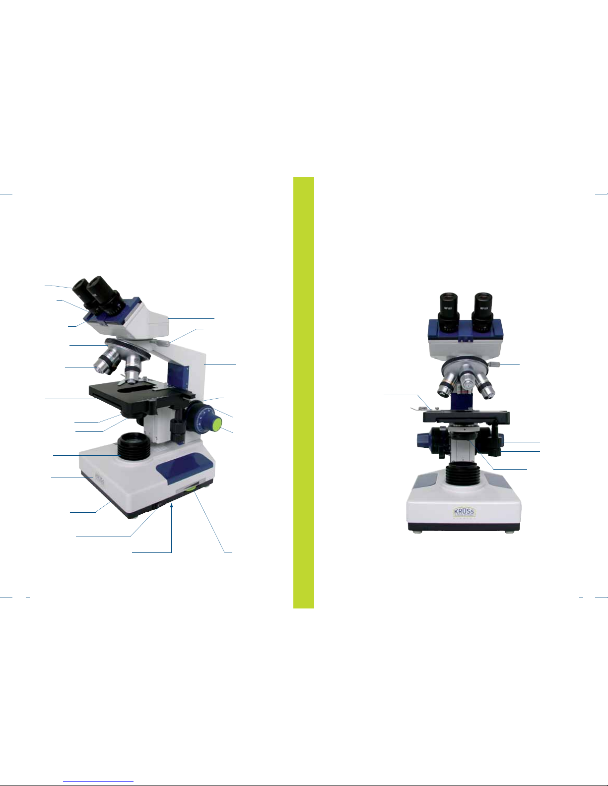
1. Description
1. Description MBL2000
1. Description
Eyepiece
Ocular head
XY stage with retaining clips
Coarse adjustment knob
Fine adjustment knob
On/Off power switch
Condenser with aperature diaphragm
Object lenses (4 pieces)
Lens turret
Brightness control
Stand
Base of stand containing
electronic components
Casing
Mains fuse
(underneath the base plate)
Bulb condenser
Swivel mount for filter
Eye distance adjustment
Eyepiece mount with
diopter adjustment
Locking screw
for ocular head
Set ring for coarse
adjustment - right
Diaphragm adjustment
Adjustment knob X-direction
Adjustment knob Y-direction
Locking screw for ocular head
Retaining clip for cover glass
Page 19

3736
2. Assembly of the microscope
For packaging purposes, the microscope is delivered in several separate parts.
The assembly of the microscope is easy.
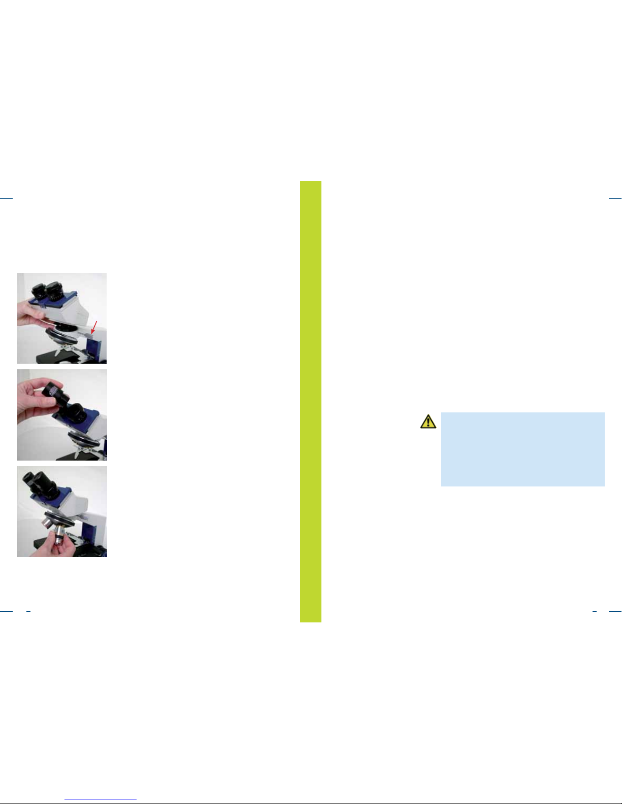
2. Assembly of the microscope
1. Remove the stand from the packaging, attach
the ocular head and fasten it by using the screw
located at the side.
2. Remove the covers and insert the eyepieces into the
ocular head.
3. Unpack the four lenses from the plastic boxes and
screw them into the lens turret.
The microscope is now ready for use. In the appendix
you will find an explanation on how to attach the
accessories.
3. Operating the microscope
3. Operating the microscope
1. Turn on the main switch.
2. Place the sample on the microscope stage.
3. Release the coarse adjustment pre-selection stop
(see 3.2).
4. Focus with the 4x or 10x object lens on the sample.
5. Adjust the eye distance and dioptre compensation
(see 3.1).
6. Swivel in the desired object lens.
7. Lock the adjusting level for the coarse adjustment
pre-selection stop into position (see 3.2).
8. Adjust the light intensity using the brightness
control.
9. Fine adjust the focus using the fine adjustment
knob.
10. Adjust the aperture diaphragm (see 3.3)
Note
In case there is no power available, the mirror
(available as an accessory) can be used to illuminate the sample. For this purpose, remove the bulb
condenser and replace it with the mirror.
The base of the mirror is screwed into the socket of
the bulb condenser.
Page 20

3938
Even after the stage is moved to change the object
lens, it can only be moved to the pre-selected position
with the coarse adjustment knob provided that the fine
adjustment knob has not been re-adjusted.
The sample is therefore back in focus. The adjustment
knob is not affected by the pre-selection stop.
3.1 Eye distance and dioptre adjustment
3. Operating the microscope / 3.1 Eye distance and dioptre adjustment / 3.2 Coarse adjustment
Aperture diaphragm
2/3 of pupil diameter
Pupil
1. Take the eyepiece carriage of the right and left
eyepiece support with both hands and adjust the
proper eye distance
2. The eye distance is correctly adjusted when the
field of vision is in focus with the eyes relaxed.
3. Take note of your eye distance shown on the scale.
4. Now turn the longitudinal tube equalizer ring of the
right eyepiece support to the value indicated on the
eye distance scale.
5. Look through the right eyepiece and focus the
object with the fine adjustment knob.
6. Now look through the left eyepiece and adjust the
tube equalizer ring without touching the coarse or
fine adjustment knob until the sample is in focus.
All transmitted light microscopes have a mechanical
tube length of 160 mm.
3.2 Coarse adjustment The coarse adjustment can be adjusted to run smooth
or rough by turning the knurled set ring between the
microscope stand and the right-hand coarse adjustment
knob. This prevents the sliding of the microscope stage
and any associated focusing errors.
A possible contact between the sample and the object
lens can be prevented by the pre-selection stop which
also makes the coarse focusing easier. After focusing
with the coarse adjustment knob, the lever is turned in a
clockwise direction up to the stop position.
The microscope stage can then no longer be moved
beyond this position with the coarse adjustment knob.
Please note!
When adjusting with the coarse adjustment knob,
you have to ensure that the pre-selection stop is
adjusted to that particular object lens.
Otherwise, it is possible that during the simultaneous
adjustment and viewing through the eyepiece, the
object lens is moved into the sample damaging the
object lens as well as the sample.
3.3 Aperture diaphragm The aperture diaphragm integrated in the condenser
is used to adjust the depth of sharpness of the image
contrast and the resolution power of the microscope
lenses. In order to achieve a perfect image quality, the
diaphragm opening should generally be open 70-80%
of the object lens aperture. You can correctly adjust the
aperture diaphragm by removing the eyepiece. You can
control the image of the aperture diaphragm by the
light path (you might have to dim the light intensity).
Theoretically, the aperture diaphragm must be readjusted after each change of the object lens.
3.4 Oil immersion lenses, marked with “HI” – homogeneous immersion
To make full use of the numeric aperture of an immersion lens, the object lens and sample – in special cases
also the condenser – must be submerged in immersion
oil.
3. Operating the microscope / 3.3 Aperture diaphragm / 3.4 Oil immersion lenses
Important note
Never counter-rotate the right and left adjustment
knobs at the same time.
Page 21

4140
Please proceed as follows:
1. First focus on the sample to be examined with a
low magnifying lens (e.g. 10x).
2. Use the coarse adjustment pre-selection stop as
described in 3.2.
3. Lower the microscope stage by using the coarse
adjustment knob.
4. Apply a drop of immersion oil on the spot where
the sample is to be examined and which is illuminated by the condenser.
5. Swivel the immersion lens into position. Carefully
raise the microscope stage with the coarse adjustment knob as far as it will go (to the pre-selection
stop).
6. If needed, refocus with the fine adjustment knob.
Make sure that there are no air bubbles developing
in the immersion oil.
After use, clean the immersion lens with lens cleaning
paper or a suitable cloth using ether or alcohol).
Important note!
Make sure that during the swivelling of another
object lens, it does not come into contact with the
oil, thus becoming contaminated!
3.5 Cover glass and object holder
The cover glass is placed over the sample. The lenses
provided with an engraving of 0.17 have been corrected for a cover glass density of 0.17 mm, i.e. in case
of dry lenses with a NU (numeric aperture) of 0.7 and
higher, only a cover glass density of 0.17 mm is to be
used as the object lens comes with a cover glass
correction.
A special cover glass for blood counting chambers of
0.4 mm thickness may be used for the achromatic
40x NA 0.65 object lens or for object lenses with lower
magnifications.
Object holder:
We recommend you use object holders with a thickness
between 0.8 and 1.5 mm.
4. Technical data
Optical head Inclined optical head, symmetrical eye distance adjust
ment (55 – 75 mm), dioptre compensation with scale.
Lens turret Quadruple
Achromatic object lenses 4x 0.10 NA 17.04 mm working distance
10x 0.25 NA 8.05 mm working distance
40x 0.65 NA 0.32 mm working distance
100x 1.25 NA 0.13 mm working distance
Eyepieces 10x, focal length 25 mm
Stand Made of metal with coaxial coarse/fine knob with a
range of 30 mm each.
The right coarse adjustment knob comes with a mobility
adjustment, the left coarse adjustment knob comes with
a quick focusing adjustment.
Microscope stage With 0.1 mm increment memory scale, left-right range
of movement 74 mm, forwards - backwards 30 mm.
Low voltage illumination Integrated, 6 V 20 W (or 30 W) halogen bulb with
brightness control.
Condenser Double lens ABBE Condenser, NA 1.25, with centring,
height adjustment and filter holder.
CE conformity The device complies with
EN 50081-1,IEC 1000-4-2,
IEC 1000-4-4 und IEC 1000-4-5.
4. Technical data3. Operating the microscope / 3.5 Cover glass and object holder
Page 22

4342
5. Denitions
Working distance Distance between sample and front lens mount
Numeric aperture A mathematical relationship, directly related to the (NA)
of the aperture ratio and the resolution power of the
object lens.
The NA is the product of the sine of half the aperture
angle of an object lens and of the refractive index of the
medium through which light enters the object lens.
This is an especially important constant for high-perfor mance object lenses.
Resolution power The capacity of the object lens to separate the fine lens
structures of the sample. The resolution power of a
microscope lens is measured by how two adjacent dots
can be separated. (line structures in the object can be
seen as a set of points). The resolution power of micro
scope lens is defined as follows:
The wavelength range of visible light is between 400 µm
and 700 µm.
The resolution power increases when the light wavelength
decreases. The higher the resolution power of the object
lens, the finer the structure of the object can be resolved.
Depth of sharpness Distance between the upper and lower limit of the image
sharpness which is determined by the optical system.
Structures lying outside this limit appear out of focus and
can only be sufficiently seen when using low magnifying
lenses. A low depth of sharpness is a special disadvan tage in microphotography.
Field of view number The number that specifies the diameter of the field in the
eyepiece (diaphragm) in mm.
Diameter of field of view The actual sample field in mm. The diameter of the field
of view of a microscope eyepiece in mm is calculated as
follows:
5. Denitions
A=0.61
wavelength
NA
6. Accessories / 6.1 Object lenses/ 6.2 Eyepieces
6.1 Object lenses As a standard, the microscope is equipped with achro matic lenses 4x, 10x, 40x and 100x (oil).
A 20x achromatic object lens is also available for a
200x total magnification, a 60x achromatic lens for a
600x magnification. In order to achieve improved
magnification of the perimeters of the field of view, the
achromatic lenses can be replaced by flat field achro matic lenses.
The flat field achromatic lenses are also available in
4x, 10x, 20x, 40x and 100x (oil).
Object lens data:
Vergrößerung NA Arbeitsabstand
4x 0.10 17.04 mm
10x 0.25 8.05 mm
20x 0.40 2.10 mm
40x 0.65 0.32 mm teleskopisch
100x 1.25 0.13 mm Öl-Immersion
6.2 Eyepieces
As a standard, the microscope is equipped with one or
two 10x wide-field flat field eyepieces. This results in a
total magnification of 40x, 100x, 400x and 1000x.
When using of one or two 16x eyepieces you can
achieve total magnifications of 64x, 160x, 640x and
1600x.
A 10x pointer eyepiece accessory is available for
measuring and pointing to samples.
A pointer is directed to the centre is in the image
(see fig. 1). By using the scales on the XY stage, it is
possible to measure the distances.
Another accessory for measuring samples is the micro meter eyepiece (see fig. 2)
The micrometer eyepiece has a 15x magnification
which achieves a total magnification of 60x, 150x,
600x and 1500x.
6. Accessories
Abb. 1
Abb. 2
Magnification
of the lens
Field of view number of the eyepiece
Field of view on the object side in mm
=
Page 23

4544
7. Phase contrast device
The phase contrast device can be adapted to the following microscopes:
MML1500, MBL2000 and MBL2000-T
The phase contrast device MML 2032 consists of a
positive phase contrast lens with a phase lag ring (20x),
a centring ring diaphragm and a centring telescope,
dark field and bright field.
The phase contrast device MML 2031 consists of a
positive phase contrast lens with a phase lag ring (40x),
a centring ring diaphragm and a centring telescope,
dark field and bright field.
The phase contrast device MML2030 consists of a
positive phase contrast lens and a centring diaphragm
for 10x, 40x and 100x magnifications and a centring
telescope.
MML 2031
MML 2030
7. Phase contrast device
7. Phase contrast device
Technical data and specifications
When examining colourless, transparent samples in
the bright field, the contrast is often too low. In order
to avoid colouring or to examining living samples,
the phase contrast method can be used.
Coloured samples can be examined because the
different components have different densities. In case
of transparent samples, details in the bright field are
not easy to examine as all components have the same
density.
Functional principle
Depending on the object lens in use, the scale length of
10 units corresponds to:
Object lens 4x = 2500 um
Object lens 10x = 1000 um
Object lens 40x = 250 um
Object lens 100x = 100 um
Only one pointer or micrometer eyepiece should be used
for the binocular microscope as otherwise there maybe a
double image of the scale.
MML 2032
The system works according to the positive phase
contrast method. The individual phase contrast
elements have the following data:
Achromatic phase contrast lens
10x NA 0.25 with ring diaphragm in a centring mount.
Achromatic phase contrast lens
40x NA 0.65 with ring diaphragm in a centring mount.
Achromatic phase contrast lens 100x NA 1.25 for oil
immersion with diaphragm ring in a centring mount.
Centring telescope with an adjustable eyepiece.
PH-1
PH-2
PH-3
Page 24

4746
7. Phase contrast device
The dark field can be used to obtain sharp images due
to border effects such as light scattering and diffraction.
If the sample has a crystalline structure or directional
characteristics, polarized light can also be used.
The phase contrast method is a form of illumination in
which one part of the light beam is superimposed on
the rest of the light beam to produce interferences to
obtain a visible image of an otherwise invisible object.
A clear annular gap in the image plane of the condenser is reproduced on the rear image plane of the object
lens by the condenser and object lens. A phase shift
ring located in the rear image plane of the object lens
causes the light passing through this annular gap to
shift by a quarter of a wavelength compared to the light
diffracted by the object and the part of the rear image
plane not covered by the phase shift ring.
7. Phase contrast device
To convert the microscope to phase contrast operation,
follow the instructions below:
1. Unscrew one of the bright field lenses from the lens
turret.
Installation
2. Place the desired phase contrast lens into the lens
turret.
3. Loosen the fastening screw of the bright field
condenser and remove it from the mount.
Loosing the locking screw and remove the
condenser by pulling it downwards.
Object lens
Condenser
Clear annular gap
Phase annular gap
Sample
Bulb
Light path when using the phase contrast method
The image is generated by the interference effects of the
two combined light beams.
Elements of the otherwise invisible samples appear as
brightness differences due to the effect of the phase annular gap.
Page 25

4948
7. Phase contrast device 7. Phase contrast device
Note!
The use of an additional Abbe transmitted light condenser whereby a centring diaphragm is mounted for
the phase contrast method makes it possible to significantly reduce the time required for converting between
bright field and phase contrast method.
5. Remove an eyepiece from the tube end and replace
it with a centring telescope.
6. Focus the dark pattern of the phase contrast gap of
the object lens by adjusting the eyepiece of the
centring telescope accordingly.
7. Move the microscope stage with the coarse
adjustment knobs to the highest position.
8. Slowly lower the microscope stage until a sharp
image of the bright pattern of the condenser
annular gap appears.
9. The bright pattern must be adjusted until it is con-
centric with and overlapped by the darker pattern.
Adjust both centring knobs which are located on the
front of the ring diaphragm holder of the condenser.
The phase annular gap is intentionally made some what larger than the image of the condenser dia phragm to ensure a complete overlapping and to
prevent light from escaping the phase annular gap.
Such a light scattering would affect the contrast.
Non-adjusted phase
Adjusted phase
4. Insert one of the condensers with the phase
contrast diaphragm into the microscope
(MML2031 or MML2032)
10. Replace the centring telescope with the previously
removed eyepiece.
The microscope can now be used for the examination
of samples with the phase contrast method.
Page 26

5150
8. Dark eld condenser
The dark field condenser can be mounted to the
following microscopes:
MML1500, MBL2000 and MBL2000-T. The dark field
condenser MML2052 is used for general applications
while the dark field condenser MML2053 is especially
designed for liquid and blood tests.
8. Dark eld condenser
Installation When changing the microscope for use in dark field
operation, take the following steps:
1. Loosen the fastening screw of the bright field
condenser and remove it from the mount.
Loosing the locking screw and pull the condenser
downwards.
2. Now replace the dark field condenser upward into
the condenser mount. Adjust the height of the con denser of fasten the locking screw.
The microscope is now ready for use for the dark
field operation.
Installation
The trinocular microscope MBL2000-T is equipped with
a phototube for mounting photo or video cameras.
The use of the photo adapter MML2042 allows the
mounting of a SLR camera to the microscope.
The C-mount video adapter MML2047 allows the
mounting of a video camera to the microscope.
9. Photo and video mounting
9. Photo and video mounting
In order to change the microscope to photo or video
camera operation, take the following steps:
1. Remove the protective cap from the photo tube.
2. Insert the adapter into the photo tube.
3. When using the photo adapter MML2042, mount
the appropriate T2 ring to the adapter.
Connect the photo camera to the T2 ring via a
bayonet coupling. In case of video adapter
MML2047, screw the video camera directly to the
adapter.
4. Pull out the light path divider until there is resis tance. The light runs through the adapter.
5. The microscope with the photo camera or video
camera is now put in operation. In case of a 10x
or 40x magnification, a sample is placed below the
object lens and the image in the eyepieces is
focused using the fine adjustment knob.
Now focus the image on the photo camera or video
camera. After slightly unscrewing the locking screw
of the adapter (S), you can slightly raise or lower the
adapter.
Page 27

5352
In case of the photo adapter MML2042, it may be
necessary to also loosen the stud screw (X) and to
change the distance in the lower adapter area to
achieve a perfect sharpness.
After these adjustments, the microscope with the photo
or video device is ready for use.
S
S
X
10. Maintenance
Adjust the position for a sharp image on the
camera ort he video monitor. This position is fixed
by fastening the locking screw on the adapter.
Recovery and Recycling
The device can be an important source of raw materials. Please do not dispose of as
waste, but collect separateley for the recycling and recovery of the contained materials.
If disposed improperly, the materials may be damaging to the environment and human
health.
The manufacturer of the device, A.KRÜSS Optronic GmbH, collects, uses and recycles
the contained raw materials. However this recovery requires your support.
If you decide to dispose of this microscope, please do not try to open it up or to use
parts of it in any other way than described in this manual, but return the device to the
dealer you purchased it from.
The dealer should take the device back free of cost.
The recovery of the raw materials is effected with respect to the European guideline
2002/96/EC and any other applicable guideline.
Just like all precision instruments, your microscope should be handled with care.
Protect your microscope from dust, condensation, vibration and direct exposure to
sunlight.
Keep the optical system very clean. Remove dust with a soft brush or clean air.
Remove finger prints with a lint-free cloth soaked in an ether/alcohol mixture (80% ether
and 20% alcohol). Special cleaning paper can be purchased in a photo store.
Do not use any corrosive solutions for the microscope!
After usage, place the microscope back into the box and protect it with a protective dust
cover.
10. Maintenance
Important note!
In case of a malfunction, the microscope should be
repaired by A. KRÜSS Optronic or an authorized
repair shop.
Important note!
Aggressive substances may damage the finish of the
plastic casing!
Recovery and Recycling
Page 28

54
Warranty conditions
A.KRÜSS Optronic guarantees the materials and workmanship of KRÜSS microscopes
for a period of 24 months from the date of shipping. A.KRÜSS Optronic will repair
or replace defective devices within this period, given that they fall under terms of the
guarantee. The device must be sent back to A.KRÜSS Optronic for warranty repairs or
service. Shipping from the customer is at the expense of A.KRÜSS Optronic for warranty
repairs, in any other case at the customer’s expense.
A.KRÜSS Optronic guarantees that the hardware specified by A.KRÜSS Optronic for
use with this device will function without error if used according to our manufacturer
guidelines.
A.KRÜSS Optronic does not guarantee error-free and uninterrupted operation of the
device or the accuracy of this instruction manual. A.KRÜSS Optronic is not liable for
consequential damage.
Warranty limitations:
This warranty does not cover errors and damage arising due to improper handling,
through modification, misuse, operation above and beyond the specified environmental
conditions or through unauthorised maintenance.
Further claims will not be accepted or recognised. A.KRÜSS Optronic expressly provides
no guarantee of the workability or economic use in specific application cases.
A.KRÜSS Optronic reserves the right to make changes to this instruction manual and
the technical data of the device in question at any point in time.
This digital refractometer may only be transported when properly packed in the
complete original packaging including the moulded plastic protectors.
Request replacement packaging from your supplier if necessary.
A.KRÜSS Optronic GmbH
Alsterdorfer Straße 276–278
22297 Hamburg | Germany
Tel +49-(0)40-5143 17-0
Fax +49-(0)40-5143 17-60
E-Mail info@kruess.com
Web www.kruess.com
Warranty conditions
Page 29

A.KRÜSS Optronic GmbH
Alsterdorfer Straße 276–278
22297 Hamburg | Germany
Tel +49-(0)40-514317-0
Fax +49-(0)40-51 43 17-60
E-Mail info@kruess.com
Web www.kruess.com
Version 1.0 | Stand: Feb. 2013 | Technische Änderungen und Irrtümer vorbehalten
Version 1.0 | State: Feb. 2013 | Subject to technical modification without notice / errors and omissions excepted
 Loading...