

KRUEGER SVE, LMHS, RVE Installation, Operation And Maintenance Manual

Installation, Operation, and
Maintenance Manual
Single-Duct and Retrofit Terminal Units
Models: LMHS, RVE, SVE
Form #: SIDOM.4 Revised: 03/19
Pre-Installation
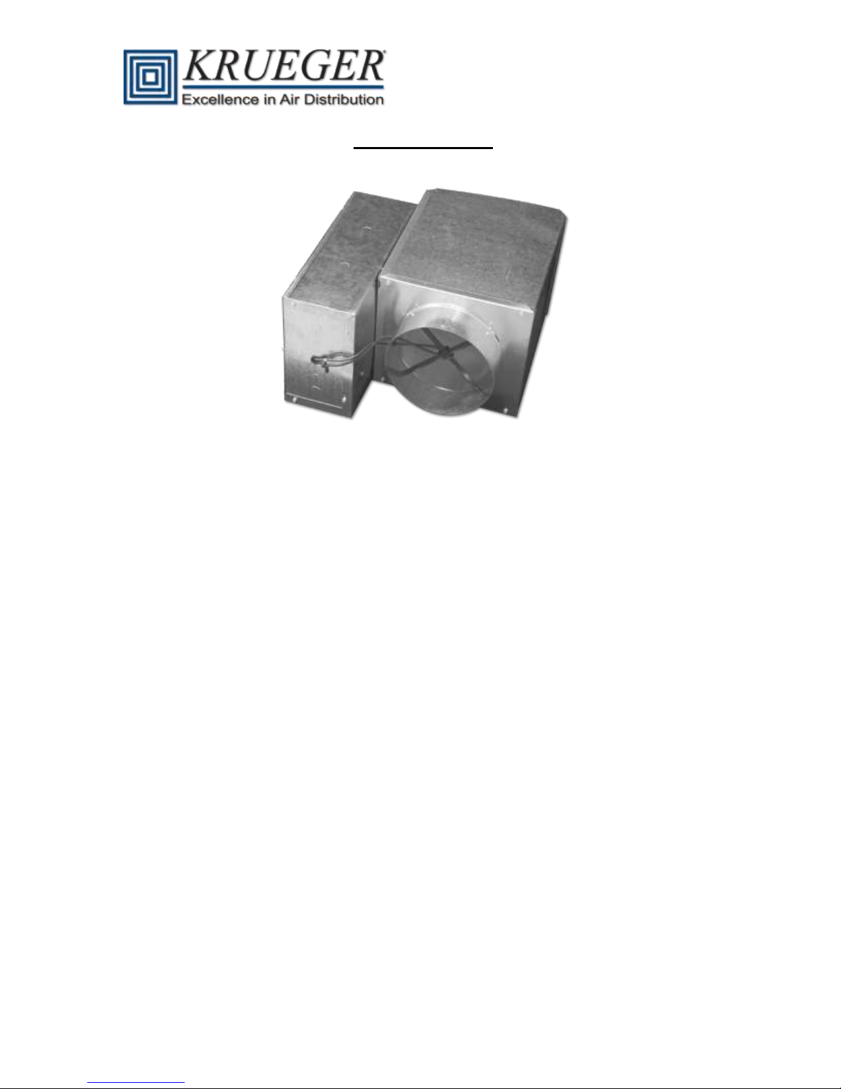
Figure 1 - Basic LMHS Unit
General
The LMHS, RVE, and SVE single duct terminals are available with factory installed Pneumatic,
Analog electronic, and DDC control options. Figure 1 shows a basic LMHS unit.
Shipping
Inspect for damage upon receipt. Shipping damage claims should be filed with shipper at time of
delivery. LMHS units with basic configuration or with hot water coils, RVE units, and SVE units are
packaged into boxes and are stacked onto pallets. LMHS units with attenuation or electric heat are
stacked directly onto pallets. In both instances, pallets should not be stacked on top of one another.
Storage and Handling
Store in a clean, dry, and covered location. Do not stack pallets. When unpacking units, care should
be taken that the inlet collars and externally mounted components do not become damaged. Do not
lift units using collars, inlet flow sensors, or externally mounted components as handles. Do not lay
uncrated units on end or sides. Do not stack uncrated units over 6 ft. high. Do not handle control
boxes by tubing connections or other external attachments.
Unit Weights
Please see Table 5 in Appendix A for unit weights.
Initial Inspection
Once items have been removed from the carton, check carefully for damage to duct connections,
inlet probes or controls. File any damage claims immediately with the transportation agency and
notify the factory.
Form #: SIDOM.4 Page | 2 Revised: 03/19
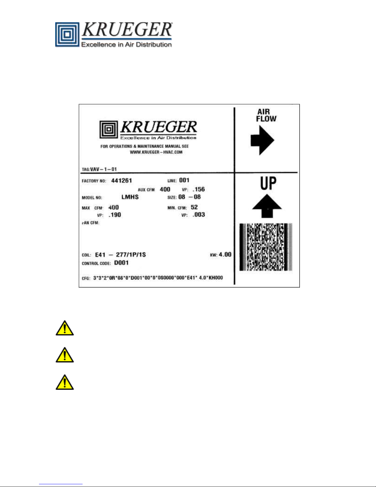
Unit Identification
Each unit is supplied with a shipping label and an identification label. The following Figure 2 is an
example of the identification label that is attached to each unit.
Figure 2 – Example Identification Label
Warning
Disconnect all power to the unit before performing maintenance or service. Unit may
automatically start if power is not disconnected. Electrical shock and personal injury could
result.
If it is necessary to remove and dispose of mercury contactors in electric heat section,
follow all local, state, and federal laws regarding disposal of equipment containing
hazardous materials.
This product can expose you to chemicals including formaldehyde, which is known to the
State of California to cause cancer. For more information go to www.P65Warnings.ca.gov
Installation and Precaution
Check that construction debris does not enter unit or ductwork. Do not operate the central-station
air-handling fan without final or construction filters in place. Accumulated dust and construction
debris distributed through the ductwork can adversely affect unit operation.
Form #: SIDOM.4 Page | 3 Revised: 03/19

Service Access
Provide service clearance for unit access.
Codes
Install units in compliance with all applicable code requirements.
Warranty
All Krueger furnished items carry a 1-year limited warranty from the date of shipment.
Maintenance
No periodic preventative maintenance is required, unless called for by a specific control sequence.
Control Arrangements
The LMHS single duct and RVE / SVE retrofit units are offered with a wide variety of factory-mounted
controls that regulate the volume of air delivery from the unit and respond to cooling and heating
load requirements of the conditioned space. These devices are available in both pneumatic and
electronic arrangements. Some DDC (Direct Digital Controls) control packages provided by others
are also available for consignment mounting.
The following listings contain the basic function arrangements for each control offering. Circuit
diagrams, operating sequences, and function descriptions are contained in separate Application
Data publications because of the variety of functions available. Refer to the specific control
publication for details.
Direct Digital Electronic Control Arrangement (Field Supplied) - Control packages are field supplied
for factory mounting, unless otherwise noted. All DDC control arrangements include an inlet flow
sensor, 24V transformer (optional), and control enclosure. Contact the factory for details about
mounting field-supplied controls.
Analog Electronic Control Arrangement - Pressure independent control packages are available
without supplemental heat, with on/off hot water or electric heat, proportional hot water heat, or with
cooling/heating automatic changeover control. All analog control arrangements include an inlet flow
sensor, 24V transformer (optional), control enclosure, and wall thermostat with LCD display.
2100: Heating control
2101: Cooling control
2102: Cooling with on/off electric heat control
2103: Cooling with on/off hot water heat control
2104: Cooling/heating automatic changeover control
2105: Cooling with proportional hot water heat control
2110: Cooling with Solid State LineaHeat Proportional heat control
2111: Cooling/Heating with automatic change over with up to 3 stages of electric heat control
2113: Cooling/Heating with automatic change over with Solid State LineaHeat Proportional heat
2115: Upstream static pressure monitoring
2116: Downstream static pressure monitoring
Form #: SIDOM.4 Page | 4 Revised: 03/19
Pneumatic Control Arrangement - All control packages are pressure independent (unless otherwise
noted below) and available with or without hot water heat, dual maximum airflow, heating and cooling
maximum airflow and dual minimum airflow. All control arrangements include a standard K4
LineaCross inlet flow sensor.
1100 (Actuator only): DA-NC Pressure dependent control
1101 (Actuator only): RA-NO Pressure dependent control
1102 (Single function controller): DA-NO with or without hot water or electric heat
1103 (Single function controller): RA-NC with or without hot water or electric heat
1104 (Multi-function controller): DA-NO with or without hot water or electric heat
1105 (Multi-function controller): DA-NC with or without hot water or electric heat
1106 (Multi-function controller): RA-NO with or without hot water or electric heat
1107 (Multi-function controller): RA-NC with or without hot water or electric heat
1108 (Dual Maximum Control): DA-NO with or without hot water or electric heat
1109 (Heating/Cooling Maximum Control): DA-NO with or without hot water or electric heat
1110 (Dual Minimum Control): DA-NO with or without hot water or electric heat
1111 (Dual Minimum Control): RA-NO with or without hot water or electric heat
1112 (Heating/Cooling Maximum Control): RA-DO with or without hot water or electric heat
Pneumatic Control Legend
DA: Direct acting thermostat
RA: Reverse acting thermostat
NO: Normally open damper position
NC: Normally closed damper position
Single function controller: Provides single function, i.e., DA-NO
Multi-function Controller: Capable of providing DA-NO, DA-NC, RA-NC or RA-NO functions
No Control Arrangement
0000: Unit with no control box.
D000: Unit with control enclosure and transformer.
D001: Unit with control enclosure and no transformer. Also used for control enclosure and
electric heat.
DXX0: FMA mount for DDC controls with no heat.
DXX1: FMA mount for DDC controls with electric heat.
Form #: SIDOM.4 Page | 5 Revised: 03/19
Installation
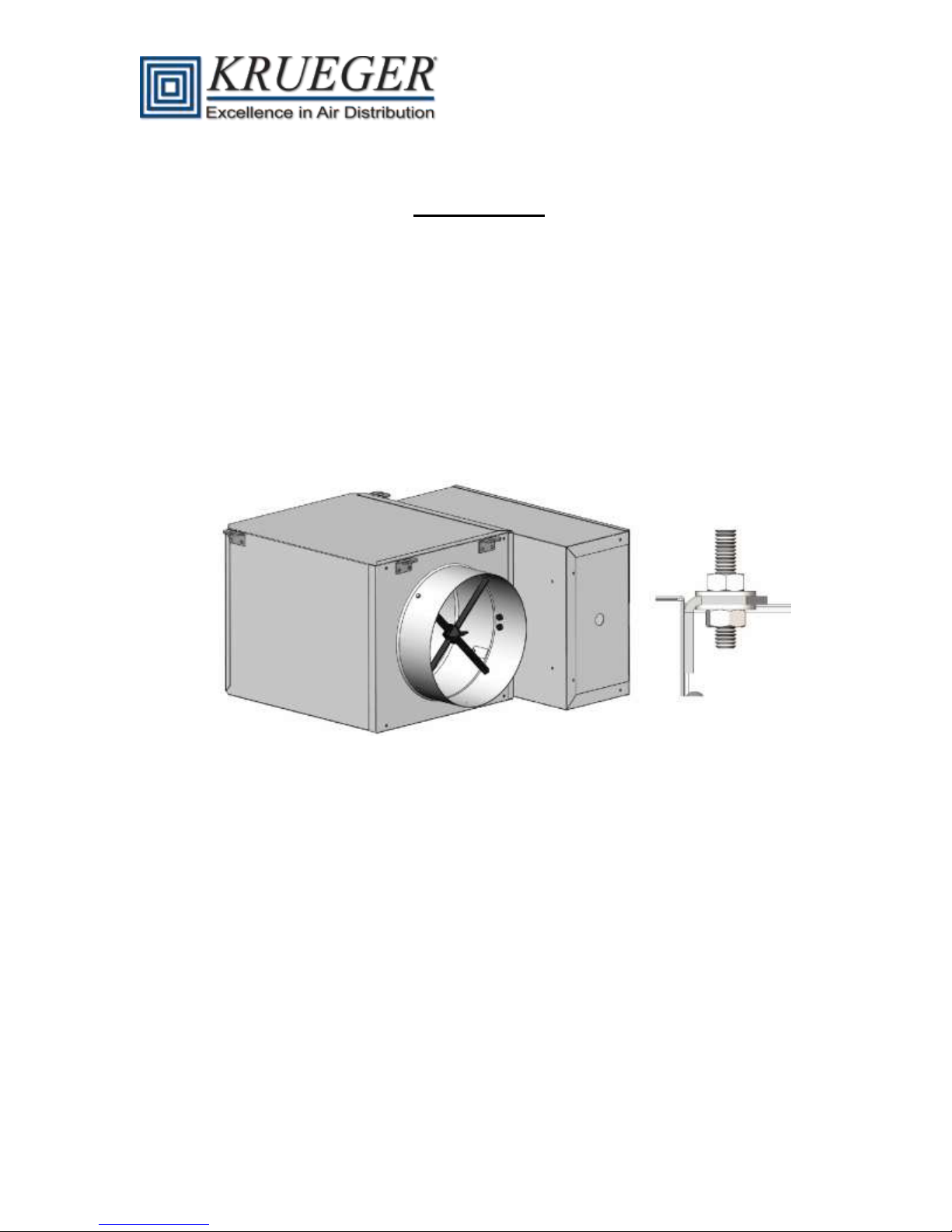
Step 1 - Install Unit
Move unit to installation area. Remove unit from shipping package. Do not handle by
controls, flow sensors or damper extension rod.
Optionally, the unit may have factory-installed hanger brackets.
Suspend units from building structure with appropriate field supplied straps, rods, or hanger
wires. Secure the unit and level it in each direction.
Figure 3 below illustrates the use of optional factory installed hanger brackets for
suspending units.
Figure 3 – Factory Installed Hanger Brackets (field supplied rod, nuts and washers)
Step 2 – Make Duct Connections
Install supply ductwork on each of the unit inlet collars. It is recommended that a length of
straight duct equal to 3 times the diameter of the duct is supplied to the inlet of the unit. An
elbow put at the inlet of the unit will create turbulence at the inlet making it difficult for the
flow sensor to accurately measure the airflow. Check that air-supply duct connections are
airtight and follow all accepted medium-pressure duct installation procedures. Refer to
Tables 6.A, 6.B, and 6.C in Appendix A for pressure and flow data.
Install the discharge ducts. Fully open all balancing dampers.
Form #: SIDOM.4 Page | 6 Revised: 03/19

Step 3 – Install Sensors and Make Field Wiring Connections (Electric
Analog or Direct Digital Controls)
Refer to specific unit dimensional submittals and control application diagrams for control
specifications. All field wiring must comply with National Electrical Code (NEC) and local
requirements. Refer to the wiring diagram on the unit for specific wiring connections. A field-
supplied transformer is required if the unit was not equipped with a factory installed
transformer. See the following Figure 4 for illustration.
Figure 4 - Wiring of Optional Factory Mounted Transformer
NOTE: Refer to the wiring diagram attached to each unit for unit specific information.
Form #: SIDOM.4 Page | 7 Revised: 03/19
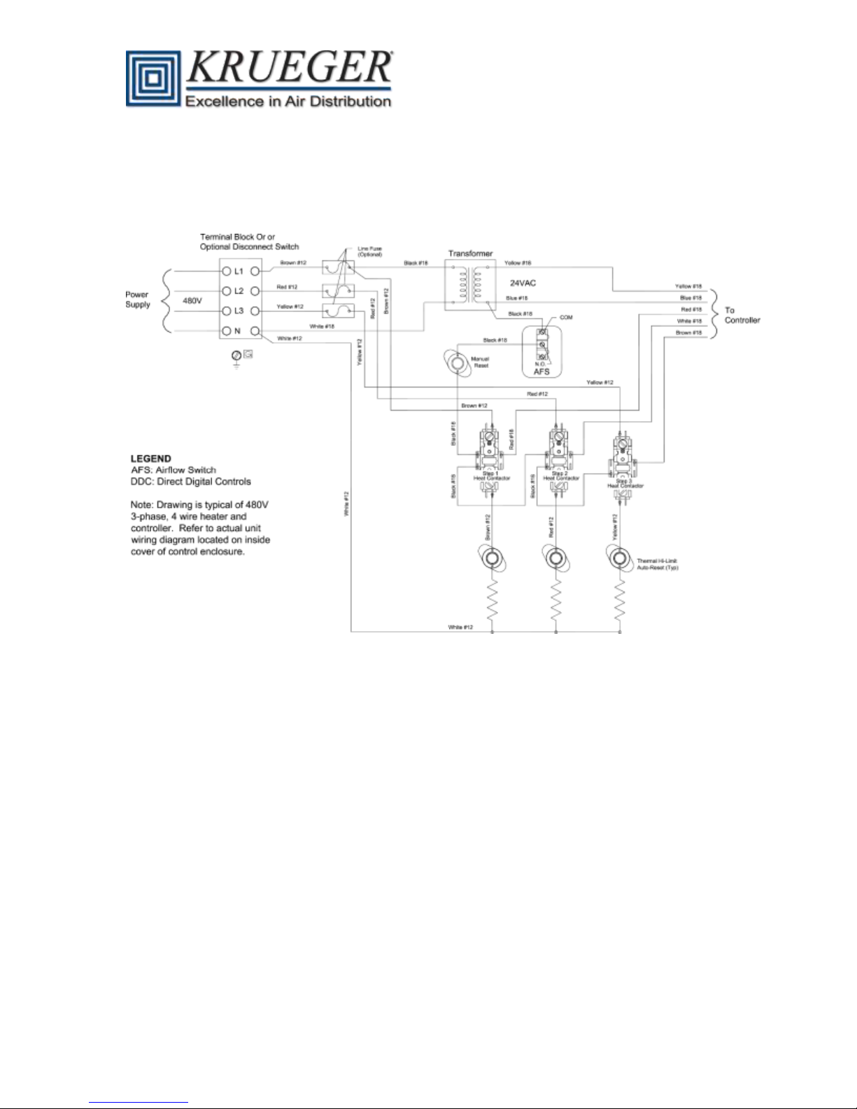
Single duct terminal units with electric heat are supplied with a single point wiring connection in the
heater control box. All unit power is supplied through this connection. Models with electric heat are
factory equipped with a control transformer. The following Figure 5 illustrates an example of a high
voltage wiring diagram that includes electric heat.
Figure 5 - Typical Power Connections for LMHS units with 3-Stage Electric Heat
For wiring and unit ampacities, please refer to Table 7 in Appendix A.
NOTE: Refer to the wiring diagram attached to each unit for unit specific information. Unit airflow
should not be set outside of the range noted in Figure 6 (pg. 11). The minimum
recommended airflow for units with electric heat is at least 75 cfm per kW and should not
drop below the minimum values listed in Table 6.A in Appendix A. The maximum unit
discharge temperature should not exceed 120 F. To prevent air stratification, the ASHREA
Handbook of Fundamentals recommends a discharge temperature not to exceed 90 °F.
Form #: SIDOM.4 Page | 8 Revised: 03/19

Controls Setup
General
The LMHS single duct VAV terminal is designed to supply a varying quantity of cold primary air to a
space in response to thermostat demand. Some units have reheat options to meet heating demand
requirements as well. Most VAV terminals are equipped with pressure compensating controls to
regulate the response to the thermostat independent of the pressure in the supply ductwork. To
balance the unit it is necessary to set both the maximum and minimum set points of the controller.
Each control option has specific procedures for balancing the unit.
Set Points
Maximum and minimum airflow set points are job and unit specific. Where maximum and minimum
airflow levels are not specified on the order, default values are noted on unit label.
Field Adjustment of Minimum and Maximum Airflow Set Points
Each unit is equipped with an amplifying inlet airflow sensor that measures a differential pressure
proportional to the airflow. The relationship between the inlet airflow pressures and CFM is shown
in Figure 6 – Krueger Inlet Airflow Sensor Chart (pg. 11). This chart is also attached to each unit.
The controls on most new projects are Direct Digital Controls (DDC). These controls require that
flow parameters be loaded during start-up to translate the sensed pressure into a measured flow
rate. There are several conventions in use for representing this flow factor; however, there is no
universally accepted method.
1.) Magnification Factor - The magnification factor may be expressed as the ratio of either
velocity or pressure of the output of the sensor to that of a pitot tube.
For example, a velocity magnification may be used. All Krueger probes develop an
average signal of 1” WG @2625 fpm. This gives a velocity magnification of
4005/2625, or 1.52.
The magnification factor may be a pressure factor. In this case, the ratio of
pressures at a given air velocity is presented. For a velocity constant of 2626, at
1000 fpm, this is 0.1451 / 0.0623 = 2.33.
2.) K-Factor: The ‘K-factor’ may be represented in two ways –
It may be a velocity K-factor, which is the velocity factor independent of the inlet
area (2625 fpm/in. WG for all Krueger inlet airflow sensors, Linear and LineaCross).
Alternatively, it may be the airflow K-Factor, which is the product of the velocity
factor and the inlet area. For an 8 inch Krueger unit this would be 2625 * 0.349, or
916. A separate factor is required for each size. The following Table 1 contains the
K-Factors for all Krueger VAV terminal inlets.
CFM=K√∆P
i. CFM= ft.
ii. ∆P= Pressure Differential ("WG)
iii. K=Sensor Constant
3
⁄
minute
Form #: SIDOM.4 Page | 9 Revised: 03/19

Inlet Airflow Sensor Area and K Factor
LMHS, RVE
04
05
06
07
08
09
10
12
14
16
22
Inlet Diameter, inches
4
5
6
7
8
9
10
12
14
16
22
Velocity Magnification
1.52
1.52
1.52
1.52
1.52
1.52
1.52
1.52
1.52
1.52
1.52
Velocity Factor
2625
2625
2625
2625
2625
2625
2625
2625
2625
2625
2625
CFM K Factor
229
358
515
702
916
1160
1432
2062
2806
3665
7000
Inlet Area, Sq. ft.
0.087
0.136
0.196
0.267
0.349
0.442
0.545
0.785
1.069
1.396
2.667
Recommended Min
CFM @ 0.03” WG
40
62
89
122
159
201
248
357
486
635
1212
Table 1 – Inlet Airflow Sensor K Factor
System Calibration of Airflow Sensor
To achieve accurate pressure independent operation, the inlet airflow sensor must be calibrated to
the controller. This ensures that airflow measurements will be accurate for all terminals at system
start-up. System calibration is accomplished by calculating a flow coefficient that adjusts the
pressure fpm characteristics. The flow coefficient is calculated by dividing a unit’s design air volume
(in CFM at a differential pressure of 1” WG) by the standard Pitot tube coefficient of 4005.This ratio
is the same for all sizes, no matter which probe type is installed. Calculate the design air velocity by
dividing the design air volume by the nominal inlet area (in sq. ft.). This factor is the CFM K factor
listed in the Table 1 above.
Form #: SIDOM.4 Page | 10 Revised: 03/19
 Loading...