


K+R Performance Engineering, Inc.
PRO-CUBE
Ò
INSTALLATION AND OPERATING MANUAL
Congratulations on your purchase of the most advanced combination delay box/timer unit available for
today’s precision drag racing. The PRO-CUBE Ò has been designed to give you unprecedented control of
your reaction time and ET with a host of standard features, plus options for up to three general purpose
timers, all in one super-compact unit that can be mounted almost anywhere. The precision available with
these timers makes them perfect for controlling a variety of equipment including throttle stops, shifters, and
multi-stage nitrous systems. You should read and understand this entire manual, including the warranty
section beginning on page 8, before proceeding with installation.
STANDARD FEATURES
Cross-Over: Allows you to release the transbrake switch on a slower opponent’s top bulb on a full
open tree. The delay time is automatically calculated from dial-in and delay values you enter.
Second Hit: You can enter a separate delay for hitting the tree a second time. It’s the same as
having two delay boxes in one. This feature allows you to take two shots at the tree in long crossover situations. You will launch on the faster of the two reactions.
Bump-Down Ò: This powerful feature allows you to improve late reactions by subtracting delay time
after releasing the transbrake switch. You can program the amount of time to subtract, you can
bump-down any number of times, and you can use it for either one or both hits on the tree. In
addition, this feature can be used on Timer 1 during the run. If you have a throttle stop connected to
Timer 1, the Bump-Down feature will allow you to correct for track conditions such as tire spin by
reducing the stop time.
Flinch Protection Ò: Two different methods are provided for preventing red-light disqualification when you
release the transbrake switch before the tree starts.
Run Info: If you use either the second hit or the Bump-DownÒ feature, information will
automatically be displayed to indicate the difference in your reaction times for double-hits, as well as
the number of times you bumped-down your reactions and the number of times TIMER 1 was
bumped-down. This allows you to determine what your reaction(s) and E.T. would have been had
you not used these powerful features.
Transbrake Output: High current output for use on all types of transmission brake, foot brake, and clutch
release solenoids. Handles up to 25 amp load.
Line Lock Output: This output is activated and released simultaneously with the transbrake output but
includes a blocking diode to prevent back feed into the transbrake circuit. It can be used in front
wheel line lock applications or jumpered to the Pro-Stage ä or one of the timer outputs acting as a
“launch control” when connected to a compatible throttlestop. Handles up to 2 amp load.
Transbrake Lockout: A built-in timer prevents activation of the Transbrake and Line Lock outputs for a
programmed amount of time after the transbrake releases. This timer can be set from 0 to more than
an hour. Transbrake activation is automatically re-enabled when the timer completes.
Rev 08-99

Pro Cube
K+R Performance Engineering, Inc.
Pro-Stage ä: This special output controls a Pro-Stage ä compatible throttle stop during the
staging process. Developed by Frank Hawley, the patented Pro-Stage™ system1 allows you to
stage with your foot to the floor for both Pro tree and Full tree. Provides better driver concentration,
more consistency, and reduced wear and tear on the engine and converter.
Output Protection: All outputs are fully protected against shorts and severe overloads by advanced
electronic circuit breaker technology. Faulty outputs are indicated by flashing light on the front
panel, allowing fast diagnosis and correction of system problems.
OPTIONS
1 Timer: 4 stages (2 on/off cycles), first on/off cycle adjustable from 0.000 - 9.999 seconds, second
on/off cycle adjustable from 0.00 - 39.99 seconds. Bump-Down Ò can be used during the
run to make minor adjustments to your settings.
2 Timers: Timer 1 is same as above. Timer 2 has 2 stages (1 on/off cycle) adjustable from 0.00 - 39.99
seconds.
3 Timers: All 3 timers have 2 stages (1 on/off cycle each). Timer 1 adjustable from 0.000 - 9.999
seconds, timer 2 and 3 adjustable from 0.00 - 39.99 seconds.
SPECIFICATIONS
Overall Dimensions (H x W x D): 4.3" x 4.7" x 2.95"
Weight: 1.3 lbs
Power Supply Voltage: 10 - 18 Vdc
Power Supply Input Current (no outputs activated): 0.08 Amps
Output Current, Transbrake: 25 Amps for 1 minute
Output Current, Line Lock: 2 Amps continuous
Output Current, Timers and Pro-Stage ä: 10 Amps continuous
INSTALLATION
1. Mount the unit in a convenient location where you can easily read the display and reach the front
panel when strapped in the driver’s seat.
2. Refer to the wiring diagram for electrical connections.
3. IN ORDER TO DAMPEN VIBRATION, THE UNIT MUST BE MOUNTED USING THE THREE
RUBBER MOUNTS LOCATED ON THE BACK. SUFFICIENT CLEARANCE SHOULD BE
MAINTAINED ALL AROUND THE UNIT SO THAT IT DOESN’T VIBRATE AGAINST ANY
SURROUNDING METAL. NOTE: RUBBER MOUNTS ARE NOT REMOVEABLE.
4. FOR THRU-DASH INSTALLATIONS ALLOW CLEARANCE BETWEEN DASH AND UNIT AND
USE FIRM RUBBER MOLDING TO FILL THE GAP. THE UNIT MUST FIT SNUG IN OPENING.
5. ALWAYS COMPLETELY DISCONNECT THE UNIT BEFORE ANY WELDING IS DONE ON
THE CHASSIS.
1
Pro-Stage™ is protected by US Patents 5,839,419 and 5,855,196.
! Important
2

Pro Cube
what each output is doing.
wiring or equipment problems.
K+R Performance Engineering, Inc.
HOW TO SELECT AND CHANGE SETTINGS
Two three-position switches are used to select the various screens. These switches may be left in any
position while racing, they simply select what is being displayed. The table below shows the content of each
screen and the factory default settings for a fully equipped unit. Some screens may be blank (dashes)
depending on the number of timers installed in your particular unit. Use the adjusment (ADJ) switches just
below the displays to change settings. There is one switch for each digit in the display. Note: Changes to any
of the settings are automatically and permanently saved four seconds after making the change. The decimal
points in both displays will blink to indicate when the save operation is performed. If power is turned off or
the unit is reset within four seconds after making a change, those changes will not be saved.
Lighted LCD Displays
DIAL-IN TIMER ON OPP DIAL-IN TIMER OFF
Indicator lights show you exactly
A blinking light indicates
a shorted output to help you
quickly identify and correct
Reset Switch
Instantly cancels everything
and returns all outputs
to their original state.
Same as turning power off
and back on.
DLY
YOUR
DIAL-IN
10 0 0
10 0 0
DELAY 1 BUMP-DOWN
PRO-STAGE
TRANSBRAKE
TIMER 1
TIMER 2
TIMER 3
RESET
OPPONENT'S
DIAL-IN
12 0 0
TM
Select Dial-In, Tree type, or Delay;
Timer 1, 2, or 3 (as equipped) for adjustment.
Switch can be in any position while racing.
12 0 0
DELAY 2 TB LOCKOUT
R
ADJ
PRO-CUBE
K+R Performance Engineering
DIAL-IN
TREE
INTERFACE (DOUBLE HIT) MODE
in Fcd UAL
(2 TRIGGER SWITCHES)
407-267-2393
TIMER 1
TIMER 2
TIMER 3DELAY
DLY-CFG-TMR
CFGTMR
R
TIMER 1 ON
10 0 0
Center-Sprung Toggles
A separate switch for each
digit for fast, easy adjustment
of settings. Can be held up
or down for scrolling forward
or backward.
Select Transbrake Delay,
Unit Configuration,
or Timer settings
for display/adjustment.
Switch can be in any position
while racing.
TIMER 1 OFF
2 0 0 0
FULL/PRO TREE SELECT
(TIMER VERSIONS ONLY)
FULL LrEE
DELAY 1DELAY 2
10 0 0
-
10 0 0
TIMER 1
MODE
TIMER 2
MODE
n OFFn OFF
( NORMALLY OFF MODE )
BUMP-DOWN
AMOUNT
TRANSBRAKE
LOCKOUT DELAY
0 0 10 12 0
3
TIMER 1 ON
** TIMER 2 ON
3 0 0
TIMER 2 ON TIMER 2 OFF
** TIMER 3 ON
5 0 0
** APPLIES TO 3 TIMER VERSION ONLY **
TIMER 1 OFF
TIMER 2 OFF **
4 0 0
TIMER 3 OFF **
6 0 0
Pro Cube
DUAL TRIGGER MODE
NORMALLY OFF MODE
STAGE 4
K+R Performance Engineering, Inc.
INITIAL SETUP
Single vs Dual Trigger Interface Mode:
The PRO-CUBE Ò allows you to “hit” the tree twice and launch your vehicle on the quicker of two
reactions. If you want to take advantage of this double-hit capability, you have the option of using two
separate trigger (transbrake) switches or a single switch. If you choose not to use the double-hit capability,
you only need one transbrake trigger switch connected to the TRIGGER 1 terminal.
Select either Single or Dual trigger interface mode using any right-side ADJ switch.
The amount of cross-over time you have between the first and second hit will determine
whether it’s best to use one switch or two. Using Single Trigger mode to hit both top bulbs is
generally not recommended unless you’re at least 1.5 seconds faster than your opponent.
Hitting both top bulbs with two separate switches in Dual Trigger mode doesn’t require as
much cross-over time. In Dual Trigger mode, TRIGGER 1 is always used for the first hit, and TRIGGER 2
for the second hit. In Single Trigger mode, TRIGGER 2 is ignored.
Another important difference between these two modes involves the Flinch Protection Ò feature.
Simply stated, flinch protection can prevent you from red-lighting when you accidentally release the trigger
switch before the tree starts. If this occurs using Dual Trigger mode, just press the same trigger switch again
and the delay that was started unintentionally will be reset. The delay will be restarted when the trigger
switch is released. In Single Trigger mode, however, the delay is not reset by pressing the switch again. In
this mode a known red-light situation can only be prevented by pressing and holding the TRIGGER 1 switch
until the bottom of your tree. Your vehicle will launch instantly when the trigger switch is released.
Timer Output Configuration:
Except for the 3 timer version, Timer 1 is a 4-stage output that can be cycled on and off twice. If you
want to cycle this timer on and off just once, use either pair of settings and set the other pair to 0. In the 3
timer version all three timers have 2-stage outputs that can be cycled on and off once each.
For compatibility with all types of equipment, Timers 1 and 2 can be configured for either
“normally off” or “normally on” mode. Timer 3, however, is fixed in “normally off” mode for
most common equipment and cannot be changed. Configure the timers as required for your
equipment using the front panel switches.
Note that the first on/off cycle of Timer 1 is adjustable in 0.001 (one thousandth) second increments
for very precise control. Timers 2 and 3 and the second on/off cycle of Timer 1 are adjustable in 0.01 (one
hundredth) second increments for extended down-track range (up to 39.99 seconds). Note the decimal point
location while setting timer values.
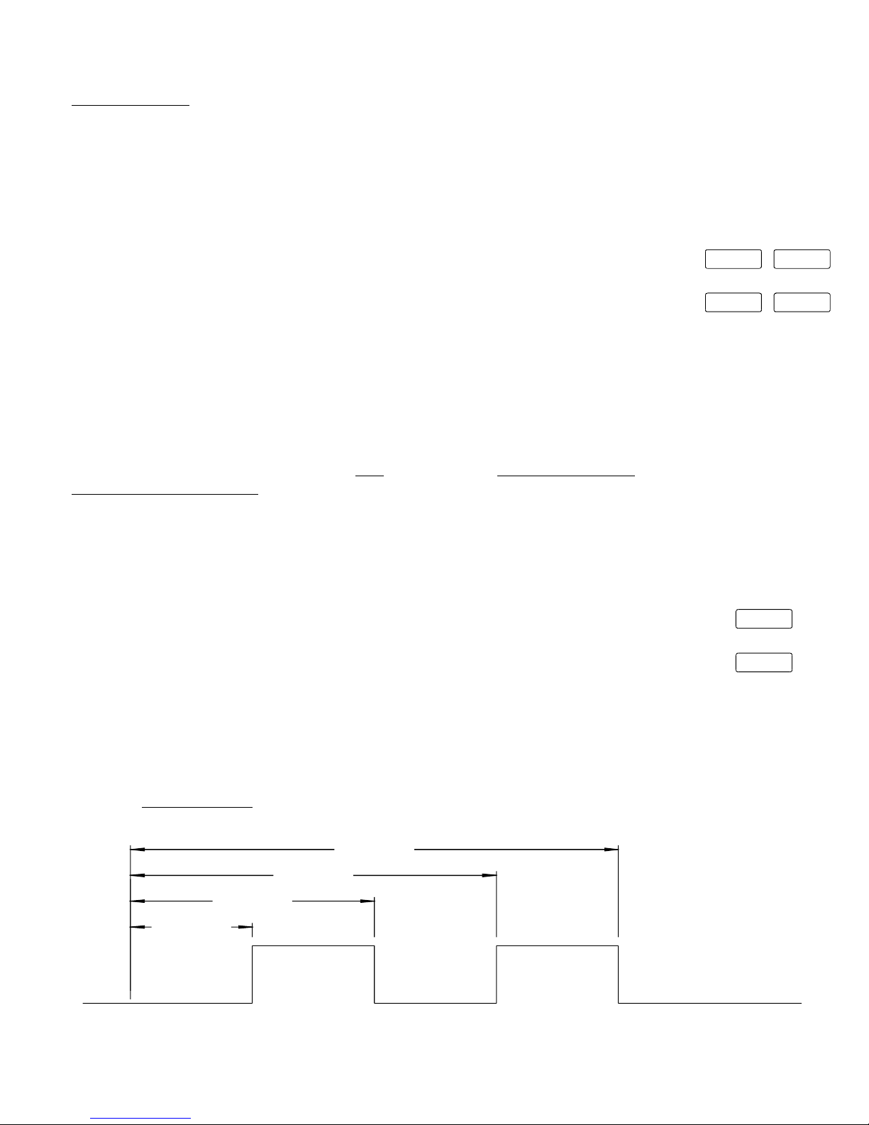
The diagram below illustrates a 4-stage pneumatic throttle stop application using Timer 1 in the
default “normally off” mode and factory settings for each stage. Note that the setting for each stage
represents time into the run, measured from launch.
in Fcd UAL
SINGLE TRIGGER MODE
in Fc
n OFF
NORMALLY ON MODE
n On
5 n 9 L
STAGE 3
STAGE 2
STAGE 1
1.000 SEC
WOT
(POWER REMOVED)
LAUNCH
2.000 SEC
3.00 SEC
THROTTLE
(POWER APPLIED)
CLOSED
4.00 SEC
WOTWOT
(POWER REMOVED)
4
THROTTLE
CLOSED
(POWER APPLIED)
WOT
(POWER REMOVED)
WOT = WIDE OPEN THROTTLE
 Loading...