

Kroy Europe Ltd K6200, K6300 Quick Installation Manual
Quick Installation Guide
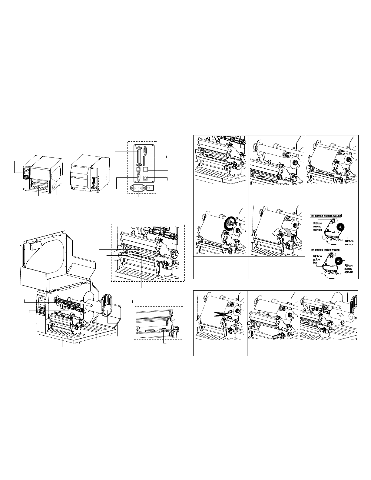
Printer Overview
Note:
The interface picture here is for reference only. Please refer to the product specification for the interfaces
availability.
Loading Ribbon
(1) Lift printer cover open. Push print
head release lever to open print
head mechanism.
(2) Install the ribbon and paper core
onto ribbon supply spindle and
ribbon rewind spindle.
(3) Thread ribbon through the ribbon
sensor slot and print head. Stick
ribbon onto ribbon rewind paper
core, keeping the ribbon flat and
wrinkle-free.
* Loading path for ribbon
(4) Wind the ribbon rewind spindle
clockwise roughly 3~5 circles until
ribbon is smooth, properly stretched
and wrinkle-free.
(5) Close the print head mechanism,
making sure the latches are
engaged properly.
Replace Ribbon
(1) Break the ribbon between the
ribbon guide bar and ribbon rewind
spindle.
(2) Push the print head release lever
to open the print head
mechanism.
(3) Slide the ribbon off from the ribbon
rewind spindle.
Page 1 of 2
Printer Cover
Media
Guide Bar
Label Supply
Spindle
Ribbon Supply
Spindle
Ribbon Rewind
Spindle
Label Roll Guard
Print Head
Platen Roller
Media Sensor
Ribbon Sensor
Print Head
Release Lever
Print Head Pressure
Adjustment Knobs
Damper
Ribbon Guide Bar
Label Guide
Black Mark
Sensor
Graphic LCD with
Backlit Display
Lower Front
Cover
Media View
Window
Fan-fold Paper
Entrance Chute
Power Jack
Socket
RS-232C
Interface
Centronics
Interface
USB
Interface
Power Switch
GPIO Interface (Option)
SD Card Socket
Ethernet Interface
PS/2 Interface
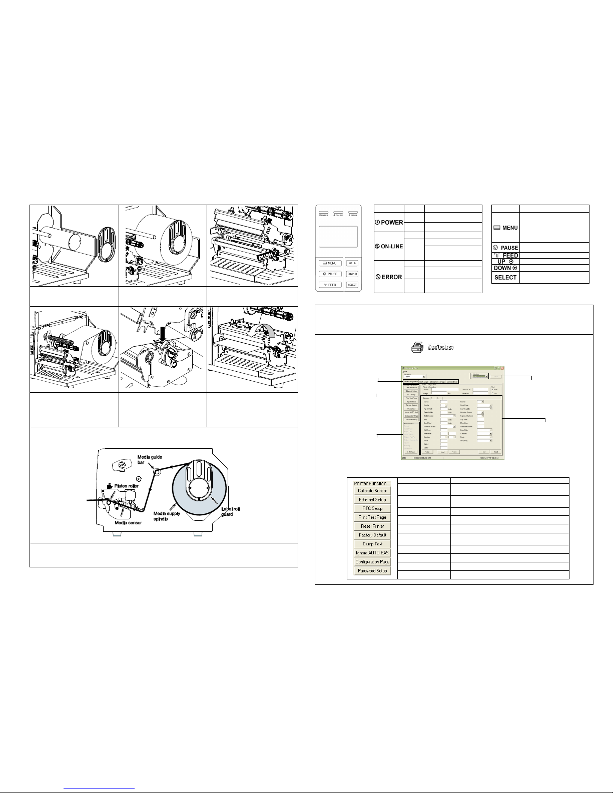
Loading Media
(1) Remove the label roll guard.
(2) Place media roll on label supply
spindle. Replace label roll guard.
(3) Push the print head release lever to
open the print head mechanism.
(4) Pull the leading edge of the label
forward through the media guide
bar past media sensor, and place
the leading edge onto the platen
roller.
(5) Press and hold the label guide to
adjust it to fit the label width.
(6) Close print head mechanism,
making sure the latches are
engaged properly.
* Loading path for media
(7) Using the front display panel, set media sensor type and calibrate the selected sensor. (See “Media Sensor
Calibration” on facing page.)
Note: Re-calibrate the gap/black-mark sensors when changing media.
* For more information and features about this printer, refer to the User’s Manual on the CD disk.
* Specifications, accessories, parts and programs are subject to change without notice.
Control Panel
LED
Status
Indication
Off
Printer power off
On
Printer power on
On
Printer is ready
Blinking
Printer is paused
Printer is downloading
data
Off
Printer is ready
On
Carriage open or cutter
error
Blinking
No paper, paper jam or
no ribbon
Keys
Function
1. Enter the menu system
2. Once in the menu system,
return to previous menu. If
at menu root, exits the
menu system.
Pauses or resumes printing
Advances one label
Scroll up the menu options
Scroll down the menu options
Select the currently
highlighted option
Diagnostic Tool
Diagnostic Utility is an integrated tool incorporating f eatures that enable you to explore a printer ’s settings/status; change
a printer’s settings ; download graphics, fonts and firmware; create a printer bitmap font; and send additional commands
to a printer. With the aid of this powerful tool, you can review printer status and settings in an instant, which makes it
much easier to troubleshoot problems and other issues.
Start the Diagnostic Tool:
(1) Double click the Diagnostic tool icon ( ) to start the software.
(2) Four features (Printer Configuration, File Manager, Bitmap Font Manager, Command Tool) are included in the
Diagnostic utility.
(3) The Printer Functions group provides the following options:
Function
Description
Calibrate Sensor
Calibrate the sensor specified in the Printer
Setup group media sensor field
Ethernet Setup
Setup the IP address, subnet mask, gateway for
the on board Ethernet
RTC Time
Synchronize printer Real Time Clock with PC
Print Test Page
Print a test page
Reset Printer
Reboot printer
Factory Default
Initialize the printer and restore the settings to
factory default.
Dump Text
To activate the printer dump mode.
Ignore AUTO.BAS
Ignore the downloaded AUTO.BAS program
Configuration Page
Print printer configuration
Password Setup
Set the password for DiagTool
Page 2 of 2
Features Tab
Printer Functions
Interface
Printer Status
Printer Setup
P/N: 39-0410001-00LF
 Loading...