

Page 1

TTP-245/343
Thermal Transfer / Direct Thermal
Bar Code Printer
User’s Manual
Page 2

Contents
COPYRIGHT DECLARATION ..............................................................……....... 1
COMPLIANCES .....................................................................................……….. 1
1. Introduction ………………………………………………………………….. 1
2. Getting Started ..............................................................................………. 2
2.1 Unpacking and Inspection.......................................................……… 2
2.2 Equipment Checklist.................................................................…….. 2
2.3 Printer Parts...............................................................................…….. 3
3. Power on Utilities..............................................................................……. 4
3.1 Ribbon Sensor Calibration .......................................................……. 4
3.2 Gap/Black Mark Calibration.....................................................…….. 4
3.3 Self Test ......................................................................................……. 5
3.4 Dump Mode.................................................................. ................…… 6
3.5 Initialisation ...............................................................................…….. 7
4. Setup..................................................................................................……. 8
4.1 Setting Up the printer…………………………………………………..… 8
4.2 Loading the Ribbon...................................................................……… … 9
4.3 Loading Label Stock .................................................................…….. 10
4.4 External Label Roll Mount Installation (Option) ...............…………. 12
4.5 Peel -off Module Installation (Option).....................................………….. 13
4.5.1 Loading the Paper for Peel -off Mode ..........................……….. 16
4.6 Cutter Module Installation (Option) .....................................……….. 18
4.6.1 Loading the Label in Cutter Mode .................................……… 21
5. Maintenance....................................................................................………. 22
5.1 Cleaning .....................................................................................…….. 22
6. Troubleshooting............................................................................……….. 23
6.1 LED Status ................................................................................…….. 23
6.2 Print Quality.............................................................................………. 24
7. Specifications .............................................................................………… 25
7.1 Printer Specifications ...........................................................……….. 25
7.2 Label Stock Specifications....................................................…..…… 26
7.3 Ribbon Specifications...........................................................……….. 26
8. LED and Button Operation.............................................................……… 27
8.1 LED............................................................................................……… 27
8.2 Button Operation.....................................................................………. 28
i
Page 3

Copyright Declaration
The information in this manual is subject to change without notice and does not
represent a commitment on the part of Kroy Europe Limited. No part of this
manual may be reproduced or transmitted in any form or by any means, for any
purpose other than the purchaser’s personal use, without the express written
permission of Kroy Europe Limited.
The TrueType font engine is developed from the “FreeType Project" by David
Turner, Robert Wilhelm, and Werner Lemberg; and all other products referred to
in this document are the trade mark or the registered trade mark of each
of the trademark holders.
Compliances
CE Class B:
EMI: EN 50081-1:1998->EN55022:1998, EN 61000-3-2:2000,
EN61000-4-3:1998
EMS: EN55024:1998
FCC Part 15, Class B
UL, CUL
C-Tick: Class B AS/ NZS 3584: 1997
TÜV-GS: EN60950: 2000
Important Safety Precautions
1. Please read these safety precautions carefully.
2. Keep these instructions for later use
3. Disconnect the printer from the power supply before cleaning. Do not use
liquid or aerosol cleaners. A damp cloth is the most suitable item for cleaning
the printer.
4. Make sure the power supply outlet is near to the printer and easily accessible.
5. The printer is to be protected from humidity.
6. Make sure the printer is installed on a level surface. Tilting or dropping the
printer can cause damage.
7. When connecting to the power supply do not exceed the power requirements.
8. The printer can be operated up to a maximum external temperature of 40 ? .
1
Page 4

2
1. Introduction
Thank you for purchasing the TSC TTP-245/343 series of Thermal Transfer
and Direct Thermal Bar Code Printers. Although the printer takes only a small
amount of space, it delivers reliable, superior performance.
This printer provides both thermal transfer and direct thermal printing at a user
selectable speed of: 2.0, 3.0, 4.0 or 5.0 ips, /2.0 or 3.0 ips. It accepts roll feed,
die-cut, and fan-fold labels for both thermal transfer and direct thermal printing.
All common bar code formats are available. Fonts and bar codes can be
printed in 4 directions, in 8 different alphanumeric bitmap fonts and with a built-in true
type font capability. You will enjoy a high throughput for printing labels with this
printer.
2. Getting Started
2.1 Unpacking and Inspection
This printer has been specially packaged to withstand damage during shipping.
Please carefully inspect the packaging and printer upon receiving the bar code
printer. Please retain the packaging materials in case you need to reship the
printer.
2.2 Equipment Checklist
n Printer unit.
n Software CD.
n Sample ribbon roll.
n Sample label roll.
n Label spindle (1 inch diameter core).
n Label spindle fixing tab.
n 1.5 inch paper core adapter.
n Paper core.
n Ribbon supply/rewind spindle. (2 pcs.)
n Parallel port or USB cable.
n Auto switching power supply.
n Power cord.
n Quick start guide.
Page 5
3
If any parts are missing, please contact the Customer Service Department
of your purchased reseller or distributor.
Options
n External label roll mount.
n Label spindle (3-inch diameter core).
n Keyboard display unit (KU-007 series).
n Automatic cutter module.
n Peel off module.
n External Ethernet print server.
n 802.11b wireless print server.
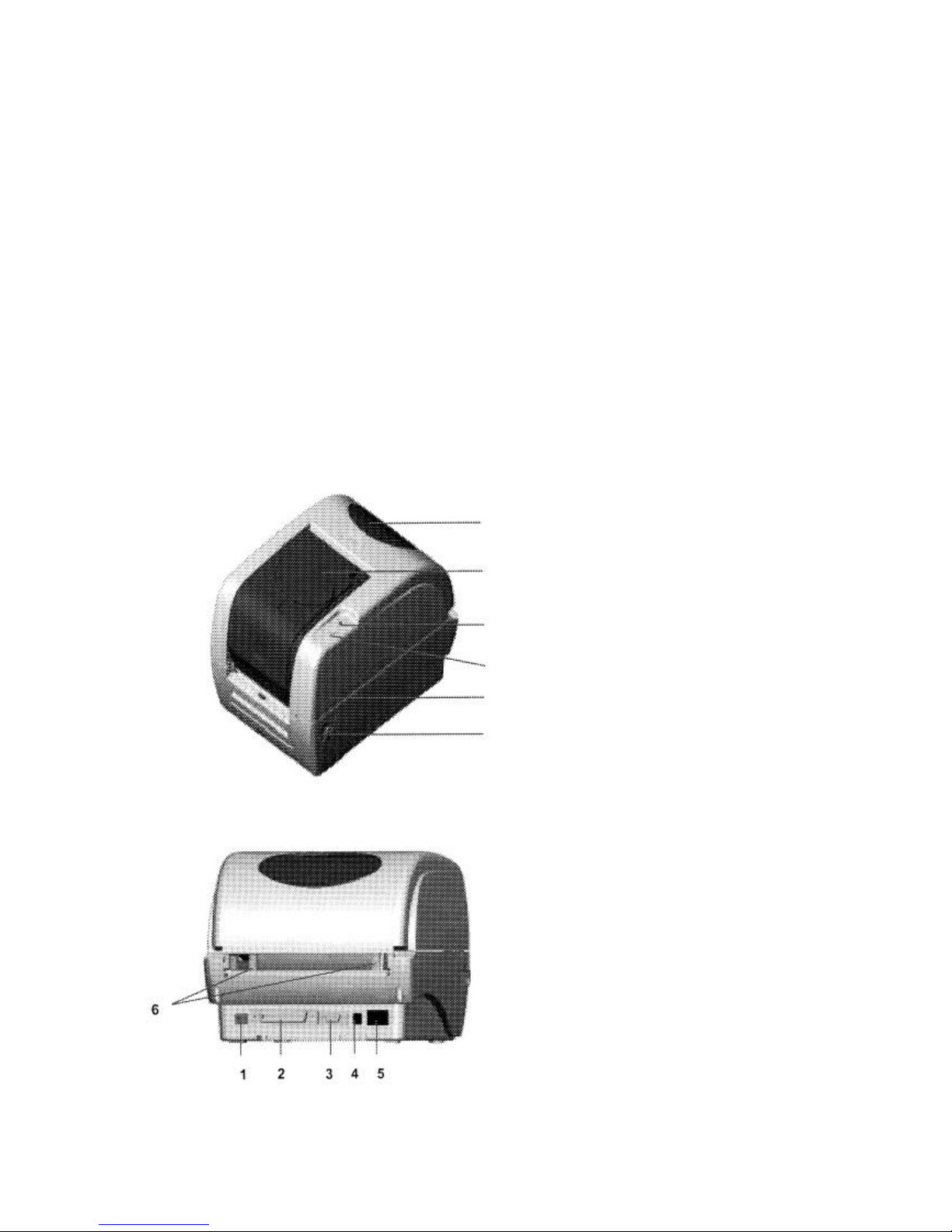
2.3 Printer Parts
Label Roll Capacity View Window
Ribbon Access Cover
LED Indicator
Feed Button
Printer Top Cover
Top Cover Open Lever
Fig. 1 Top front view
1. USB Interface
2. Centronics Interface
3. RS-232 DB-9 Interface
4. Power Jack
5. Power Switch
6. Rear Paper Guide
Fig. 2 Rear view
Page 6

4
3. Power on Utilities
There are four power-on utilities to set up and test the printer hardware. These
utilities are activated by pressing the FEED button and by turning on the printer
power simultaneously. The utilities are listed below:
1. Gap or black mark sensor calibration
2. Label length calibration
3. Print self-test printout
4. Printer initialisation
3.1 Ribbon Sensor Calibration
The printer will calibrate the ribbon sensor sensitivity.
Please follow the steps below to calibrate the ribbon sensor.
1. Turn off the power.
2. Press and hold the feed button then turn on the printer power.
3. Release the button when the LED turns red after the first orange. (Any red will
do during the 5 blinks).
The LED colour will be changed in accordance with the following pattern:
Orange à red (5 blinks) à orange (5 blinks) à green (5 blinks) à green
3.2 Gap/Black Mark Calibration
Gap/black mark sensor sensitivity should be calibrated when:
1. Operating a brand new printer for the first time
2. Changing the label stock.
3. Initialising the printer.
The printer calibrates Gap or Black Mark depending upon your last print job
setting. Please follow the steps below to calibrate the sensor.
1. Turn off the power.
2. Press and hold the feed button then turn on the printer power.
3. Release the button when the LED turns orange. (Any orange will do during the
5 blinks).
The LED colour will be changed in accordance with the following pattern:
Orange à red (5 blinks) à orange (5 blinks) à green (5 blinks)à green
Page 7
5
Whilst calibrating the gap/black mark sensor, the printer will measure the label
length, print the printer configuration and then enter into dump mode.
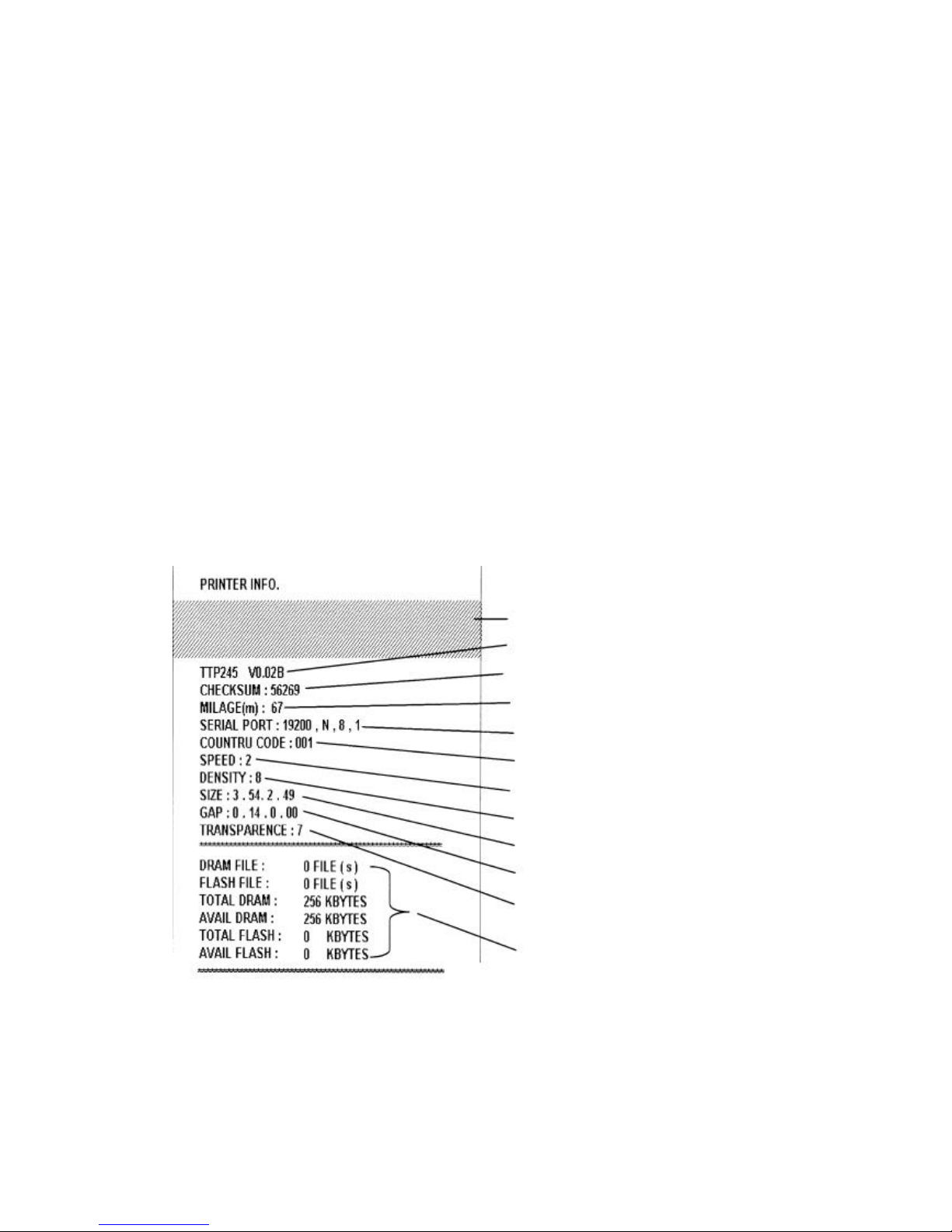
3.3 Self Test
Before connecting the printer to your computer, you can print a test page to
verify that the printer is in proper working order. It prints the print head check
pattern and printer configurations and then enters dump mode.
Please follow the steps below to calibrate the sensor.
1. Turn off the power.
2. Press and hold the feed button then turn on the printer power.
3. Release the button when the LED turns orange. (Any orange will do during the
5 blinks).
The LED colour will be changed in accordance with the following pattern:
Orange à red (5 blinks) à orange (5 blinks) à green (5 blinks) à green
Turn the power off / on to resume normal printing.
Print head check pattern
Firmware version*
Firmware checksum
Printed mileage (me ter)
Serial port configuration
Country code
Print speed (inch/sec)
Print darkness
Label size (inch)
Gap distance (inch)
Gap/black mark se nsor sensitivity
Numbers of download files
Total & available memory space
Fig. 3 Self-test printout
*A character, in the firmware version, is shown as the following:
T: TSPL E: EPL2 D: DPL Z: ZPL U: USB supported
Page 8
6
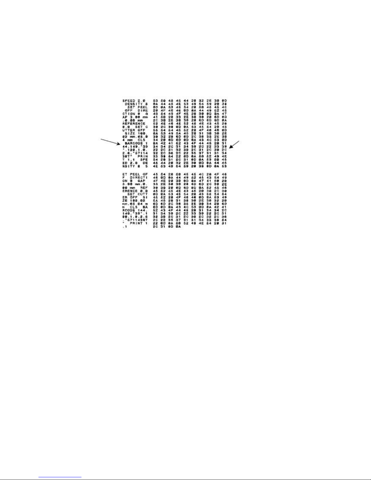
3.4 Dump Mode
The printer will enter dump mode after printing the printer configuration. In the dump
mode, all characters will be printed in 2 columns as follows.
ASCII Data Hex decimal data
related to left
column of ASCII
data
Fig. 4 Dump mode printout
The characters on the left hand side are received from your system and the data on
the right hand side is the corresponding hexadecimal value of the characters. It
allows users or engineers to verify and debug the programme. You just simply turn
the power switch off and on to reset the printer for normal printing.
Page 9

7
3.5 Initialisation
Printer initialisation is used to clear DRAM and restore the prin ter settings to
defaults, which do not include the ribbon setting. It is activated by the following
procedures.
1. Turn off the printer power.
2. Press the button and then turn on the power. The LED will become red, orange
and blink 5 times (for around 5 seconds) then become green and blink 5 times.
3. Release the button when the LED becomes green and starts blinking and then
the printer will be reset (the LED becomes orange then solid green).
The LED colour will be changed in accordance with the following pattern:
Orange à red (5 blinks) à orange (5 blinks) à green (5 blinks) à green
4. The printer configuration will be set as below after the initialisation
Parameter Default setting
Speed TTP-245, 127 mm/sec (5 ips)
TTP-343, 76 mm/sec (3 ips)
Density 7
Label Width 4.25” (108.0 mm)
Label Height 2.5” (63.4 mm)
Sensor Type Gap sensor
Gap Setting 0.12” (3.0 mm)
Print Direction 0
Reference Point 0,0 (upper left corner)
Offset 0
Tear Mode On
Peel Off Mode Off
Cutter Mode Off
Serial Port Settings 9600 bps, none parity,
8 data bits, 1 stop bit
Code Page 850
Country Code 001
Clear Flash Memory No
Page 10
8
4. Setup
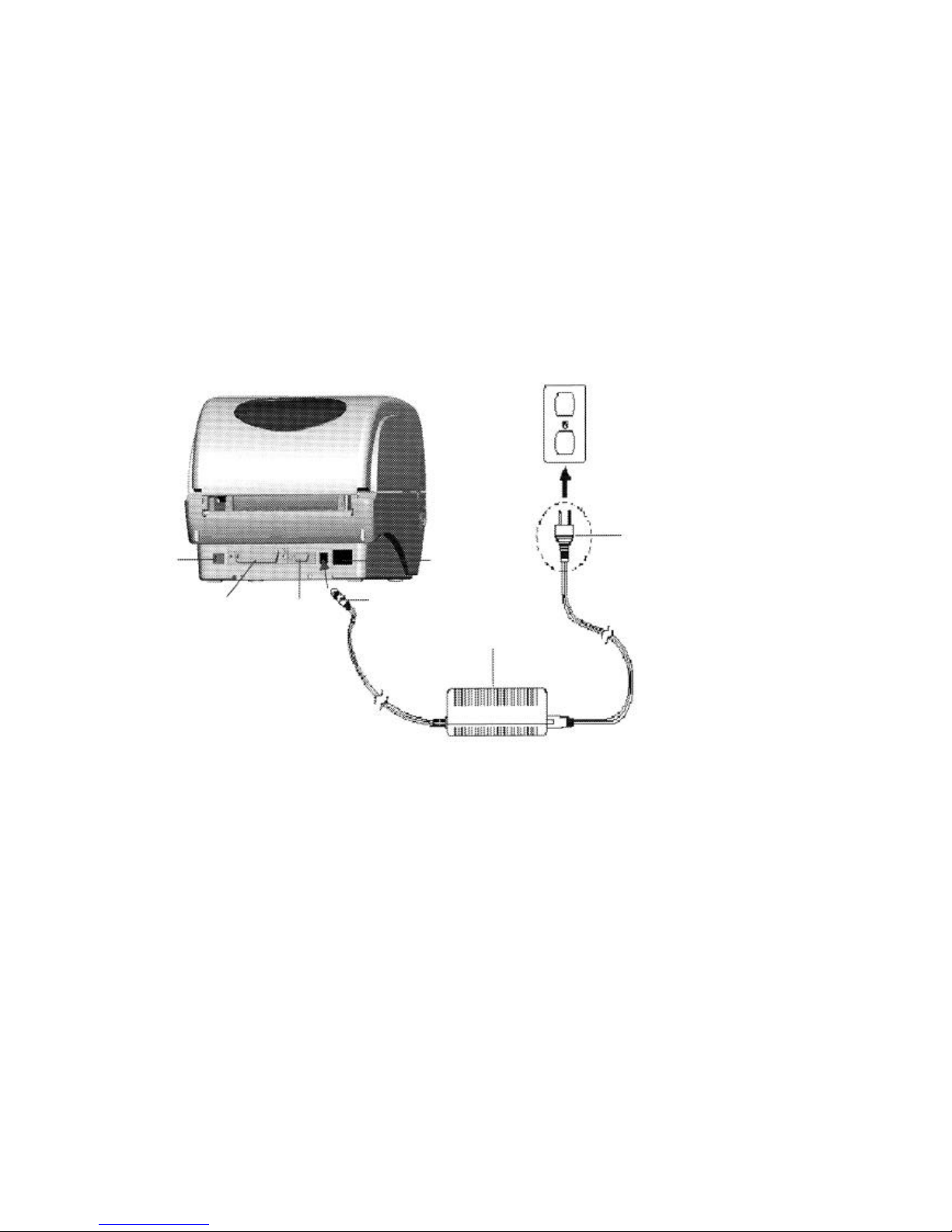
4.1 Setting Up the Printer
1. Place the printer on a flat, secure surface.
2. Make sure the power switch is off.
3. Connect the printer to the computer with the Centronics or USB cable.
4. Plug the power cord into the power supply connector at the rear of the
printer, and then plug the power cord into a properly grounded
power point.
Plug
USB
Power Cable
Centronics RS -232
Power Supply
Fig. 5 Attach power supply to printer
Page 11

9
4.2 Loading the Ribbon
The printer automatically detects if a ribbon is installed after power on and will
switch to thermal transfer or direct thermal printing mode. If the printer does
not detect a ribbon (direct thermal mode), the motor that drives the ribbon
spindles will be turned off. Make sure both the ribbon access cover and the
top cover of the printer are closed when powering on the printer.
1. Push down on the ribbon access cover to unlock and open the cover.
2. Place a paper core on a ribbon rewind spindle.
3. Mount the ribbon rewind paper core on the front hubs.
4. Install a ribbon on the ribbon supply spindle.
5. Mount the ribbon supply spindle on the rear hubs.
6. Attach the ribbon leader to the ribbon rewind paper core.
7. Rotate the ribbon rewind paper core until the ribbon leader is thoroughly,
firmly encompassed by the black section of the ribbon.
8. Close the ribbon access cover.
Paper Core
Ribbon Access Cover
Ribbon Spindle
Back Hub
Front Hub
Fig. 6 Ribbon installation (I)
Page 12

10
Ribbon supply spindle
Ribbon
Leader
Rear Hub
Ribbon Rewind Paper Core
Fig. 7 Ribbon installation (II)
4.3 Loading Label Stock
1. Insert a paper roller into a paper roll ( * If your paper core is 1 inch, remove
the 1.5 inch paper core adapter from the fixing tab).
1.5 inch Paper Paper Roll
Core Adapter*
Fixing Tab
Printing Side
Face Up
Paper Roller
Fig. 8 Label roll installation (I)
2. Open the top cover of the printer by releasing the green cover locking tabs
located on each side of the printer and lifting the top cover. A support bar at the
rear of the printer will hold the top cover of the printer open.
Page 13

11
Lower Case
Fig. 9 Pull the lever to open the cover
3. Place a roll of paper on to the centre of the paper roll mount.
4. Feed the paper, printing side face up, through the Teflon bar and the paper
guide and pass over the platen.
5. Adjust the green centre-biased paper guides in or out so they are slightly
touching the edges of the label backing.
6. To close the top cover of the printer, lift the cover slightly and pull the support
bar forward towards the front of the printer. Close the top co ver of the printer
slowly and make sure the cover locks latch securely.
Note: Failure to securely close and lock the cover will result in a poor
print quality.
Printer Top Cover
Lift the support bar in
the direction of the arrow
Support Bar
Paper Roll Mount
Teflon Bar
Paper Guide
Cover Lock Tab
Fig. 10 Label installation (II)
Page 14

12
4.4 External Label Roll Mount Installation (Option)
1. Attach an external paper roll mount on to the bottom of the printer.
Fig. 11 Attach the external roll mount to the printer
1. Open the top cover of the printer by pushing forward the top cover opening
levers. The top cover support will hold the printer top cover.
2. Place a roll of paper on the external paper roll mount.
3. Feed the paper to the external paper feed opening through the rear paper
guide.
External Paper
Roll Mount
External Paper Feed Opening
Fig. 12 External roll mount label installation (I)
4. Feed the paper, printing side face up, through the paper guide and pass
over the platen.
5. Adjust the paper guide by moving it to the left or right to fit the paper width.
Page 15

13
6. Close the top cover of the printer by lifting up the top cover support and slowly
close the top cover of the printer.
Rear Paper Guide
Top Cover Support
Paper Guide
Platen
Fig. 13 External roll mount label installation (II)
4.5 Peel -off Module Installation (Option)
1. Open the top cover and remove the front panel from the printer.
Front Panel
Fig. 14 Removing the front panel
2. Open the top cover and hold it and push the top cover support down and
backwards and then push the top cover backwards.
3. Use a screwdriver to unscrew the 6 screws on the lower inner cover.
Page 16

14
Top Cover
Top Cover Support
Screws
Flute
Screws
Lower Inner Case Lower Case
Fig. 15 Removing the 6 screws from lower inner cover
4. Use both thumbs to hold the lower case and index fingers to lift up the top
cover opening levers to separate the lower inner case from the lower case.
5. Connect the peeler cable to the 5-pin socket on the printer PCB.
PCB
5-pin Socket
Peeler Cable
Peeler
Tenon
Fig. 16 Connecting the peel -off sensor harness to the main board
Page 17

15
6. Arrange the cable through the bezel.
Bezel
Mortise
Fig. 17 Peeling off the sensor harness installation
7. Flatten a peeler and embed the tenons in the mortises, and you will hear a
clicking sound.
Lower Inner Case
Roller
Lower Case
Tenon Mortise
Fig. 18 Peel -off panel installation (I)
8. Put the lower inner cover back into the lower case.
Page 18

16
Peeler
Roller
Fig. 19 Peel -off panel installation (II)
9. Lift up the peel-off panel to the lower cover to close it.
10. Use a screwdriver to screw back the 6 screws on the lower inner case.
11. Close the top cover by putting the top cover support back into the flute
and push it forwards and then slowly close the top cover.
4.5.1 Loading the Paper for Peel -off Mode
Note: Both thermal paper and plain paper are applicable for the peel-off
function but neither PVC nor vinyl work for the peel-off function.
1. Insert a paper roller into a paper roll.
2. Open the top cover of the printer by pushing forward the top cover opening
levers. The top cover support will hold the top cover of the printer.
Peel-off panel
Backing paper
Opening Top Cover Opening Lever
Fig. 20 Opening the top cover
Page 19

17
3. Place the paper roll on the paper roll mount.
4. Open the peeler by pulling it out.
Peeler
Fig. 21 Opening the peel-off panel
5. Feed the paper, printing side facing up, through the paper guide and pass
over the platen.
6. Feed the paper through the backing paper opening, beneath the roller,
7. Adjust the paper guide by moving it to the left or right to fit the paper width.
Top Cover
Top Cover Support
Roller
Peeler
Fig. 22 Feed the paper through the backing pap er opening, beneath
the roller
Page 20

18
8. Push the peeler back into the printer.
9. Close the top cover by lifting up the top cover support and slowly close the top
cover.
Fig. 23 Complete the label installation for peel -off mode
4.6 Cutter Module Installation (Option)
1. Remove the front panel from the lower cover.
2. Pull the top cover opening levers to open the top cover.
Lower Case
Fig. 24 Pull the lever to open the cover
3. Open the top cover and hold it and push the top cover support down and
backwards and then push the top cover backwards.
Page 21

19
4. Use a screwdriver to unscrew the 6 screws on the lower inner case.
Top Cover
Top Cover Support
Screws
Flute
Front Panel
Screws
Lower Inner Cover Lower Cover
Fig. 25 Removing the 6 screws from the lower inner cover
5. Use both thumbs to hold the lower case and index fingers to lift up the top
cover opening levers to separate the lower inner case from the lower case.
6. Connect the cutter module cable to the 4-pin socket on the printer PCB.
PCB
4-pin Socket
Cutter Cable
Cutter
Fig. 26 Cutter module installation
Page 22

20
7. Put the cable through the bezel.
Lower Inner Cover
Cutter cable Lower Cover Bezel
Fig. 27 Cutter module harness arrangement
8. Put the lower inner case back into the lower case.
9. Place the cutter into the niches of the printer.
Cutter
Niche
Fig. 28 Cutter module installation
10. Use a screwdriver to screw back the 6 screws on the lower inner case.
11. Close the top cover by putting the top cover support back into the flute
and push it forwards and then slowly close the top cover.
Page 23

21
4.6.1 Loading the Label in Cutter Mode
1. Insert a paper roller into a paper roll.
2. Open the top of the printer.
3. Place the paper roll on to the paper roll mount.
4. Feed the paper, printing side face up, through the paper guide and pass
over the platen
5. Feed the paper through the cutter paper opening.
6. Adjust the paper guide by moving it to the left or right to fit the paper width.
Top Cover
Top Cover Support
Paper Guide
Platen
Cutter
Fig. 29 Label installation in cutter mode
7. Close the top cover by lifting up the top cover support and slowly close the top
cover.
Fig. 30 Complete label installation in cutter mode
Page 24

22
5. Maintenance
5.1 Cleaning
Use one or more of the following supplies that meet your needs:
n Cleaning pens
n Cleaning swabs
n Lint-free cloth.
The cleaning process is described as follows
Printer Part Method
Printer Head n Let the print head cool for one minute.
n Use a cleaning pen to swab the print
elements.
Platen Roller n Rotate the platen roller and wipe it
thoroughly with 70% alcohol and a cleaning
swab, or a lint-free cloth.
Exterior n Wipe it with a water-dampened cloth.
Interior n Brush or air blow.
Page 25

23
6. Troubleshooting
This section lists the common problems according to the LED status and
other problems that you may encounter when operating the printer. Also, it provides
solutions.
6.1 LED Status
LED Status / Colour Printer Status Solution Number
Off Off 1
Solid Green On 2
Flash Green Paused 3
Flash Red Stopped 4
1. No power.
n Turn the power switch on.
n Check if the green LED is lit on the power supply. If it is not lit, the power
supply is defective.
n Check both power connections from the power cord to the power supply and
from the power supply to the printer power jack.
2. The printer is on and ready to use.
n No action necessary.
3. The printer is paused.
n Press the feed button to resume printing.
4. The out of labels or ribbons or printer setting is not correct
Out of labels or ribbons
n Load a roll of labels and follow the instructions in Loading the Paper
and then press the feed button to resume printing.
n Load a roll of ribbons and follow the instructions in Loading the
Ribbon and then press the feed button to resume printing.
Printer setting is not correct
n Initialise the printer by following the instructions in “Power on Utility”.
Page 26

24
6.2 Print Quality
Continuous feeding labels
n The printer setting may be wrong. Please do the Initialisation and
Gap/Black Mark Calibration.
No print on the label
n Is the label or ribbon loaded correctly? Follow the instructions in
Loading the Paper or Loading the Ribbon.
n Has the ribbon run out? Follow the instructions in Loading the
Ribbon.
Poor print quality
n The top cover is not closed properly. Close the top cover completely.
n Clean the thermal print head.
n Adjust the print density setting.
n The ribbon and paper media are not compatible.
Page 27

25
7. Specifications
7.1 Printer Specifications
Item TTP-245 TTP-343
Mechanism
Resolution 203 dpi. 300 dpi
Max. Print Width 108 mm. 106 mm
Max. Print Length 1000 mm ( 39” ). 460 mm (16”)
Ribbon Capacity 300 metres with 1” core. (Max. OD 67 mm)
Printing Speed 2, 3, 4 and 5 ips. 2, 3 ips
Peeler function 2, 3 ips 2 ips
Printing Method Direct thermal and thermal transfer printing.
Enclosure
Structure
Dimension
Operation Panel
Double-walled plastic.
Standard Model: 314mm(L) x 213mm(W) x 188mm(H)
One push switch, and one indicator LED (Green,
Orange, Red colours).
Hardware
Sensor
Memory
Interface
Power
Transmissive sensor (offset 6 mm from liner edge).
Reflective sensor (position adjustable).
Head open sensor.
Ribbon end sensor
1M byte Flash memory
2M bytes DRAM
RS-232C (max baud rate, 19,200 bps).
USB: V1.1.
Centronics.
AC input: 100-240V universal auto switching power
supply.
DC output: 24V 3.75A.
Firmware
Font Type
Rotation
Barcode Format
8 alpha-numeric bitmap fonts, and 1 true type font.
0, 90,180 and 270 degrees.
Code 39, Code 93, Code 128UCC, Code128 subsets
A.B.C, Codabar, Interleave 2 of 5, EAN-8, EAN -13,
EAN-128, UPC-A, UPC-E, EAN and UPC2(5) digits
Page 28

26
Command Set
add-on, MSI, PLESSEY, POSTNET, CPOST,
PDF-417, M axicode, and DataMatrix.
TSPL2
Environment
Operation
Temperature: 5 ? ~ 40 ? .
Relative Humidity: 25% ~ 85% (Non Condensing).
Storage
Temperature: -40 ? ~ 60 ? .
Relative Humidity: 10% ~ 90% (Non Condensing).
7.2 Label Stock Specifications
Item Specification
Type Label (Continuous , Die-cut , Fan-fold).
Wound Type Outside wound.
Width 50.8mm ~ 112mm (2.0” ~ 4.4”).
Length 10mm ~ 1000mm (0.4” ~ 39”).
25.4mm ~ 1000mm (1” ~ 39”).(for peeler and cutter)
Thickness 0.06mm ~ 0.19mm.
Roll Diameter 5”.
Roll Core Diameter 25.4mm ~ 76.2mm (1” ~ 3”).
Gap Height 2mm min.
Black Mark Height 2mm min.
Black Mark Width 8mm min.
7.3 Ribbon Specifications
Item Specification
Type Wax, Wax / Resin, Resin.
Core Diameter 1".
Width Max 110mm.
Capacity 300m with 1" core.
Wound Type Outside wound.
Ribbon End Clear or silver end tape.
Page 29

27
8. LED and Button Operation
8.1 LED
LED Colour Description
Green
Orange
Red
This illuminates when the power is on and the device is
ready to use.
This illuminates when the system is detecting the paper
and ribbon status.
This illuminates if there is a printing error, such as paper
empty, ribbon empty, or cover opened etc.
Page 30

28
8.2 Button Operation
Feed
Pause
Ribbon Sensor
Calibration
Gap/Black Mark Sensor
Calibration, Label
Length Measurement,
Self Test and enter
Dump Mode
Printer Initialisation
— Press the button when the LED is green.
n It feeds the label to the beginning of the next
label.
— Press the feed button during printing
n The printing job is suspended.
— Turn off the power switch
— Hold down the button, then turn on the power switch.
— Release the button when the LED becomes red and
starts to blink. (Any red will do during the 5 blinks).
n It will calibrate the ribbon sensor sensitivity.
— Turn off the power switch.
— Hold down the button, then turn on the power switch.
— Release the button when the LED becomes orange
and starts to blink). (Any orange will do during the 5
blinks).
n The LED colour will be changed in accordance
with the following sequence.
Orange àred (5 blinks) àorange (5 blinks) à
green (5 blinks) à green.
n It calibrates the sensor and measures the label
length and prints internal settings then enters
into dump mode.
— Turn off the power switch.
— Hold down the butto n, then turn on the power switch.
— Release the button when the LED turns green after 5
orange blinks. (Any green will do during the 5 blinks)
n The LED colour will be changed in accordance
with the following sequence:
orange à red (5 blinks) à orange (5 blinks) à
green (5 blinks) àgreen.
— Always do the gap/black mark sensor calibration
after the printer initialisation.
Page 31

29
For sales within the United Kingdom, mainland Europe, the Middle East and Africa
please contact:
Kroy Europe Limited
Unit 2, 14 Commercial Way,
Reading, Berkshire RG2 0QJ
England
Tel: +44 (0) 118 9865 200
Fax: +44 (0) 118 9865 205
Website: www.kroyeurope.com
Emails: Product information : info@kroyeurope.com
Technical support : support@kroyeurope.com
For information and sales in North & South America, Australia and the Asia-Pacific
regions please contact:
Kroy LLC,
3830 Kelley Aven ue,
Cleveland
Ohio 44114
USA
Tel: +1 (216) 426-5600
Fax: +1 (216) 426-5601
Website: www.kroy.com
Printed in the United Kingdom
Return to Contents
 Loading...