

Krownlab Baldur Glass Mount Bypassing Doors, Oden Glass Mount Bypassing Doors, Baldur, Oden Installation Instructions Manual
R
INSTALLATION INSTRUCTIONS
PRODUCT: BALDUR + ODEN
CONFIGURATION: BYPASSING DOORS
MOUNT: GLASS MOUNT
Product is covered by U.S. patents. For more information visit www.krownlab.com

1. TOOLS + MATERIALS REQUIRED
TOOLS
• Tape measure
• Imperial allen wrench kit
• Level
• Ratchet with 1/4”, 3/8“ and 1/2” sockets
• Torque wrench capable of measuring 110inlbs(9.5ftlbs)
• #2 Philips screw driver
• Power drill
• One or more of the following drill bits depending on product configuration:
-13/64” metal drill bit for multiple-track systems
-15/64” for soft wood blocking
-1/4” drill for hard wood blocking
TOOLS FOR DRILLING AND CUTTING TRACK
• Miter saw and carbide toothed blade
• 1/2” or 11/16” metal drill bit (11/16” holes provide full 1/4” adjustment in any direction)
MATERIALS
• Blue painters tape
• Pencil or other non permanent marking tool
• Glass panels fabricated for your project
*System additions and optional accessories may require additional tools or materials. See instructions for each accessory for more details.
2. GLASS INSPECTION
INSPECTING GLASS
• Confirm dimensional accuracy
• Ensure holes are seamed and free of chips
• Ensure holes are properly sized
• Reference “Glass panel specifications” for additional information: www.krownlab.com/downloads
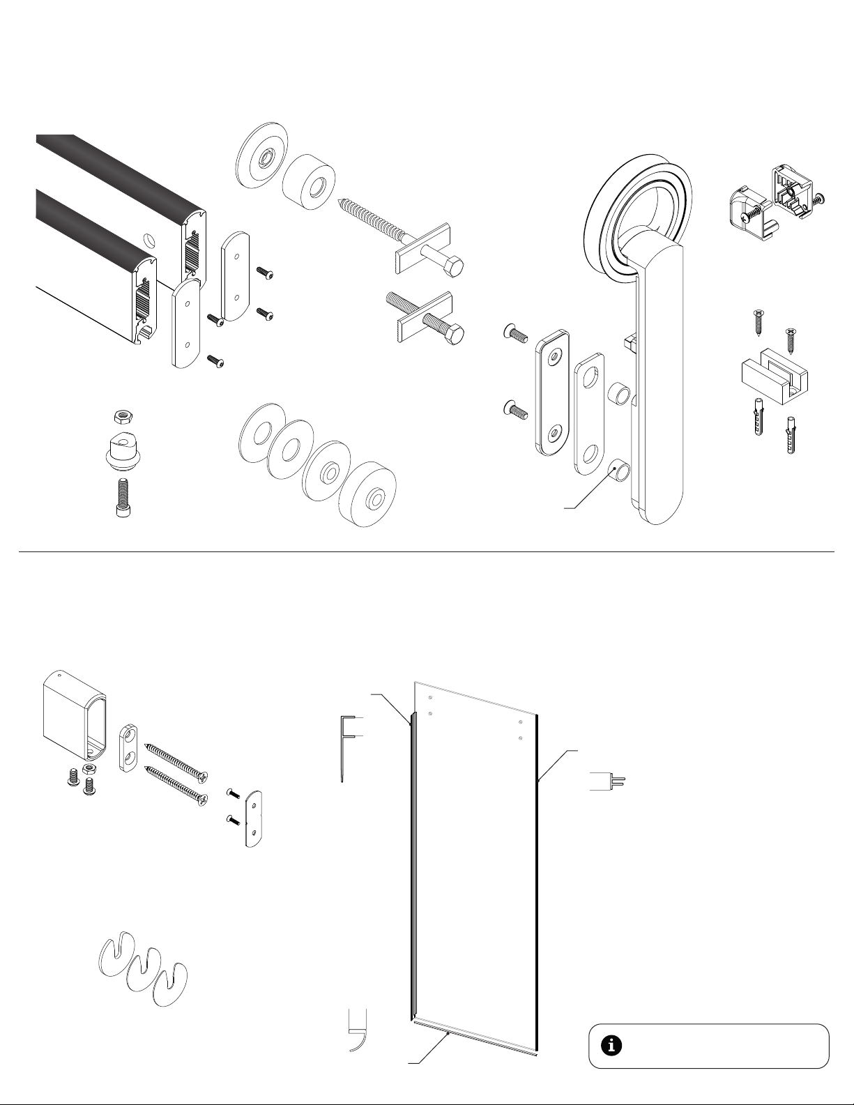
3. VERIFY ALL COMPONENTS
BASE KIT
Rear track assembly
Front track assembly
Door stop kit
Track stand-offs
Drywall insert kit
Track fastener kit
- wood -
Glass bushing
Trolley kit**
Safety stop assembly
Glass door guide kit*
SYSTEM OPTIONS AND ADDITIONS
Perpendicular wall fitting kit
Fin seal
Track shim kit
** Illustration is based on Baldur
Seal kit
*Door guide included may differ.
Edge seal
Door bottom seal
Go to our website for a complete
range of door pulls and locks.
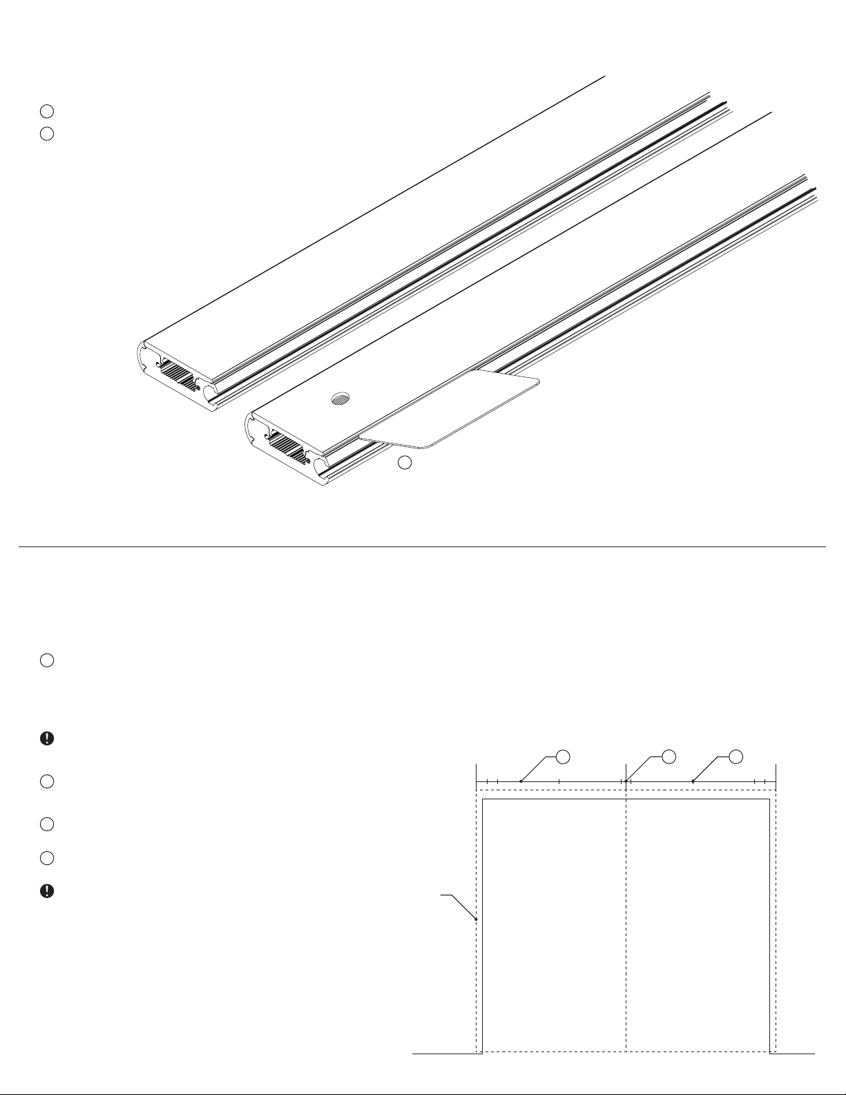
4. REMOVE TRACK COVER
1
Remove the track from the protective sleeve.
2
Gently pry the cover from the base with a slender
plastic (non-marring) tool.
2
5. LOCATE TRACK ATTACHMENT POINTS
1
Determine the height of the track centerline:
HEIGHT = DOOR PANEL HEIGHT + 3”
This will result in a 3/8” clearance between your door
panel and the floor. Adjust if desired or necessary.
Additional clearance can be achieved by the vertical
adjustment feature on the trolleys. See step 20.
2
Mark the track centerline on your wall. (If you run a
length of painter’s tape along your wall, you’ll thank
us later!)
3
On the wall, mark the middle of the opening. This will
be where the track is centered.
4
Determine and mark the locations of all mounting
points along the track centerline.
Krownlab hardware requires a structural wall to
function properly and safely. Each mounting point
must engage an appropriate amount of structural
material: Wood or metal framed walls must have 3” of
solid blocking secured to studs or other framing
members.
Door panel in
desired closed
position
2
3
4
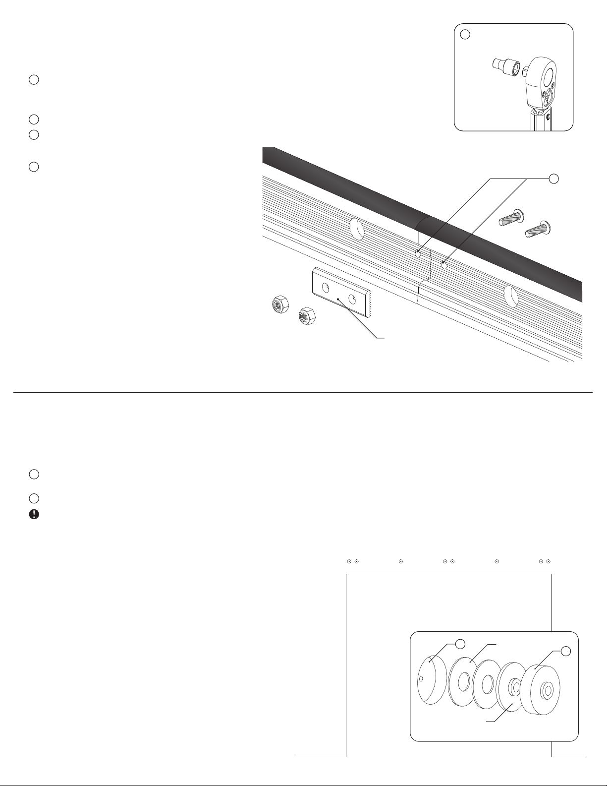
6. LINK MULTIPLE TRACKS
Track Connectors are included with multiple-track systems to keep the tracks in alignment.
Skip to the next step for single-track installations.
1
Butt tracks end to end as they will be installed on your
wall. Using the track connector washer plate centered
over the seam between the tracks as a template,
mark each track for drilling.
2
Drill a 13/64” hole in each track.
3
Connect tracks by assembling the track connector
washer plate as shown. Ensure that washer teeth align
with teeth in the track before tightening fasteners.
Install a 3/8” socket onto a torque wrench and torque
4
the nuts to 48 inch-lbs (4 ft-lbs). You may need to use a
1/8” allen wrench to prevent the screws from rotating
while torquing.
4
2
7.
INSTALL DRYWALL INSERTS
This step is for walls with a non-structural surface only. I.e., drywall, pin-up board or other materials
that are weaker than the wood blocking behind them. Skip to the next step for installations
without these materials.
Use a 1-3/4” spade bit to remove the drywall at each
1
mounting point.
Place a drywall insert into each drywall cavity.
2
To perform their function, drywall inserts must be up
against the structural material of your wall and flush
with the finished surface of the drywall. If needed,
use the included steel shims as shown.
Track connector washer plate
1
Optional insert
for 5/8” drywall
Steel shims
2

8.
PREDRILL STRUCTURAL WALL
1
Drill a pilot hole for each mounting point.
Make sure that each mounting point engages an
appropriate amount of structural material: Wood or
metal stud framed walls must have 3” of solid wood
blocking secured to studs or other framing members.
Predrill 15/64” pilot hole for lag into soft wood
blocking. (1/4” for hardwood)
DETERMINE DESIRED WALL CLEARANCE9.
1
Determine which components are needed to set desired
wall clearance using the formula and table below.
DESIRED CLEARANCE * = PANEL DISTANCE - PANEL THICKNESS
Panel
distance
7/8”
1”
1-5/8”
1-3/4”
Required 1/4”
track stand-off
√ √
√
√
√
Optional 3/4”
track stand-off
√ √
√
Optional
track
stand-off
Optional
panel
spacer
3/16”
Optional
panel spacer
Panel distance
Desired clearance
* If additional wall clearance is required, please contact support@krownlab.com
 Loading...