

Kronoterm WPL-45-K1 HT, WPL-70-K1 HTT, WPL-90-K1 HTT Manual For Installation, Use And Maintenance

Manual for Installation, Use and
Maintenance
Commercial Air-Water Heat Pumps
WPL-45-K1 HT
WPL-70-K1 HTT
WPL-90-K1 HTT
The manual has to be handed over to the end user after installation.
ENG
Id.: 17-16-26-3017-03 | 6.2017

2
Id.: 17-16-26-3017-03 | 6.2017
Manual for Installation, Use and Maintenance - Commercial air-water heat pumps
WPL-45-K1 HT / WPL-70-K1 HTT / WPL-90-K1 NTT
Id.: 17-16-26-3017-03 | 6.2017
Printed in Slovenia, copyright: Kronoterm d.o.o.
This document is copyrighted. Any use outside the provisions of the copyright law without the
permission of Kronoterm d.o.o. is illegal and punishable by law. All previous versions of this document
are void. We reserve the right to make changes and mistakes in print.

Id.: 17-16-26-3017-03 | 6.2017
3
Content
1.
Important information .............................................................................................................. 5
1.1 Symbols ........................................................................................................................... 5
1.2 General ............................................................................................................................ 6
1.3 Safety warnings and instructions .................................................................................... 6
1.4 Obligations of the manufacturer ...................................................................................... 9
1.5 Obligations of the installer during installation .................................................................. 9
1.6 Obligations of the authorised contractor for commissioning at first commission. ........... 9
1.7 Obligations of the user .................................................................................................... 9
1.8 Factory testing ............................................................................................................... 10
2.
Transport and installation of the device .............................................................................. 11
2.1 Transport ....................................................................................................................... 11
2.2 Installation of the device ................................................................................................ 11
2.2.1 Installing the device with a forklift .............................................................................. 11
2.2.2 Installing the device with a mobile crane .................................................................. 12
2.3 Storing and warehousing of the device ......................................................................... 14
3.
Delivery package .................................................................................................................... 14
3.1 The delivery package includes ...................................................................................... 14
3.2 Internal unit .................................................................................................................... 15
3.3 Package and worn-out device management ................................................................. 15
4.
Installation of the device ....................................................................................................... 16
4.1 General .......................................................................................................................... 16
4.2 Location of the device ................................................................................................... 18
4.2.1 Minimal clearance from the device ............................................................................ 20
4.2.2 Levelling of the device ............................................................................................... 20
4.2.3 Removal of side......................................................................................................... 21
4.2.4 Concrete pedestal ..................................................................................................... 21
4.3 Hydraulic connection of the device ............................................................................... 22
4.4 Heating system of machine installations ....................................................................... 22
4.4.1 The scheme of the heating system ........................................................................... 23
4.4.2 Charging of the heating system ................................................................................ 25
4.4.3 Preparing the heating system – secondary ............................................................... 26
4.4.4 Condensate drainage ................................................................................................ 29
4.5 Electrical connection ..................................................................................................... 30
4.6 Removal of the lid of the control unit ............................................................................. 30
4.7 Connecting the external unit ......................................................................................... 31
4.7.1 Power cable connection of the external unit ............................................................. 32
4.7.2 The connection of the communication FTP cable to the external unit ...................... 33
4.8 Connecting the internal device ...................................................................................... 34
4.9 Spatial corrector ............................................................................................................ 34
5.
Commissioning of the device ............................................................................................... 34
6.
MAINTENANCE ....................................................................................................................... 35
6.1 Cleaning the water filter ................................................................................................ 35
6.2 Monitoring the pressure in the heating system ............................................................. 35

4
Id.: 17-16-26-3017-03 | 6.2017
6.3 Cleaning of the heat conductors ................................................................................... 35
6.3.1 Cleaning of the heating system (water side) ............................................................. 35
6.3.2 Cleaning the heat source (air side) ........................................................................... 36
6.4 Disturbances in the operation ....................................................................................... 36
7.
Technical data ........................................................................................................................ 38
7.1 Device dimension drawings .......................................................................................... 38
7.1.1 WPL-45-K1 HT .......................................................................................................... 38
7.1.2 WPL-70-K1 HTT and WPL-90-K1 HTT ..................................................................... 39
7.2 Technical data ............................................................................................................... 40
7.3 Range of operation ........................................................................................................ 42
7.3.1 Heating mode ............................................................................................................ 42
7.3.2 Cooling mode ............................................................................................................ 43
7.3.3 Pressure drop through the device ............................................................................. 43
7.4 Noise ............................................................................................................................. 44
7.5 Legend of data label ...................................................................................................... 46
8.
Notes........................................................................................................................................ 47

Id.: 17-16-26-3017-03 | 6.2017
5
1. Important information
The manual describes the process of installation and maintenance of the device. The installation and
maintenance can only be performed by qualified personnel. Read the manual carefully before the
installation, this way you will be informed about the intended use, functionality and process of handling
the device.
The manual has to be handed over to the end user after installation.
In case the product shall be given to a third person for use, the manual has to be handed over
to them as well.
Definitions
An informed person is a person who reads this manual.
A qualified person has a certificate of expert qualifications.
An authorised commission contractor is trained by the manufacturer and authorised to perform
commission.
The authorised technician is trained and authorised by the manufacturer to perform
maintenance and servicing of the device.
The user uses the device according to its use.
The installer is a person professionally trained for performing hardware and/or electro-
installation work and mounting of the device.
Incorrect use of the device can lead to damage of the device, property or injury to the user. To reduce
risk the manual points out important information with the use of symbols.
1.1 Symbols
These symbols mark various risks for the user or the device.
DANGER:
Risk of situations which can lead to serious physical injuries.
WARNING: Risk of situations which can lead to minor physical injuries.
CAUTION: Risk of situations which can lead to damage or malfunction of
the device.
This symbol marks information for the user.
NOTE:
A notice which holds important information regarding requirements
of the manufacturer.
6
Id.: 17-16-26-3017-03 | 6.2017
1.2 General
NOTE
Read the instructions for use and installation before installation.
NOTE
Any remaking or replacement of original components of the device eliminates
the manufacturer’s guarantee for safe and functional operation. In the case
of undesignated and incorrect use of the device the manufacturer is not
responsible for the consequences and will not acknowledge claims for
damages in these cases. The user is solely responsible for injuries and
damages on the device itself or on other objects resulting from undesignated
and incorrect use of the device.
NOTE
The installation of the device has to be performed in accordance with the
manual; otherwise the manufacturer does not acknowledge the warranty.
NOTE
The device is designed for yearly use of 2000 hours. Choosing an inadequate
power of the device can lead to yearly operation of above 2000 hours which
will reduce the lifespan of the device.
NOTE
Devices with the rated current higher than 16 A are in accordance with IEC
61000-3-12.
NOTE
After connecting the device it is necessary to acquire the guarantee or consult
the operator of the distribution network that the impedance of the network is
lower than prescribed for the individual type of device in the technical data.
This way the device will operate within acceptable limits of disruptions.
Otherwise it is necessary to connect the device to the network using a soft
start device.
DANGER
Failure to comply with the manual and good practise while connecting the
device to the power supply can lead to serious injury or death.
WARNING
Connecting the device to the power source can only be performed by a
qualified installer.
1.3 Safety warnings and instructions
DANGER
It is prohibited to move, shift, clean or service the device while in operation.

Id.: 17-16-26-3017-03 | 6.2017
7
WARNING
It is prohibited to play with the device. Children are not allowed to clean the
device without supervision.
WARNING
The device can be operated independently only by informed persons who are
familiar with the safe operation of the device and understand possible hazards
of its operation. Children older than 8 and people with reduced physical and
mental capacities and with lack of experience and knowledge can only
operate the device under the supervision of an informed person.
WARNING
Before installation and any further adjustments to the device it is necessary to
consider the manual for safe use and maintenance.
WARNING
Installation has to be performed in accordance with national regulations on
electrical installations and with the instructions of the manufacturer. It has to
be performed by a professionally trained person.
CAUTION
The servicing and maintenance of the device can only be performed by a
person authorised by the manufacturer. In case of a malfunction, first contact
the installer who installed the device.
WARNING
It has to be made sure that the device does not endanger anybody. Access
to the device has to be denied to children and persons who are not informed
about the operation of the device.
WARNING
The device must never be cleaned with cleaning agents containing sand,
soda, acid or chlorides because these might damage the surface of the
device.
WARNING
The device contains fluorinated greenhouse gas. This is why tampering with
the device is only allowed to persons authorised for working with the
refrigerant as defined by the national legislation in force. While performing
works on the device, it is necessary to prevent the refrigerant to leak into the
atmosphere.
WARNING
It is necessary to consider all technical data and instructions in this manual as
well as all warnings and notes during planning, design, installation and use of
the device.
WARNING

8
Id.: 17-16-26-3017-03 | 6.2017
Electrical installations have to be inspected in accordance with regulations on
the requirements for low voltage electrical installations in buildings by the
installer of electrical installations.
DANGER
Connecting the devices power cable can be performed by a qualified
electrician. During the procedure the device must not be live.
WARNING
In case the power cable of the device is damaged it has to be immediately
replaced. The replacement can only be performed by the installer or
authorised maintenance worker.
WARNING
Before opening the device disconnect all electrical circuits and make sure the
device is not live.
CAUTION
Putting any kinds of items on or next to the device is prohibited.
CAUTION
In case the device is placed on the ground which is more subject to the
transfer of vibrations than a classical concrete panel with a screed, it is
necessary to underlay the device with a suitably thick and quality anti-vibration
underlay.
CAUTION
The device must not be placed in a room where it cannot be removed. Later
walling or setting up of other obstacles next to the device is forbidden.
CAUTION
In three-phase versions of the device it is necessary to ensure the correct
arrangement of phases when connecting it to the power supply.
CAUTION
For the correct operation of the device, the electrical distributor has to provide
electricity of adequate quality (SIST EN 50160). In normal conditions this is
within ± 10 % of the rated voltage. The data about the state of the electrical
grid have to be acquired from the electrical distributor.
CAUTION
Operation of the device with a frequency converter is forbidden.
CAUTION
Connecting the device to the electrical network has to be performed in
accordance with the standards for connecting devices to the electrical
network. Connect the device to the electrical network via the power supply
cut-off which is installed into the electrical installation under the regulations in
force.
Id.: 17-16-26-3017-03 | 6.2017
9
1.4 Obligations of the manufacturer
The manufacturer guarantees that the device is in accordance with current European directives and
standards. The device is marked with the mark CE and it has all the necessary documentation.
We reserve the right to make changes to the manual without prior notice.
As manufacturer we do not take responsibility for the consequences arising from:
Non-compliance with the manual for the device.
Incorrect and/or inadequate maintenance of the device.
Non-compliance with the manual for the installation of the device.
1.5 Obligations of the installer during installation
The installer is responsible for installing the device in accordance with the following requirements:
To thoroughly study the instructions for use and installation accompanying the device before
installation.
To install the device in accordance with the instructions and national legislation, policies and
standards in force.
1.6 Obligations of the authorised contractor for commissioning at
first commission.
CAUTION
The first commission can only be performed by the contractor of commissions appointed by
the manufacturer in accordance with the instructions for commission.
The contractor for commissions is responsible for commissioning the device in accordance with the
following requirements:
Performs the first commission and with the installer of others section of heating system
eliminates all eventual irregularities found at the commission.
To train the user for operating the device and settings.
Alerts the user to regularly maintain the device for keeping the device functioning properly
throughout its entire lifespan.
Gives the user all the documentation accompanying the device.
1.7 Obligations of the user
For ensuring unobstructed and effective operation of the device the user has to follow the following
instructions:
To thoroughly study the instructions for use and installation accompanying the device before
use.
To have a qualified and authorised installer perform the installation of the device.
To have a contractor for commissions perform the commission.
Allow the authorised contractor for commissioning or ask him to thoroughly explain the
functioning and how to operate the device.
Ensure regular yearly inspections and maintenance of the device by the authorised
maintenance worker.
Store this manual in an appropriate dry place close to the device.

10
Id.: 17-16-26-3017-03 | 6.2017
1.8 Factory testing
For ensuring the high quality standard every device is tested in production for the following:
Tightness of the cooling cycle,
Water-tightness
Electrical safety and
Functionality.

Id.: 17-16-26-3017-03 | 6.2017
11
2. Transport and installation of the device
2.1 Transport
CAUTION
The device must be transported with transport devices.
Secure the device during transport to prevent damage.
Transport the device in vertical position.
It is prohibited to tilt the device above 45°. Otherwise, damage to the cooling system
may occur.
2.2 Installation of the device
NOTE
When installing the device, it is necessary to take into account that the centre of gravity is
not in the middle of the device. To help manipulating the device, there are stickers on the
device indicating the centre of gravity.
CAUTION
Installation can only be performed with a forklift or mobile crane. Other installation methods
are not permitted.
2.2.1 Installing the device with a forklift
When inserting the forks of the forklift under the device, care must be taken not to damage the heating
cable (green colour) intended for preventing freezing in the condensate drainage pipe.
CAUTION
Appropriate transport equipment must be used for installing the device. Safety regulations
and good practise have to be followed.

12
Id.: 17-16-26-3017-03 | 6.2017
2.2.2 Installing the device with a mobile crane
To manipulate the device with a mobile crane, the so-called manipulation equipment provided by the
manufacturer of the device and shipped on customer demand must be used on the site. The customer
must return the equipment after completing the installation of the device.
Manipulation equipment
Preparing the device for transport
Two U-profiles are inserted through the out-most supporting legs. The U-profiles serve as leads for the
connecting straps, they also protect against damage because there are screws on the bottom of the
device which could tear the straps.
The transport frame is fixed to the mobile crane on the ground and is then lifted above the device; it is
then secured to the device with the straps. The transport frame must be positioned approx. 20 cm above
the device. The transport frame must not be placed or laid against the roof of the device because this
could lead to damage of the roof.

Id.: 17-16-26-3017-03 | 6.2017
13
Devices with higher power are manipulated in the same manner as those with lesser power (described
above), but the transport frame used is bigger, and an additional strap and U-profile are used (picture
below).

14
Id.: 17-16-26-3017-03 | 6.2017
2.3 Storing and warehousing of the device
The device has to be stored in a dry and clean place. The allowed storing temperature is between 10
°C and 45 °C, for a short period (up to 24h) also up to 50 °C.
3. Delivery package
3.1 The delivery package includes
Compact heat pump (device) for external installation (external unit).
Controller unit TERMOTRONIC 3000 (internal unit)
Manipulation equipment (see chapter 2.2.2).
Manual for Installation, Use and Maintenance.
Instructions for use.
Filter (optional).
Rubber compensator or flexible pipe (optional).
Circulation pump (optional).
STANDARD
LABEL

Id.: 17-16-26-3017-03 | 6.2017
15
3.2 Internal unit
The internal device is installed depending on the design of the heating system:
Basic wall control unit TT3000 - see Manual for Installation, Use and Maintenance of the
Wall Control Unit TT3000,
Expansion wall control unit TT3000 - see Manual for Installation, Use and Maintenance of
the Expansion Wall Control Unit TT3000,
3.3 Package and worn-out device management
Sort the package according to cardboard, wood and foil and dispose of it in appropriate
containers.
After the lifespan of the device ends it has to be disposed of in accordance with the legislation
on waste electrical and electronic devices in force.
Coolant
The device holds the fluorinated greenhouse gas. You have to prevent leakage of the gas into the
atmosphere. During a maintenance procedure or removal of the device it has to be made sure that the
gas is removed in accordance with the current regulations on the use of substances harmful to the
ozone and fluorinated greenhouse gasses.
16
Id.: 17-16-26-3017-03 | 6.2017
4. Installation of the device
The device is installed on the open, as close to the DHW room of the main building as possible (this
lowers energy losses) and is connected to the heating system.
4.1 General
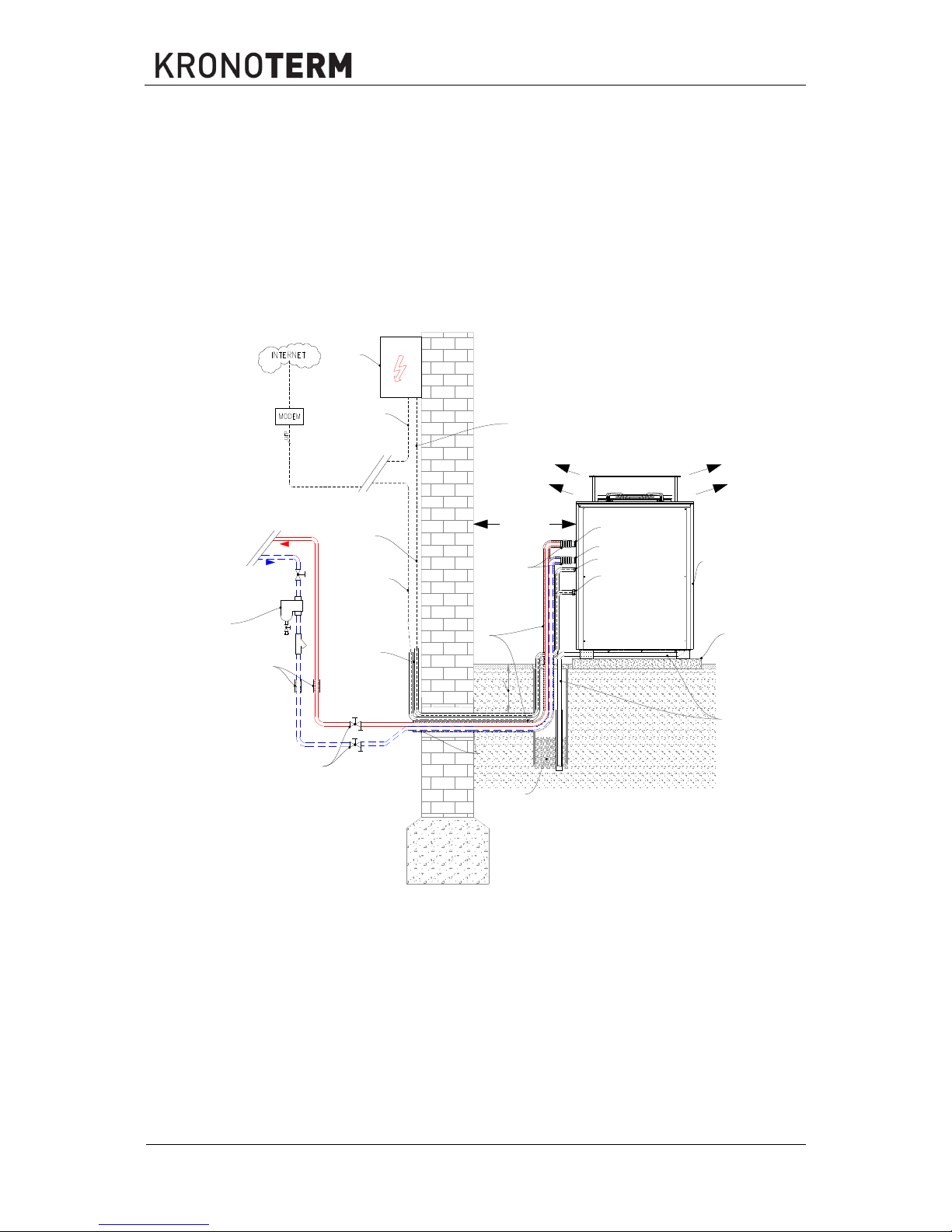
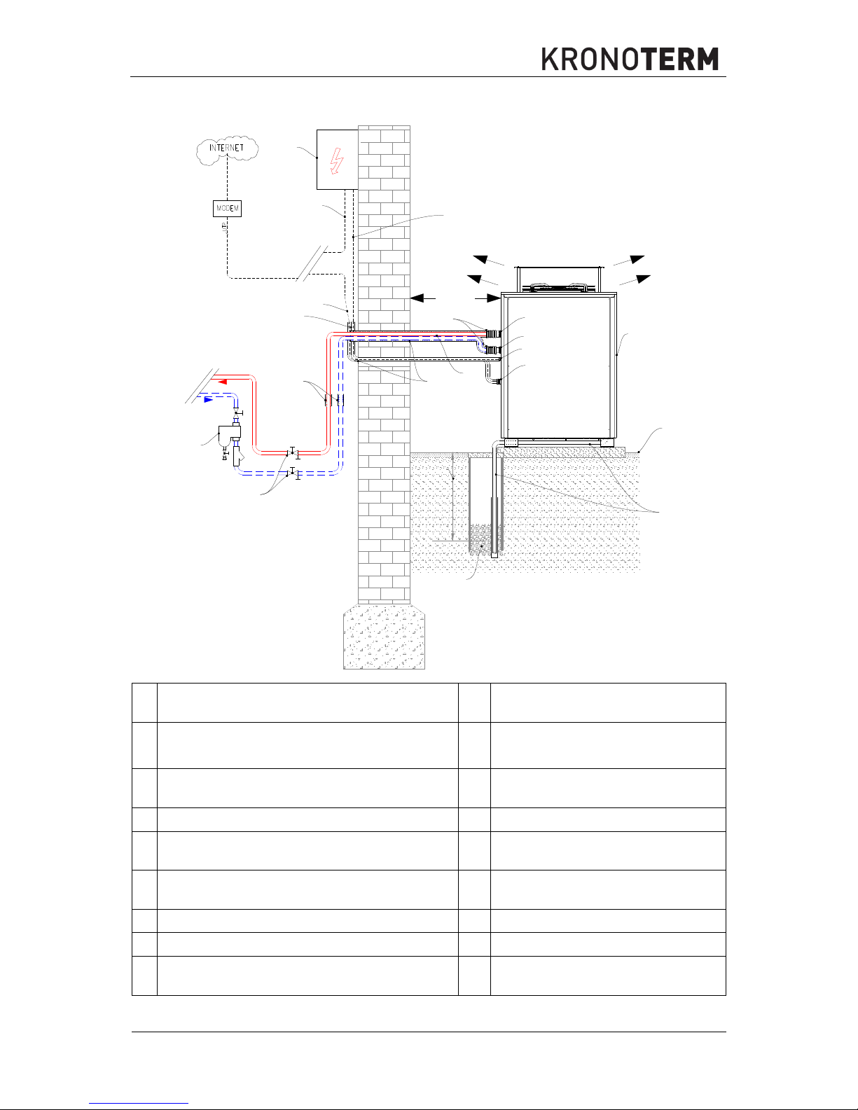
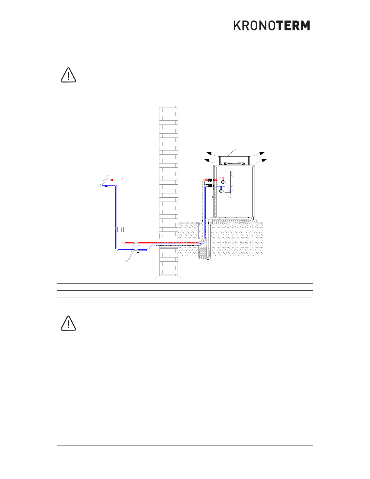
The device enables a machine connection with the DHW room from the bottom (INSTALLATION-V1)
and back (INSTALLATION-V2) side.
INSTALLATION-V1
P10
P4
P9
P12
P11
P3
P5
P7
B
A
P5
P6
P7
P5
P15
A
BAB
P14
P8
P1
min
800 mm
P9
V1
P15
P13
C
C
C
C
Id.: 17-16-26-3017-03 | 6.2017
17
INSTALLATION-V2
P3
P5
P6
P7
P4
P10
P9
P12
P13
P11
P15
P7
B
A
P5
A
B
A
B
P14
P8
P1
min
800 mm
P9
V2
P15
C
C
CC
A Supply pipe (heating) P8
An adequate protection hose separate
for power / communication
B Return (heating) P9
Heat insulation with suitable protection
(I.e. ALU harness)
C Control unit TT3000, TT3003 P10
Wall penetrations must be waterproofed and adequately insulated
P1 Heat pump - external device P11 Concrete pedestal for the device
P3 Electrical cabinet P12
Condensate drainage (must be routed
into the sink or rain water drain)
P4
The closing valve with exhaust has to be installed
lower than the pipe connections on the device
P13 Sink
P5 Power cable - external control unit P14 Magnetic separator of impurities
P6 Power cable - internal control unit P15 Rubber - compensators
P7
Communication cable - connection between
external and internal unit
P16
Frost limit (depending on the
geographical location)

18
Id.: 17-16-26-3017-03 | 6.2017
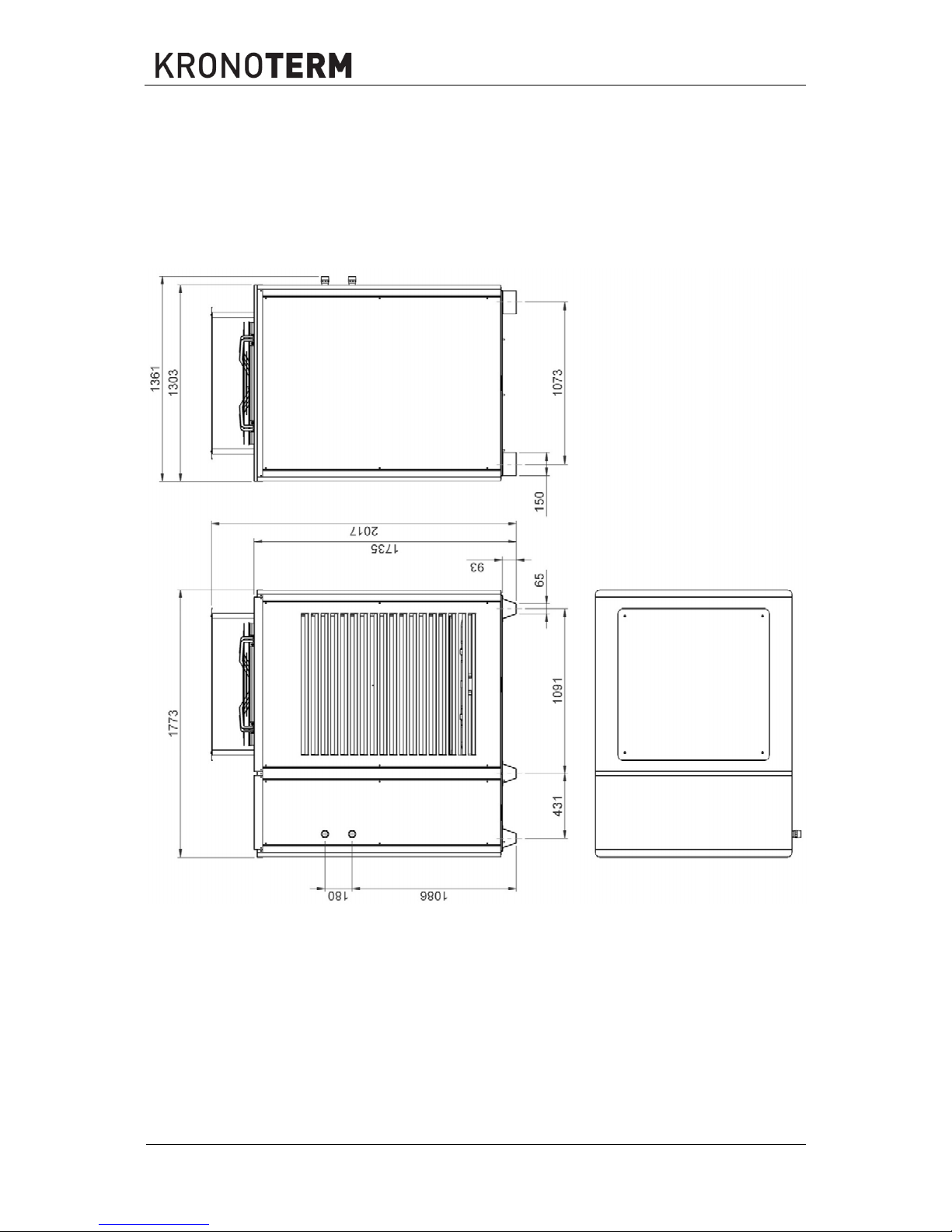
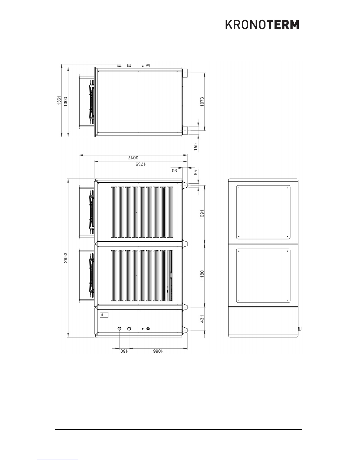
Devices for external installation must be placed on a level concrete foundation (chapter 4.2.4). For exact
position and dimensions of pipe connections, see dimensional drawings of the device (chapter 7.1).
Along with pipes for the hydraulic connection, install also pipes with wire rope (it is advisable to separate
the power / sensors). This wire rope is used to pull the device’s power supply cable from the DHW room
and the communication FTP cable for controlling the device. For the appropriate diameter of the power
cable, see technical data (chapter 7.2).
Make a sink for the condensate forming in the evaporator of the device underneath the concrete
foundation. The sink must be under the frost limit to ensure unobstructed drainage. The pipe for
condensate drainage must be installed lower than the hardware connections of the DHW room and
device. It can also be routed to the rain water sink; in this case freezing of the pipe must be prevented.
WARNING
If the condensate drainage is fed to faecal sewage, a suitable syphon must be installed on
the drainage pipe. Otherwise, the presence of ammonia can lead to corrosion of vital parts
of the device and malfunction of the device.
4.2 Location of the device
CAUTION
The concrete pedestal must carry the weight of the device. See technical
information.
The device must be screwed to the concrete pedestal because of the possibility of
strong gusts of wind.
The device must be levelled
NOTE
It is obligatory to consider the minimal clearance from obstacles for ensuring unobstructed
access for maintenance and service of the device.
NOTE
The location of the device has to be accessible with manual transport devices to ensure
undisturbed delivery of replacement parts and equipment for maintenance and servicing.
Costs connected with hiring special equipment for installing the device, servicing and
maintenance are charged the operator separately and are not subject of the warranty.
The device must not be set up at a location which is subject to stronger and lengthy gusts of wind (i.e.
bora wind); they could obstruct the normal air circulation through the evaporator which could result in
disruptions in operation.
In case the device is installed in the wind direction, it is necessary to install adequate wind protection.
Wind protection must be robust enough to prevent the influence of the wind. The best option is
a concrete or brick version.
The height and width of the wind protection must be at least 150% of the basic dimensions of
the device. Only these dimensions enable adequate wind protection of the device.

Id.: 17-16-26-3017-03 | 6.2017
19
The wind protection must be located at least 3000 mm away from the external unit to ensure
sufficient air flow.
NOTE
The device must be set up in a leeward location.
CAUTION
The device must be placed in such a manner that the external air temperature sensor is on
the shady side.
NOTE
Salt or dust gathering on the outer heat conductor must be regularly cleaned (dust once
yearly and salt in coastal regions at least three times yearly) or rinsed with water.
T
Temperature sensor
20
Id.: 17-16-26-3017-03 | 6.2017
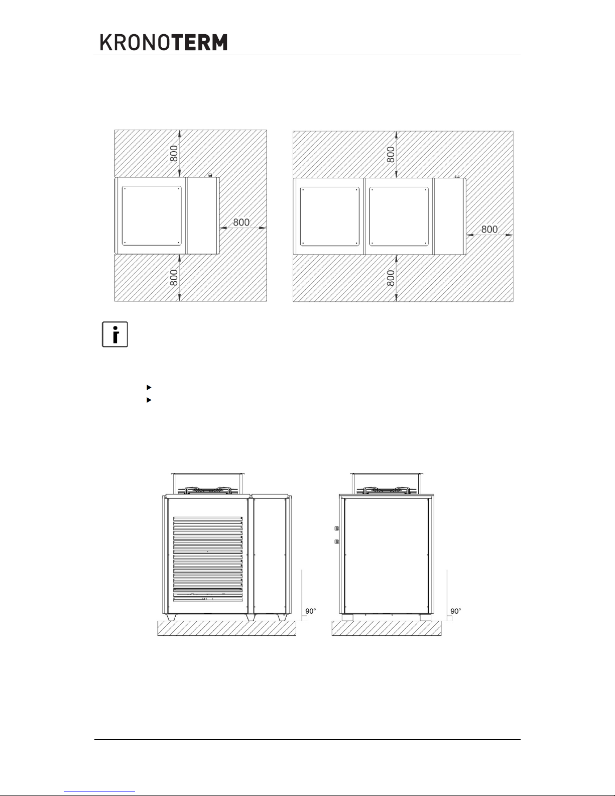
4.2.1 Minimal clearance from the device
Minimal clearances of the external device from walls for seamless operation, maintenance and
servicing.
WPL-45-K1 HT WPL-70-K1 HTT and WPL-90-K1 HTT
NOTE
In case of an insufficient clearance of the device from the building, moisture and rain drops
travelling with the air exhaust on the top of the device can damage the façade.
The clearances for the wall controller unit are listed in the documents:
Instructions for Installing the Basic Wall Control Unit TT3000 and
Instructions for Installing the Expansion Wall Control Unit TT3003.
4.2.2 Levelling of the device
It has to be made sure all the elements installed are placed perpendicularly to the ground as shown in
the scheme below:
Id.: 17-16-26-3017-03 | 6.2017
21
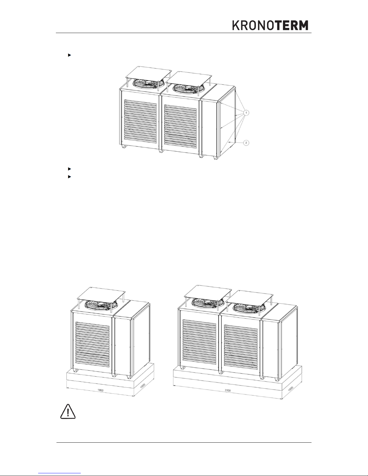
4.2.3 Removal of side
The installation power breakers must be in the “OFF” position.
Unscrew the screws marked with 1 on the right side of the device.
Pull the lower part of the side (2) towards you and disconnect it from the device’s cover.
4.2.4 Concrete pedestal
The installation (connections above or below ground) routed from the DHW room to the device does
not influence the make of the concrete pedestal.
To ensure greater protection against freezing, installation using an underground cable duct is
recommended.
Installation of the concrete pedestal
The reinforced concrete pedestal must be installed on a suitable buffered base. The recommended
minimal edge thickness of the concrete pedestal is given by the design engineer according to the mass
of the device (chapter 7.2).
WPL-45-K1 HT WPL-70-K1 HTT and WPL-90-K1 HTT
CAUTION
The device must be screwed on the left and right side through the supporting legs to the
concrete pedestal because of the possibility of stronger gusts of wind.

22
Id.: 17-16-26-3017-03 | 6.2017
4.3 Hydraulic connection of the device
Connect the external unit to the heating system with water pipes of appropriate dimensions (see
technical data - chapter 7). The pipes have to be insulated with insulation which is at least 13 mm thick
and resistant to weather-proof. The hydraulic connection of the system is made via a transitional pipe
connection on the device.
CAUTION
The water pipes must not be installed alongside the heating in the screed or alongside any
kind of source of heat or cold.
External pipe connection
The pipe connection between the DHW room and the device can be made using two ribbed pipes (A)
or one separate ribbed pipe (B).
A External pipe connection B External pipe connection
P16
Fill with waterproof polyurethane foam, i.e.:
purpen
P20 Ribbed protective pipe min. ɸ 100
P17 Communication cable protective pipe P21 Power cable protective pipe
P18 Pipe - min. DN25 i.e.:(Cu-28, Alumplast-32) P22 Ribbed protective pipe min. ɸ 150
P19 Insulation at least 13 mm
For unobstructed and safe operation it is important to have a heat accumulator. The accumulator is
needed for the hydraulic balancing, ensuring unobstructed flow and defrosting and a longer lifespan of
the device. A larger accumulator ensures a more even temperature of heating and more comfort. The
accumulator is dimensioned to provide at least 10 litres per kW of heating power under the condition of
A2W35.
WARNING
Before connecting the device, it is necessary to rinse the pipe system thoroughly and
remove impurities (hard particles, oils, greases ...).
CAUTION
The closing valve with exhaust has to be installed lower than the pipe connections on the
device.
4.4 Heating system of machine installations
WARNING
The dimensioning of circulation pumps, valves, safety elements and pipes has to be
performed by the designing engineer according to the heating/cooling capacity of the
device.
Id.: 17-16-26-3017-03 | 6.2017
23
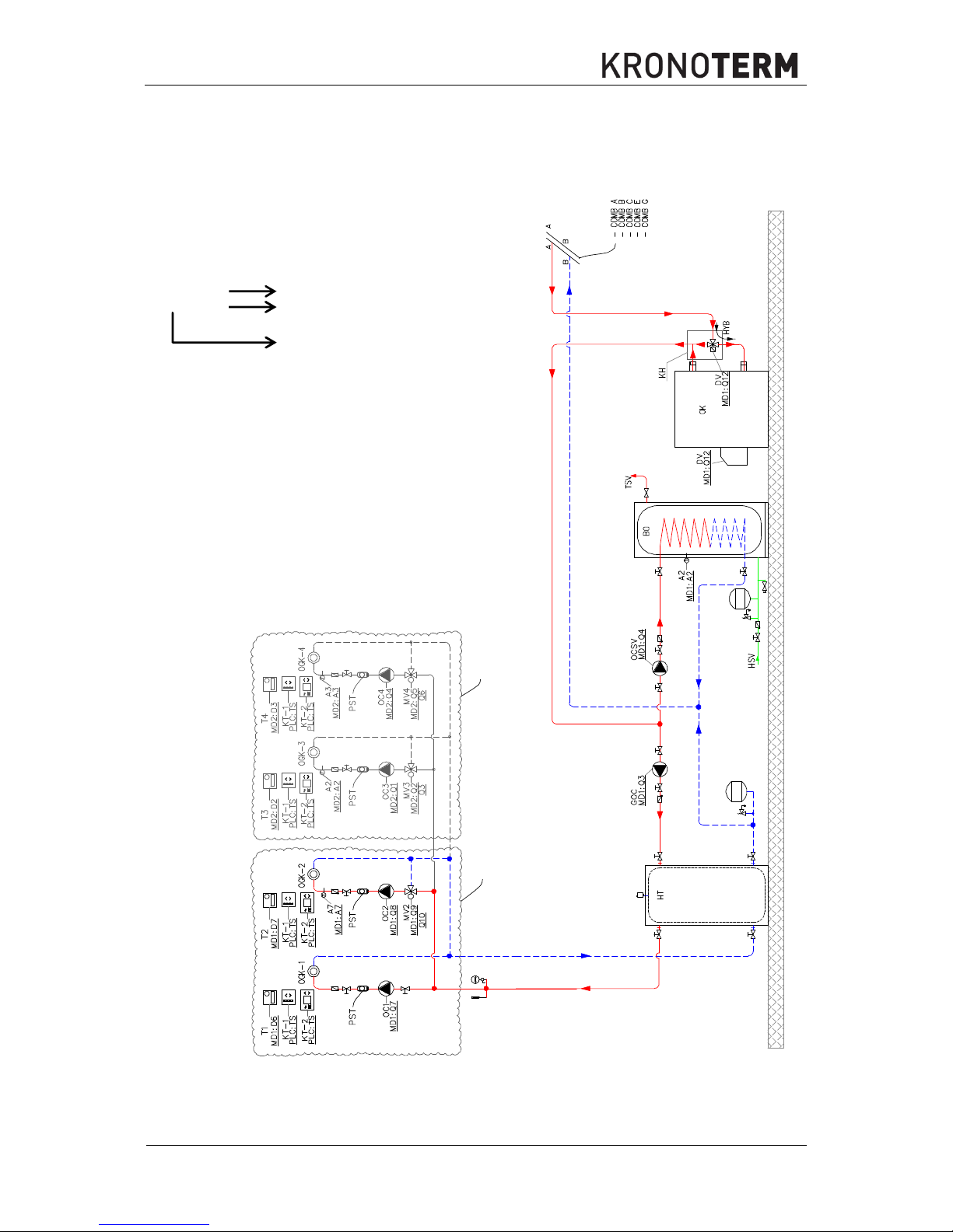
4.4.1 The scheme of the heating system
Below you can see an example of the basic hydraulic and control scheme of the heating system. For
other circuits see The Catalogue of Hydraulic Circuit Diagram.
MD1
MD2
M
M
M
The elements on the scheme are marked in the following
manner:
Legend of reading:
GOC
Mark of the element
MD1:Q3
Mark of the connecting clip on the
input/output module - MD
Mark of the input/output module
24
Id.: 17-16-26-3017-03 | 6.2017
ELEMENTS
CONNECTING
CLIPS
MARK CHARACTERISTICS
COMB A
- G
Connection to various types of heat pumps
A
The device’s supply pipe
B
The device’s return pipe
OK
Current oil DHW
SP
Backup source
HT
Buffer tank for DHW
TSV
Warm sanitary water
BO
Boiler for sanitary water
HSV
Cold sanitary water
OCSV
Circulating pump for DHW
GOC
Main circulation pump
PLC
Processing unit
KT-1
Room temperature corrector KT-1 (can be used in all
heating cycles)
KT-2
Room temperature corrector KT-2 (can be used in all
heating cycles)
TS
Connector on PLC
Q1-Q12
Digital outputs of regulation ~ 230 V (input/output
module MD1 and MD2)
A1-A8
Analogue input (input/output module MD1 and MD2)
D1-D9
Digital input (input/output module MD1 and MD2)
HYB
Switch to hybrid operation
KH
Krono-hybrid
MD1
Basic input/output module 1
T1
Thermostat of heating cycle 1
T2
Thermostat of heating cycle 2
OC1
Circulation pump of heating cycle 1
OC2
Circulation pump of heating cycle 2
MV2
Mixing valve of heating cycle 2
OGK-1
Heating cycle 1
OGK-2
Heating cycle 2
MD2
Expansion input/output module 2
T3
Thermostat of heating cycle 3
T4
Thermostat of heating cycle 4
OC3
Circulation pump of heating cycle 3
OC4
Circulation pump of heating cycle 4
MV3
Mixing valve of heating cycle 3
MV4
Mixing valve of heating cycle 4
OGK-3
Heating cycle 3
OGK-4
Heating cycle 4
PST
Pipe safety thermostat
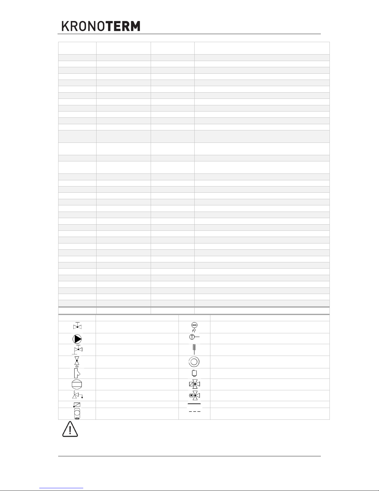
MARK
CHARACTERISTICS
MARK
CHARACTERISTICS
Closing valve
Manometer
Circulation pump
Temperature sensor
Closing valve with exhaust
Thermometer
Drain valve with plug
Consumer of heat / coolness
Cleaning piece
Automatic vent
Expansion tank
3-way switching valve with em drive
Safety valve
3-way mixing valve with em drive
Non-return valve
Supply pipe
Pipe safety thermostat
Return
CAUTION
The supply pipe of each heating cycle must be fitted with an abutment safety thermostat
connected sequentially with the circulation pump to safeguard against the inflow of a
medium of excessive temperature.
Id.: 17-16-26-3017-03 | 6.2017
25
4.4.2 Charging of the heating system
WARNING
Thorough venting of the system has to be ensured. Otherwise, malfunctions in operation
may occur.
CAUTION
An expansion vessel of suitable dimensions must be fitted to the heating system. The
expansion vessel must be dimensioned in accordance with standard EN 12828.
CAUTION
For normal operation of the expansion vessel, it is necessary to perform proper adjustments
of the tank’s working pressure. The settings have to be checked every 12 months.
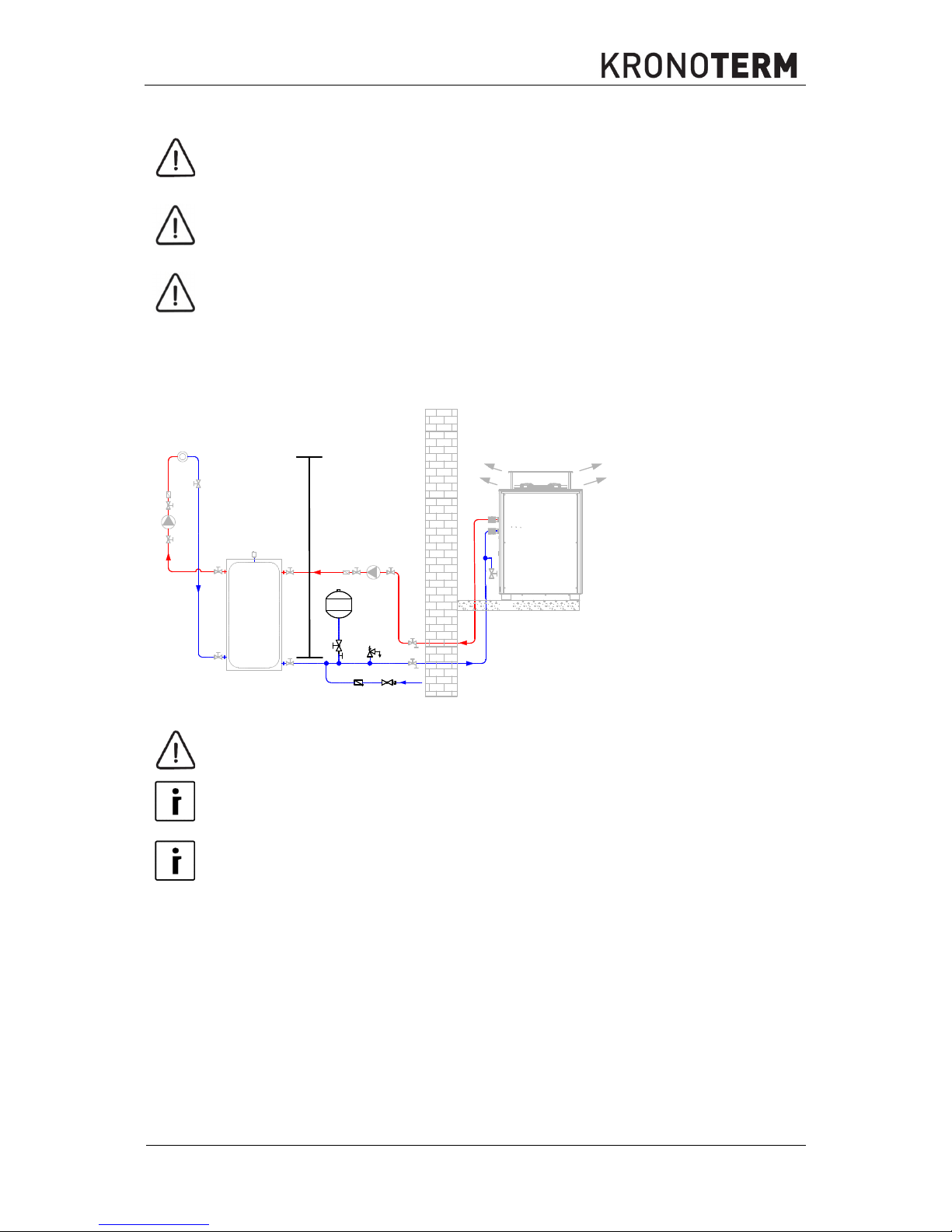
The pressure settings of the expansion vessel and filling the hating system
B
C
D
A
H[m]
psv
A - Filling the system.
B - Expansion vessel.
C - Ball valve with
exhaust.
D - Air filling valve.
H - Height of the heating
system.
psv - Pressure of the
safety valve.
CAUTION
Consider the maximal operational pressure of the vessel.
NOTE
Unsuitable pre-load of the expansion vessel with the pressure p0 is the reason for incorrect
operation of the heating system.
NOTE
The dimensions of the expansion vessel must be in accordance with standard EN 12828.

26
Id.: 17-16-26-3017-03 | 6.2017
Setting the pressure for the expansion vessel p0
Before filling the system with water, check and set the pressure p0.The expansion vessel is
factory set to the pressure specified on the standard label. For correct operation of the system,
set the pressure p0 according to the equation below. The filling must not exceed the maximal
operational pressure specified on the serial label of the expansion vessel.
Calculate the p0 pressure value with the help of the equation:
ሾ
MPaሿ=
ுሾ୫
ሿ
ଵ
+ 0,02 ሾMPaሿ,
ቀ
ሾ
barሿ=
ுሾ୫
ሿ
ଵ
+ 0,2 ሾbarሿቁ.
CAUTION
If the calculation shows a pressure lower than 0,1 MPa (1 bar), set the pressure of the
expansion vessel to 0,1 MPa (1 bar).
p0 [MPa (bar)] – pressure in the expansion vessel,
p
0min
[MPa (bar)] – minimal allowed pressure of the heating system,
p
0max
[MPa (bar)] – maximal allowed pressure of the heating system,
H [m] – Height of the heating system.
Set the amount of pressure in the expansion vessel by releasing or supplementing dry nitrogen.
Record the new value of the pressure p0 on the serial label.
Open the ball valveof the expansion vessel carefully, open the vents and close the drain.
Filling the heating system
Use the filling valve to fill the system with water of suitable quality (with anti-corrosion additives,
etc.) to the pressure pF.
ி
ሾ
MPaሿ=
ሾ
MPaሿ+ 0,03 ሾMPaሿ ,
ሺ
ி ሾbarሿ=
ሾ
barሿ+ 0,3 ሾbar
ሿ
ሻ
.
pF [MPa (bar)] – filling pressure,
p0 [MPa (bar)] – pressure in the expansion vessel.
Filling the system to the final pressure
The final pressure of the system is determined by heating the system to the maximal heating
temperature (thermal degassing).
Turn off the circulation pumps, open the vents and vent the system.
Fill the system up to the final pressure which is 0,05 MPa (0.5 bar) lower than the venting
pressure of the safety valve.
ሾ
MPaሿ≤
ୱ୴
ሾ
MPaሿ− 0,05 ሾMPaሿ,
ሺ
ሾ
barሿ≤
ୱ୴
ሾ
barሿ− 0,5 ሾbar
ሿ
ሻ
.
pE – the final pressure of the system,
pSV – the pressure of the safety valve.
4.4.3 Preparing the heating system – secondary
Prepare the system according to one of the recommended hydraulic schemes (Catalogue of Hydraulic
Wiring Diagrams) which is specified by the manufacturer of the device. This is the only way to ensure
reliable and effective operation of the device. After connecting the device to the heating system, it is
necessary to examine all circulating pumps and electric motor valves if they function correctly.

Id.: 17-16-26-3017-03 | 6.2017
27
The device must be connected to the heating system via rubber compensator or flexible pipes. The
latter must not be under tension in final position, this would worsen the devices noise and vibration
protection. In extreme cases this can also lead to damage to the device.
Quality of heating water
Maximal allowed content of individual substances in the heating water and the influence of these on the
heat exchanger are presented in the table below. It is not allowed to use heating water which contains
any substance in concentrations which cause corrosion in the heating system (influence “-”). It is also
not allowed to use heating water which contains two or more substances in concentrations which could
cause corrosion in the heating system (influence “0”).
TYPE OF PRESENT
SUBSTANCE
UNIT CONCENTRATION
INFLUENCE TO THE HEAT
CONDUCTOR
Organic sediment
mg / L
0
Ammonia NH3 mg / L
< 2
1 to 20
> 20
+
0
-
Chloride mg / L
< 300
> 300
+
0
Allowed water hardness
°dH
5 – 10
Electrical conductivity µS / cm
< 10
10 to 500
> 500
0
+
-
Iron (Fe) removed mg / L
< 0.2
> 0.2
+
0
Free carbonic acid mg / L
< 5
5 to 20
> 20
+
0
-
Manganese (Mn) removed mg / L
< 0.1
> 0.1
+
0
Nitrates (NO3) removed mg / L
< 100
> 100
+
0
pH value mg / L
< 7.5
7.5 to 9
> 9
0
+
0
Oxygen mg / L
< 2
> 2
+
0
Hydrogen sulphide (H2S) mg / L
< 0.05
> 0.05
+
-
HCO3- / SO
4
2
- mg / L
> 1
< 1
+
0
Hydrogen carbonate mg / L
< 70
70 to 300
> 300
0
+
0
Aluminium (Al) removed mg / L
< 0.2
> 0.2
+
0
Sulphates mg / L
< 70
70 to 300
> 300
+
0
-
Sulphite (SO
3
) mg / L
< 1 +
Chlorine (gas) (Cl2) mg / L
< 1
1 to 5
> 5
+
0
-
Table: Influence of various aggressive substances in the heating water on the stability of stainless
copper welded plate transmitters. (+ = no influence, 0 = danger of corrosion, - = corrosion - use not
permitted).

28
Id.: 17-16-26-3017-03 | 6.2017
CAUTION
The heating system has to be filled with water with the hardness between 5 °dH and 10
°dH. Malfunctions of the device because of water hardness are not covered by the warranty.
The quality of the water used in the heating system is very important. The water from the water supply
is mostly not suitable for use in the heating system. To ensure adequate water hardness you must built
the water softener into the system.
The heating systems must not be filled with dirty or corrosive water. The heating water must be prepared
by adding anti-corrosion and anti-biological agents as well as agents against algae.
CAUTION
The water used for heating DHW via the built-in heat exchanger in the buffer tank for DHW
has to be in accordance with the requirements of standard VDI 2035 and must not contain
microorganisms. The heating system has to be filled with soft water which has been added
anti-corrosion and antibacterial agents for preventing corrosion. Before filling the heating
system has to be cleaned of all impurities.
The heating system has to be thoroughly vented. You must prevent air, including diffusion
air entering the device.
NOTE
To prevent damage to the components of the hydraulic system, we recommend the
additional installation of SpiroVent RV2 air (micro-bubble) venting system.
The presence of micro bubbles in the system eventually forms larger bubbles which in time
can cause corrosion of the system, system component malfunction and operation
disturbance.
In new systems, the impurities are a consequence of welding, soldering, dirty pipes (oil, grease), etc.
In case the impurities start accumulating in the device this can worsen the flow and heat transfer, in
worst cases also freezing of water in the heat exchanger and consequently the destruction of the device.
WARNING
To protect the device from intake and accumulation of dirt in the heat exchanger you must
install the strainer on the return line, before entry into the device.
WARNING
A galvanic disconnection between individual elements of the heating system (i.e. boiler,
container ...) is obligatory.
In the case of using grey steel pipes in the heating system, it is necessary to degrease them (the interior
of the pipe) before connecting them to the heat pump.

Id.: 17-16-26-3017-03 | 6.2017
29
4.4.4 Condensate drainage
The device has one opening on the bottom side (WPL-45-K1 HT) or two openings (WPL-70-K1 HTT
and WPL-90-K1 HTT) for condensate drainage which is collected in the condensation vessel of the
device. The condensate accumulates on the evaporator from the air or is a consequence of evaporator
defrosting. The position of the drain(s) is shown on the pictures below (A).
WPL-45-K1 HT WPL-70-K1 HTT and WPL-90-K1 HTT
A
A
The heating cable with thermostat is factory connected to the device. After connecting the condensate
pipe to the drains (A), the heating cable with thermostat must be inserted into it. The position of this
thermostat must be on the coolest part of the condensate pipe which leads into the drain. Turn the
thermostat which comes out the heating cable for 180° and insert it back into the pipe so that only 10
cm of the loop is sticking out.
Thermostat at the end of the heating cable. 10 cm leftover heating cable which you have to
insert back into the condensate pipe.

30
Id.: 17-16-26-3017-03 | 6.2017
4.5 Electrical connection
Connect the external device to the mains according to the instructions described in this chapter.
CAUTION
Connecting the device to the electrical network has to be performed in accordance with the
standards for connecting devices to the electrical network. The device has to be connected
to the electrical network via the power supply cut-off which is installed into the electrical
installation under the regulations in force. The power supply cut-off has to separate all
contacts under the regulations of the overvoltage category III - minimal spacing between
contacts is 3 mm.
DANGER
The final electrical connection, before commissioning can only be performed by the person
authorised by the manufacturer to ensure the correct and efficient operation of the device.
IT IS STRICTLY PROHIBITED FOR UNAUTHORISED PERSONS TO TAMPER WITH
THE ELECTRICAL CONNECTION OF THE DEVICE.
D
ANGER
The device must be connected to the mains, which has a built-in RCD residual-current
device, switch type A.
CAUTION
The device must be connected to the mains with a cable with an appropriate diameter. The
electrician defines the diameter of the cable according to the installation method, distance
of the device from the main electrical cabinet and the power of the device.
4.6 Removal of the lid of the control unit
Remove the side of the device (see
chapter 4.2.3).
Unscrew the screw on the
lid of the control unit
cabinet.
Open the controller cabinet
towards you.

Id.: 17-16-26-3017-03 | 6.2017
31
4.7 Connecting the external unit
In the scope of the external unit, you have to connect the electrical cabinet with:
External unit power cable.
Communication FTP cable between external and internal control unit.
Constituent elements of the external electrical cabinet
Relay panel MD1
Motor protection
Fuses
Relays
Contactors
EEV drivers
Connecting clips
Current limiter
Transformer
The procedure of connecting the external electrical cabinet is described below.
32
Id.: 17-16-26-3017-03 | 6.2017
4.7.1 Power cable connection of the external unit
DANGER
Connecting the device to the power source can only be performed by a qualified installer in
a voltage-free state.
CAUTION
The cable must be routed through the cord anchorage installed before the connecting
terminals in the indoor unit. Make sure the cable connected in the indoor unit is relieved
from strain.
CAUTION
Wrong dimensioning of the power cable or too weak terminal fuses of the device could lead
to an overload of the safety elements on the power grid of the building which could lead to
overheating of the electrical installation. Follow the requirements listed in this manual.
CAUTION
The communication cable must not be laid together with energy cables (in accordance with
good engineering practise and regulations).
CAUTION
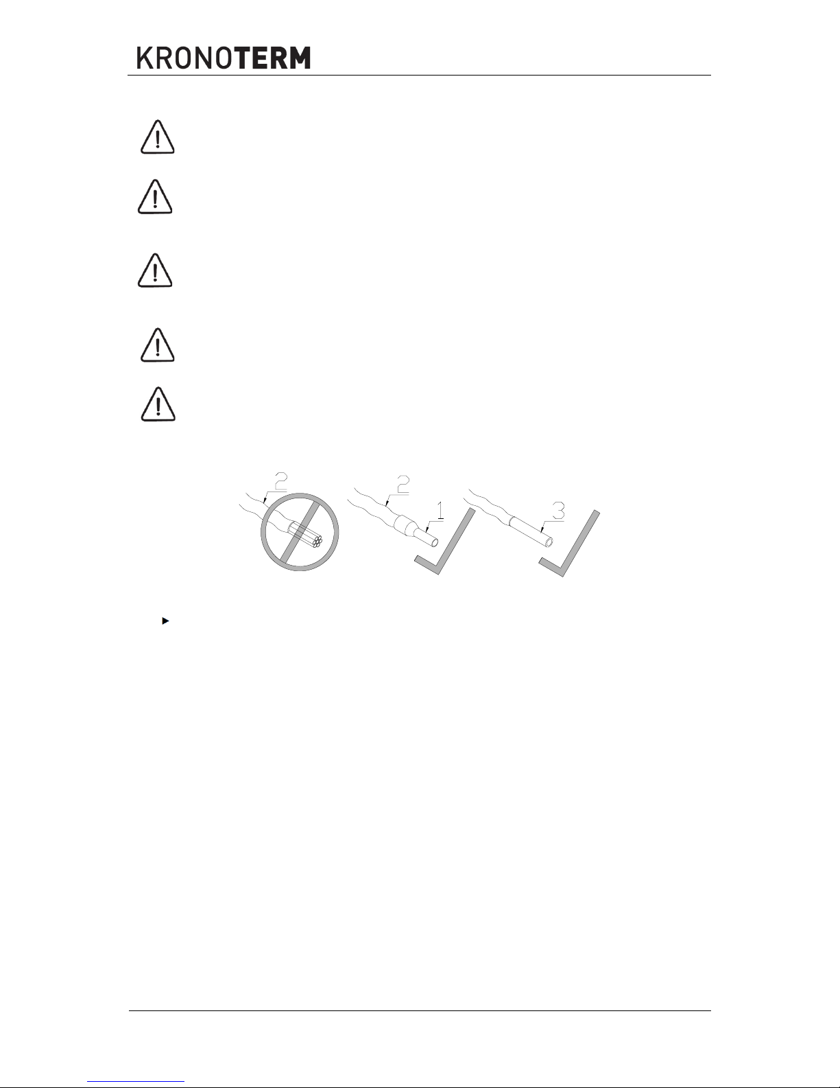
In case of connecting the multi-wire flexible cable to the connecting clamp, it always has to
have a necking die at the end.
1 Necking die 2
Multi-wire flexible cable
3 Massive single-wire cable
To connect to connecting clamps of the device, use cables with necking dies or a massive
single-wire cable.

Id.: 17-16-26-3017-03 | 6.2017
33
Connecting clips of the supply cable
Connect the electrical supply (3N ~ 400V / 50Hz) to the connecting clips L1, L2, L3, N and PE
( ). For choosing the appropriate diameters of the cables, see technical data (chapter 7.2).
Clip PE ( ) (yellow-green cable) / clip N (blue cable) / clips L1 L2, L3 (3 x black or black, grey, brown
cable).
supply cable
util. cable
4.7.2 The connection of the communication FTP cable to the external unit
The communication cable is intended for communication between the external MD3 and the internal
MD1 input/output module.
After installing the plated cable between the external and internal device, use four cables and
connect them to the connecting terminals A+ / B- / 12 V / GND in external device.
A+
B-
GND
12V
X7
In the case of prefabricated FTP cable, connect the cable pair wires 1, 2 to A+, 2, 3 to B-, 4, 5
to 12 V and GND to 7, 8.
For a detailed description of connecting the FTP cable of the internal unit, see:
Manual for Installation, Use and Maintenance for Installing the Basic or Expansion Wall
Control Unit TT3000, TT3003.
34
Id.: 17-16-26-3017-03 | 6.2017
4.8 Connecting the internal device
See:
Manual for Installation, Use and Maintenance for Installing the Basic or Expansion
Control Unit TT3000, TT3003.
4.9 Spatial corrector
See:
Instructions for installing and using KT-1 or
Instructions for installing and using KT-2
5. Commissioning of the device
After professional installation, the authorised contractor has to perform the commissioning of the device.
CAUTION
The commission can only be performed by a person authorised by the manufacturer! If the
commission is performed by an unauthorised person, the warranty is not recognised.
Management of the device must be performed in accordance with current instructions for use.
CAUTION
Before the commission it is necessary all the required tasks and inspections from the tasks
for commission.
Id.: 17-16-26-3017-03 | 6.2017
35
6. MAINTENANCE
The device must be visually inspected once a year. The electrical and hardware installation of the device
as well as the state of the evaporator have to be inspected. In case irregularities and impurities are
detected on the evaporator or clotting of the channels between the lamellas, contact the authorised
maintenance worker to perform cleaning.
CAUTION
The servicing and maintenance of the device can only be performed by a person authorised
by the manufacturer. In case of a malfunction, first contact the installer who installed the
device.
6.1 Cleaning the water filter
NOTE
Cleaning of water filters on the return into the device is advised to be performed at least
once yearly.
CAUTION
A blocked water purifying component and magnetic filter can lead to a malfunction of the
device or incorrect functioning of the device. In case the display displays a warning of flow
malfunction (”Caution, flow!”).
6.2 Monitoring the pressure in the heating system
NOTE
Periodically, once yearly, check the water temperature in the heating system.
NOTE
In case the pressure falls (i.e. Leakage of the system) the display displays a warning of flow
malfunction (”Caution, flow!”).
6.3 Cleaning of the heat conductors
6.3.1 Cleaning of the heating system (water side)
Residue of grease and sealants in pipes can pollute the condenser of the device up to a point where
cleaning is necessary. In this case the authorised person should perform the cleaning with a mild
solution (up to 5 %) of phosphorous acid which should be heated to room temperature. The condenser
has to be completely disconnected from the heating system and rinsed with diluted phosphorous acid
in the opposite direction of normal flow.
After cleaning the condenser has to be rinsed thoroughly with an agent neutralising the acid detergent
so as to prevent contamination of the heating system.
CAUTION
Acid detergents should be used carefully, instructions of the manufacturer and
environmental regulations must be followed. The cleaning can only be performed by a
qualified person.
If any doubts about using the detergents arise, consult with the manufacturer of the detergent.
36
Id.: 17-16-26-3017-03 | 6.2017
6.3.2 Cleaning the heat source (air side)
The air lamella heat exchanger must be checked at least 1 x yearly. In case of impurities in the air dust
can accumulate on the surface of the heat exchanger which worsens heat exchange in the air. In this
case the evaporator has to be cleaned. The cleaning has to be performed by a qualified person.
DANGER
Before cleaning, make sure the device is turned off and in a voltage free state.
WARNING
Do not touch the vaporizer with your hands so as not to cut yourself on the lamellas.
Cleaning the lamella conductor should be done with an air jet which blows away dust particles on the
lamella heat conductor. The evaporator can also be cleaned using a soft water spray or purpose
cleaning agents intended for cleaning the lamellas of the conductor. Be careful not to deform the
lamellas and cause uneven air flow and degraded performance of the device.
WARNING
Heating the air heat conductor (evaporator) can only be performed by a qualified person.
The manufacturer is not liable for damage to the user or device. All damage to the device
caused by inappropriate cleaning are not covered by the warranty.
6.4 Disturbances in the operation
In case of a malfunction during the operation of the device, the display of the TERMOTRNIC controller
displays the warning “Caution, malfunction”.
Find the malfunction description in the manual. For error correction call the installer who installed the
device.
CAUTION
In case of heavy snowfall, it has to me bade sure the snow does not obstruct the airflow
through the evaporator.
Id.: 17-16-26-3017-03 | 6.2017
37
In case the device is installed in an environment where temperatures can drop under the freezing point,
there is a chance the water in the device can freeze. In this case draining the water from the device
must be enabled or the system must be filled with anti-freeze.
CAUTION
In case of low external temperatures under 0 °C and a power outage longer than 2 hours,
the water must be drained from the device.
Example of installing drainage valves.
A
C
B
A Valve with exhaust
B External device
C Exhaust valve installed in the device
CAUTION
In case of low external temperatures, do not cut the device off from the power supply, this
would disable the operation of the anti-freeze programme. There is a risk of machine
breakage.
38
Id.: 17-16-26-3017-03 | 6.2017
7. Technical data
7.1 Device dimension drawings
7.1.1 WPL-45-K1 HT
Id.: 17-16-26-3017-03 | 6.2017
39
7.1.2 WPL-70-K1 HTT and WPL-90-K1 HTT
40
Id.: 17-16-26-3017-03 | 6.2017
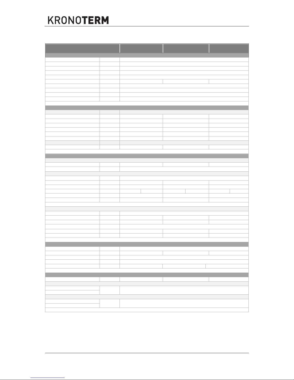
7.2 Technical data
Device WPL-45-K1 HT WPL-70-K1 HTT WPL-90-K1 HTT
Version
Heat source External air
Heat sink Water
1)
Controller TERMOTRONIC 3000 WEB
Device placement External
Placement of the controller un. Internal
Compressor 1 x scroll 2 x scroll 2 x scroll
Defrosting Passive (with ambient air) + Active (change of cooling cycle direction)
Electric heater /
Soft start-up Yes (optional)
Circulation pump, secondary /
Capacity
Heating
Heating power / electrical power / COP
2)
A7/W35 kW / kW / -
44,8 / 9,7 / 4,62 70,3 / 15,6 / 4,51 86,8 / 19,7 / 4,40
A2/W35 kW / kW /
38,3 / 9,3 / 4,13 60,5 / 15,0 / 4,02 74,1 / 18,8 / 3,94
A7/W55 kW / kW / - 40,9 / 13,2 / 3,10 64,5 / 21,4 / 3,01 79,3 / 26,7 / 2,97
A2/W55 kW / kW / - 33,8 / 12,3 / 2,74 53,6 / 20,1 / 2,67 65,6 / 25,0 / 2,62
A-10/W35 kW / kW / -
28,7 / 8,4 / 3,41 46,1 / 13,9 / 3,31 55,7 / 17,3 / 3,22
A-10/W55 kW / kW / - 26,8 / 11,2 / 2,39 44,1 / 18,1 / 2,43 54,0 / 22,7 / 2,38
Cooling
Cooling power / electrical power / EER
3)
A35/W12-7 kW / kW / - 33,6 / 11,5 / 2,92
52,8 / 18,9 / 2,79
66,0 / 23,8 / 2,77
Electrical data
External and internal unit
Max. electrical power kW 17.6 27.9 34.5
Z
max
11)
Ω
0.015
External unit
Rated voltage 3N~ 400 V; 50 Hz
Max. operational current A 28.6 47.6 56.6
Max. electrical power kW 17.1 27.4 34.0
Current of blocked rotor (LRA) A 127 149
10)
127 149
10)
127 149
10)
Fuses
12)
A 3 x 32 3 x 50 3 x 63
Electrical power cable
4*)
mm
2
5 x 6 5 x 10 5 x 10
Internal unit
5)
Rated voltage ~ 230 V; 50 Hz
Max. operational current A 2.3 2.3 2.3
Max. electrical power kW 0.5 0.5 0.5
Z
max
11)
Ω
0.015
Fuses A 1 x C16 1 x C16 1 x C16
Electrical power cable
4)
mm2
3 x 2.5 3 x 2.5 3 x 2.5
Cooling system
Coolant - type R407C
Coolant - quantity kg 32.7 58.0 61.0
Max. operational pressure MPa 2.9
Oil - type POE (Emkarte RL 32 3MAF)
Oil - quantity l 4.14 8.00 8.28
Primary side (heat source)
- air
Nominal flow m3/h
10,400 20,200 20,800
Heating
Range of operation -
°C -23 / 40
min. / max. air temperature
Cooling
Range of operation -
°C 10 / 40
min. / max. air temperature
Id.: 17-16-26-3017-03 | 6.2017
41
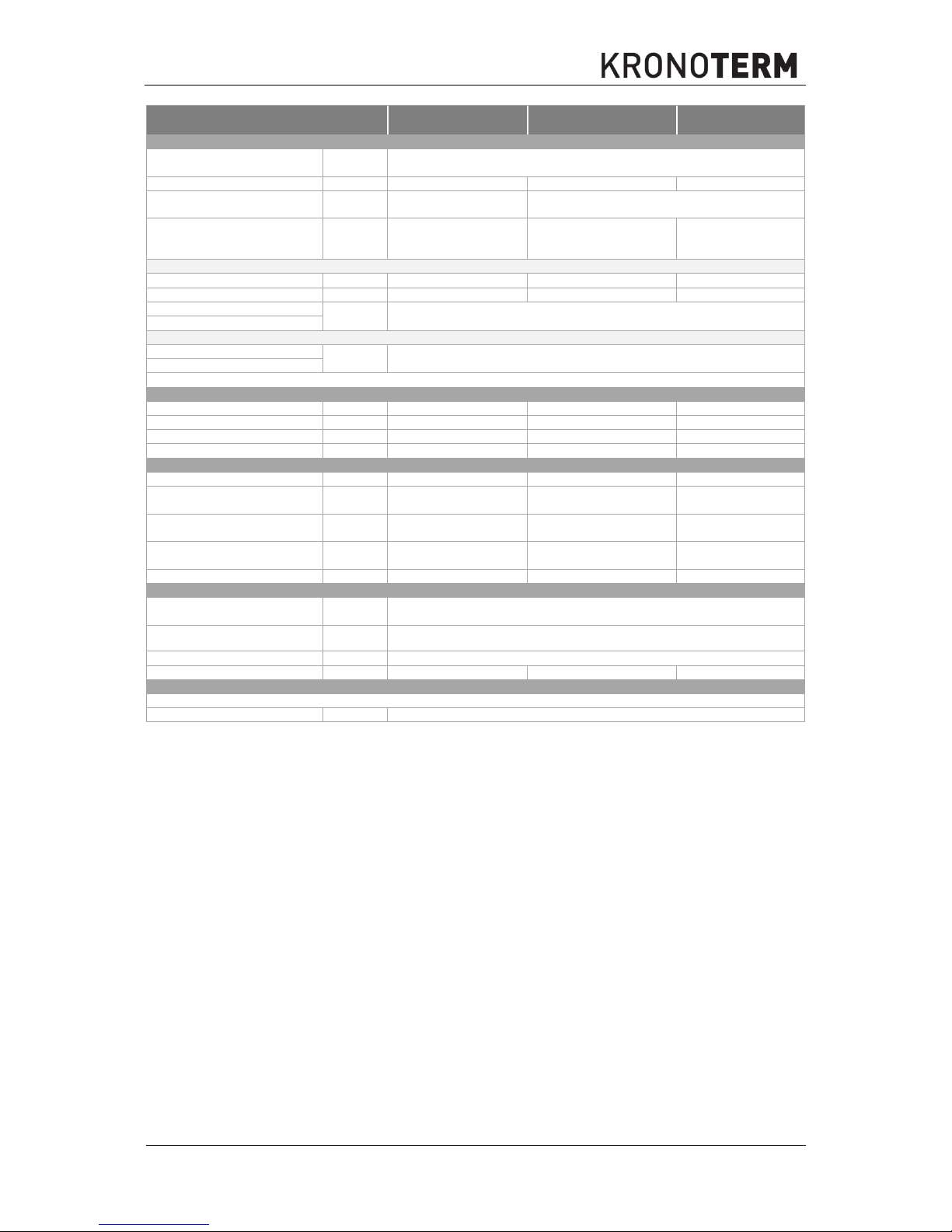
Device WPL-45-K1 HT WPL-70-K1 HTT WPL-90-K1 HTT
Secondary side (heat sink)
- water
1)
Min. / Max. pressure in the
system
MPa 0,05 / 0,3 (0,5 / 3 bar)
Pipe connections G 1.1/2” (ext. dev.)
G 2” (ext. dev.)
G 2” (ext. dev.)
Recommended main circulation
pump
6)
WILO Stratos PARA 30/1-12 Stratos PARA 50/1-12
Recommended dimensions of
pipes leading to
the device
7)
DN 40 50 65
Heating
Rated flow
6)
m3 / h
7.4 12.1 14.9
Pressure drop at rated flow kPa 27 29 37
Range of operation -
°C 25 / 63
min. / max. water temperature
Cooling
Range of operation -
°C 7 / 25
min. / max. water temperature
Dimensions and mass
Dimensions (W x H x D)
mm 1773 x 2017 x 1361 2953 x 2017 x 1361 2953 x 2017 x 1361
Transport mass kg 805 1325 1366
Net mass kg 802 1315 1361
Noise
Level of sound power dB (A)
75 76 77
The level of sound pressure
at a distance of 1 m
dB (A)
67 68 69
The level of sound pressure
at a distance of 5 m
dB (A)
53 54 55
The level of sound pressure
at a distance of 10 m
dB (A)
47 48 49
Communication
Connection between ext. and
inter. unit
FTP cable / LiYCY 4 x 0.75 mm
2
Connection to BMS MODBUS protocol (UTP cable – connection RJ45) – RS 485
Connection to the internet
8)
UTP 5e cable - connection RJ45 - Ethernet
Miscellaneous
Protection class
External unit IPX4
1)
A water solution of up to 35 % of propylene-glycol or ethylene-glycol can be used as secondary medium.
Use of other substances is not permitted or the manufacturer of the device must be consulted prior to use.
Requirements regarding water quality are listed in the installation manual in the chapter “Preparation of
the Hydraulic System”. The requirements must be taken into account!
2)
COP (Coefficient of Performance) is a card for performance efficiency of the device, the heating number
which is a quantity without unit. Computer-wise COP is the ratio between the energy gained - heat (in
cooling it is heat taken away) and electrical energy needed for the functioning of the device.
3)
EER (Energy Efficiency Ratio) is an abbreviation for the coefficient of the cooling energy efficiency.
Mathematically EER is the ratio between the effective cooling power and effective electrical power in [kW].
4)
With the cable we have taken into account laying B2 from the table A.52.4 – IEC 60364-5-52. The cable
in the installation pipe is fixed to the wall. The dimensions of the electrical cables must always be checked
or determined by the designing engineer of electrical installations.
4*)
With the cable we have taken into account laying C from the table A.52.4 – IEC 60364-5-52.
The
cable in the installation pipe is fixed onto the wall. The dimensions of the electrical cables must always be
checked or determined by the designing engineer of electrical installations.
5)
Joint maximal load (circulation pumps, electronic valves ...) which can be connected to or powered by the
internal unit, must not exceed 500 W. Higher consumers (i.e. pumps) should have their own supply.

42
Id.: 17-16-26-3017-03 | 6.2017
6)
The circulation pump must be dimensioned in such a way that it ensures rated voltage through the heat
pump.
7)
Applies to pipe connections of adequate dimensions and joint distance of up to 20 m. Pipe dimensions
and types of pumps must always be verified or determined by the designing engineer of electrical
installations. Circulation pumps must be dimensioned in such a way so as to ensure rated voltage (see
table) through the device.
8)
Connection to the internet is not necessary for the operation of the device but it is necessary for remote
control through the Home Cloud service. It is also advisable for faster troubleshooting of the device’s
operation.
9)
For internal HM devices, see technical data for HM.
10)
Compressor 1 + compressor 2 (In1 + LRA2)
11)
After connecting the device it is necessary to acquire the guarantee or consult the operator of the
distribution network that the impedance of the network is lower than Z
max
. This way the device will operate
within acceptable limits of disruptions. Otherwise it is necessary to connect the device to the network
using a soft start device.
12)
Circuit breaker with “slow” characteristics for devices with very high inrush current.
7.3 Range of operation
Devices can operate inside the operation ranges shown below.
7.3.1 Heating mode
10
20
30
40
50
60
70
-30 -20 -10 0 10 20 30 40 50
Temp. of outlet water [°C]
Air temperature [°C]

Id.: 17-16-26-3017-03 | 6.2017
43
7.3.2 Cooling mode
7.3.3 Pressure drop through the device
WPL-45-K1 HT
WPL-70-K1 HTT WPL-90-K1 HTT
0
10
20
30
0 10 20 30 40 50
Temp. of outlet water [°C]
Air temperature [°C]
0
20
40
60
80
100
120
140
0 4 8 12 16
Pressure drop through
the HP [kPa]
Water flow [m3/h]
0
20
40
60
80
100
120
0 4 8 12 16 20 24
Pressure drop through
the HP [kPa]
Water flow [m3/h]
0
20
40
60
80
100
120
140
0 4 8 12 16 20 24 28
Pressure drop through
the HP [kPa]
Water flow [m3/h]

44
Id.: 17-16-26-3017-03 | 6.2017
7.4 Noise
Noise is any kind of sound which causes a disturbance, interferes with a person’s work and causes
harm to health and well-being. Individuals can have different reactions to the same noise at different
occasions. Perception of sound also depends on the current mood of an individual.
Every device which operates with fluctuation is a source of sound. The spread of sound or noise is also
affected by walls and other obstacles in the in the vicinity of the device. This is why the correct choice
of location of the device is very important.
Sound emissions of the device into the surroundings are described by physical quantities such as sound
power and sound pressure. Both physical quantities are given in the dimensionless unit decibel (dB).
Level of sound power (L)
The power level of sound is the energy of sound which the device emits into the environment per
second. It is a quantity which is used for the basic comparison of various sound sources and for
determining whether the machine or device complies with the regulations and standards for noise
radiation. The power of sound is independent on the environment in which the source is located.
The reference sound power is 10
-12
W.
Example: The sound power of the human breathing is 10
-11
W or 10 dB.
The sound power of whispering is 10
-10
W or 20 dB.
The level of sound pressure (p)
The level of sound pressure is the changing pressure of sound waves which a sound produces. Sound
pressure is detected or heard as volume. It depends on the environment where the source is located
and the distance of the listener to the source of the sound.
The standard reference sound pressure in the air is 20 µPa (10-6 Pa). This is the sound auditory
threshold at the sound frequency of 1 kHz.
Example: The sound pressure of normal human speech at a distance of 1 m ranges from 2 to 20 mPa
(10-3 Pa) or from 40 to 60 dB.
Decibel (dB, dB (A))
A decibel is the unit without dimension with which we express the ratio between the changing quantity
and the fixed reference. Among others it is also used for measuring the intensity of sound or sound
energy. It is calculated on a logarithmic scale which means that if the ratio increases by 3 dB, the sound
energy doubles, if it increases by 10 dB, the sound energy increases by a factor of 10 and if it increases
by 20 dB, the sound energy increases by a factor of 100, etc.
Example:
The level of sound pressure of the device is measured in a free sound field at three different distances.
For precise data on the sound pressure of your device see technical data 7.2.
Noise
Level of sound power of the device dB (A) 57
Level of sound pressure at a distance of
1 m
dB (A) 49
Level of sound pressure at a distance of
5 m
dB (A) 43
Level of sound pressure at a distance of
10 m
dB (A) 29

Id.: 17-16-26-3017-03 | 6.2017
45
The source of sound of the device
Level of sound power [dB]
Noise
A pocket watch in the bedroom 20 Very quiet
Air conditioning in an office 40 quiet
Heating heat pump 57 Loud
Normal speech 60 Loud
Gas burner 75 Very loud
Traffic, loud radio 80 Very loud
Plane motor 140 Painful
r = 1 m
r = 10 m
r = 5 m

46
Id.: 17-16-26-3017-03 | 6.2017
7.5 Legend of data label
Mark
Characteristics
Maximal compressor electrical power.
Maximal electrical heater power.
Maximal additional load electrical power (circulation pump, etc.).
+ +
Maximal electrical power of the device (compressor + electric heater + additional
load).
Cooling circuit.
DHW.
Heat exchanger in the DHW.
Heating system.
Internal device (Hydraulic module or Termotronic).
External device (WPL or WPLV).
Device mass.
Note about handling waste electronic equipment.
CE sign for the compliance of the device with CE directives.

Id.: 17-16-26-3017-03 | 6.2017
47
8. Notes
_________________________________________________________________________________
_________________________________________________________________________________
_________________________________________________________________________________
_________________________________________________________________________________
_________________________________________________________________________________
_________________________________________________________________________________
_________________________________________________________________________________
_________________________________________________________________________________
_________________________________________________________________________________
_________________________________________________________________________________
_________________________________________________________________________________
_________________________________________________________________________________
_________________________________________________________________________________
_________________________________________________________________________________
_________________________________________________________________________________
_________________________________________________________________________________
_________________________________________________________________________________
_________________________________________________________________________________
_________________________________________________________________________________
_________________________________________________________________________________
_________________________________________________________________________________
_________________________________________________________________________________
_________________________________________________________________________________
_________________________________________________________________________________
_________________________________________________________________________________
_________________________________________________________________________________
_________________________________________________________________________________
_________________________________________________________________________________
_________________________________________________________________________________
_________________________________________________________________________________
_________________________________________________________________________________
_________________________________________________________________________________
_________________________________________________________________________________
_________________________________________________________________________________
_________________________________________________________________________________
_________________________________________________________________________________
_________________________________________________________________________________
_________________________________________________________________________________
_________________________________________________________________________________
_________________________________________________________________________________
_________________________________________________________________________________
_________________________________________________________________________________
_________________________________________________________________________________
_________________________________________________________________________________
_________________________________________________________________________________
_________________________________________________________________________________
_________________________________________________________________________________
_________________________________________________________________________________
_________________________________________________________________________________
_________________________________________________________________________________

The headquarters of the company and place of
production
Kronoterm d.o.o.
Trnava 5e
3303 Gomilsko
Tel.: (00386) 3 703 16 20 | Fax: (00386) 3 703 16 33 | Web-page: www.kronoterm.com |
E-mail: info@kronoterm.com | Customer support and service.: (00386) 3 703 16 26 |
E-mail.: servis@kronoterm.com
 Loading...