

Kronoterm WPL-18-K1 HK 3F E, WPL-16-K1 HK 3F E, WPL-18-K1 HT 3F E, WPL-18-K1 HT, WPL-23-K1 HT Service Instructions Manual
...Page 1

Service instructions
For the Air-Water Heat Pump
WPL-16-K1 NT (WPL-16-K1 NT/HK 3F E)
WPL-18-K1 HT (WPL-18-K1 HT/HK 3F E)
WPL-23-K1 HT (WPL-23-K1 HT/HK 3F E)
WPL-31-K1 HT (WPL-31-K1 HT/HK 3F)
ID.: 17-17-16-4517-01 / 4.2017
ENG
SERVICE
REVISION
SER. NO. OF
INTRODUCED CHANGE
DATE OF INTRODUCED
CHANGE
EXCEPTIONS
01 216330314 28.9.2016
Page 2

©Termo-tehnika, d.o.o.
ID.: 17-17-16-4517-01
1
4.2017
Service manual - Version 01 / 4.2017
Printed in Slovenia, copyright: Termo-tehnika, d. o. o.
This document is copyrighted. Any use outside the provisions of the copyright law without the
permission of Termo-tehnika d.o.o. is illegal and punishable by law. All previous versions of
this document are void. We reserve the right to make changes and mistakes in print.
Page 3

©Termo-tehnika, d.o.o.
ID.: 17-17-16-4517-01
2
4.2017
Index
Index 2
1. Serial number structure ........................................................................................ 3
2. The position of connections and dimensions ..................................................... 4
3. Technical data ....................................................................................................... 4
4. Removal of front cover ......................................................................................... 4
5. Cooling piping diagram ........................................................................................ 5
5.1 WPL-16-K1 ............................................................................................................. 5
5.2 WPL-18-K1, WPL-23-K1, WPL-31-K1 ..................................................................... 7
6. Electrical wiring diagram ...................................................................................... 9
6.1 WPL-16-K1 in WPL-18-K1 ....................................................................................... 9
6.2 WPL-23-K1 in WPL-31-K1 ......................................................................................11
7. Components .........................................................................................................13
7.1 Bill of materials WPL-16-K1 NT (WPL-16-K1 NT/HK 3F E) ....................................13
7.2 Bill of materials WPL-18-K1 (WPL-18-K1 HT/HK 3F E) ..........................................14
7.3 Kosovnica WPL-23-K1 (WPL-23-K1 HT/HK 3F E) ..................................................16
7.4 Kosovnica WPL-31-K1 (WPL-31-K1 HT/HK 3F) .....................................................17
7.5 Position on the device ............................................................................................19
Page 4
©Termo-tehnika, d.o.o.
ID.: 17-17-16-4517-01
3
4.2017
1. Serial number structure
The serial number is structured to include the following information:
T - type of device/sales group
YY - year of manufacture
WW - calendar week of device manufacture
XXXX - serial number of the product in the production year.
T YY WW XXXX (written without spaces)
Example: 215460001
2 15 46 0001
HEATING HP Year of manufacture (2015) Calendar year of man.
Serial no. in the year (0001,
0002, 0003...)
Page 5

©Termo-tehnika, d.o.o.
ID.: 17-17-16-4517-01
4
4.2017
2. The position of connections and dimensions
3. Technical data
See Installation manual for the air-water heat pump ID: 17-15-45-2567-xx.
4. Removal of front cover
To access the electrical and cooling part of the device, first remove the sides as shown in the
Installation manual for the air-water heat pump ID: 17-15-45-2567-xx.
1
Removable lid for connecting water in the installation mode V1 (on the bottom
of the device)
3 Supply pipe for heating
4 Return pipe for heating
Page 6
©Termo-tehnika, d.o.o.
ID.: 17-17-16-4517-01
5
4.2017
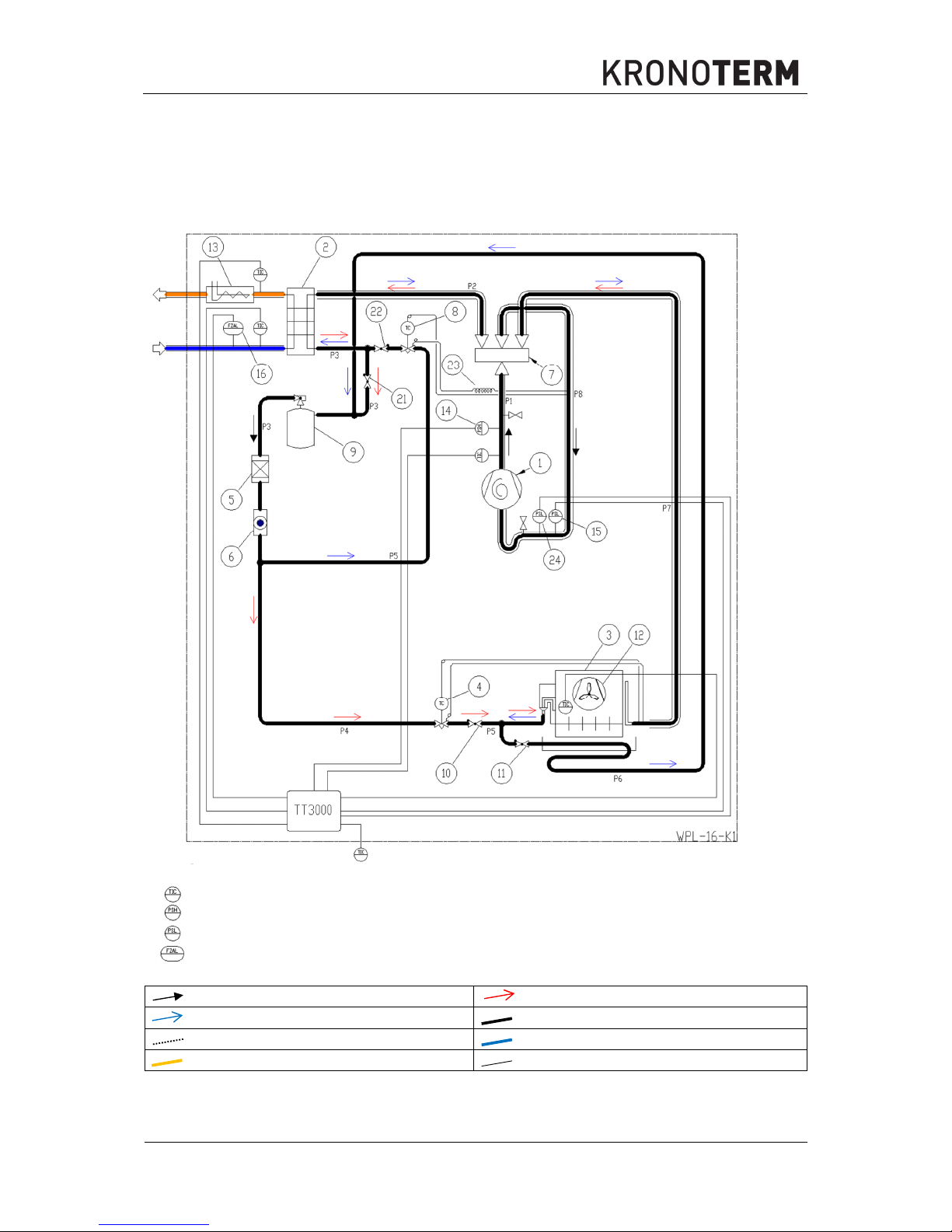
5. Cooling piping diagram
5.1 WPL-16-K1
Temperature sensor
HP (high pressure) switch
LP (low pressure) switch
Flow switch
Permanent direction
Heating
Defrosting / Cooling
Refrigerant
Control and data Return pipe for heating
Supply pipe for heating Unit limit
Page 7

©Termo-tehnika, d.o.o.
ID.: 17-17-16-4517-01
6
4.2017
1 Compressor 14 HP switch
2 Condenser 15 LP switch
3 Evaporator 16 Flow switch
4
TXV (thermostatic expansion valve),
heating
17 Economiser
5 Filter, dehydrator 18 TXV, Eco
6 Moisture indicator 19 Electromagnetic valve
7 4-Way valve 20 Moisture indicator Eco
8 TXV, cooling 21 Check valve
9 Tank 22 Check valve
10 Check valve 23 Capillary pipe
11 Check valve 24 LP switch
12 Fan 25 Closing ball valve
13 Electrical heater 26 Closing ball valve
Tabel of pipe diamteters
WPL 16
WPL 18
WPL 23 WPL 31
P1
Φ16 x 1 Φ16 x 1 Φ22 x 1 Φ22 x 1
P2
Φ28 x 1 Φ28 x 1 Φ35 x 1 Φ35 x 1
P3
Φ12 x 1 Φ12 x 1 Φ16 x 1 Φ16 x 1
P4
Φ12 x 1 Φ12 x 1 Φ16 x 1 Φ16 x 1
P5
Φ12 x 1 Φ16 x 1 Φ16 x 1 Φ16 x 1
P6
Φ12 x 1 Φ16 x 1 Φ16 x 1 Φ16 x 1
P7
Φ28 x 1 Φ28 x 1 Φ35 x 1 Φ35 x 1
P8
Φ28 x 1 Φ28 x 1 Φ35 x 1 Φ35 x 1
P9
/ Φ10 x 1 Φ10 x 1 Φ10 x 1
P10
/ Φ12 x 1 Φ16 x 1 Φ16 x 1
Page 8
©Termo-tehnika, d.o.o.
ID.: 17-17-16-4517-01
7
4.2017
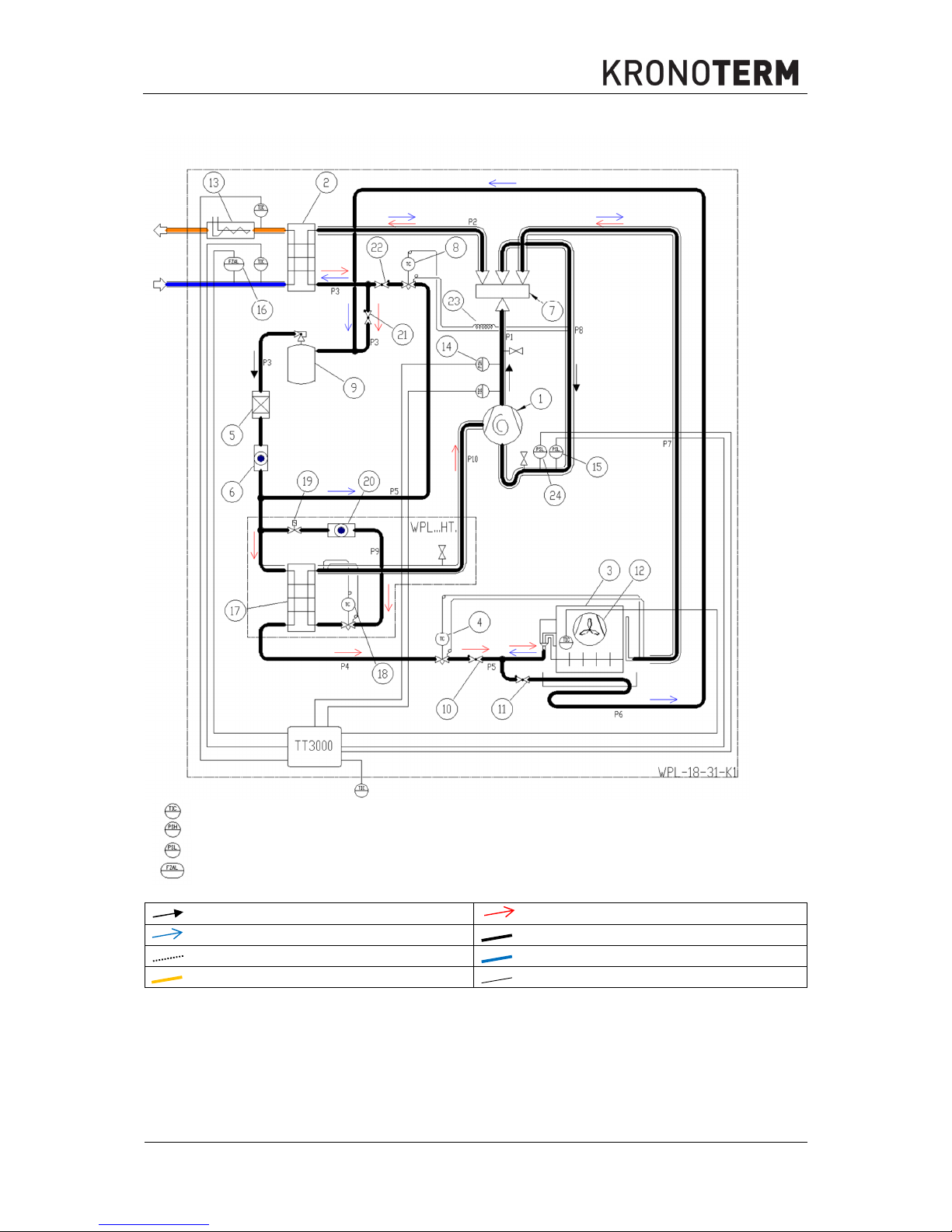
5.2 WPL-18-K1, WPL-23-K1, WPL-31-K1
Temperature sensor
HP (high pressure) switch
LP (low pressure) switch
Flow switch
Permanent direction
Heating
Defrosting / Cooling
Refrigerant
Control and data Return pipe for heating
Supply pipe for heating Unit limit
Page 9
©Termo-tehnika, d.o.o.
ID.: 17-17-16-4517-01
8
4.2017
1 Compressor 14 HP switch
2 Condenser 15 LP switch
3 Evaporator 16 Flow switch
4
TXV (thermostatic expansion valve),
heating
17 Economiser
5 Filter, dehydrator 18 TXV, Eco
6 Moisture indicator 19 Electromagnetic valve
7 4-Way valve 20 Moisture indicator Eco
8 TXV, cooling 21 Check valve
9 Tank 22 Check valve
10 Check valve 23 Capillary pipe
11 Check valve 24 LP switch
12 Fan 25 Closing ball valve
13 Electrical heater 26 Closing ball valve
Tabel of pipe diamteters
WPL 16
WPL 18
WPL 23 WPL 31
P1
Φ16 x 1 Φ16 x 1 Φ22 x 1 Φ22 x 1
P2
Φ28 x 1 Φ28 x 1 Φ35 x 1 Φ35 x 1
P3
Φ12 x 1 Φ12 x 1 Φ16 x 1 Φ16 x 1
P4
Φ12 x 1 Φ12 x 1 Φ16 x 1 Φ16 x 1
P5
Φ12 x 1 Φ16 x 1 Φ16 x 1 Φ16 x 1
P6
Φ12 x 1 Φ16 x 1 Φ16 x 1 Φ16 x 1
P7
Φ28 x 1 Φ28 x 1 Φ35 x 1 Φ35 x 1
P8
Φ28 x 1 Φ28 x 1 Φ35 x 1 Φ35 x 1
P9
/ Φ10 x 1 Φ10 x 1 Φ10 x 1
P10
/ Φ12 x 1 Φ16 x 1 Φ16 x 1
Page 10
©Termo-tehnika, d.o.o.
ID.: 17-17-16-4517-01
9
4.2017
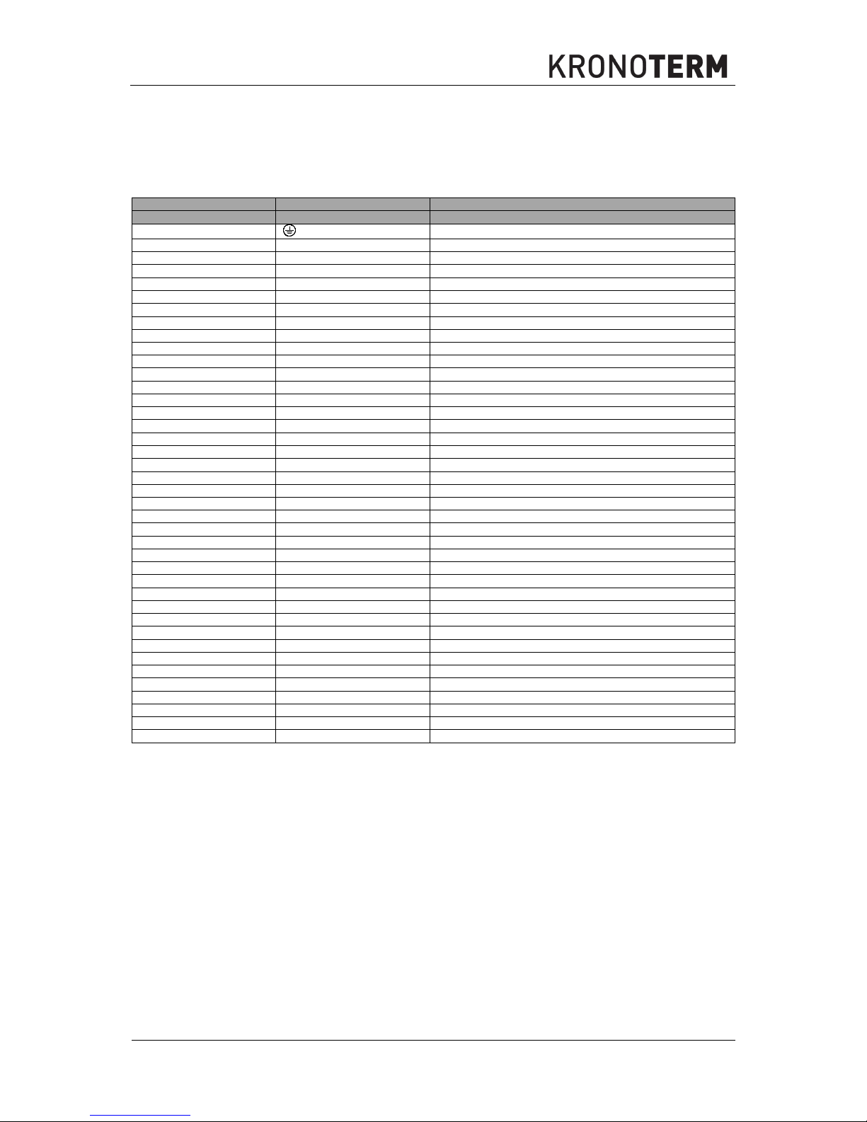
6. Electrical wiring diagram
6.1 WPL-16-K1 in WPL-18-K1
MARK OF THE ELEMENT
CONNECTING CLIPS
DESCRIPTION
X1
Connecting clip
, PE
Grounding wire
N
Neutral wire
L1, L2, L3
Connecting phases of the supply cable
4,5
Safety thermostat
RV 6
Reversible valve
7
Connecting clip ~ 230 V
N
Neutral wire
GND
Functional grounding
F2, F3, F4, F5
Circuit Breakers
MD3
Input/output module MD3
JMP
Position of jumper (on second position)
M1 Q1
Heat source
Q2
Connecting compressor 1.
Q5
Additional source – electrical flow heater
RV Q6
Reversible valve
Q11
Valve for cooling
A1
Return temperature sensor
A3
Compressor temperature sensor
A4
Evaporator temperature sensor
A5
Temperature sensor for outdoor temperature
A6
Temperature sensor of the supply pipe
D1
Overvoltage protection
D2
High-pressure switch
NT1 D3
Low-pressure switch 1 in heating mode
NT2 D3
Low-pressure switch 2 in cooling mode
PS D4
Flow switch
GND
Functional grounding
TE1
Comuniction with the PLC
EG
Electrical flow heater
C1, C3
Contactors
R1, R2
Relays
EMV
Electromagnetic valve
KF
Phase control, voltage relay
M 1~
One-phase motor
M 3~
Three-phase motor
M1
Fan
M2
Compressor 2
TV
Thermal switch
GK1, GK2, GK3
Heating cables
WPL18
-HT
Only in high-temperature model
Page 11

©Termo-tehnika, d.o.o.
ID.: 17-17-16-4517-01
10
4.2017
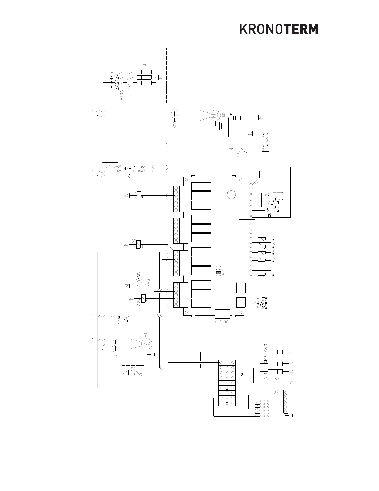
3~ 400V 50Hz
WPL18 HT
TE1
TE2
GND
12V
PWM +
Q13
12V
D1 D2 D3 D4 D5 D6 D7 D8
12V
SK Q10 Q11 Q12
A1
5V 5V
GND
A2
SK Q7 Q8 Q9
SK Q4 Q5 Q6
SK Q1 Q2 Q3
A3
5V 5V
GND
A4
A5
5V 5V
GND
A6
A7
5V 5V
GND
A8
MD3 (MBIO12)
PWM -
~230V ~230V ~2 30V
~230V ~230V ~230 V
~230V ~230V ~230 V
~230V ~230V ~230 V
L ~ 230V
TV
Picture 1: El. Wiring diagram WPL-16-K1 in WPL-18-K1
Page 12
©Termo-tehnika, d.o.o.
ID.: 17-17-16-4517-01
11
4.2017
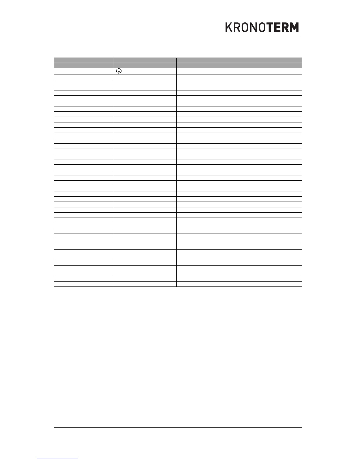
6.2 WPL-23-K1 in WPL-31-K1
MARK OF THE ELEMENT
CONNECTING CLIPS
DESCRIPTION
X1
Connecting clip
, PE
Grounding wire
N
Neutral wire
L1, L2, L
3
Connecting phases of the supply cable
4,5
Safety thermostat
RV 6
Reversible valve
7
Connecting clip ~ 230 V
N
Neutral wire
GND
Functional grounding
F2, F3, F4, F5
Circuit Breakers
MD3
Input/output module MD3
JMP
Position of jumper (on second position)
M1 Q1
Heat source
Q2
Connecting compressor 1.
Q5
Additional source – electrical flow heater
RV Q6
Reversible valve
Q11
Valve for cooling
A1
Return temperature sensor
A3
Compressor temperature sensor
A4
Evaporator temperature sensor
A5
Temperature sensor for outdoor temperature
A6
Temperature sensor of the supply pipe
D1
Overvoltage protection
VT D2
High-pressure switch
NT1 D3
Low-pressure switch 1 in heating mode
NT2 D3
Low-pressure switch 2 in cooling mode
PS D4
Flow switch
GND
Functional grounding
TE1
Comuniction with the PLC
EG
Electrical flow heater
C1, C2,
C3
Contactors
R1, R2
Relays
EMV
Electromagnetic valve
KF
Phase control, voltage relay
M 1~
One-phase motor
M 3~
Three-phase motor
M1
Fan
M2
Compressor 2
TV
Thermal switch
Komp. zščita
Compressor protection
GK1, GK2, GK3
Heating cables
WPL23
-HT
Only in high-temperature model
Page 13
©Termo-tehnika, d.o.o.
ID.: 17-17-16-4517-01
12
4.2017
WPL 23 HT
TE1
TE2
GND
12V
PWM +
Q13
12V
D1 D2 D3 D 4 D5 D6 D7 D8 12V
SK Q10 Q11 Q12
A1
5V 5V
GND
A2
SK Q7 Q8 Q9
SK Q4 Q5 Q6
SK Q1 Q2 Q3
A3
5V 5V
GND
A4
A5
5V 5V
GND
A6
A7
5V 5V
GND
A8
MD3 (MBIO12)
PWM -
~230V ~ 230V ~230V
~230V ~230V ~230V
~230V ~230V ~230V
~230V ~ 230V ~230V
3~ 400V 50Hz
L ~ 230V
TV
WPL 23 HT
Slika 2: El. Vezalna shema WPL-23-K1 in WPL-31-K1
Page 14

©Termo-tehnika, d.o.o.
ID.: 17-17-16-4517-01
13
4.2017
7. Components
7.1 Bill of materials WPL-16-K1 NT (WPL-16-K1 NT/HK 3F E)
POS Ident
Name
Quantity
EM
2222000072346 WPL-16-K1 NT (WPL-16-K1 NT/HK 3F E) 1
1 2222000020668
COMPRESSOR
1
PIECE
2 2222000043872
HEAT CONDUCTOR - CONDENSER
1
PIECE
3 2222000021078
EVAPORATOR
1
PIECE
4.1 2222000077976
THERMO-EXPANSION VALVE - HE
1
PIECE
4.2 2222000078010
JET OF THE THERMOSTATIC EXPANSION VALVE - HE
1
PIECE
4.3 /
/
/
/
5 22220000060695
DEHYDRATOR
1
PIECE
6 /
/
/
/
7 2222000078966
4 SIDE VALVE
1
PIECE
8.1 2222000077976
THERMOSTATIC EXPANSION VALVE - COOL
1
PIECE
8.2 2222000078034
JET OF THE THERMOSTATIC EXPANSION VALVE - COOL
1
PIECE
8.3 /
/
/
/
9 2222000022839
TANK
1
PIECE
10 2222000057398
CHECK VALVE 12MM
1
PIECE
11 2222000057398
CHECK VALVE 12MM
1
PIECE
12 2222000008284
FAN
1
PIECE
13 2222000082345
ELECTRICAL HEATER 6,0 kW
1
PIECE
14 2222000034597
PRESSURE SWITCH Y 29/25
1
PIECE
15 2222000050702
PRESSURE SWITCH Y 3,0/4,0
1
PIECE
16 2222000034269
FLOW SWITCH
1
PIECE
17 / / /
/
18 / / /
/
19 / / /
/
20 22220000085360 MOISTURE INDICATOR 1
PIECE
21 2222000057398 CHECK VALVE 12MM 1
PIECE
22 2222000057398 CHECK VALVE 12MM 1
PIECE
23 2222000000301 CAPILLARY PIPE 3
PIECE
24 2222000058647 PRESSURE SWITCH Y 0,3/1,0 1
M
25 2222000023348 RELAY PANEL MBIO12 1
PIECE
26 22220000022235 CONTACTOR KNL 12-01/220/240V 1
PIECE
26 22220000002688 CONTACTOR KNL 12-10/220/240V 1
PIECE
28 / / /
/
29 / / /
/
30 / / /
/
31 2222000004903 RELAY 1
PIECE
32 2222000041489 RELAY BASE 1
PIECE
33 2222000047405 PHASE CONTROLLER 1
PIECE
34 2222000037062 HEATING CABLE 200W 2
PIECE
Page 15

©Termo-tehnika, d.o.o.
ID.: 17-17-16-4517-01
14
4.2017
35 2222000050658
PT SENSOR
5
PIECE
36 2222000045944
4-WAY VALVE COIL
1
/
37 2222000022594
OIL HEATER
1
PIECE
38 2222000065652
ELECTRONICS LID
1
PIECE
39 2222000032982
VENT VALVE
1
PIECE
40 2222000072872
FRONT LOWER SMALL PANEL
2
PIECE
41 2222000072889 FRONT LOWER BIG PANEL 2
PIECE
42 2222000072896 ROOF 1
PIECE
43 2222000072902 FRONT UPPER PANEL 1
PIECE
44 2222000072919 SIDE UPPER PANEL 2
PIECE
45 2222000072926 BACK UPPER PANEL 1
PIECE
46 2222000072858
FAN PANEL
1
PIECE
47 2222000072933
CONDENSATE BASIN
1
PIECE
48 2222000072827
BOTTOM
1
PIECE
49 2222000037031
HEATING CABLE 60W
1
PIECE
50 / / /
PIECE
7.2 Bill of materials WPL-18-K1 (WPL-18-K1 HT/HK 3F E)
POS Ident
Name
Quantity
EM
2222000072421 WPL-18-K1 HT (WPL-18-K1 HT/HK 3F E) 1
1 2222000032661
COMPRESSOR
1
PIECE
2 2222000049348
HEAT CONDUCTOR - CONDENSER
1
PIECE
3 2222000021078
EVAPORATOR
1
PIECE
4.1 2222000077952
THERMO-EXPANSION VALVE - HE
1
PIECE
4.2 2222000077969
JET OF THE THERMOSTATIC EXPANSION VALVE - HE
1
PIECE
4.3 /
/
/
/
5 22220000060695
DEHYDRATOR
1
PIECE
6 2222000085582
MOISTURE INDICATOR - ECO
1
PIECE
7 2222000078966
4 SIDE VALVE
1
PIECE
8.1 2222000077976
THERMOSTATIC EXPANSION VALVE - COOL
1
PIECE
8.2 2222000078034
JET OF THE THERMOSTATIC EXPANSION VALVE - COOL
1
PIECE
8.3 /
/
/
PIECE
9 2222000022839
TANK
1
PIECE
10 2222000072780
CHECK VALVE 16MM
1
PIECE
11 2222000057398
CHECK VALVE 12MM
1
PIECE
12 2222000008284
FAN
1
PIECE
13 2222000082345
ELECTRICAL HEATER 6,0 kW
1
PIECE
14 2222000034597
PRESSURE SWITCH Y 29/25
1
PIECE
15 2222000050702
PRESSURE SWITCH Y 3,0/4,0
1
PIECE
16 2222000034269
FLOW SWITCH 1250L/h
1
PIECE
17 2222000017439 HEAT CONDUCTOR - ECONOMISER 1
PIECE
18.1 2222000077983
THERMO-EXPANSION VALVE - ECO
1
PIECE
Page 16

©Termo-tehnika, d.o.o.
ID.: 17-17-16-4517-01
15
4.2017
18.2 2222000077990
JET OF THE THERMO-EXPANSION VALVE - ECO
1
PIECE
19 2222000033583 ELECTROMAGNETIC VALVE 1
PIECE
20 2222000085360 MOISTURE INDICATOR 1
PIECE
21 2222000057398 CHECK VALVE 12MM 1
PIECE
22 2222000057398 CHECK VALVE 12MM 1
PIECE
23 2222000000301 CAPILLARY PIPE 3
M
24 2222000058647 PRESSURE SWITCH Y 0,3/1,0 1
PIECE
25 2222000023348 RELAY PANEL MBIO12 1
PIECE
26 2222000002688 CONTACTOR KNL 12-01/220/240V 1
PIECE
27 2222000016951 CONTACTOR KNL 12-10/220/240V 1
PIECE
28 / / /
/
29 / / /
/
30 / / /
/
31 2222000004903 RELAY 2
PIECE
32 2222000041489 RELAY BASE 2
PIECE
33 2222000047405 PHASE CONTROLLER 1
PIECE
34 2222000037062 HEATING CABLE 200W 2
PIECE
35 2222000050658
PT SENSOR
5
PIECE
36 2222000045944
4-WAY VALVE COIL
1
PIECE
37 2222000022594
OIL HEATER
1
PIECE
38 2222000065652
ELECTRONICS LID
1
PIECE
39 2222000032982
VENT VALVE
1
PIECE
40 2222000072872
FRONT LOWER SMALL PANEL
2
PIECE
41 2222000072889 FRONT LOWER BIG PANEL 2
PIECE
42 2222000072896 ROOF 1
PIECE
43 2222000072902 FRONT UPPER PANEL 1
PIECE
44 2222000072919 SIDE UPPER PANEL 2
PIECE
45 2222000072926 BACK UPPER PANEL 1
PIECE
46 2222000072858
FAN PANEL
1
PIECE
47 2222000072933
CONDENSATE BASIN
1
PIECE
48 2222000072827
BOTTOM
1
PIECE
49 2222000037031
HEATING CABLE 60W
1
PIECE
50 /
/
/
/
Page 17

©Termo-tehnika, d.o.o.
ID.: 17-17-16-4517-01
16
4.2017
7.3 Kosovnica WPL-23-K1 (WPL-23-K1 HT/HK 3F E)
POS Ident
Name
Quantity
EM
2222000072445 WPL-23-K1 HT (WPL-23-K1 HT/HK 3F E) 1
1 2222000033170
COMPRESSOR
1
PIECE
2 2222000049348
HEAT CONDUCTOR - CONDENSER
1
PIECE
3 2222000062972
EVAPORATOR
1
PIECE
4.1 2222000077976
THERMO-EXPANSION VALVE - HE
1
PIECE
4.2 2222000078010
JET OF THE THERMOSTATIC EXPANSION VALVE - HE
1
PIECE
4.3 /
/
/
/
5 2222000047603
DEHYDRATOR
1
PIECE
6 2222000023171
MOISTURE INDICATOR - ECO
1
PIECE
7 2222000006815
4 SIDE VALVE
1
PIECE
8.1 2222000029548
THERMOSTATIC EXPANSION VALVE - COOL
1
PIECE
8.2 2222000028978
JET OF THE THERMOSTATIC EXPANSION VALVE - COOL
1
PIECE
8.3 2222000041076
BASE OF THERMOSTATIC EXPANSION VALVE - COOL
1
PIECE
9 2222000022839
TANK
1
PIECE
10 22220000072780
CHECK VALVE 16MM
1
PIECE
11 22220000072780
CHECK VALVE 16MM
1
PIECE
12 2222000033767
FAN
1
PIECE
13 2222000082345
ELECTRICAL HEATER 6,0 kW
1
/
14 222200034597
PRESSURE SWITCH Y 29/25
1
PIECE
15 2222000050702
PRESSURE SWITCH Y 3,0/4,0
1
PIECE
16 2222000045074
FLOW SWITCH
1
PIECE
17 2222000017439 HEAT CONDUCTOR - ECONOMISER 1
PIECE
18.1 2222000077983
THERMO-EXPANSION VALVE - ECO
1
PIECE
18.2 2222000077990
JET OF THE THERMO-EXPANSION VALVE - ECO
1
PIECE
19 2222000033583 ELECTROMAGNETIC VALVE 1
PIECE
20 2222000013783 MOISTURE INDICATOR 1
PIECE
21 22220000072780 CHECK VALVE 16MM 1
PIECE
22 22220000072780 CHECK VALVE 16MM 1
PIECE
23 2222000000301 CAPILLARY PIPE 3
M
24 2222000058647 PRESSURE SWITCH Y 0,3/1,0 1
PIECE
25 2222000023348 RELAY PANEL MBIO12 1
PIECE
26 2222000002688 CONTACTOR KNL 12-01/220/240V 2
PIECE
27 / / /
/
28 2222000030452 CONTACTOR KNL 22 220/240 V 1
/
29 / / /
PIECE
30 2222000008925 SWITCH MS 1
PIECE
31 2222000004903 RELAY 2
PIECE
32 2222000041489 RELAY BASE 2
PIECE
33 2222000047405 PHASE CONTROLLER 1
PIECE
34 2222000037062 HEATING CABLE 200W 2
PIECE
35 2222000050658
PT SENSOR
5
PIECE
Page 18

©Termo-tehnika, d.o.o.
ID.: 17-17-16-4517-01
17
4.2017
36 2222000045944
4-WAY VALVE COIL
2
PIECE
37 2222000054885
OIL HEATER
1
PIECE
38 2222000065652
ELECTRONICS LID
1
PIECE
39 2222000032982
VENT VALVE
1
PIECE
40 2222000072872
FRONT LOWER SMALL PANEL
2
PIECE
41 2222000072889 FRONT LOWER BIG PANEL 2
PIECE
42 2222000072896 ROOF 1
PIECE
43 2222000073008 FRONT UPPER PANEL 1
PIECE
44 2222000072919 SIDE UPPER PANEL 2
PIECE
45 2222000072926 BACK UPPER PANEL 1
PIECE
46 2222000072995
FAN PANEL
1
PIECE
47 2222000072933
CONDENSATE BASIN
1
PIECE
48 2222000072827
BOTTOM
1
PIECE
49 2222000037031
HEATING CABLE 60W
1
PIECE
50 2222000019570
ANTI-VIBRATION TUBE
1
PIECE
7.4 Kosovnica WPL-31-K1 (WPL-31-K1 HT/HK 3F)
POS Ident
Name
Quantity
EM
2222000072469
WPL-31-K1 HT (WPL
-31-
K1 HT/HK 3F)
1
1 2222000064235 COMPRESSOR 1 PIECE
2 2222000049348 HEAT CONDUCTOR - CONDENSER 1 PIECE
3 2222000062972 EVAPORATOR 1 PIECE
4.1 2222000077976 THERMO-EXPANSION VALVE - HE 1 PIECE
4.2 2222000078027 JET OF THE THERMOSTATIC EXPANSION VALVE - HE 1 PIECE
4.3 / / / /
5 2222000047603 DEHYDRATOR 1 PIECE
6 2222000085582 MOISTURE INDICATOR - ECO 1 PIECE
7 2222000087456 4 SIDE VALVE 1 PIECE
8.1 2222000029548 THERMOSTATIC EXPANSION VALVE - COOL 1 PIECE
8.2 2222000064105 JET OF THE THERMOSTATIC EXPANSION VALVE - COOL 1 PIECE
8.3 2222000041076 BASE OF THERMOSTATIC EXPANSION VALVE - COOL 1 PIECE
9 2222000022839 TANK 1 PIECE
10 2222000006839 CHECK VALVE 16MM 1 PIECE
11 2222000006839 CHECK VALVE 16MM 1 PIECE
12 2222000033767 FAN 1 PIECE
13 / / / /
14 2222000034597 PRESSURE SWITCH Y 29/25 1 PIECE
15 2222000050702 PRESSURE SWITCH Y 3,0/4,0 1 PIECE
16 2222000045074 FLOW SWITCH 1 PIECE
17 2222000013578
HEAT CONDUCTOR - ECONOMISER
1 PIECE
18.1 2222000077983 THERMO-EXPANSION VALVE - ECO 1 PIECE
18.2 2222000078003 JET OF THE THERMO-EXPANSION VALVE - ECO 1 PIECE
19 2222000033583
ELECTROMAGNETIC VALVE
1 PIECE
Page 19

©Termo-tehnika, d.o.o.
ID.: 17-17-16-4517-01
18
4.2017
20 2222000087074
MOISTURE INDICATOR
1 PIECE
21 2222000006839
CHECK VALVE 16MM
1 PIECE
22 2222000006839
CHECK VALVE 16MM
1 PIECE
23 2222000000301
CAPILLARY PIPE
3 M
24 2222000058647
PRESSURE SWITCH Y 0,3/1,0
1 PIECE
25 2222000023348
RELAY PANEL MBIO12
1 PIECE
26 2222000002688
CONTACTOR KNL 12-01/220/240V
1 PIECE
27 /
/
/ /
28 /
/
/ /
29 2222000018122
CONTACTOR 30 220V
1 PIECE
30 2222000008925
SWITCH MS
1 PIECE
31 2222000004903
RELAY
2 PIECE
32 2222000041489
RELAY BASE
2 PIECE
33 2222000047405
PHASE CONTROLLER
1 PIECE
34 2222000037062
HEATING CABLE 200W
2 PIECE
35 2222000050658 PT SENSOR 5 PIECE
36 2222000045944 4-WAY VALVE COIL 1 PIECE
37 2222000054885 OIL HEATER 1 PIECE
38 2222000065652 ELECTRONICS LID 1 PIECE
39 2222000032982 VENT VALVE 1 PIECE
40 2222000072872 FRONT LOWER SMALL PANEL 2 PIECE
41 2222000072889
FRONT LOWER BIG PANEL
2 PIECE
42 2222000072896
ROOF
1 PIECE
43 2222000073008
FRONT UPPER PANEL
1 PIECE
44 2222000072919
SIDE UPPER PANEL
2 PIECE
45 2222000072926
BACK UPPER PANEL
1 PIECE
46 2222000072995 FAN PANEL 1 PIECE
47 2222000072933 CONDENSATE BASIN 1 PIECE
48 2222000072827 BOTTOM 1 PIECE
49 2222000037031 HEATING CABLE 60W 1 PIECE
50 2222000019570 ANTI-VIBRATION TUBE 1 PIECE
Page 20

©Termo-tehnika, d.o.o.
ID.: 17-17-16-4517-01
19
4.2017
7.5 Position on the device
,
3
12
46
45
42
43
44
41
40
Page 21

©Termo-tehnika, d.o.o.
ID.: 17-17-16-4517-01
20
4.2017
5
6
2
9
1
48
47
4.1
37
23
4.1
35
8.2
8.1
49
Page 22

©Termo-tehnika, d.o.o.
ID.: 17-17-16-4517-01
21
4.2017
36
7
35
Page 23

©Termo-tehnika, d.o.o.
ID.: 17-17-16-4517-01
22
4.2017
22
35
21
16
39
17
18.2
18.1
Page 24

©Termo-tehnika, d.o.o.
ID.: 17-17-16-4517-01
23
4.2017
The heating cable - pos 49 - must be installed as shown.
49
14
Page 25

©Termo-tehnika, d.o.o.
ID.: 17-17-16-4517-01
24
4.2017
35
10
35
11
34
Page 26

©Termo-tehnika, d.o.o.
ID.: 17-17-16-4517-01
25
4.2017
47
35
Page 27

©Termo-tehnika, d.o.o.
ID.: 17-17-16-4517-01
26
4.2017
20
6
19
18.1
8.1
8.2
8.3
18.2
13
Page 28
©Termo-tehnika, d.o.o.
ID.: 17-17-16-4517-01
27
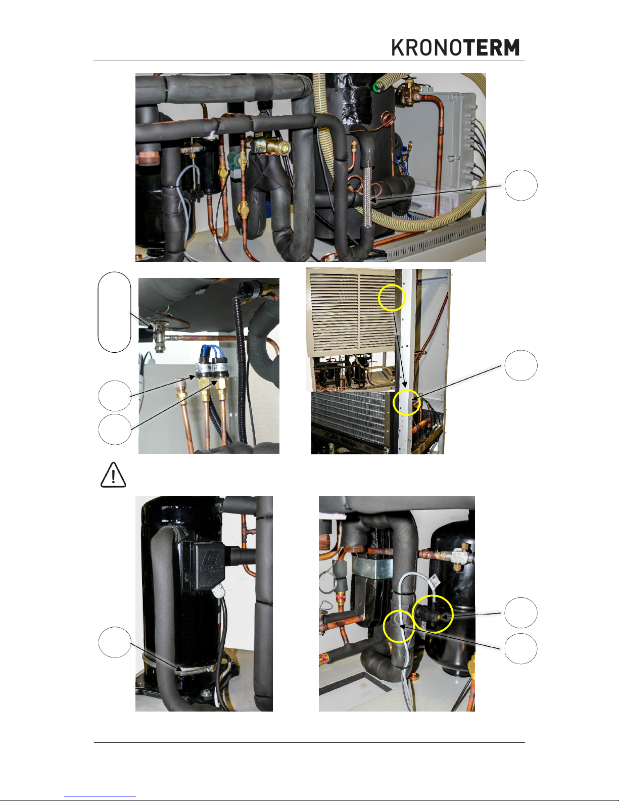
4.2017
Before replacing the pressure switch, check the declared value. Positions 15
and 24 may be replaced.
50
4.1
35
15
24
4.2
4.3
37
16
35
Page 29

©Termo-tehnika, d.o.o.
ID.: 17-17-16-4517-01
28
4.2017
WPL-16-K1
26
25
31
33
32
Page 30

©Termo-tehnika, d.o.o.
ID.: 17-17-16-4517-01
29
4.2017
WPL-18-K1
WPL-23-K1
WPL-31-K1
25
27
33
26
31
32
33
30
28
26
31
32
25
Page 31

©Termo-tehnika, d.o.o.
ID.: 17-17-16-4517-01
30
4.2017
33
30
29
26
31
32
25
38
Page 32

The headquarters of the company and place of
production
Termo-tehnika, d.o.o.
Orla vas 27a
3314 Braslovče
Tel.: (00386) 3 703 16 20 | Fax: (00386) 3 703 16 33 | Web-page:
www.kronoterm.com |
E-mail: info@kronoterm.com
 Loading...