

Page 1

ENG
Instructions for Use and Installation
Heat Pump for DHW
WP-F2–1/ E PV P
The manual has to be handed over to the end user!
Id.: 17-16-27-3033-00 / 07/2016
Page 2

© Termo-tehnika, d.o.o.
17-16-27-3033-00 1 07/2016
1 Content
1 Content ....................................................................................................................... 1
2 Warnings ..................................................................................................................... 3
3 Introduction ................................................................................................................ 5
3.1 Symbols ....................................................................................................................... 5
3.2 General ........................................................................................................................ 5
3.2.1 Obligations of the manufacturer .................................................................................... 5
3.2.2 Customer support - service .......................................................................................... 5
3.2.3 Obligations of the installer ............................................................................................ 6
3.2.4 Obligations of the user ................................................................................................. 6
3.3 Factory testing .............................................................................................................. 6
4 Safety instructions and recommendations .............................................................. 6
4.1 Safety instructions ........................................................................................................ 6
4.2 Recommendations ....................................................................................................... 7
4.3 Safety list: Coolant R-134a ........................................................................................... 7
4.3.1 Identification ................................................................................................................. 7
4.3.2 Danger mark ................................................................................................................ 7
4.3.3 Composition ................................................................................................................. 7
4.3.4 First aid ........................................................................................................................ 7
4.3.5 Fire prevention measures ............................................................................................. 8
4.3.6 In case of leakage ........................................................................................................ 8
4.3.7 Handling ....................................................................................................................... 8
4.3.8 Personal protection ...................................................................................................... 8
4.3.9 Recycling ..................................................................................................................... 8
5 Technical description................................................................................................. 9
5.1 General ........................................................................................................................ 9
5.2 Operating principle ......................................................................................................10
5.3 Technical data .............................................................................................................11
6 Installation ................................................................................................................ 11
6.1 Delivery package .........................................................................................................11
6.2 Storage .......................................................................................................................11
6.3 Transport .....................................................................................................................12
6.4 Installation location ......................................................................................................12
6.5 Installation of the device ..............................................................................................13
6.5.1 Hydraulic connection ...................................................................................................13
6.5.2 Connection for condensate drainage ...........................................................................14
6.5.3 Connecting the secondary heat source .......................................................................14
6.5.4 Electrical connection ...................................................................................................16
6.5.5 Installation of the grounding cable ...............................................................................18
7 Commissioning of the device .................................................................................. 18
7.1 Filling the device with water .........................................................................................18
7.2 Inspections before commissioning ...............................................................................19
7.3 Connecting the device to the electrical supply .............................................................19
7.4 Operation and commissioning .....................................................................................19
7.5 Controls .......................................................................................................................19
7.6 Operation programmes ...............................................................................................20
7.7 Settings .......................................................................................................................23
Page 3

© Termo-tehnika, d.o.o.
17-16-27-3033-00 2 07/2016
8 Disassembly and disposal ....................................................................................... 24
9 Care and maintenance ............................................................................................. 24
9.1 MAINTENANCE ..........................................................................................................24
9.2 Care ............................................................................................................................25
10 Disturbances in the operation ................................................................................. 25
10.1 Warnings .....................................................................................................................25
10.2 Disruptions ..................................................................................................................25
Manual for use and installation - Version 00 / Released on 7.2016
Printed in Slovenia, Copyright by Termo-tehnika, d.o.o.
This document is copyright protected. Every use beyond the law on copyright protection
without previous consent of Termo-tehnika, d.o.o. is illegal and may be penalized according
to the law. This version invalidates all previous versions. We reserve the right to change this
document and for printing errors.
Page 4
© Termo-tehnika, d.o.o.
17-16-27-3033-00 3 07/2016
2 Warnings
CAUTION
The device can be handled by children aged 8 or older and
people with reduced physical and mental capacities lacking
experience and knowledge if they are under supervision or
educated about the safe use of the device and if they
understand possible hazards.
CAUTION
Children must not play with the device.
CAUTION
Cleaning and maintenance of the device must not be performed
by children without supervision.
CAUTION
The heat pump must under no circumstance be laid in
horizontal position.
CAUTION
The heat pump must not be obstructed, objects must not be laid
up against it. Free access to the device must be provided at all
time. If during the operation of the heat pump the water
temperature exceeds 75°C, the service department has to be
notified.
CAUTION
The buffer tank for DHW is intended for storing drinking water,
this is why the water has to be in accordance with the national
regulations on drinking water in force; otherwise, damage and
a termination of the warranty can arise.
CAUTION
The device must be connected in accordance with this manual
and national regulations on electrical devices.
CAUTION
The heat pump cannot be installed on a location where air is
polluted with toxic agents which could damage the device
(stables, warehouses with dangerous substances, outdoors,
etc.).
CAUTION
The heat pump must never operate without water in the buffer
tank for DHW.
DANGER
Connecting the device to the power source can only be
performed by a qualified installer in a voltage-free state. The
Page 5

© Termo-tehnika, d.o.o.
17-16-27-3033-00 4 07/2016
cord has to be accessible and the socket must be of such type
which enables the cord to be pulled out in a simple manner.
CAUTION
The connecting cable has a standard plug suitable for a
standard socket (16 A; 230 V ac). This socket has to have its
own power supply directly from the main electrical cabinet.
Other devices must not be connected to the same line.
CAUTION
It is prohibited to move, clean or service the device while in
operation. During installation and every additional adjustments
of the device it is necessary to familiarise with the content of
the manual for use and maintenance.
CAUTION
To avoid hazards, the damaged power cable can only be
replaced by the manufacturer, his authorised installer or
another qualified person.
Page 6

© Termo-tehnika, d.o.o.
17-16-27-3033-00 5 07/2016
3 Introduction
We thank you for the trust of buying our heat pump. We are sure the device will serve well, to
your and our satisfaction. Before use, read and learn the content of the manual for safe use
and maintenance thoroughly, it will provide information about the purpose, functionality and
procedures of handling the device. The instructions are written to give you information on all
the needed activities before the first and further use.
In case the product shall be given to a third person, the manual has to be handed over to them
as well.
3.1 Symbols
Various levels of danger can occur while performing installation, maintenance and use. Certain
parts of this manual contain warning information with which we wish to provide safety for the
user, eliminate possible hazards and ensure correct use of the device.
This symbol marks sections which symbolise various risks for the user or the
device.
DANGER: Risk of situations which can lead to serious physical injuries.
WARNING: Risk of situations which can lead to minor physical injuries.
CAUTION: Risk of injury or damage to the device
NOTE
This symbol marks sections which symbolise important information for the user.
3.2 General
3.2.1 Obligations of the manufacturer
Our products are in accordance with current European directives and standards. Products are
marked with the mark CE and they have all the needed documentation.
For customer interests, improvements of quality and device safety are constantly being
implemented, this is why all specifications listed in this document can be changed without prior
notification.
As manufacturer, we cannot take responsibility in the following cases:
Non-compliance with the manual for the device.
Incorrect and/or inadequate maintenance of the device.
Non-compliance with the manual for the installation of the device.
3.2.2 Customer support - service
Termo-tehnika d.o.o. provides customer support and service during the warranty period.
When placing a service order, please provide the following information:
Product
Exact name of the product
Serial number
Year of manufacture
All needed information can be found on the label printed on the device.
Page 7

© Termo-tehnika, d.o.o.
17-16-27-3033-00 6 07/2016
NOTE
In case of any change or replacement of original parts, forced or incorrect use
of the device, the warranty is terminated. Eventual costs arising from the
service procedure are fully covered by the user.
During the warranty period service and maintenance can only be performed by
Termo-tehnika d.o.o. or a service provider authorised by Termo-tehnika d.o.o.
Otherwise, the warranty is terminated.
3.2.3 Obligations of the installer
The installer is responsible for installing and commissioning the device in accordance with
the following requirements:
To thoroughly study the instructions for use and installation accompanying the device
before installation.
To install the device in accordance with the instructions and national legislation, policies
and standards in force.
To perform the first commission and eliminates all eventual irregularities found at the
commission.
To instruct the user about the operation of the whole system.
To alert the user to regularly maintain the device for keeping the device functioning
properly throughout its entire lifespan.
To give the user all the documentation accompanying the device.
3.2.4 Obligations of the user
To ensure unobstructed and effective operation of the device, the user must consider the
following instructions:
To thoroughly study the instructions for use and installation accompanying the device
before installation.
Installation and commissioning of the device have to be performed by a qualified and
authorised person.
To allow the authorised contractor for commissioning or ask him to thoroughly explain
the functioning and operation of the device.
To ensure regular yearly inspections and maintenance of the device by the authorised
maintenance worker.
These instructions for installation and use must be kept in a suitable dry place close to
the device.
3.3 Factory testing
To ensure high quality standard, each heat pump is tested before exiting the factory in the
following points:
Tightness of the cooling cycle
Water-tightness
Air-tightness
Electrical safety
Functionality
4 Safety instructions and recommendations
4.1 Safety instructions
The device is manufactured in accordance with directives and standards of the joint European
market (CE). As warning against possible hazards during the operation of the heat pump,
follow the safety instructions while handling the device.
Page 8
© Termo-tehnika, d.o.o.
17-16-27-3033-00 7 07/2016
4.2 Recommendations
CAUTION
It is prohibited to move, clean or service the device while in operation. During
installation and every additional adjustments of the device it is necessary to
familiarise with the content of the manual for use and maintenance.
DANGER
Connecting the device to the power source can only be performed by a qualified
installer in a voltage-free state. The cord has to be accessible and the socket
must be of such type which enables the cord to be pulled out in a simple manner.
CAUTION
The heat pump must not be obstructed, objects must not be laid up against it.
Free access to the device must be provided at all time. If during the operation of
the heat pump the water temperature exceeds 75°C, the service department has
to be notified.
4.3 Safety list: Coolant R-134a
4.3.1 Identification
The operating agent of the device is the hydrofluorocarbon HFC 134a. The coolant is not toxic,
flammable or explosive, it is not harmful to the ozone, but it is heavier than air which can cause
the extrusion of air from the room. The consequence could be a lower concentration of oxygen
in the air; but because of the very low quantity of the coolant in the device, there is no real
hazard for health. A lower concentration of oxygen can only occur in rooms smaller than 10 m3
which are not ventilated and are underground where the coolant, which is heavier than air, can
remain for a longer period of time. Despite this, we recommend reading the safety list of the
coolant manufacturer and follow its instructions.
4.3.2 Danger mark
DANGER
Risk of situations which can lead to serious physical injuries.
1. Risk of endangering health:
The coolant fumes are heavier than air. The coolant can displace the air in the room
and the lack of oxygen can cause dizziness, loss of consciousness or even suffocation.
Liquefied gas: Contact with the liquid can cause serious frostbite and damage to the
eyes.
2. Product classification: This coolant is not characterised as a product “dangerous to
health/harmful” in accordance with the EU regulations.
4.3.3 Composition
1. Chemical composition: R – 134a C2H2F4 – Tetrafluoroethane
Name of ingredient Concentration CAS
number
CE number GWP
1, 1, 1, 2 – Tetrafluoroethane R-134a 100% 811-97-2 212-377-0 1300
4.3.4 First aid
1. In case of inhalation: Remove the person from the contaminated room and bring them
outside. If the person does not feel well, take them to the doctor.
2. In case of contact with skin: Frostbite is treated the same as burns. Thoroughly rinse
with clean water and do not remove clothing (danger of adhesion of clothing with the
skin). If skin burns occur, call the doctor immediately.
Page 9

© Termo-tehnika, d.o.o.
17-16-27-3033-00 8 07/2016
3. In case of contact with the eyes: Immediately rinse with water and keep the eyelids
open during this time (at least 15 minutes).
4. Consult an eye doctor.
4.3.5 Fire prevention measures
1. Suitable fire extinguishing agents: The use of fore extinguishing agents is limited by the
room and circumstances in which the extinguishing takes place. The coolant does not
limit the use of any fire extinguishing agent
2. Special dangers:
Raising of pressure. In the presence of air (oxygen) at certain temperatures and
pressures, flammable substances can form.
At high temperatures (above 200°C), toxic and corrosive gasses can start
evaporating.
3. Special intervention methods: cool the part of the device or coolant subject to heat with
a fire extinguisher.
4. Protection for fire-fighters:
A fully closed mask with oxygen tube.
Full-body protection.
4.3.6 In case of leakage
1. Special safety precautions:
Avoid contact with skin and eyes - danger of frostbite.
Do not intervene without proper protective gear.
Do not inhale the fumes - danger of suffocation because of inadequate concentration
of oxygen in the air.
Evacuate the dangerous area.
Stop the leakage.
Remove all possible sources of ignition and heat.
Thoroughly vent the room where the coolant leakage occurred (danger of suffocation).
Avoid contact with skin and eyes
2. Cleaning / decontamination: Let the coolant evaporate.
4.3.7 Handling
1. Technical measures: Venting is necessary in case of leakage.
2. Safety precautions:
Smoking prohibited.
Prevent the build-up of electrostatic charge.
Maintenance and service works must be carried out only in a well vented room.
4.3.8 Personal protection
1. Respiratory system protection:
In case of insufficient venting: safety mask of AX type
In closed spaces: a fully closed mask with oxygen tube.
2. Hand protection: protective gloves made of nitrile rubber or leather.
3. Eye protection: protective glasses with side guards.
4. Skin protection: clothing mostly made of cotton.
5. Industrial hygiene: it is not allowed to drink, eat or smoke at the workplace.
4.3.9 Recycling
1. Product waste: Consult with the manufacturer in connection with recycling or
processing.
2. Dirty packaging: reuse or recycling after decontamination. Dispose of in designated
institutions.
Page 10

© Termo-tehnika, d.o.o.
17-16-27-3033-00 9 07/2016
NOTE
Removing the coolant must be performed in accordance with directive ES
842/2006 and other national and local regulations.
5 Technical description
5.1 General
This device is a heat pump for heating DHW in residential or small business premises where
the daily use of hot water does not exceed 700 litres. When heating DHW, the heat pump also
cools the room where it is located. Thus the heat pump can be used for heating DHW as well
as for cooling rooms; here we must point out that the heat pump will cool the room only if there
is a need for heating DHW. If there is no need, the heat pump will not cool the room.
NOTE
For maximal efficiency and economical use, we advise to use air from rooms
where waste heat is generated (DHW rooms, laundries, kitchens, basements,
pantries ...) and that the air temperature is as high as possible.
Dimensions:
Picture 1: Heat pump dimensions
Mark
Dimension
B
480
H
780
T
290
T1
420
1 Compressor 9 Electrical boiler
2 Condenser 10 Mg. Anode
3 Dehydrator 11 Safety thermostat sensor
4 Expansion valve 12 High-pressure switch
5 Evaporator 13 DHW sensor
6 Fan 14 Solar heat exchanger
7 Magnet valve 15 DHW heat exchanger
8 Expansion valve sensor 16 Buffer tank for DHW
Page 11

© Termo-tehnika, d.o.o.
17-16-27-3033-00 10 07/2016
5.2 Operating principle
The cooling system of the heat pump is a closed circuit system where the coolant R134a
circulates as heat exchanger. At lower pressure and temperature (i.e. 10°C) the coolant is
evaporated in the evaporator of the heat pump and thus removes heat from the air. Afterwards,
the compressor compresses the coolant to a higher pressure, this results in the raising of the
coolant temperature to a level higher than the water temperature in the DHW. The coolant then
releases the heat in the condenser into the water and condenses as a result. With the
expansion of the coolant the pressure and temperature in the coolant fall to their initial level,
completing the circular process. This process is repeated throughout the heat pump’s
operation.
Buffer tank for DHW
Additional heat pump WPF2-1 is a generator of the heat pump intended to be installed to the
water buffer tank with a side flange φ180mm/8.
Additional electrical heater
The additional electrical heater EH with 1.2 kW functions as:
safeguard against vaporizer freezing. In case the air temperature in the room is too
low for the heat pump’s operation, the EH turns on automatically;
it is the reserve source in case of a malfunction of the heat pump generator.
Anti-freeze sensor
The regulator of the heat pump senses the air temperature flowing through the evaporator. In
case the air temperature is lower than 7°C (factory setting), it performs a safety shut-down of
the device for at least 30 minutes. In this case heat pumps with electrical heaters automatically
switch to heating with the electrical heater, devices with a DHW switch to heating with DHW
(turning on the circulation pump).
The operation and safety thermostat of the electrical heater
The electrical heater has its own operation and safety thermostat which is limited to 85°C.
CAUTION
When the electrical heater is in operation, it heats water to approx. 65°C.
Because it only heats the upper part of the DHW, the temperature regulator does
not show correct values because its sensor is placed at the bottom part of the
DHW and usually senses the colder part of the water. When heating with DHW
or solar collectors, water can be heated above 85°C which triggers a shut-down
of the safety thermostat of the electric heater. In this case the electrical heater
has to be manually reset. To reset the electrical heater, call an authorised
maintenance worker.
Page 12

© Termo-tehnika, d.o.o.
17-16-27-3033-00 11 07/2016
Controlling water temperature in the DHW
The OPTITRONIC regulator is used to control and heat water to the desired temperature.
It switches on or turns off the compressor and fan according to the desired temperature of
water. In case of low air temperature, it switches on the circulation pump of the DHW. The
maximal temperature setting for heating is 55°C and 60°C during overheating.
The minimal water temperature is 7°C.
High-pressure protection for the cooling system
To prevent high pressure in the cooling system and associated damage the device has a builtin high-pressure safety switch which turns off the device in case of high pressure. In this case,
the error E7 is displayed on the screen.
Operating conditions
The temperature of the surroundings in normal operation must be between 8°C and +35°C.
The air must be clean, the relative moisture at +40°C must not exceed 50%. At lower air
temperatures the relative moisture can be higher. With devices installed at high altitudes, lower
air pressure can cause degraded performance of the device.
CAUTION
The heat pump cannot be installed on a location where air is polluted with toxic
agents which could damage the device (stables, warehouses with dangerous
substances, outdoors, etc.).
5.3 Technical data
Model
WP-F2-1
Max. heating power:
1830 W (3030 W)*
El. power:
480 W (1680 W)*
Max. el. power:
550 W (60°C) (1750 W)*
El. Power supply:
230 V a.c.
El. Heater
1200 W
Max. el. Power of circulation pump
300 W
Coolant / quantity:
R134a / 450 g
Max. temp.:
55°C (60°C)
Needed air flow
500 m3/h
Protection
class
IPX1
Range of operation
between 8°C and +35°C
Electrical safeguard:
C 16 A, (230 V a.c.)
Sound power
52 dB(A)
Maximal pressure of cool. system
2,3 Mpa (23 bar)
* In case the el. heater is in operation
6 Installation
6.1 Delivery package
Delivery package:
1. Heat pump
2. Instructions for Use and Installation
3. Lid screws
6.2 Storage
The device has to be stored in a dry and clean place. The allowed storing temperature is
between 10 °C and 45°C, for a short period (up to 24h) also up to 55°C.
Page 13

© Termo-tehnika, d.o.o.
17-16-27-3033-00 12 07/2016
6.3 Transport
Before transport, the heat pump must be protected with protective foil or cardboard packaging
to avoid damage such as indentations and bruising. If needed, it can also be additionally
protected from mechanical damage. After placing the device into final position, the device must
stand still for a minimum of 2 hours before start-up in order for the oil to flow back into the
compressor.
The upper part of the device with the generator protected by a plastic lid does not bear larger
loads. This is why it must not be used as a bearing or supporting point during transport.
CAUTION
While moving the device, it has to be disconnected from the power supply.
WARNING
The mass of the device is too great for manual transfer. This could lead to
injuries and damage of the device. All responsibility for eventual injuries or
damage to property or the device is taken by the user.
Devices for transporting goods must be used.
CAUTION
The heat pump must under no circumstance be laid in horizontal position.
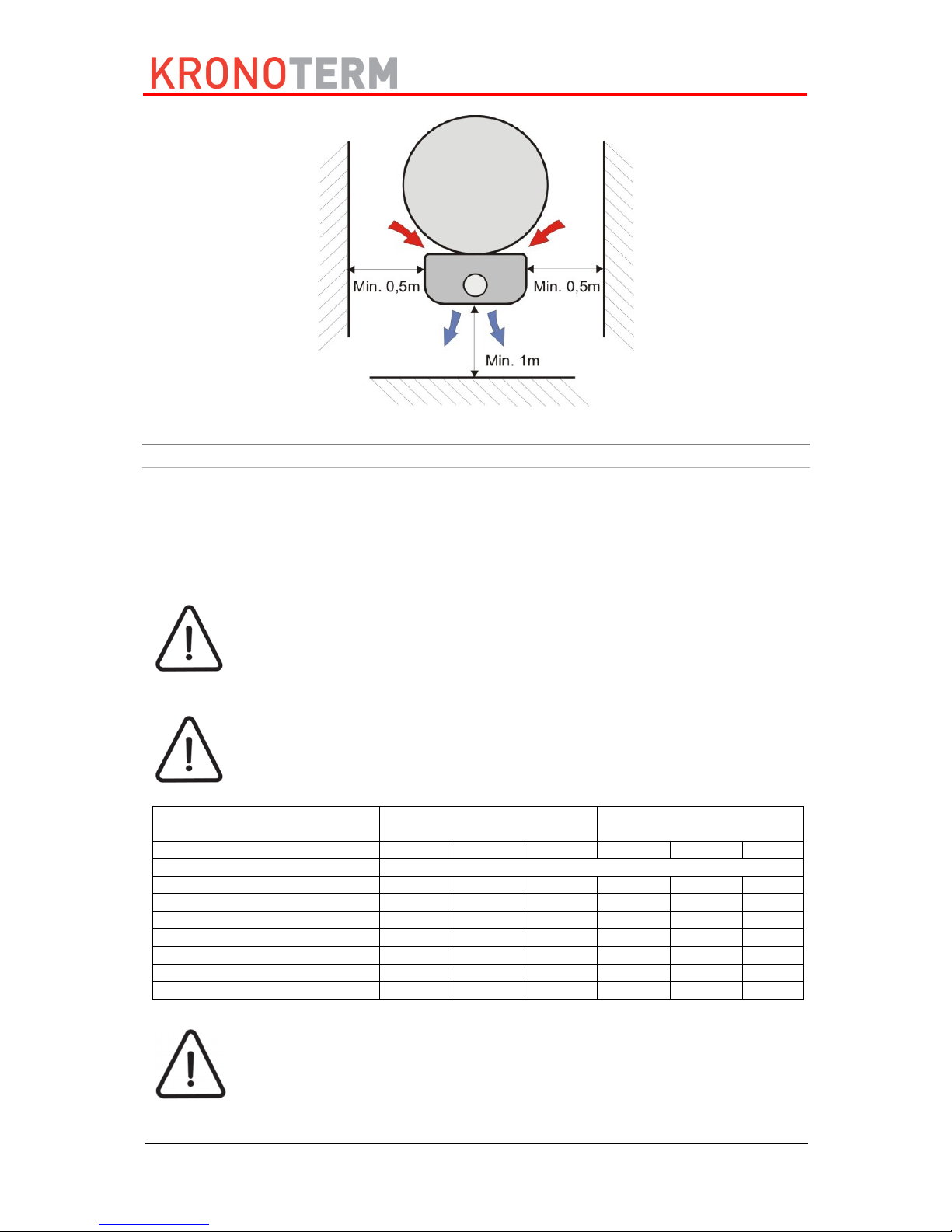
6.4 Installation location
The heat pump can be installed in rooms which can be cooled (DHW room, pantry, basement
...). It must not be installed in rooms where there are harmful substances in the air (stables,
warehouses with dangerous substances, the outdoors ...). The minimal room space is 20 m3.
The heat pump is designed to take the heat from the surrounding air or suck the air through
air channels and blow it into the adjoining rooms or surroundings.
Picture 2: Heat pump placement
Page 14
© Termo-tehnika, d.o.o.
17-16-27-3033-00 13 07/2016
Picture 3: Minimal clearances
6.5 Installation of the device
6.5.1 Hydraulic connection
The hydraulic connection has to be installed in accordance with the national and local
regulations for connecting buffer tanks for DHW in force. The maximal pressure in the buffer
tank for DHW must not exceed 6 bar. In case the pipe heat exchanger in the buffer tank for
DHW will not be used, it must be filled with anti-freeze liquid to prevent corrosion in the heat
exchanger. The filled conductor must not be closed tightly on both sides (equalisation of
pressure because of temperature differences).
Installing an expansion tank of appropriate volume is mandatory.
CAUTION
Because different materials are used on the pipe installation, all connections on
the heat pump (cold and hot water, circulation, heat conductor) have to be
galvanically isolated; otherwise corrosion can occur on the inner side of the
buffer tank. We recommend placing galvanic isolators made of red brass the
length of at least twice the diameter of the pipe on the connections.
CAUTION
The buffer tank for DHW is intended for storing drinking water, this is why the
water has to be in accordance with the national regulations on drinking water in
force; otherwise, damage and a termination of the warranty can arise.
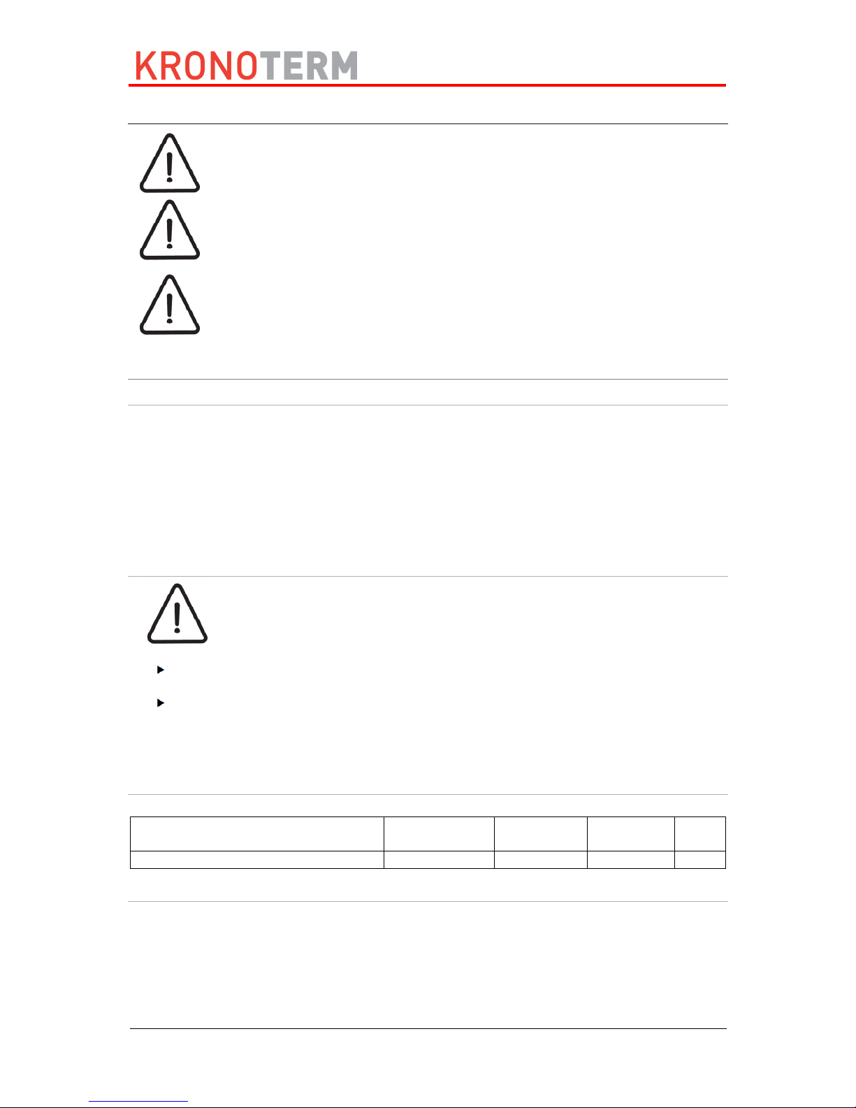
Dimensions of the expansion tank:
Pressure setting of the safety
valve [bar]
6 10
Precharge [bar] 3.0 3.5 4.0 3.0 3.5 4.0
Volume of the DHW [L] Volume of the appropriate expansion vessel [L]
200 10 13 17 6 6 7
250 12 16 22 8 8 9
300 15 19 26 9 10 10
400 19 25 35 12 13 14
500 24 32 44 15 16 17
800 39 50 70 24 25 28
1000 48 63 87 30 32 34
*This is only a recommendation. * The actual size of the expansion tank has to be defined by the installer/design
engineer according to the extent of the system the device will be installed in.
CAUTION
For normal operation of the expansion tank, it is necessary to perform proper
adjustments of the tank’s working pressure according to the pressure in the water
supply network. The settings have to be checked every 6 months.
Page 15

© Termo-tehnika, d.o.o.
17-16-27-3033-00 14 07/2016
6.5.2 Connection for condensate drainage
By removing heat from the air, condensate from air moisture forms on the heat pump. The
formation of condensate from air moisture depends on the temperature and relative moisture
of air. In some cases no water is extracted from the air, in other cases more than 10 litres of
water condensate can be extracted. The condensate accumulating in the condensate vessel
must be routed into the drain or external vessel via condensation pipe (φ16mm PVC pipe). This
has to have a minimal capacity for 10 L of water.
Caution: When installing the condensate drain, make sure the pipe is always sloped
downwards, a syphon must be installed at the outflow with a water column of at least 5 cm.
This prevents the intake of unpleasant odours from the drains.
CAUTION
A constant unobstructed flow through the condensation pipe must be
ensured, this is why it has to be made sure from time to time the pipe is not
blocked or bent.
Picture 4: Installation of the condensate pipe
CAUTION
The condensate pipe must not be higher in any place than the condensate
vessel; this is why it must be installed as seen on
Picture 4.
CAUTION
The condensate pipe must not be routed into the washing machine syphon; the
overpressure could stop the condensate from the condensate vessel from
draining through the pipe and would start dripping on the housing of the heat
pump.
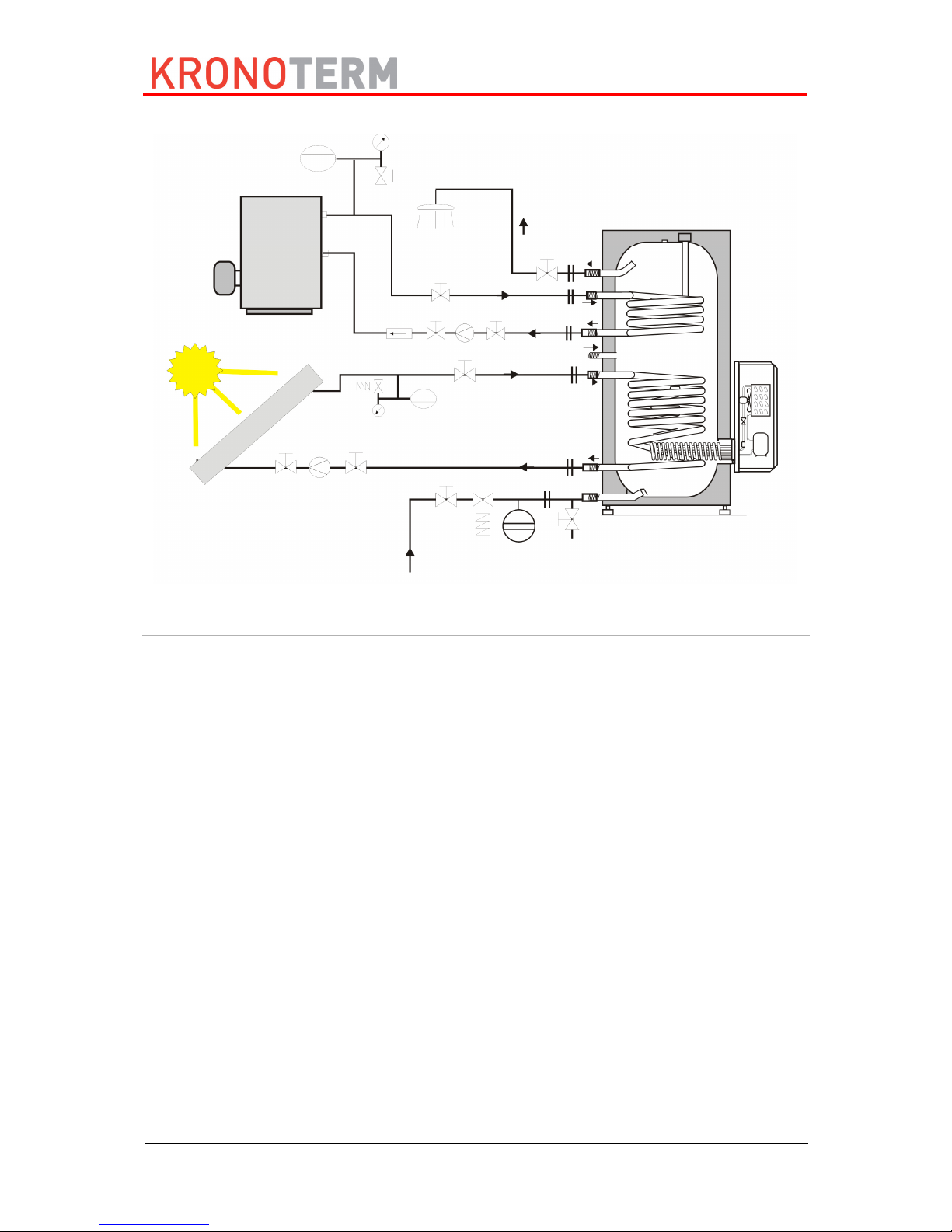
6.5.3 Connecting the secondary heat source
The DHW in the buffer tank can be heated with various heat generators. The primary generator
is a heat pump; a DHW or solar collectors can be installed on the heat pump for situations
when the heat pump cannot operate or as the reserve heat generator - (this mode of operation
is called bivalent). There are some circuit diagrams below.
CAUTION
Because different materials are used on the pipe installation, all connections on
the heat pump (cold and hot water, circulation, heat conductor) have to be
galvanically isolated; otherwise corrosion can occur on the inner side of the
buffer tank. We recommend placing galvanic isolators made of red brass the
length of at least twice the diameter of the pipe on the connections.
WP-F2-1
A [mm]
50
B [mm]
225
C [mm]
273
D [mm]
220
E [mm]
420
A
Page 16

© Termo-tehnika, d.o.o.
17-16-27-3033-00 15 07/2016
CAUTION
- Water in the heating system must be in accordance with VDI 2035. The water
must be soft, anti-corrosion and anti-bacterial agents must also be used to
prevent corrosion.
- Before filling the system, it has to be cleaned of all impurities.
- The heating system must be thoroughly vented. Air, including diffusion air must
be prevented entering the device.
Picture 5: HP in combination with solar collectors
Picture 6: HP in combination with the DHW
Page 17
© Termo-tehnika, d.o.o.
17-16-27-3033-00 16 07/2016
Picture 7: HP in combination with DHW and solar collectors
6.5.4 Electrical connection
After connecting the heat pump to the water supply and it is thoroughly vented it can be
connected to the power supply.
1 Compressor 9 Connecting the circulation pump
2 Fan 10 Compressor condenser
3 Screen 12 El. heater
4 Pressure switch 13 Safety thermostat
5 NTC probe - water 16 PV signal connection
6 NTC probe - air 17 Relay board
7 Supply cable 18 Keyboard
8 Grounding 19 Filter
Page 18

© Termo-tehnika, d.o.o.
17-16-27-3033-00 17 07/2016
Picture 8: El. scheme
CAUTION
The connecting cable has a standard plug suitable for a standard socket (16 A;
230 V ac). This socket has to have its own power supply directly from the main
electrical cabinet. Other devices must not be connected to the same line.
CAUTION
Connecting the heat pump must be performed by an electrician!
Page 19

© Termo-tehnika, d.o.o.
17-16-27-3033-00 18 07/2016
6.5.5 Installation of the grounding cable
Picture 9: Installation of the grounding cable
A Heat pump flange E M12x40 screw
B Housing F Seal
C Heat buffer tank flange G Grounding cable
D Toothed washer
Grounding of the DHW must be performed via the grounding screw as shown on Picture 9.
The needed components are pre-assembled and included.
The grounding is performed by the following procedure:
1. The grounding of the DHW is performed by Picture 9.
2. Check the protective wire.
3. The protective wire is checked with the resistance gauge. The resistance between the
grounding connection and the inside of the casing must be between 600 and 700Ω.
This ensures the installation was performed correctly. If the given value is not achieved,
check whether the grounding cable is installed correctly.
7 Commissioning of the device
7.1 Filling the device with water
After an expert has connected the HP to the water supply, the system has to be filled with
water and thoroughly vented. This is performed by opening all taps in the residence. When
water flows uninterruptedly from all taps, the system is thoroughly vented.
CAUTION
The heat pump must never operate without water in the buffer tank for DHW.
Otherwise, damage to the device may occur.
Page 20

© Termo-tehnika, d.o.o.
17-16-27-3033-00 19 07/2016
7.2 Inspections before commissioning
Before commissioning, the following inspections must be performed on the device:
The buffer tank for DHW must be filled with water and thoroughly vented.
All hydraulic connections must be tightly sealed.
Appropriate setting of the expansion tank.
All safety elements must work.
7.3 Connecting the device to the electrical supply
The device is equipped with a standard connection cable. Before commissioning, the plug of
the connection cable has to be plugged into the standard socket 16 A, 230 V a.c.
After connecting the device to the power supply, the device starts a commissioning sequence
which consists of a sequential display of all device settings. In case the commissioning
sequence does not display, the service provider has to be contacted.
7.4 Operation and commissioning
After the HP has been correctly connected to the electrical network according to these
instructions, the display shows the regulator version and the factory set programme of
operation (i.e. P.1) and all operating parameters and their values after 2 seconds. 30 seconds
after connecting the device to the mains, the entire system starts up and starts heating the
water in the DHW. The heat pump starts operating and operates until the set breaking
temperature is reached. The breaking temperature is factory set to 52°C. After shut-down the
operation is interrupted until the water cools for 5 °C, i.e. to 47 °C. When the water in the buffer
tank reaches this temperature, the heat pump turns on again. The user can freely raise the set
breaking temperature but no more than 60°C (restriction of the regulator) or freely lower it.
Overheating the water to 60°C is factory restricted to this value and cannot be readjusted.
The air temperature in the room the switch to the reserve heat source is performed is factory
set to 7°C. This temperature can be freely changed by the user (instructions below).
7.5 Controls
Picture 10: Control unit
Indicator
Description
Page 21

© Termo-tehnika, d.o.o.
17-16-27-3033-00 20 07/2016
7.6 Operation programmes
Indicator
status
Operation
programme
DESCRIPTION
☼ Is not
illuminated
Is not
illuminated
P.0
Operation of the heat pump is turned off, only the DHW water
temperature display is in operation.
☼ Is
illuminated
Is not
illuminated
P.1
The device in this mode heats the water with the compressor to
the set temperature. It operates inside the limited temp. zone of
the intake air. In case of low temp. of intake air the device performs
a safety shut down of the compressor
☼ Is not
illuminated
Is
illuminated
P.2
The device in this mode heats the water with the DHW to the set
temperature.
Note: the air in the room does not affect the operation.
☼ Is not
illuminated
Is
blinking
P.3
The device in this mode heats the water with the electric heater
to the set temperature.
Note: the air in the room does not affect the operation.
☼ Is
illuminated
Is
illuminated
P.4
The device in the automatic mode heats the water with the
compressor to the set temperature. It operates inside the limited
temp. zone of the intake air. In case the temp. of intake air is too
low or lower than the set minimal operating temperature L1, the
device automatically switches to heating water with DHW.
☼ Is
illuminated
Is
blinking
P.5
The device in the automatic mode heats the water with the
compressor to the set temperature. It operates inside the limited
temp. zone of the intake air. In case the temp. of intake air is too
low or lower than the set minimal operating temperature L1, the
device automatically switches to heating with electric heater.
Specifics
In case of switching to the reserve heating source
☼ Is
blinking
Is
blinking or
illuminated
P.4
The temperature of intake air is too low or lower than the minimal
set temperature L1, this is why the heating in automatic
programme P4 is performed by the DHW; in automatic
programme P5 it is performed by the electric heater. During this
time the compressor is in safety shut-down.
1
Indicators of operation mode
2
Temperature and parameter display
3
Quick key “P” for changing the operation mode
4
Quick key “HT” for thermal disinfection (protection against legionella) and quick
heating
5
“HT” thermal disinfection operation or quick heating indicator
6
Quick key “ - ” for setting temperature
7
Quick key “ + ” for setting temperature
8
Compressor safeguard indicator (PV signal indicator in combination with 9)
9
Active PV signal indicator
Page 22

© Termo-tehnika, d.o.o.
17-16-27-3033-00 21 07/2016
☼ Is
illuminated
Is
blinking
P.6
The device in the automatic mode heats the water with the
compressor to the set temperature. It operates inside the limited
temp. zone of the intake air. In case the temp. of intake air is too
low or lower than the set minimal operating temperature L1, the
device automatically switches to heating with electric heater. In
case of the presence of a PV signal, the desired value increases
by L6.
NOTE
Pressing the key for the first time checks the currently chosen operating
programme (it can also be read from the operating indicators themselves -
see table above). Pressing the key in the time frame of 8 seconds
switches between different programmes available.
Choosing the mode (source) also determines the heat source performing
the overheating of water.
List of parameters
Parameter
Parameter description
Range of settings
Default value
Programme P0 ÷ P6
[P5]
Desired
temp.
30 ÷ H9
[52]
L0 Temp. of intake air in °C -15 ÷ 95
L1 Min. operation temp. in °C 5 °C ÷ 30°C
[7]
L2 Time interval of overheating in days 1 ÷ 99 days
[14]
L3 Display of active outputs (only
display)
0 ÷ 7 0 – no output is
active
1 – KO
2 – CP
3 – HP + CP
4 – EH
5 – HP + EH
6 – CP + EH
7 – HP + CP + EH
L4 Shut-down temperature (hysteresis) 1 ÷ 20 °C
[10]
L5 switching on the auxiliary heat
source; quick heating
--,1 ÷ 55 °C
[--]
L6 Raising the temperature at PV 1 ÷ 20 [5]
L7 Standby at PV signal 1 ÷ 10 [3]
Operation programmes
1. Heating water with heat pump (programme P.1 must be chosen): The water is heated
with the heat pump until the set temperature is reached and until the intake air temperature
is above the min. temperature of operation - 5°C. If the air in the room cools below the set
operating temperature, the device performs a security shut-down of the device’s
compressor. When the air temperature in the room is above the minimal temperature at
least for 30 minutes, the device activates the device’s compressor and continues heating
the water up to the set temperature. Water overheating in the programme P.1 is performed
with the device’s compressor.
2. Heating the water with DHW or solar collectors (programme P.2 must be chosen):
the circulation pump must be properly connected to the external connecting cabinet of the
heat pump: the circulation pump of the DHW is turned on until the set water temperature
is reached. The condition for successful heating is that the DHW is turned on and heated!
Page 23

© Termo-tehnika, d.o.o.
17-16-27-3033-00 22 07/2016
NOTE
Water overheating in the programme P.2 is performed by the DHW or solar
collectors. Air temperature does not influence the operation.
3. Heating water with the electric heater (programme P.3): the electric heater (EH) is
turned on until the set water temperature is reached. Air temperature does not influence
the operation.
NOTE
Water overheating in the programme P.3 is performed with the electric
heater. Air temperature does not influence the operation.
4. Heating water with the compressor and automatic switch to the reserve source when
the intake air is too cold (programmes P.4 and P.5 must be chosen): the heat pump
operates completely independently with a priority of heat pump operation until the set water
temperature is reached and the temperature of intake air is above the switching
temperature (L.1). If the intake air falls under the temperature set for the switch, the device
automatically switches to heating with reserve source (in programme P.4 to the DHW /
solar collectors and in programme P.5 to the electric heater).
NOTE
The switch of operation from the reserve source back to heating the water
with the heat pump occurs after 30 minutes when the intake air warms up for
3°C above the switching temperature (L.1).
NOTE
Water overheating in programme P.4 or P.5 is performed with the currently
active heat generator.
5. Heating water with the heat pump in combination with photovoltaic panels
(programme P.6); in this operating mode the device operates as in programme P.4 with
the difference that if there is an active signal from the inverter of photovoltaic power plant,
the heat pump raises the water temperature in the DHW for the value set in the parameter
L.6.
NOTE
During the active PV signal the indicator of the PV signal and the indicator of
the compressor safeguard are illuminated. When the compressor turns off
and the PV signal is still active, the indicator of the compressor safeguard
starts flashing.
6. Thermal disinfection / anti-legionella programme
One-time heating of water above 60°C is turned on with the key (the indicator on the key
flashes). After the overheating finishes, the indicator on the key turns off. We can end the
overheating early by pressing the key again. The National Institute of Public Health advises
water overheating once every fourteen days.
NOTE
The indicator HT is illuminated during the thermal disinfection.
Page 24

© Termo-tehnika, d.o.o.
17-16-27-3033-00 23 07/2016
IMPORTANT
In case the overheating is not successful in 12 hours, the function turns of
and continues with normal heating.
7. “Quick heating” of water
One-time quick heating of water is turned on by holding the key for approx. 20 seconds
(the indicator on the key flashes). After reaching the desired water temperature the indicator
turns off. We can end the quick overheating early by pressing the key again.
NOTE
During the operation of quick heating the HT indicator blinks.
IMPORTANT
In case the heating is not successful in 12 hours, the function turns of and
continues with normal heating.
7.7 Settings
1. Setting the water temperature: pressing the key or for the first time displays the
currently set temperature, additionally pressing the key or (in the time frame of 8s)
triggers its modification. If we wait for 5s, the new setting will be stored after the blinking stops.
2. Switching between various operation programmes: switching between various operation
programmes is performed by pressing the key The chosen operating mode is indicated by
the illuminated indicator for operation and the reading when the key is pressed for the first
time (see table above). Pressing the key in the time frame of 8 seconds switches between
available operating programmes.
3. Display and settings of parameters
You can enter the menu displaying the parameters by shortly pressing keys and at the
same time, we can move between the displays themselves with the key or .
When the desired parameter has been chosen, we have to wait for 8s, then the value of the
chosen parameter is displayed for 8s. After 8s the display returns into its basic menu which
displays the current water temp. in the DHW.
4. Setting the temperature of the switch to the reserve heat source (only the automatic
programme P.4): we enter the menu displaying the parameters by shortly pressing keys
and at the same time, we switch between displays with the key or . (see chapter
for parameter display). Choose the parameter L.1, after a few seconds the set temperature
of the switch is displayed (factory set to +7°C). We can change the set temp. during its display
with keys and (from +5°C to +25°C).
After setting the desired value, wait for 8s; after the blinking stops, the setting is saved. The
safety time delay disables a restart of the compressor after the temperature drop under the
switching value (7°C) for 30 minutes.
5. Setting the time interval of automatic thermal disinfection: you can enter the parameter
display menu by shortly pressing keys and at once; you can switch between displays
with the key or (see chapter for parameter display). Choose the parameter L.2, after a
couple of seconds the set interval of overheating is displayed (factory set to 14 days). During
the display of the set value no. of days, it can be modified with the key or (from 7 to
Page 25

© Termo-tehnika, d.o.o.
17-16-27-3033-00 24 07/2016
99 days). After setting the desired value, wait for 5s; after the blinking stops, the setting is
saved. The National Institute of Public Health advises water overheating once every fourteen
days. Too frequent overheating is not advised because the energy consumption with
overheating is 1/3 higher than normal operation of the heat pump.
8 Disassembly and disposal
The device as a whole has a lifetime of at least 8 years if the instructions for safe use and
maintenance are considered. Individual components have different lifetimes, this is why they
have to be promptly replaced with new parts in cases of possible malfunctions, wear and
mechanical damage.
Replacement can be performed only by using technically adequate or original replacement
parts.
After its lifespan has ended, the whole device must be disposed of in accordance with current
regulations for waste management.
9 Care and maintenance
The following maintenance work is recommended for a reliable and efficient operation of the
device.
CAUTION
The device must be connected in accordance with this manual and national
regulations.
9.1 MAINTENANCE
Recommended regular controls:
Control of the safety valve on the water supply installation.
Visual control of the HP evaporator. If the evaporator is very dusty, the device must be
disconnected from the power supply. Remove the plastic housing of the device and
clean the evaporator. The use of a vacuum cleaner or compressed air is recommended.
Be careful not to damage the lamellas of the evaporator or any other component.
Clean the evaporator as needed.
WARNING
The lamellas of the evaporator are very sharp. Injuries can occur if cleaning is
not done carefully.
WARNING
The evaporator must not be cleaned with a water jet or rinsed with water. Danger
of damaging the device.
Before contacting the service, check the following:
Whether the installation leading to the heat pump is laid directly from the main electrical
cabinet.
Whether only this device is connected to the power cable from the main electrical
cabinet.
Whether the connecting cable is damaged.
Check whether the air flow is unobstructed (dirt, grates, etc.).
Check whether the intake air temperature is above the lowest temperature at which the
HP still operates (see page 11).
The service must check the Mg. anode in the DHW buffer tank every two years. It is
recommended to also clean the heat pump at this time.
Page 26

© Termo-tehnika, d.o.o.
17-16-27-3033-00 25 07/2016
9.2 Care
CAUTION
The surface of the heat pump can be damaged! The surface of the heat pump
can get damaged by using inappropriate cleaning agents. Do not use cleaning
agents which could damage plastic. The use of solvents and chlorinated
cleaning agents is prohibited. Use a wet towel and soap if necessary.
Clean the device with a non-abrasive wet towel and a mild soapy solution.
Do not use aggressive cleaning agents, solvents or chlorinated cleaning agents.
10 Disturbances in the operation
10.1 Warnings
WARNINGS
CAUSE
SOLUTION
A1
Shut-down of HP
because of low
intake air
temperature.
The room must be vented to raise the air temperature above the lower limit.
Set the shut-down temperature to a lower value.
CAUTION: FREEZING OF
THE EVAPORATOR CAN OCCUR WITH SHUT-DOWN TEMPERATURES
LOWER THAN -10 °C. LOWER VALUES CAN BE USED ONLY IN CASE
OF VERY LOW RELATIVE MOISTURE (UNDER 35°C).
If the HP is connected to a DHW, the programme must be set to P2 or P4.
The programme P2 will only heat water with the DHW, programme P4 will
heat the water with the HP (when the environmental conditions are suitable)
and DHW.
A3
Shut-down of HP
because of high
intake air
temperature
(40°C)
The room must be vented to lower the air temperature below the upper limit.
If the temperature of the intake air is constantly above the upper limit, another
room must be found for setting up the HP or the air ducts have to be routed
into the room with a temperature lower than the upper level (40°C).
10.2 Disruptions
ERRORS CAUSE SOLUTION
E7
High pressure in the
cooling system.
Check whether the buffer tank has enough water.
You can erase the error by pressing the + key. If the error
persists, contact the service.
Alternately
E8
and
¯ ¯
The sensor for DHW is
not connected.
Check whether the sensor is connected. If not, contact the
service.
Alternately
E8 and
_ _
Malfunction of the
temperature sensor for
DHW.
First, turn off the heat pump and reconnect it to the mains.
Check the connection and the cable of the cable. If the error
persists, contact the service.
Alternately E9
and ¯ ¯
The air sensor is not
connected.
Check whether the sensor is connected. If not, contact the
service.
Alternately
E9 and
_ _
Air sensor malfunction.
First, turn off the heat pump and reconnect it to the mains.
Check the connection and the cable of the cable. If the error
persists, contact the service.
DESCRIPTION OF
THE ERROR
CAUSE SOLUTION
Water does not heat to
the set temperature.
The DHW circuit is
closed.
Restore the correct circuit.
Circulation withdraws a lot
of heat.
Turn off the circulation pump and close the valve.
The cooling system is
leaking.
Contact the service
Damaged evaporator due
to inattentive cleaning.
Contact the service
Not enough gas in the
system.
Contact the service.
Page 27

© Termo-tehnika, d.o.o.
17-16-27-3033-00 26 07/2016
The HP is constantly
operating and does not
shut down.
Circulation withdraws a lot
of heat.
Turn off the pump and close the circulation valves
Uncontrolled heat
withdrawal from the DHW.
Check all possible heat withdrawals from the DHW.
The heat pump makes
unusual noises.
The insulation is in
contact with the fan.
Contact the service
Compressor malfunction.
The evaporator is
freezing
Low air flow The air connections must be unobstructed.
Fan malfunction Contact the service
Low room temperature
Set the parameter L1 to a higher temperature in versions
without defrosting.
Low coolant - The cooling
system is leaking.
Contact the service.
Page 28

Headquarters and manufacturing:
Termo-tehnika, d.o.o.
Orla vas 27a
Tel.: (00386) 3 703 16 20, Fax: (00386) 3 703 16 33
Internet: www.termotehnika.com
E-mail: info@kronoterm.com
Customer support and service: (00386) 3 703 16 26
E-Mail.: servis@kronoterm.com
 Loading...