

Page 1
Instructions For Use And Installation
Heat Pumps for Sanitary Water Heating
This manual is to be handed over to the end user after installation!
WP4 LF-502
ID.: 17-16-20-2979-10 / 3.2018
EN
Page 2

ID.: 17-16-20-2979-10
2
3.2018
Instructions for use and installation - Version 10 / Released on 3.2018
Printed in Slovenia, Copyright by Kronoterm d.o.o.
This document is copyrighted. Any use outside the provisions of the copyright law without the
permission of Kronoterm d.o.o. is illegal and punishable by law. All previous versions of this
document are void. We reserve the right to make changes. We reserve the right to change
this document and for printing errors.
Page 3

ID.: 17-16-20-2979-10
3
3.2018
1. Index
1. Index....................................................................................................................... 3
2. Important Information ........................................................................................... 5
2.1 Symbols .................................................................................................................. 5
2.2 General Warnings and Instructions ......................................................................... 5
2.3 Safety Warnings and Instructions ............................................................................ 6
2.4 Obligations of the Manufacturer............................................................................... 9
2.5 Obligations of the Installer ....................................................................................... 9
2.6 Customer Support - Service .................................................................................... 9
2.7 Obligations of the User ............................................................................................ 9
2.8 Factory Testing ......................................................................................................10
2.9 Storage ..................................................................................................................10
2.10 Transportation ........................................................................................................10
2.11 Delivery Content .....................................................................................................10
3. Technical Description ..........................................................................................11
3.1 General ..................................................................................................................11
3.2 Components ...........................................................................................................11
3.3 Operation Principle .................................................................................................13
4. Position of Connections and Dimensions ..........................................................14
5. Installation ............................................................................................................15
5.1 Minimal spacing of the device: ...............................................................................16
5.2 Device Levelling .....................................................................................................17
5.3 Hydraulic Connection .............................................................................................17
5.4 Air Canal Installation ..............................................................................................19
5.5 Connection of Condensation Outlet ........................................................................20
5.6 Connection of External Heating Source (alternative / additional source) .................21
5.7 Placement of External Controller Temperature Probe ............................................25
5.8 Parallel Connection of Several Devices ..................................................................26
5.8.1 Connection of Cold - Hot Water and Circulation .....................................................26
5.8.2 Connection to Boiler ...............................................................................................27
5.8.3 Air Canal Connection .............................................................................................27
5.9 Electric Connection ................................................................................................28
5.9.1 Power Supply: ........................................................................................................29
5.9.2 Additional Heat Source Connection ................................ ........................................30
6. Device Startup ................................................................ ......................................31
6.1 Filling Device with Water ........................................................................................31
6.2 Controls Before Startup ..........................................................................................31
6.3 Device Startup ........................................................................................................31
7. Controller ..............................................................................................................32
7.1 Basic Window .........................................................................................................32
7.1.1 Sanitary Water Temperature ..................................................................................32
7.1.2 System statuses .....................................................................................................32
7.1.3 Setting of Desired Temperature of Sanitary Water .................................................33
7.2 Screensavers .........................................................................................................33
7.2.1 All screensavers .....................................................................................................33
7.3 Menu ......................................................................................................................34
7.3.1 Error Acknowledgement .........................................................................................35
7.3.2 Quick Water Heating ..............................................................................................35
7.3.3 Basic Operation Programme ..................................................................................35
7.3.4 Temperature Deviation ECO ..................................................................................35
7.3.5 Temperature Deviation COMFORT ........................................................................35
7.3.6 Daily Schedule .......................................................................................................35
7.3.7 Ventilation Schedule ...............................................................................................36
7.3.8 Vacation ................................ ................................................................ .................37
Page 4

ID.: 17-16-20-2979-10
4
3.2018
7.3.9 Time .......................................................................................................................37
7.3.10 Backup Source .......................................................................................................37
7.3.11 Overheating Programme - Anti-legionella ...............................................................38
7.3.12 Automatic Quick Water Heating..............................................................................38
7.3.13 Screen Brightness ..................................................................................................38
7.3.14 System Information ................................................................................................38
7.3.15 Advanced Installation Settings ...............................................................................39
8. Device Operation Setting ................................................................ .....................41
8.1 Basic Operation ......................................................................................................41
8.1.1 Basic Operation Programmes ................................................................................41
8.2 Additional Source ...................................................................................................42
8.2.1 Correct choice of the additional source ...................................................................42
8.2.2 Choosing the correct operation mode of the external source ..................................42
8.3 Additional Operation Programmes ..........................................................................43
8.3.1 Backup Source .......................................................................................................43
8.3.2 Quick Water Heating ..............................................................................................43
8.3.3 Anti-freeze Programme ..........................................................................................44
8.3.4 PHOTOVOLTAICS .................................................................................................44
8.3.5 "Bivalent mode" Programme ..................................................................................44
8.3.6 "Defrost" Programme .............................................................................................44
9. Errors and Warnings ............................................................................................45
9.1 Warnings ................................................................................................................45
9.2 Errors .....................................................................................................................46
9.3 Errors of the OPTITRONIC 2 - WEB module (option): ............................................48
10. Removal and Disposal .........................................................................................49
11. Maintenance and Care .........................................................................................49
12. Errors in Operation ..............................................................................................49
13. Electrical Connection Scheme ............................................................................50
14. Technical data ......................................................................................................51
15. Legend of data label .............................................................................................52
Page 5
ID.: 17-16-20-2979-10
5
3.2018
These symbols mark various risks for the user or the device.
DANGER: Risk of situations which can lead to serious physical injuries.
WARNING: Risk of situations which can lead to minor physical injuries.
CAUTION: Risk of situations which can lead to damage or malfunction of
the device.
This symbol marks information for the user.
NOTE: A notice holding important information regarding requirements of the
manufacturer and the device.
NOTE
Before beginning the installation read the installation and operation manual.
NOTE
Any modification or replacement of original components of the device makes
the guarantee of the manufacturer for safe and functional operation null and
void. In any case of improper use of the devise or uses it was not intended
for, the manufacturer is not liable for consequences and will reject any
claims. Injuries and damage to the device or other property due to improper
2. Important Information
The manuals describe the process of installation and maintenance of the device. The
installation and maintenance can only be performed by qualified personnel. Read the manual
carefully before the installation, this way you will be informed about the intended use,
functionality and process of handling the device.
The manual has to be handed over to the end user after installation.
In case the product is given for use to a third person, the manual has to be handed
over to them as well.
Explanation of Terms
An informed person is a person who reads this manual.
A trained person has a certificate of professional training.
An authorised service technician has been trained and authorised to service and
perform maintenance on the device by the manufacturer.
The user is the one using the device for its intended purpose.
The installation technician is a professional, trained to carry out machine or electrical
installation work and the installation of the device.
Inappropriate handling of the device can cause a defect of the device, injuries to the user or
property damage. To limit risks, the manual uses symbols to emphasize important
information.
2.1 Symbols
When installing, performing maintenance or using, various levels of danger may occur. In
certain parts of these instructions, you will find warnings, with which we wish to ensure the
safety of the user, remove the potential dangers and ensure the proper operation of the
device.
2.2 General Warnings and Instructions
Page 6
ID.: 17-16-20-2979-10
6
3.2018
use are the explicit responsibility of the user alone.
NOTE
Device installation must be carried out in compliance with instructions or the
warranty is null and void.
NOTE
When designing, projecting, installing and using the device, it is obligatory to
take all technical data, warnings and notes from this manual into
consideration.
DANGER
Failure to follow instructions and good practices when performing the
electrical connection of the device may cause severe injuries and death.
WARNING
This device is intended for use in houses. Use of the device in hotels, stores,
farms, light industry and other public buildings is permitted to experts or
properly trained personnel.
WARNING
Electrical connection of the device may only be carried out by a trained
installation technician for electric installations.
WARNING
The device must not be placed where there are harmful substances, which
could damage it, in the air (barns, dangerous substance storage, open air,
etc.).
WARNING
The inflow pipe must obligatorily be equipped with a safety valve with
nominal pressure of 0.6 MPa (6 bar), which prevents pressure increase in
the water heater above the nominal pressure.
WARNING
Transportation of the device is only permitted in upright position.
WARNING
The water heater is intended for potable water storage, so it must obligatorily
comply with valid national regulations on potable water, or the device could
get damaged and the validity of warranty nullified.
WARNING
The device must never operate without water in the hot water tank.
WARNING
The electrical connection of the power supply cable must be carried out by a
qualified electrician.
2.3 Safety Warnings and Instructions
Page 7
ID.: 17-16-20-2979-10
7
3.2018
WARNING
Connection of the device to the power grid must take place in accordance with
standards for connection to electrical grids. The device must be connected to the
electrical grid via a shutdown element, built into the electrical installation according
to valid regulations. The shutdown element must separate all contacts under the
conditions of overload category III.
WARNING
Water from the device is drained through the inflow pipe of the water heater.
For this purpose, it is recommended to add a special link or release valve
between the safety valve and the inflow pipe.
WARNING
To ensure proper operation of the safety valve, carry out regular annual
controls of valve operation. If required, clean limescale and make sure that
the safety valve is not blocked.
WARNING
Water may drip from the release pipe of the overflow. The pipe must be
exposed to outside air. Should you add a valve to the pipe, it has to be
turned downwards, so that the water in it cannot freeze.
WARNING
It is forbidden to play with the device. Children are strictly forbidden from
cleaning the device without supervision.
WARNING
The device may be independently used only by person, familiar with the safe
operation and understanding possible dangers of the device. Children above
8 years of age and persons with reduced physical and mental abilities, or
with the lack of experience and knowledge, may only used the device under
supervision of an instructed person.
WARNING
During operation, it is forbidden to move, shift, clean or repair the device.
WARNING
Cleaning and maintenance of the device is forbidden to unsupervised
children.
WARNING
Before installation and any later intervention in the device, always comply
with instructions for safe use and maintenance.
WARNING
Installation must be carried out in compliance with the valid regulations and
according to the instructions of the manufacturer, by a professionally trained
person.
Page 8
ID.: 17-16-20-2979-10
8
3.2018
WARNING
The device must not be stacked or have items lean against it. If, while the device is
operational, the water temperature exceeds 80 °C, contact service.
WARNING
Ensure, that the device does not represent a danger to anyone. Access to
device must be prevented to children and uninstructed persons.
WARNING
Do not place the device into a room where it could not be removed from.
Later building around it or placement of other obstructions by the device is
forbidden.
WARNING
Service and maintenance of the device may only be carried out by a service
technician, authorised by the manufacturer. In case of a defect, first contact
the installation technician that installed the device.
WARNING
Never clean the device with cleaning agents which contain sand, soda, acid
or chlorides, as they can damage the surface of the device.
WARNING
The device contains the coolant R134a, which, compliant with the Kyoto
Protocol, is listed among greenhouse gasses. Thus work on the device is
only permitted to authorised persons for handling of coolant as defined by
the law in force. During interventions into the device, escape of coolant into
the atmosphere must be prevented.
WARNING
In avoidance of dangers, a damaged power cable may only be replaced by
the manufacturer or an authorised installation technician..
Page 9
ID.: 17-16-20-2979-10
9
3.2018
NOTE
In any case of a change or replacement of original components, forced or improper
use of the device, the warranty becomes null and void. Possible expenses
stemming from a service intervention are charged to the user in their entirety.
During warranty period, only the manufacturer or a service, authorised by the
manufacturer, may carry out service and maintenance procedures. If that is not the
case, the warranty becomes null and void.
2.4 Obligations of the Manufacturer
The manufacturer guarantees that the device is compliant with valid European directives and
standards. The device is marked with the CE mark and has all required documentation.
We reserve the right to change instructions without previous notifications.
The manufacturer accepts no liability in the case of:
Failure to follow device installation instructions.
Failure to follow device use instructions.
Wrong or inadequate device maintenance.
2.5 Obligations of the Installer
The installer is responsible for the installation and start-up of the device in accordance with
the following:
Read instructions for installation and use which come with the device thoroughly
before installation.
The device must be installed in compliance with the valid national legislation,
directives and standards.
First start-up must be carried out and potential initially present defects removed upon
detection.
The user must be trained to use the device and the settings.
The user must be warned to regularly perform maintenance on the device to ensure
proper operation during the entire operational life of the device.
Operation of the entire system must be explained to the user.
The user must be given all documentation that came with the device.
2.6 Customer Support - Service
Customer support and service while warranty lasts are provided by device manufacturer.
When submitting a service claim, we ask you to provide the following information:
Exact name of the product.
Serial number.
Year of manufacture.
All required data is listed on the label on the device.
2.7 Obligations of the User
To ensure uninhibited and efficient operation of the device, the user must take into
consideration the following instructions:
Read instructions for installation and use which come with the device thoroughly.
Installation and start-up of the device must be carried out by a trained and authorised
professional.
Allow the authorised installer or ask them to thoroughly explain the functioning and
means of operation of your device.
You must ensure regular check ups and maintenance of the device by an authorised
service technician.
Keep instructions for installation and use in a suitably dry place, close to the device.
Page 10
ID.: 17-16-20-2979-10
10
3.2018
WARNING
When moving the device, it is obligatory to unplug it from the power grid.
WARNING
The device has impact sensitive parts so it is important to avoid any impacts
during transportation or any instance of the pump falling.
WARNING
The mass of the device exceeds the permitted lifting mass for one person. All
liability for possible personal injury, property or device damage is borne by the
client.
WARNING
It is forbidden to place the device in a horizontal position.
2.8 Factory Testing
To ensure a high quality standard, all heat pumps are tested before leaving the factory in the
following aspects:
Sealing tightness of the cooling circuit.
Watertightness.
Airtightness.
Electric safety.
Functionality.
2.9 Storage
The device must be stored in a dry and clean area. Allowed storage temperature is between
10 and 45 °C, short term (up to 24 hours) also up to 55 °C.
2.10 Transportation
Before transportation, the device has to be protected with a protective foil or cardboard
packaging, in order to prevent mechanical damage.
2.11 Delivery Content
Delivery Content:
1. Heat pump
2. Water condensation removal pipe
3. Instructions for use and installation
Page 11
ID.: 17-16-20-2979-10
11
3.2018
NOTE
For the highest efficiency and savings, we recommend that you use air from areas
with waste heat (boiler room, laundry room, kitchen, cellar, pantry) as a heat
source and that the air temperature is as high as possible.
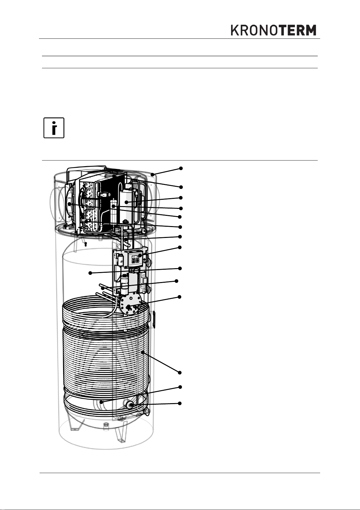
A
A
Device generator casing
B
Fan
C
Evaporator
D
Compressor
E
Dehydrator
F
Thermoekspansion valve
G
Controller
H
Hot sanitary water tank
(boiler)
I
Heat exchanger (heating
water)
J
Anti-corrosion anode
K
Condenser
L
Electric heater
M
Connection for additional
electric heater
C D E B F J
G
H
J
L
K I
M
3. Technical Description
3.1 General
This device is a heat pump for the heating of sanitary water in residential areas and small
business premises. When heating sanitary water, the heat pump also cools the area, from
which air is captured and / or returned to. The heat pump can thus along with heating of
sanitary water, be used for cooling of indoor areas, whereby it has to be emphasized, that
the heat pump will only cool the area, if there is a need to heat the sanitary water.
3.2 Components
Page 12

ID.: 17-16-20-2979-10
12
3.2018
WARNING
When heating with boiler or solar collectors, you may heat the water in the hot
water tank to a temperature above 80 °C whereby the safety thermostat switches
off. In such a case the thermostat has to be manually reset. To restart the
thermostat, an authorised installation technician must be called.
The device consists from the device generator (compressor, evaporator, fan, ...) and the hot
water tank. The housing of the generator is made of durable plastic and is heat and sound
isolated. The device has two attachments for air channels which enable a remote air intake
and exhaust from neighbouring rooms or the environment. The hot sanitary water tank is
equipped with a piped heat exchanger, which can be connected to an external fossil fuel,
biomass or solar energy collector powered boiler.
Hot Sanitary Water Tank
Sanitary water heater is enamelled with patented technology, heat isolated with polyurethane
and mechanically protected with sheet metal. The tank is serially equipped with a water heat
exchanger that can be connected with a boiler when choosing an additional heat source. An
Mg anode is also placed into the tank, preventing corrosion of the heater upon potential
mechanical damage to the enamel.
Electric Heater
The device is serially equipped with two electric heaters with a power of 2 x 2 kW, which
serves as an additional or backup heating source.
Along with both already installed heaters, it is possible to install an additional heater into the
hot sanitary water tank with a 6/4" attachment with separate power supply.
Anti-freeze probe
Regulator of heat pump senses the temperature of the vaporizer. In the case, that the
temperature of the vaporizer is below -7 °C, it will perform a safety shutdown of the device for
at least 30 minutes. In such a case, the heat pumps with an electric heater automatically
switch to electric heating and the heat pumps with an attached boiler switch to boiler heating
(circulation pump switch on).
Safety thermostat
The electric heater contains a safety thermostat with a limit at 85 °C. This means that, in the
case that the temperature in hot water tank is exceeded, the power supply will be switched
off and the device will stop operating. To restart the device, call authorised installation
technician who must verify and remove the reason of the safety shutdown of the device.
Boiler water temperature control
Monitoring and heating of water to desired temperature is ensured by the advanced
OPTITRONIC 2 touchscreen regulator.
In regards to the set up desired water heating temperature, the controller, as required,
switches the compressor and fan on or off, and, under certain conditions, also switches the
electric heater or circulation pump of the boiler on or off. The maximal temperature of water
heating that can be set up is 65 °C. Should the temperature in hot water tank increase over
75 °C, the controller switches off all sources of heat for safety reasons.
Minimal temperature of water in hot water tank is 7 °C.
High pressure cooling system protection
To prevent pressure in the cooling system to get too high and potential damage, related to it,
a high pressure safety switch is installed, which stops the operation of the heat pump in the
case of pressure rising beyond a preset point.
Conditions of operation
Environment temperature must be between -7 °C and +35 °C. The air must be clean with
relative humidity not exceeding 50% at +35 °C. At lower air temperatures, the relative air
Page 13
ID.: 17-16-20-2979-10
13
3.2018
5
6
4
7
8
3
10
1
2
9
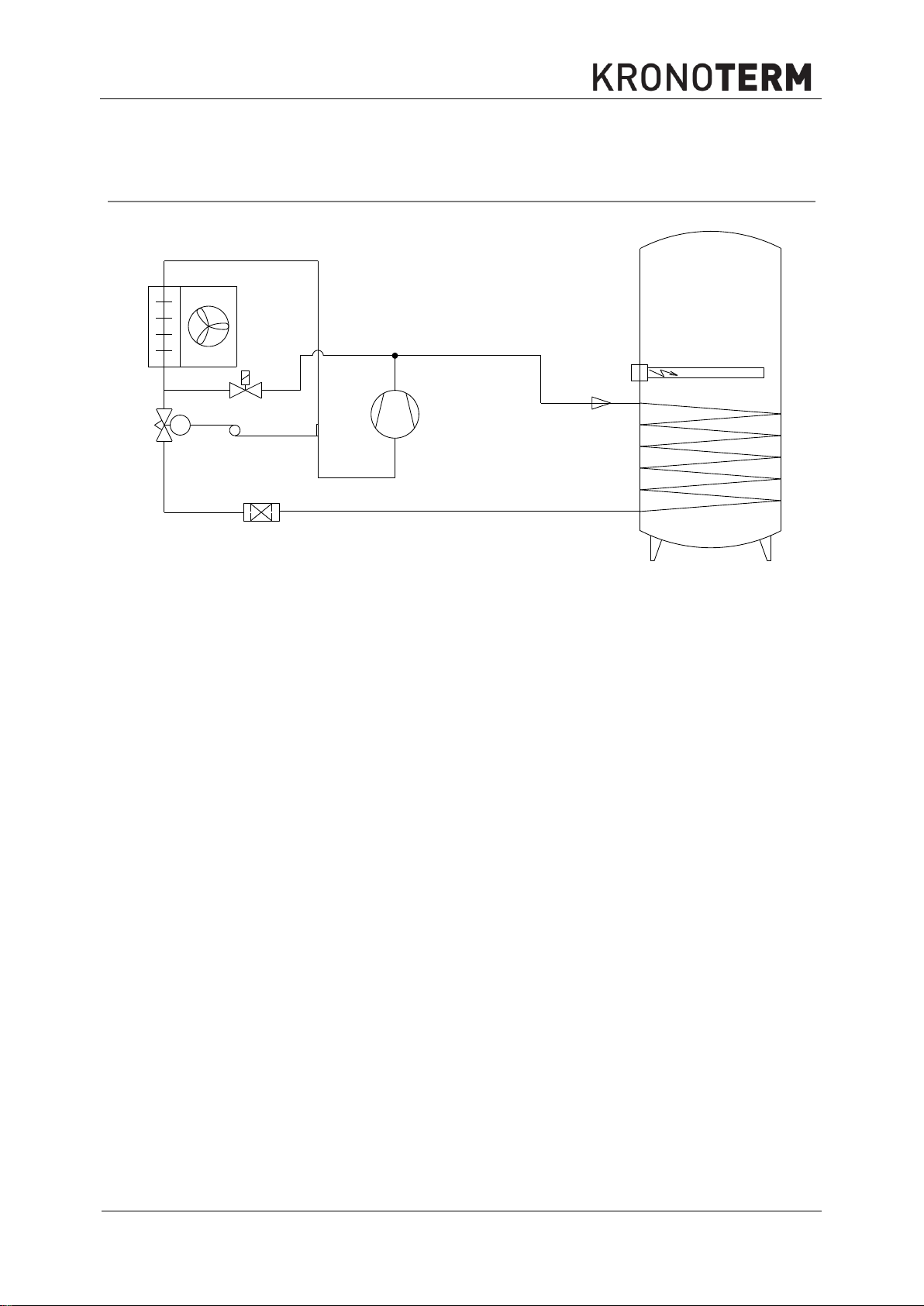
1. Compressor
6. Fan
2. Condenser
7. Magnetic valve
3. Dehydrator
8. Temperature bulb of the expansion valve
4. Thermoexpansion valve
9. Electric heater
5. Evaporator
10. Hot sanitary water tank (boiler)
The cooling system of the heat pump is a closed circuit system, within which the coolant R134a
circles as a heat exchanger. At lower pressure and lower temperature (e.g. 10°C), the coolant is
vaporised in the heat pump vaporizer, thereby drawing heat from the air. Then, the coolant is
compressed to a higher pressure in the compressor, which makes its temperature rise to the
temperature, higher than that of the water in the boiler. The coolant then gives away the heat to
the water in the condenser, whereby it liquefies. The expansion of the coolant, which makes the
coolant pressure and temperature lower to the primary value, the circular process is concluded.
This process is repeated throughout the heat pump operation time.
humidity may be higher. Devices, placed at higher altitudes above sea level may function
less efficiently due to lower air pressure.
3.3 Operation Principle
Page 14
ID.: 17-16-20-2979-10
14
3.2018
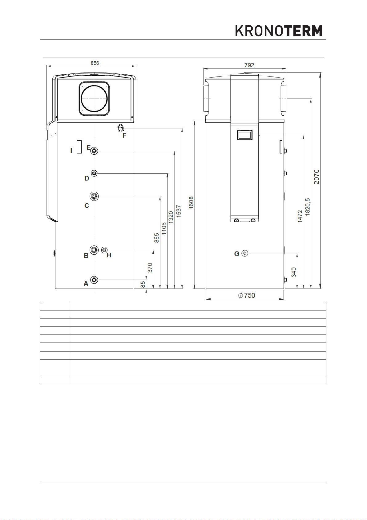
A
Connection cold water G1''
B
Connection heat exchanger – return pipe G1''
C
Connection heat exchanger – supply pipe G1''
D
Circulation connection G3/4''
E
Hot water connection G1''
F
Connection for removal of water condensation 16
G
Connection for additional electric heater 6/4''
H
Connection for the installation of a watertight tube with a threaded plug G1/2’’ for
the measurement of cold water temperature.
I
Channel for the temperature sensor of the heat exchanger
4. Position of Connections and Dimensions
Page 15
ID.: 17-16-20-2979-10
15
3.2018
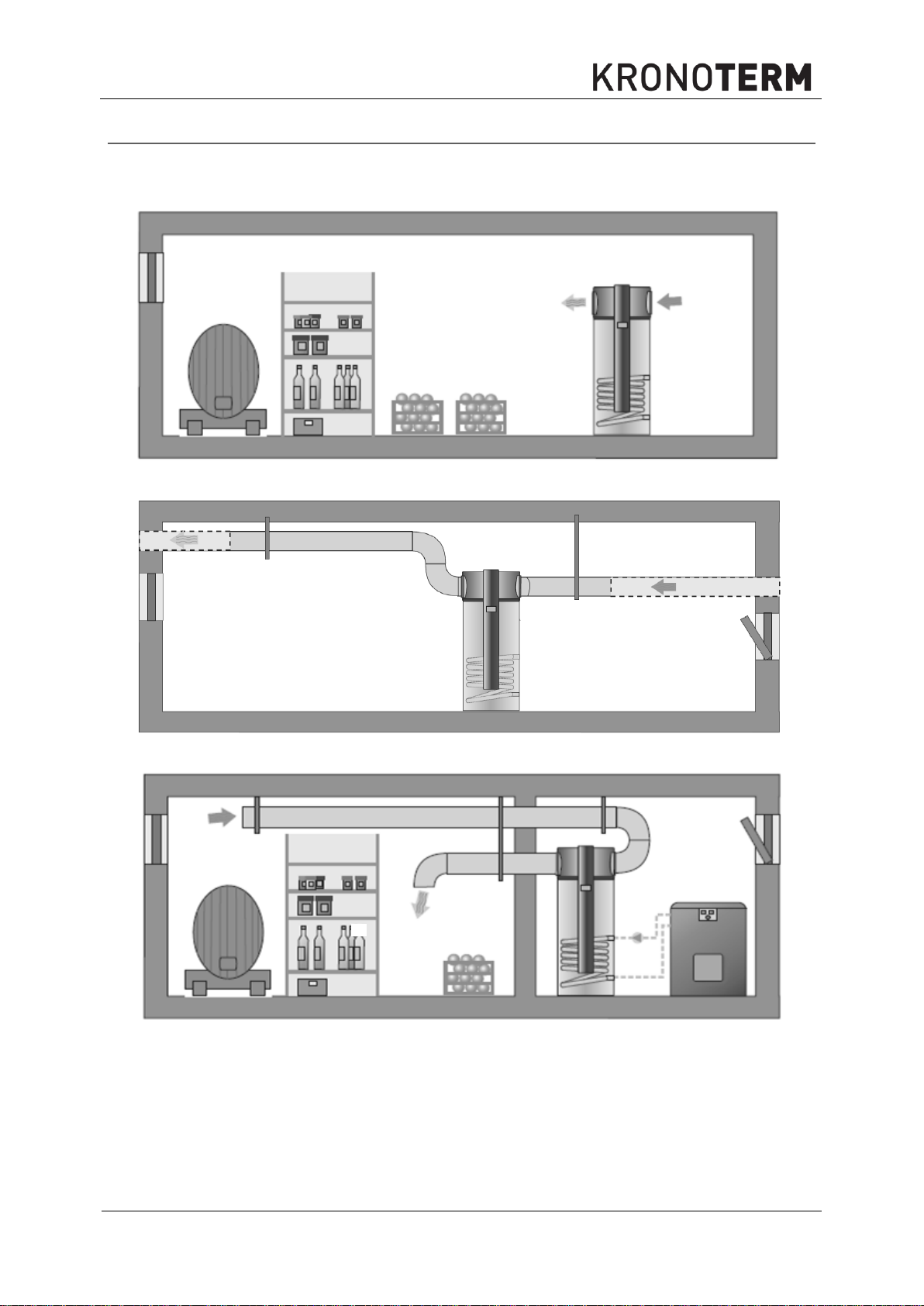
Figure 1: Suction and exhaust in the same room (e.g. pantry cooling).
Figure 2: Suction of the outside air, exhaust into the surroundings
.
Figure 3: Suction and exhaust into neighbouring room (e.g. pantry cooling).
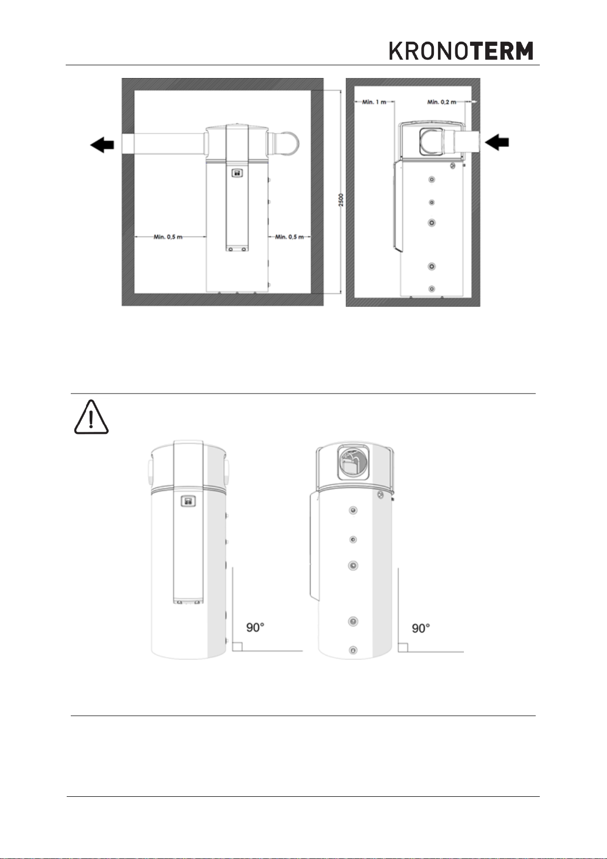
5. Installation
The lowest height of ceiling in the room must be 2500. The device is made so that it takes
heat from surrounding air or sucks it through air channels and blows it into neighbouring
rooms or the environment. The device may be installed in the following ways.
The most common placement of the heat pump is such, that the air is sucked from areas,
where there is a lot of waste heat. This air has a part of its heat removed, then released into
the surrounding. Air in kitchens, laundry rooms, sanitary facilities often contains unpleasant
odours, so it is blown into the environment. Thereby we must be careful that the air flows and
pressures in spaces are evened out, which must be ensured by the projecting engineer for
the ventilation.
Page 16
ID.: 17-16-20-2979-10
16
3.2018
WARNING
The device must not be placed where there are harmful substances, which
could damage it, in the air (barns, dangerous substance storage, open air,
etc.).
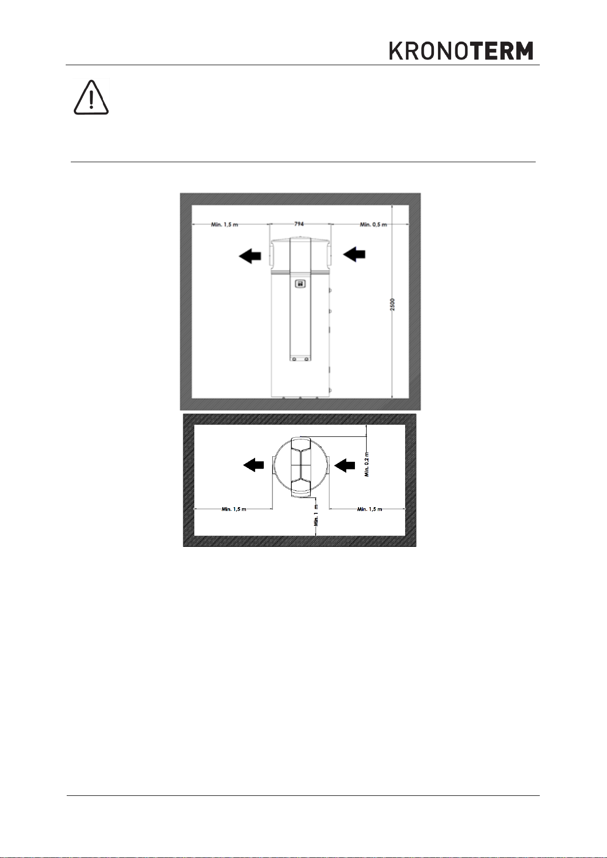
Figure 4: Minimal spacing between walls / ceiling in the case of air intake from the same room
5.1 Minimal spacing of the device:
The device may be placed into a room with or without installing air channels. This influences
minimal spacing from the walls, which depend on the direction of entry and exit of air.
Page 17
ID.: 17-16-20-2979-10
17
3.2018
Figure 5: Minimal spacing between walls / ceiling in the case of air intake from other rooms or the
environment
WARNING
The device must be in a vertical position during operation to prevent potential
leaking of water condensation.
In the case of using air heat from the same room where the device is installed, the room
must be at least 50 m3.
5.2 Device Levelling
Figure 6: Device levelling
The device has to be levelled as shown on the image above.
5.3 Hydraulic Connection
Hydraulic connection must be carried out in accordance with the valid national and local
regulations, which are in force for the connection of sanitary water tanks. The room with the
device must have a drain below the level of the device for the drainage in the case of a water
spill. The image below shows the proper hydraulic connection of the device.
Page 18

ID.: 17-16-20-2979-10
18
3.2018
WARNING
Due to use of different materials on the pipe installation, all connections (cold
water, hot water, circulation, heat exchanger) on the device must obligatorily be
galvanically isolated, or the corrosion of connections within the heat storage may
occur. We recommend galvanic separators from red alloy for each attachment, at
least 2x pipe diameter in length.
WARNING
The water tank is intended for potable water so it must obligatorily comply with the
valid national regulations on potable water, or device damage may occur and the
warranty is nullified.
1
Ball valve
5
Expansion vessel
2
Pressure reducing valve
6
Drain tap
3
Check valve
7
Circulation pump
4
Safety valve
8
Device generator
3
1
1
5
6
1
1
1
2
3
4
7
8
Safety valve setting [bar]
6
System pressure [bar]
3,0
3,5
4,0
Volume of sanitary water tank [L]
Expansion vessel [L]*
450
35
50
50
Should the heat exhanger (heating water) in the water tank not be used for water heating, it
must be filled with an anti-freeze liquid, to prevent corrosion in the exchanger. Only close a
full exchanger at the bottom (equalisation of pressure due to temperature changes).
Figure 7: Connection of device to plumbing network
Dimensions of expansion vessel:
* The actual size of the expansion vessel must be set by the installation technician / planner in regards to the size
of the system, in which the device will be installed.
Page 19

ID.: 17-16-20-2979-10
19
3.2018
WARNING
When installing the device obligatorily place expansion vessel into the system.
WARNING
Obligatorily install safety valve onto the inflow pipe, which has a nominal
pressure of 0,6 MPa (6 bar), and prevents the increase of pressure in the hot
water storage for over 0,1 MPa (1 bar) above nominal.
WARNING
For proper operation of expansion vessel, a suitable setting of the operational
pressure of the tank must be made. The pressure is set in regards to the
pressure in the plumbing. The setting needs to be checked every 6 months..
Air canal diameter
Maximal air canal length
Diameter 200 mm
10 m
Diameter 250 mm
15 m
5.4 Air Canal Installation
The device has attachments on left and right for the attachment of air canals, which enables:
the placement of the device into any room which is spacious enough
ventilation of desired room
exhaust of waste air or intake of fresh air from the environment
In the case of air canal use, keep in mind that air pipes and every additional knee represent
additional air resistance and lesser capacity of the device. Table 1 shows maximal permitted
canal lengths. Air canals must be isolated to prevent water condensation on the pipe
surfaces.
Figure 8 shows the device with air canal connections. The connections are 45 mm in length
and an outside diameter of Φ250. Access to inner parts is protected with mesh.
Figure 8: Air canal connection
Table 1: Maximal permitted air canal length.
The final length of air canals needs to take into consideration also the equivalent length of
accessories such as knees, reduction pieces, etc.
Page 20

ID.: 17-16-20-2979-10
20
3.2018
Accessories
Equivalent length in m
Knee 90° (Φ 200 mm)
3
Knee 90° (Φ 250 mm)
2
Reduction piece Φ250 x Φ200
1
Wall blind
2
Attachment of pipe for
condensation outlet to the device.
Siphon for prevention of
unpleasant odour seeping from
the drain.
NOTE
When installing a condensation outlet, pay CAUTION that the pipe is always at a
downwards incline with a siphon and water pillar of at least 5 cm at the outflow.
This prevents the suction of unpleasant odours from outlets.
Table 2: Accessories
5.5 Connection of Condensation Outlet
By removing heat from air, condensation of air moisture also occurs in the heat pump.
Depending on air temperature and relative air humidity, the production of moisture from air
varies. In some cases, no moisture will be removed from air and in others, up to 10 litres of
condensed water may be produced.
The water condensation outlet pipe must be laid in a way, where the water may always freely
flow out. Connect outlet pipe with drain. Should this not be possible, ensure a collection
canister, which must be regularly emptied.
Page 21

ID.: 17-16-20-2979-10
21
3.2018
WARNING
Due to use of different materials on the pipe installation, all connections (cold water,
hot water, circulation, heat exchanger) on the device must obligatorily be
galvanically isolated, or the corrosion of connections within the heat storage may
occur. We recommend galvanic separators from red alloy for each attachment, at
least 2x pipe diameter in length.
WARNING
Water used for sanitary water heating through the installed heat exchanger in the
hot sanitary water tank must comply with requirements of standard VDI 2035. The
heating system must be filled with soft water, which contains anti-corrosive and
anti-bacterial substances for prevention of corrosion. Before filling, the heating
system must be cleaned of all impurities.
The heating system must be thoroughly drained of all air. Prevent the intrusion of
air into the system, including diffusion air.
5.6 Connection of External Heating Source (alternative / additional source)
Sanitary water in the water storage tank may be heated with the device generator - heat
pump (primary source) and / or additional heat sources (serially equipped electric heater or
various external sources).
The external source is that which produces heat separately from the device and is
connected to the device through a pipe heat exchanger inside the DHW tank. External heat
sources are considered those which are available at all times (additional external electric
heater, fuel oil/gas/pellet/biomass boiler) or those which are at disposal only occasionally
(solar panels, wood-fired furnace, fireplace, etc.).
If a temperature sensor is installed into the external source the regulation checks the
temperature of the external source and adjusts the activation of the external source
circulation pump according to the need for domestic hot water and according to the
temperature of the external source. For proper functioning you must connect the circulation
pump and the temperature sensor correctly and set the parameters in the device controller.
For a proper electrical connection of the attachments follow the instructions in the chapter
about the electrical connection, and for the setting of the controller, the chapter on operation.
Page 22

ID.: 17-16-20-2979-10
22
3.2018
TYPE OF SUBSTANCE
UNIT
CONCENTRATION
INFLUENCE ON HEAT EXCHANGER
Organic sediments
mg/L
0
Ammonia NH3
mg/L
< 2
1 do 20
> 20
+
0
-
Chloride
mg/L
< 300
> 300 + 0
Allowed water hardness
°dH
5–10
Electrical conductivity
µS/cm
< 10
10–500
> 500
0
+
-
Iron (Fe) separate
mg/L
< 0,2
> 0,2
+
0
Free carbonic acid
mg/L
< 5
5–20
> 20
+
0
-
Manganese (Mn) separate
mg/L
< 0,1
> 0,1
+
0
Nitrates (NO3) separate
mg/L
< 100
> 100 + 0
pH value
mg/L
< 7,5
7,5–9
> 9
0
+
0
Oxygen
mg/L
< 2
> 2
+
0
Hydrogen sulphide (H2S)
mg/L
< 0,05
> 0,05 + -
HCO3- / SO
4
2
-
mg/L
> 1
< 1
+
0
Hydrogencarbonate (HCO3-)
mg/L
< 70
70–300
> 300
0
+
0
Aluminium (Al) separate
mg/L
< 0,2
> 0,2
+
0
Sulphates
mg/L
< 70
70–300
> 300
+
0
-
Sulphite(SO3)
mg/L
< 1
+
Chlorine (gas) (Cl2)
mg/L
< 1
1–5
> 5
+
0
-
WARNING
The heating system must be filled with water of a hardness between 5 °dH and
10 °dH . Device defects due to unsuitable heating water hardness are not
covered by warranty.
WARNING
Quality of potable water must comply with Potable Water Regulation (Official
Gazette of the Republic of Slovenia, no. 19/04, 35/04, 26/06, 92/06, 25/09).
This regulation complies with the European Council Directive 98/83/EC.
WARNING
For proper operation of active anti-corrosion protection, the hot sanitary water
tank (boiler) must be filled with water, the conductivity of which is at least
200 µS.
Maximal allowed content of individual substances in heated water and their influence on the
heat exchanger are shown in the table below. The heated water which includes any
substance in a concentration which causes corrosion (influence "-") in the heating system is
forbidden. The heating water which contains two or more substances in a concentration,
which may cause corrosion (influence "0") in the heating system is also forbidden.
Table: Influence of various aggressive substances in heating water onto the durability of hot
sanitary water tank (+ = no influence, 0 = danger of corrosion, - = corrosion – use forbidden).
Page 23

ID.: 17-16-20-2979-10
23
3.2018
1
Ball valve
7.1
Circulation pump (SET SOLAR)
2
Pressure reduction valve
8
Device generator
3
Check valve
9
Furnace
4
Safety valve
10
Heating water hopper
5
Expansion vessel
11
Solar energy collectors
6
Drain tap
dT
Differential thermostat
7
Circulation pump
dT1
External differential thermostat
3
1
1
5
6
1
1
1
1
2
3
4
1
7
1
1
7
1
9
8
3
1
1
5
6
1
1
1
2
3
7
1
1
1
3
7
1
4
5
4
11
8
Below, there are several possible connection schemes for external sanitary water heating
sources.
Figure 9: Heat pump combined with furnace.
Figure 10: Heat pump combined with solar collectors.
Page 24

ID.: 17-16-20-2979-10
24
3.2018
1 2 3 1
1
3
1
7
4 5
6
1
11
3
1
1
7.1
3 1
4
5
9
12.3
1
12.2
4
5
7
1
12.1
8
1
1
1
12
dT
12.4
A
B
C
D
Figure 10: Heat pump combined with solar collectors and furnace (SET SOLAR)
Page 25

ID.: 17-16-20-2979-10
25
3.2018
NOTE
To ensure a safe and efficient operation of the additional heat source for the
preparation of sanitary water (boiler, solar collectors), the controller of the external
source needs to be set to a limit of water heating of max 75 °C. It is recommended
to set the temperature at 65 °C or less.
The highest permitted water temperature in the heat exchanger is 110 °C.
A
B
5.7 Placement of External Controller Temperature Probe
In the case of use an external controller of additional source, attach temperature probe of the
external controller into the appropriate canal on the right side of the device, under the black
plastic cap (A), as marked on the image.
Figure 9: Temperature probe canal on the right side of the device
B connection ½'' is intended for installation of the watertight tube of an additional sensor for
the measurement of cold water temperature in the device. The connection is used in
applications where the temperature of the entire water heater volume must be checked with
an external controller.
Page 26

ID.: 17-16-20-2979-10
26
3.2018
1
Ball valve
7
Circulation pump
2
Reduction valve
8
Reduction valve
3
Check valve
9
Device
4
Safety valve
A
Cold water
5
Expansion vessel
B
Hot water
6
Release valve
C
Circulation
3
1
1
5
1
1
2
3
4
7
10
6
3
1 1 1
1
1
3 3 3
10
6
10
6
10
6
DN 25 DN 25 DN 25 DN 25
DN 25DN 25DN 25DN 25
DN 25 DN 25 DN 25 DN 25
9 9 9 9
C
B
A
5.8 Parallel Connection of Several Devices
In case of a need for large quantities of hot water, you can install several devices in a parallel
fashion. For appropriate operation, the installation must comply with the instructions below.
5.8.1 Connection of Cold - Hot Water and Circulation
Page 27

ID.: 17-16-20-2979-10
27
3.2018
1
Ball valve
6
Release valve
2
Reduction valve
7
Circulation pump
3
Check valve
8
Reduction valve
4
Safety valve
9
Device
5
Expansion vessel
10
Boiler
9
Device
A
Intake canal
B
Exhaust canal
Number of devices
Length of
canals
1 2 3 4 5 6 7 8 9
10
10 m
20 m
30 m
10
B
A
5.8.2 Connection to Boiler
5.8.3 Air Canal Connection
Table: Internal diameter of pipes depending on length of canals and number of devices.
Largest allowed pressure drop on an individual device is 55 Pa.
Page 28

ID.: 17-16-20-2979-10
28
3.2018
WARNING
Connection of the device to the power grid must take place in accordance with
standards for connection to electrical grids. The device must be connected to the
electrical grid via a shutdown element, built into the electrical installation according
to valid regulations. The shutdown element must separate all contacts under the
conditions of overload category III.
DANGER
The device must be connected to the electricity supply where the RCD (FID) switch
of type A is installed.
5.9 Electric Connection
Electric connection of the supply cable, external signal, additional temperature probe, and
additional heater is done under the cover on the front of the device. To access electrical
connections the front cover must be removed as shown below:
Figure 10: Front cover removal
All electrical connections are carried out on the bottom holder, where electrical pins with
cable release pins are prepared.
Page 29

ID.: 17-16-20-2979-10
29
3.2018
1
A
1
2
1 2 3 4
a
b
c
Figure 11: Connection pin holder
5.9.1 Power Supply:
Power supply is carried out via pins marked with 1. Three connections of power supply
are possible:
a) Single-phase connection with maximal current load of 16 A is done on pins in the
area a, using pins N and L.
b) Single-phase connection with maximal current load of 25 A is done on pins in the
area b, using pins N and L.
c) Three-phase connection with maximal current load of 2x16 A is done on pins in the
area c, using pins N, L1, L2 and L3.
With all three connection types, the pin is used for earthing, and the pin N for a neutral
lead. 1f detailed connection is described below in points a and b while the 3f connection is
described in point c.
a. Single-phase connection with maximal current load of 16 A
This connection is used when single-phase power supply with 16 A fuses is available. In this
connection type connect power supply phase to pin 3. This is connected to pin 4 with a
bridge (factory connection).
This connection enables the operation of device generator and the first installed electric
heater (2 kW). The second heater is not active in such a case.
Supply cable needs to have a circumsection of 3 x 2,5 mm2.
Maximal total electrical power for this connection is 3,5 kW.
Page 30

ID.: 17-16-20-2979-10
30
3.2018
ATTENTION:
In three-phase connection, it is obligatory to remove the bridge which is factory
placed and connecting pins 3 and 4.
WARNING
Connection pins of the temperature probe for the external heat source are under 5
V tension.
2
B1 B2 C1 C2 D1 D2 D3 A1 A2
b. Single-phase connection with maximal current load of 25 A
This connection is used when single-phase power supply with 25 A fuses is available. In this
connection type, connect power supply phase to pin 3. This is connected to pin 4 with a
bridge (factory connection).
To connect the second electric heater (2 kW) it is necessary to additionally connect the
bridge between connection pins 4 and 5.
This enables the operation of the device generator and both installed electric heaters (2 x 2
kW).
Supply cable needs to have a circumsection 3 x 4 mm2.
Maximal total electrical power for this connection is 5,5 kW.
c. Three-phase connection with maximal current load of 3 x 16 A
This connection is used when three-phase power supply with 3x16 A fuses is available. In
this type of connection, every phase is connected to an individual pin (1, 2, 3, 4 and 5).
This enables the operation of the device generator and both installed electric heaters (2 x 2
kW).
Supply cable needs to have a circumsection 5 x 1,5 mm2.
Maximal total electrical power for this connection is 5,5 kW.
5.9.2 Additional Heat Source Connection
Left connection pin is intended for the connection of the circulation pump, external
switch and temperature probe of the external source.
Temperature probe of the external heat source must be connected to pins with markings
B1 and B2. To measure external heat source temperature (differential thermostat) use
temperature probe of the NTC type (10K 1% BETA 3435 1%). Temperature probe power
supply is 5 V.
Page 31

ID.: 17-16-20-2979-10
31
3.2018
WARNING
The appliance must never function without water in the hot water tank.
WARNING
Bring the tension of ~ 230 V on the pins of the external signal and circulation pump.
A
External signal switch is used to switch on various device functions. Connect external
switch on positions C1 and C2.
Circulation pump must be connected to the pins under the markings D1, D2 and D3.
Connect the steady voltage of ~230 V to D1 and D2 and the neutral lead, and use D3 for the
earthing lead. Maximal load of the circulation pump is 300 W.
Connection of Additional Electric Heater Activation (option)
The holder (figure 11) allows you to use location a to install an additional connector
for the activation and supply of an additional electric heater, installed on the G
connection (figure in chapter 5) at the bottom of the hot sanitary water tank. The
electric heater is available from the manufacturer as an accessory.
Control pins of the contactor (A1, A2) should be connected to the pins under the mark
add. (figure 13) on the pin holder. Then connect the electric heater to the connector,
which you must ensure an external power supply for.
6. Device Startup
6.1 Filling Device with Water
After a professional attachment of the heat pump onto the plumbing, the system needs to be
filled with water and air thoroughly removed from it. This is done by opening all faucets in the
apartment. When water flows without interruptions from all faucets, there is no more air in the
system.
6.2 Controls Before Startup
Before device start-up, the following controls have to be carried out:
Hot water tank must be filled with water and air thoroughly removed from it.
All hydraulic connections must be tightly sealed.
Suitable expansion vessel and appropriate safety valve must be built in.
All safety elements must be operational.
6.3 Device Startup
After the device is connected to the electricity supply, the device starts to heat the water
in the NORMAL program (chapter 7.3.3). The controller display shows clock setting (chapter
7.3.9). Should the clock be factory set, the display shows the basic temperature of sanitary
water after activation (chapter 7.1.1).
Page 32

ID.: 17-16-20-2979-10
32
3.2018
The interface of device controller OPTITRONIC 2 consists of a colour LCD display and four
function keys for operation.
back / screensaver
increase value
forward / confirm / menu
decrease value
system statuses
LCD screen displays currently
measured sanitary water
temperature
sanitary water
temperature
Operation of compressor and backup source
Alternative / additional source state
Device generator heating sanitary water
Internal electric heater active
Backup source programme active
External source active
Device on standby
Internal heater and external source active
Device in startup mode
Active programme
Warningsa nd defects
Anti-freeze programme active
External input influencing operation
Defrosting programme active
Warning
Quick water heating programme active
Error
Overheating - anti-legionella programme active
Operation mode
Holiday programme active
COMFORT PLUS programme active
NORMAL programme active
ADDITIONAL SOURCE programme active
ECO programme active
OFF programme active
COMFORT programme active
PHOTOVOLTAICS (PV) programme
active
1
2
3 4 5
7. Controller
7.1 Basic Window
7.1.1 Sanitary Water Temperature
7.1.2 System statuses
Display current device operation. The statuses show the active operation programme, functioning of
individual system components and potential errors and warnings.
Legend of system statuses:
Page 33

ID.: 17-16-20-2979-10
33
3.2018
Enter into screensaver window with .
When we aren't using the controller, the
screen displays screensavers. Those are
meant for quick display of important heating
system information. Presence of individual
screensavers depends on the activities and
individual functions, type of heat pump and
presence of module Optitronic WEB Module.
Move between windows with the key .
Exit from screensaver view with the key .
Display of device
time
Display of external
source temperature
Display of incoming
air temperature
Display of system
warnings
See chapter 9.1.
Display of system
errors
See chapter 9.2
7.1.3 Setting of Desired Temperature of Sanitary Water
In the basic window, by pressing or we begin setting the desired temperature of
sanitary water.
Currently set desired temperature is displayed. By pressing the key or the value is
increased or decreased. To confirm change of desired sanitary water temperature, press .
7.2 Screensavers
7.2.1 All screensavers
Page 34

ID.: 17-16-20-2979-10
34
3.2018
Display of time and date. Time and
date are automatically
synchronised with local time via the
Water Cloud server.
Display of connection status
with the cloud (server Water
Cloud).
Display of connection status for
local network connection.
Enter menu with key.
Move between menus with keys or .
Use key to enter desired submenu.
Use keys or to select desired setting in
submenu.
Use key to confirm new setting. If you
wish to cancel the change, use key to
return to menu.
Orange indicators indicate current selection on
the controller.
Additional screensavers for built in Optitronic WEB module (option):
7.3 Menu
In the basic window, by pressing , we enter into the menu. The menu contains settings
and programmes of device operation.
Page 35

ID.: 17-16-20-2979-10
35
3.2018
In the case of one or several errors on the device, the menu displays a new
setting "Error Acknowledgement". After acknowledging an error the device
will restart and check if the cause of error has been removed. If the error has
been removed, the setting "Error Acknowledgement" is not visible in the
menu any more.
Enter "Error
Acknowledgement"
setting with the key
.
Use key to acknowledge errors.
The menu shows up again.
The programme for quick heating is intended for one time quick water heating
with the device and chosen additional heat source at the same time (chapter
8.3.2). After achieving a temperature, the quick heating programme switches
off and changes to previous operation mode. The programme is started by
selecting the setting »START«.
Using direction keys and select between basic device operation
programmes. Confirm selection with the key .
NOTE
Additional operation programmes such as "Quick water heating"
(chapter 7.3.2), "Daily schedule" (chapter 7.3.6), "Vacation"
(chapter 7.3.8), etc. have priority over basic operation programmes.
Operation programme NORMAL
Operation programme COMFORT PLUS
Operation programme ECO
Operation programme OFF
Operation programme COMFORT
Operation programme ADDITIOLAN SOURCE
In the ECO operation programme, the device heats water to desired
temperature while considering a negative deviation. The desired deviation is
chosen with keys and . Setting is confirmed with the key .
Setting range: 0 °C – 15 °C.
Setting step: 0,5 °C.
In the COMFORT operation programme, the device heats water to desired
temperature while considering a positive deviation. The desired deviation is
chosen with keys and . Setting is confirmed with the key .
Setting range: 0 °C – 15 °C.
Setting step: 0,5 °C.
7.3.1 Error Acknowledgement
7.3.2 Quick Water Heating
7.3.3 Basic Operation Programme
7.3.4 Temperature Deviation ECO
7.3.5 Temperature Deviation COMFORT
7.3.6 Daily Schedule
Page 36

ID.: 17-16-20-2979-10
36
3.2018
A change of operation programme can be automatic by setting up a daily
schedule. Every daily schedule may have two time intervals. Every interval
has a set starting time, ending time, and programme of operation. In the time
outside the set intervals of the schedule, the device operates according to
basic programme.
Move between schedule setup windows with the key .
Enter schedule
setting with the
key .
Turn schedule
»ON« or »OFF«.
Set starting time of
schedule interval.
Set ending time of
schedule interval.
Set operation
programme in the
time of interval.
The schedule may be set for every day in the week separately. Every daily
schedule can have up to three time intervals. Every interval has a set starting
time, ending time, and programme of operation. In the time outside the set
intervals of the schedule, the device operates according to the basic
programme.
NOTE
To set and operate weekly schedules, the device needs to be
equipped with the Opritronic WEB module (option).
Move between schedule setup windows with the key .
Enter schedule
setting with the
key .
Pick the day of
the week
(1-Monday
7-Sunday).
Turn schedule
»ON« or
»OFF«.
Set starting time
of schedule
interval.
Set ending time
of schedule
interval.
Set operation
programme in
the time of
interval.
The devices with guided air, along with sanitary water heating, also enable
cooling and ventilation of rooms. Ventilation functions according to set
intervals of a ventilation schedule with set start and end times.
NOTE
To set and operate weekly ventilation schedules, the device
needs to be equipped with the Optitronic WEB module (option).
7.3.6.1 Weekly Schedule (option)
7.3.7 Ventilation Schedule
Page 37

ID.: 17-16-20-2979-10
37
3.2018
Move between schedule setup windows with the key .
Enter schedule setting
with the key .
Turn schedule »ON« or
»OFF«.
Set starting time of
schedule interval.
Set ending time of schedule
interval.
NOTE
Ventilation according to timetable is blocked when the defrosting function is in progress.
(chapter 8.3.6).
The vacation programme allows us to shut down the device for a specific
number of days when we know we will not require hot water. In this
period, no programme is active, even if it's set on a schedule. When the
set time interval passes, the device automatically switches back to basic
operation programme.
NOTE
In the case that the vacation programme was activated and in
operation at least for 1 day, the overheating programme will
activate after the ended vacation programme (chapter 7.3.11)
Move between schedule setup windows with the key .
Enter vacation setting
with the key .
Turn vacation
programme »ON« or
»OFF«..
Set number of days
(duration) of vacation
programme.
Manual setting of time on the device.
NOTE
In case that your device has the Optitronic WEB module (option) installed
and is connected to the server Water Cloud, the time and date of the
device are automatically synchronised with the server Water Cloud.
Manual activation and deactivation of the programme Backup Source
(chapter 8.3.1)
7.3.8 Vacation
7.3.9 Time
7.3.10 Backup Source
Page 38

ID.: 17-16-20-2979-10
38
3.2018
Programme heats water to 65 °C, to remove potential legionella bacteria.
Activation can be automatic or manual.
NOTE
The device overheats water and destroys the Legionella bacteria in
the water tank. For complete disinfection a hot water flow through
all pipes of the water installation must be ensured.
NOTE
Factory preset overheating is automatic every 14 days. We advise
against overheating too often, as energy consumption during
overheating is 1/3 higher than during normal operation.
Programme "Quick water heating" (chapter 8.3.2) can be triggered automatically
when water temperature falls below the set value.
Move between setup windows with the key .
Enter setting with the
key .
Turn programme »ON«
or »OFF«...
Set temperature at which
the "Quick Water
Heating" programme
activates.
Screen brightness settings.
Parameters from lowest to full brightness:
In the System information menu data on software and hardware of the
controller, display and Optitronic Web module (optionally) are given.
7.3.11 Overheating Programme - Anti-legionella
7.3.12 Automatic Quick Water Heating
7.3.13 Screen Brightness
7.3.14 System Information
Page 39

ID.: 17-16-20-2979-10
39
3.2018
Move between setup windows with the key .
Enter setting with the key
.
Data about graphic panel
OPTITRONIC 2.
Data about main
controller
OPTITRONIC 2.
Data about module
Optitronic WEB module
(option).
Menu allows access to advanced
controller settings by entering a 4digit security PIN code.
PIN koda: 1234
Use keys and to
select number and the key
to move to the next field.
Overheating programme (chapter 7.3.11) can be set to work on schedule.
Factory setting is a repetition of the programme every 14 days. (Settings allow
for periods of 1 - 99 days).
If we do not wish to use automatic overheating, the period is set to OFF.
WARNING
The overheating period must obligatorily be set in regards to the
national regulation requirement for safe preparation of hot sanitary
water.
Additional source function (chapter 8.2) allows the activation of one or a
combination of heat sources. (Selection depends on heat pump type and
presence of other heat sources in the heating system):
Internal electric heater.
Internal electric heater and external
source.
External source.
Deactivation of additional source
function.
The device may be set to change operation programme upon detecting
an external input signal.
The external input signal may be triggered by a switch (key) or external
device signal (furnace, solar photovoltaic panels, electric counter, etc.).
Several operation programmes are possible:
NORMAL: Switch to programme
NORMAL
OFF: Remote switch to programme OFF during
longer absence from home (device is not in use
for a prolonged time).
ECO: Switch to programme ECO when
power tariff is higher to reduce heating
costs.
Quick water heating:
Remote programme activation.
COMFORT: Switch to programme
COMFORT when power tariff is lower to
increase efficiency of operation.
PHOTOVOLTAICS: Solar photovoltaic system.
7.3.15 Advanced Installation Settings
7.3.15.1 Automatic Overheating Programme - Anti-legionella
7.3.15.2 Additional Source Selection
7.3.15.3 External Input
Page 40

ID.: 17-16-20-2979-10
40
3.2018
COMFORT Plus: Switch to programme
COMFORT Plus, when power from
solar panels is available.
Backup source: Activation of backup source
programme.
Function input 1
Function input 2
Function input 3
When water reaches desired temperature, the heating switches off and
enters standby mode until water temperature doesn't drop for the standby
level difference.
Factory setting for standby difference 7 °C.
Setting area: AUTO or 2 °C – 10 °C.
Setting step: 0,1 °C..
Example: Water heating will deactivate after reaching the desired
temperature 55 °C. Heating will reactivate once temperature drops for the
standby difference 7 °C, thus to 48 °C.
Device in the programme PHOTOVOLTAICS - PV (solar photovoltaic
system) (chapter 8.3.4) heats sanitary water to PV temperature setting.
The factory setting is 70 °C.
Setting range: 55 °C – 75 °C.
Setting step: 0,5 °C..
When the temperature of sanitary water in the programme PV (chapter 8.3.4)
drops under the set desired temperature for the programme PV for the
temperature deviation value (»Standby in PHOTOVOLTAICS Programme«),
the device resumes heating the sanitary water.
Factory temperature deviation setting is 3 °C
Setting range: 1 °C – 20 °C.
Setting step: 0,1 °C
7.3.15.4 Standby Setup
Dynamic standby:
In case of setting the standby temperature to AUTO, the standby temperature changes in
regards to the set desired water temperature. If the temperature set is 40 °C, standby
temperature difference is 5 °C, while in the case of water temperature 55 °C and more,
standby equals 10°C. Between temperatures 40 °C and 55 °C the standby temperature
difference is calculated in a linear way between 5 and 10 °C.
Static standby:
Other standby settings are static and are the same for all water temperatures. The minimal
temperature difference is thus 2 °C, and the maximal 10 °C. Factory standby difference is set
to 7 °C.
7.3.15.5 Temperature Settings for PHOTOVOLTAICS Programme
7.3.15.6 Standby in PHOTOVOLTAICS Programme
Page 41

ID.: 17-16-20-2979-10
41
3.2018
In the case of external source use, maximal temperature is set, up to which
the external source may heat water. The standby temperature in this mode is
set to a fixed value of 10 °C.
Factory temperature setting is 60°C.
Setting range: 20 °C – 75 °C.
Setting step: 0,5 °C
The setting defines the operation of device generator and external
source regime (chapter 8.2.2)
Priority external source
Priority device generator
NORMAL: For heating water to desired temperature (chapter 7.1.3), the device uses
the primary heat source (compressor) whenever it is possible. When the primary
heat source, due to conditions (e.g. entering air temperature) can not provide
enough power, the device adds the additional power source (e.g. electric heater) to
aid in water heating.
ECO: Water is heated to desired temperature (chapter 7.1.3), with a considered
negative deviation ECO. The final water temperature is lower than in the NORMAL
mode. ECO deviation setting can be found in the user menu (chapter 7.3.4).
COMFORT: Water is heated to desired temperature (chapter 7.1.3) with a
considered positive deviation COMFORT. The final water temperature is higher than
in the NORMAL mode. COMFORT deviation setting can be found in the user menu
(chapter 7.3.5)
COMFORT PLUS: Water is heated to desired temperature (chapter 7.1.3) with a
considered positive deviation COMFORT. Water is heated by generator of the
device and internal electric heater at the same time. »COMFORT PLUS programme
may be stated manually (chapter 7.3.2), automatically (chapter 7.3.12) or via
external input (chapter 7.3.15.3).
OFF: The device is off.
ADDITIONAL SOURCE: The water is heated to the set temperature of the
additional source (Chapter 7.3.15.7) with a chosen additional source. The type of
the additional source is important and thereby the setting of the mode of operation of
the additional source and a possible connection of the temperature sensor of the
external source.
7.3.15.7 Setting of Temperature of External Source Programme
7.3.15.8 Setting of External Source Use Priority
8. Device Operation Setting
8.1 Basic Operation
Compressor is used for primary water heating. The compressor operates in a limited
temperature area of entering air (from -7 °C to 35 °C). Outside this area, the controller shuts
down compressor operation for safety reasons. The compressor may heat water to a maximal
temperature of 65 °C.
8.1.1 Basic Operation Programmes
Page 42

ID.: 17-16-20-2979-10
42
3.2018
8.2 Additional Source
For the functioning of the backup source, the following must be done correctly:
Choosing the type of backup source,
Choosing the operation mode of the external source,
Making an electrical connection between the external source and
If needed, connecting the temperature probe of the external source.
The backup source can be triggered automatically by the air temperature outside the
operating range of the device’s generator or possible malfunction of the device’s generator or
by choosing the differential operation of the backup source or the backup source can be
triggered manually by choosing the operation among the basic operation programmes or the
schedule or by the external signal. Heating with the additional source can also be triggered
when the combined programmes “Quick water heating”, “Comfort plus” and “Automatic quick
water heating” are activated.
8.2.1 Correct choice of the additional source
For correct operation of the additional source it is necessary to choose a backup source to
heat the water (chapter 7.3.15.2). The factory choice is an electric heater built into the
device.
In case of using the external heating source, it is necessary to choose the fire icon or the
fire with heater icon ( or ).
8.2.2 Choosing the correct operation mode of the external source
In case of choosing an external heating source as additional source, it is necessary to
determine how the external source will operate (chapter 7.3.15.8).
8.2.2.1 The device's generator priority (additional external electric heater, furnace
oil/gas/pellet/wood biomass ...)
The operation mode of the external source with the device's generator priority is
used in cases when the external source is always available. These methods of
heating are the additional external electric heater, furnace oil/gas/pellet/wood
biomass ... This kind of operation mode means the controller in its basic mode will
always use the primary source (the device's generator) for heating DHW. The external
heating source will be used only when the air temperature is outside the operating range or if
the device's generator is out of order.
Heating only with the external source can be chosen manually with the basic programme
"Additional source « with a set schedule or a set external signal. It can also be used
together with the combined programmes "Quick Water Heating «, »Automatic quick water
heating« and »Comfort plus (only electric heater) «.
Installing an additional temperature sensor for the external source is not obligatory, but it is
preferred. Not using the sensor can result in the external source not being warm enough and
the cooling of the heat pump boiler.
To turn on the external source temperature verification, your authorized installer must
activate the parameter in the service menu.
Operation of the external source temperature verification with the device's generator
as priority:
When the need for the external source arises, the device turns it on via the electric signal
(turning on the external source's circulation pump at the same time). Checking the operation
of the external source is performed by comparing the temperature of the external source with
the temperature of the heat pump boiler. When the temperature of the external source is at
Page 43

ID.: 17-16-20-2979-10
43
3.2018
least 5 °C higher than the temperature of the buffer tank for DHW, the external source is
available and is used for heating water. When n-minutes elapse after turning on the external
source and its temperature is not higher than 5 °C, the electrical signal for turning on the
external source turns off for 3 x n-minutes; then the start-up process is repeated. If after three
successive trials the start-up of the external source is unsuccessful, the device displays error
E07, which has to be confirmed manually 7.3.1).
8.2.2.2 External source priority (solar collectors, wood furnace, fireplace ...)
The operation of the external source with external source priority is used in cases
when the external source is available only occasionally. These kinds of heating
methods are solar collectors, wood furnaces, fireplaces ... This operation mode's
regulation for heating DHW will use the device's generator in its basic operation
mode; if the temperature of the external source is high enough, the device's generator will
turn off and heating with external source will be activated. The water will be heated up to the
set temperature of the backup source (chapter 0).
When the water temperature in the device's buffer tank approaches the external source's
temperature (the difference in temperature must be 10 °C), the heating with external source
turns off, heating continues with the device's generator.
With this mode of heating using the external source, the use of a temperature sensor in the
external device is obligatory; if the temperature sensor is not connected, the regulation
displays error E02 (chapter 9.2). Connecting the sensor is described in chapter 5.9.2.
In case the basic programme "Additional source « is chosen, heating the water will only be
performed in case the external source will have enough heat and not otherwise.
8.3 Additional Operation Programmes
8.3.1 Backup Source
In case of a malfunction on the device's generator, the device automatically goes
into temporary operation in some cases (»Anti-freeze programme« - chapter 8.3.3).
Water is heated with the chosen additional source or internal electric heater up to
the temperature of the Anti-freeze programme (35 °C). In case we want to have the
water heated up to the temperature defined by the basic programme despite the malfunction
in the generator, the backup source programme (electric heater) must be chosen manually.
This ensures temporary operation for the period until the arrival of a qualified service
company and the correction of the error.
8.3.2 Quick Water Heating
The quick water heating programme is intended for quick water heating with the
device generator and selected additional source (chapter 7.3.15.2) at the same
time. After reaching the set temperature, the quick heating programme turns off and
switches back to previously set operation mode.
Quick water heating programme may be stated manually (chapter 7.3.2), automatically
(chapter 7.3.12) or via external input (chapter 7.3.15.3).
Operation differs in regards to the set additional source (chapter 7.3.15.2):
Internal electric heater:
Water is heated by generator of the device and internal electric heater at the same time.
External source:
Water is heated by generator of the device and external source (if available).
Internal electric heater + external source:
Water is heated by generator of the device, internal electric heater and external source (if
available)
setting:
Page 44

ID.: 17-16-20-2979-10
44
3.2018
NOTE
If additional source is not selected (chapter 7.3.15.2), or external source is not
available (chapter 8.2.2.2), the programme will activate internal electric heater.
NOTE
SETTING: In the menu EXTERNAL INPUT (chapter 7.3.15.3) select parameter
»PHOTOVOLTAICS (PV)« .
NOTE
The operation of the ventilation schedule programme (chapter 7.3.7) is disabled
during the "Defrost" programme.
Water is heated only by generator of the device.
The temperature to which the water is being heated by the programme of quick heating
depends on the programme in which the device operates:
Basic operation programmes:
Water is heated to temperature, defined by programme COMFORT.
Additiolan source programme:
Water is heated to temperature, set in the menu SETTINGS OF EXTERNAL SOURCE
TEMPERATURE (chapter 0).
8.3.3 Anti-freeze Programme
The anti-freeze programme is activated automatically and ensures that, in the
case of a compressor defect, the system does not freeze.
The water heating programme uses heat from the selected additional source
(chapter 7.3.15.2)
8.3.4 PHOTOVOLTAICS
The programme photovoltaics (PV) is a programme of device operation which
heats water with excess electrical power, obtained through a solar photovoltaic
system. The programme activates when the device receives a PV signal via
external input (chapter 7.3.15.3).
When the PV signal is present, the device generator heats water to maximal work margin
of the compressor temperature (65°C), and from there on to the set temperature of the
programme photovoltaics (chapter 7.3.15) water is heated by the internal electrical heater.
If external source is mounted to the heat pump (chapter 8.2.2.2), the external source will be
used for heating when it is available.
8.3.5 "Bivalent mode" Programme
The power of the device at an air temperature of below 3 °C is reduced, this is why to
achieve quick water heating, the chosen additional source activates together with the
compressor (chapter 7.3.15.2).
The bivalent mode program turns off when the air temperature is above 6 °C for 30 min.
8.3.6 "Defrost" Programme
At low air temperatures, frost forms on the evaporator which lowers the efficiency of
the device's operation. To thaw the frost, the controller activates the defrost
program.
The device's generator is activated during defrosting but it defrosts the evaporator
instead of heating water. During defrosting, heating the DHW is performed by the electric
heater.
The fan is turned off during defrosting.
Page 45

ID.: 17-16-20-2979-10
45
3.2018
During the "Defrosting" programme, the display shows the defrosting icon .
9. Errors and Warnings
9.1 Warnings
Warnings on the screen of the controller are shown with a yellow triangle and codes
W01-W07. Codes have following meanings:
WARNING W01 - Entry Air Temperature Too Low
If the entry air temperature drops under minimal air temperature (-7°C), the generator of the
device is shuts down. Water is heated by the additional heat source, if one is selected
(chapter 7.3.15.2). Blockage of the heat pump unit is eliminated when the air temperature is
3 °C above the minimum air temperature (above -4 °C) for 30 minutes.
The warning is shown while the activation block is triggered.
To remove the error, the area where the device is installed must be ventilated, so that
warmer air may enter the device. Should warmer air not be available, it is recommended to
manually activate the backup source (chapter 7.3.10), or additional source (chapter
7.3.15.2), if one is selected.
WARNING W02 - Entry Air Temperature Too High
If the entry air temperature is above the maximal air temperature (35 °C), compressor shuts
down. Water is heated by the additional heat source, if one is selected (chapter 7.3.15.2).
Blockage of the heat pump unit is eliminated when the air temperature is 3 °C under the
maximal air temperature (above under 32 °C) for 30 minutes.
The warning is shown while the activation block is triggered.
To remove the error, the area where the device is installed must be ventilated, so that cooler
air may enter the device. Should cooler air not be available, it is recommended to manually
activate the backup source (chapter 7.3.10), or additional source (chapter 7.3.3), if one is
selected (chapter 7.3.15.2).
WARNING W03 – High Pressure
In the case of pressure in the cooling system of the generator being too high, the controller
shuts down the device operation. After 5 minutes, the device is reactivated. If, after
reactivation, the pressure is still too high, the device shuts down once again and displays the
warning. Should the warning appear 3 times within 1 hour, the display shows error E05, the
device shuts down and Anti-Freeze program becomes active (chapter 8.3.3). See description
of error E05 (chapter 9.2). To remove error, first check if there is enough water in the hopper.
Should the warning still be displayed with enough water present, service has to be contacted.
WARNING W04 – Evaporator Temperature Too Low
If the temperature probe on the evaporator detects that the temperature is too low (-15 °C),
the controller switches off the compressor and reports WARNING W04. Water is heated by
the additional heat source, if one is selected (chapter 7.3.15.2). Blockage of the heat pump
unit is eliminated when the evaporator temperature is 3 °C above the minimum evaporator
temperature for 30 minutes.
The warning appears in the case of the use of air canals and set low speed of the fan
(chapter 7.3.15.8), or in the case of air canal use and low entering air temperature.
Page 46

ID.: 17-16-20-2979-10
46
3.2018
To remove error, check fan speed (chapter 7.3.15.8) or ensure higher entering air
temperature.
Should warmer air not be available, it is recommended to manually activate the backup
source (chapter 7.3.10), or additional source (chapter 7.3.3), if one is selected (chapter
7.3.15.2).
WARNING W05 – Evaporator Temperature Too High
If the temperature probe on the evaporator detects that the temperature is too high, the
controller switches off the device and reports WARNING W05. The device is blocked for 30
minutes, the additional source (chapter 7.3.15.2) if one is selected becomes active.
To remove the error, the area where the device is installed must be ventilated, so that cooler
air may enter the device. Should error not be removed, service has to be called, and manual
activation of the backup source (chapter 7.3.10), or additional source (chapter 7.3.3), if one is
selected (chapter 7.3.15.2).
WARNING W07 – External Source Temperature Too High
If external source temperature exceeds maximal permitted temperature (105 °C), the use of
external source ceases. For the reactivation of external source use, the temperature must
drop for 5°C. Device operates according to the set programme without using the external
source. If manual alternative operation is active (chapter 7.3.3) sanitary water heating is
interrupted until external source is once again available.
9.2 Errors
Errors are shown on the controller display with a red triangle and codes E01-E09. Codes
have the following meanings:
Error E01 – Water Temperature Probe Error
Should there be a water temperature probe error, the device shuts down, and the additional
chosen source or internal electric heater are also inactive. Only ventilation operates in the
case that it is set to. Service has to be called to remove the error.
Error E02 – External Source Temperature Probe Error
Should there be an error on the external source temperature probe, the device continues to
operate, but operation with external source is deactivated (chapter 8.2) To remove the error,
one must first check if the installation of the probe was carried out compliant with the
installation and instruction manual (Installation of Temperature Probe for External Source). If
the installation was carried out properly, probe operation has to be checked and, if required,
service called. Use of external source is not possible until error is removed.
Error E03 – Entering Air Temperature Probe Error
Should there be an error on the entry air temperature probe, the device continues to operate
(using the evaporator temperature). Should the error be displayed and device not be
operational due to the air temperature being too low, it is recommended to manually activate
the backup source (chapter 7.3.10), or additional source (chapter 7.3.3), if one is selected
(chapter 7.3.15.2). Service has to be called to remove the error.
Error E04 – Evaporator Temperature Probe Error
Should there be an error on the evaporator temperature probe, the device continues to
operate, but only to a minimal air temperature difference of 10 °C. Should the error be
displayed and device not be operational due to the air temperature being too low, it is
recommended to manually activate the backup source (chapter 7.3.10), or additional source
(chapter 7.3.3), if one is selected (chapter 7.3.15.2). If, along with Error E04, Error E03 also
Page 47

ID.: 17-16-20-2979-10
47
3.2018
appears, the device shuts down and Anti-Freeze program becomes active (chapter 8.3.3).
Service has to be called to remove the error.
Error E05 – High Pressure Error
Should within 1 hour pressure in the cooling system of the generator be detected as too high
thrice (WARNING W03), the device shuts down and Anti-Freeze program becomes active
(chapter 8.3.3). To remove the error, check if there is sufficient water in the water tank of the
device. If the error continues to be displayed in spite sufficient water, service has to be
called. Heating until the arrival of the service requires a manual activation of the backup
source (chapter 7.3.10), or additional source (chapter 7.3.3), if one is selected (chapter
7.3.15.2)
Page 48

ID.: 17-16-20-2979-10
48
3.2018
Error E07 – External Source Temperature Difference Error
In the case that the system is connected to an external source which the device may activate
via electric signal (oil / gas / pellet / wood furnace, external electric heater), the controller
checks the temperature of the external source after activation. If the temperature of the
external source is not 5°C higher than the temperature of water in the sanitary water tank
after three attempts of activation, the controller reports Error E07 and the circulation pump of
the external source is deactivated. External source operation needs to be checked. Should
external source be functioning flawlessly, service needs to be called. It is not possible to use
the external source until the error is removed.
Error E09: Controller supply voltage error
In the case E09 error is displayed on your device, the low-voltage device components
(device generator, electric heater, fan ...) cease to operate. The electronics displays error
E09 which means a fault in controller supply voltage. The error will be resolved after
establishing normal operation voltage and the device will start operating.
9.3 Errors of the OPTITRONIC 2 - WEB module (option):
Error E81 – Error on the connection between WEB module and device controller
To remove error, the cable connecting WEB module and the device (see "Instructions for
Error Removal") must be checked. The connection cable needs to be unplugged from the
module, checked, and plugged back in. If the cable is damaged or if the error persists after
reconnection, call service. Connection to the service Water Cloud is impossible or limited
until error removal.
Error E82 – General internal error of the WEB module
Error E83 – Memory medium error on the WEB module
Error E84 - Error on the communication interface of the WEB module
To remove the error, the WEB module has to be unplugged from power and re-plugged (see
"Instructions for Connection of Device Into Cloud"). If the error persists after module restart,
call service. Connection to the service Water Cloud is impossible or limited until error
removal.
Page 49

ID.: 17-16-20-2979-10
49
3.2018
WARNING
Clean device with non-abrasive damp cloth and mild suds.
Use of inappropriate cleaning agents can damage the surface of the device.
It is forbidden to use agressive cleaning agents, solvents or cleaning agents which
contain chlorine.
10. Removal and Disposal
The device as a whole, when complying with the instructions for safe use and maintenance,
has a set operational time of at least 8 years. Individual components have different
operational times, thus, upon potential defects and mechanical damage, they need to be
replaced with new ones. Replacements are only allowed with the purchase of technically
suitable or original spare parts.
At the end of the device’s lifespan the entire device must be taken to the depot for electronic
equipment according to the classification of wastes. The device falls into the category of
large household wastes.
11. Maintenance and Care
For reliable and efficient operation, the device must be regularly maintained and cared for.
Regularly check device operation, especially:
operation of safety valve on the plumbing
cleanliness of the evaporator surface.
If the evaporator surface is dirty, order cleaning from authorised installation technician, who
installed the device. We recommend that, along with cleaning, you also order a check of the
device.
12. Errors in Operation
Before calling authorised service, check if:
the power supply of the device is carried out directly from the main electrical cabinet
the power supply cable from the main electrical cabinet is only connected to this
device
the power supply cable is undamaged
the flow of air through the device is uninhibited (dirt, grille, etc.)
the temperature of entry air is higher than the minimal temperature of air where the
device generator is still operational.
Page 50

ID.: 17-16-20-2979-10
50
3.2018
1
Compressor - generator
12
Relay panel
2
Fan
13
Display
3
Electric heater
14
Electromagnetic valves
4
Safety thermostat
15
Fan connection pins
5
Fan capacitor
16
Optical converter
6
Pressure switch
17
High pressure switch relay
7
Temperature probe NTC - water
18
Additional heater connection pin
8
Temperature probe NTC - air
19
Power supply connection pins
9
Temperature probe NTC - evaporator
20
Contactor
10
Connection pins of additional source
21
Web module
11
Compressor capacitor
R
C
S
1
PE
U1 - L
U2 - N
Z -
2μF;400Vac
PE
U1
U2
Z
N
L
V1
V2
Q1
Q2
32 22 12
31 21 11
NTC
NTC
8
6
1.3
1.4
1.5
1.2.3
3.1
4
5
3.2
DIGITAL INPUT
Pressure
switch 1
Pressure
switch 2
DI4
WATER
EXT.
SPURCE
INPUT
AIR
EVAPOR.
DISPLAY
WEB
ANALOG INPUT
COMM.PORTS
PUMP
CONTACT
EXT.
INPUT
INPUT
230V
COMPR.
L N N L
EL.
HEATER
MAG.
VALVE
FAN
FAN 1NFAN 2
12
Q1
Q2
NTC
543
2
1
7
6
N LL N
8.1.2
14
13
121110
9
8
6.1
6.2
6.3
7.1
7.2
10.1
10.2.1
10.3
9.2
9.1
10.4
8.2.1
8.2.2
24.2
22
23
24.1
12.3
8.2.2
8.2.1
9.3
9.4
14.2
2
3
4
5
7
9
10
11
13
14
15
18
19
20
21
1.1.1
1.2.1
1.3
1.4
1.1.1
1.2.1
1.5
1.1.2
1.2.2
10.2.2
12.3
12.2
12.1
17
18
3162 1
3 213 2121212121
21
17
18
N
SEN.
EXT.
L
ADD.
N L / /
2
2
~230V
N
L1 L2
L33N~400V
19
20
21
10.2.3
14.1
A2 A1
CLO
I
12
14
O
N
O
M
C
N
C
11
25
8.1.1
12.2
15.1
8.2
8.1
1
67
12
15
10
9
17
16
13. Electrical Connection Scheme
Figure 12: Electrical connection schematic
Page 51

ID.: 17-16-20-2979-10
51
3.2018
DEVICE
WP4 LF-502
VERSION
-Heat source
Internal | external air
-Controller Optitronic 2
-Thawing Active - hot gas circuit
-Electric heater W 2 x 2000
EFFICIENCY
-CONDITION A20W10-55
-Nominal heating power
W
78302 (38303 + 2 x 2000)
-Device generator heating power
W
3830
Conditions
A20W10–55
A7W10–55
-COP 4
3,9
3,2
Standard EN 16147
Exhaust profile
XXL
Use in standby
W
35
37
Referential water temperature
°C
52,7
52,9
Quantity of mixed 40 °C water
l
578
582,5
ELECTRICAL DATA
-Nominal tension, frequency, fuses
~ 230 V; 50 Hz, 16 A
~ 230V; 50 Hz, 25 A
~3N 400 V; 50Hz, 3 x 16 A
-Nominal electrical power
W
980
-Maximal electrical power
W
1506 / 35061 / 5506
2
-Protection class IP21
DIMENSIONS, WEIGHT AND FILLING
-Dimensions (W x H x D)
mm
792 x 2070 x 870
-Dimensions - packaged (W x H x D)
mm
820 x 2200 x 920
-Mass
kg
240
-Coolant - type / quantity of coolant
g
R134a / 1800
-Max. pressure permitted in the device
MPa
2,3 (23 bar)
NOISE
-Noise power level
dB
(A)
60
-Noise pressure level at a distance of 1m
dB
(A)
49
RANGE OF OPERATION
-WATER
°C
10 to 65 (75 °C)
5
-AIR
°C
-7 to 35
NOMINAL FLOW
-Air
m3/h
800
WATER TANK DATA
-Volume
l
450
-Highest allowed pressure
MPa
1,0 (10 bar) at 95 °C
-Volume of heat exchanger
l
11
-Highest allowed working pressure in heat exchanger
MPa
1,0 (10 bar) at 110 °C
-Surface of heat exchanger
m2
1,76
14. Technical data
1
Active electric heater 2 kW
2
Two active electric heaters 4 kW (2 x 2 kW)
3
Heating power of device generator
5
with additional source
Page 52

ID.: 17-16-20-2979-10
52
3.2018
Mark
Characteristics
Maximal compressor electrical power.
Maximal electrical heater power.
Maximal additional load electrical power (circulation pump, etc.).
+ +
Maximal electrical power of the device (compressor + electric heater + additional
load).
Cooling circuit.
DHW.
Heat exchanger in the DHW.
Heating system.
Internal device (Hydraulic module or Termotronic).
External device (WPL or WPLV).
Device mass.
Note about handling waste electronic equipment.
CE sign for the compliance of the device with CE directives.
15. Legend of data label
Page 53

ID.: 17-16-20-2979-10
53
3.2018
Page 54

ID.: 17-16-20-2979-10
54
3.2018
Page 55

ID.: 17-16-20-2979-10
55
3.2018
Page 56

Company headquarters and production
Kronoterm d.o.o.
Trnava 5e
3303 Gomilsko
Tel.: (00386) 3 703 16 20 | Fax: (00386) 3 703 16 33 | Web-page: www.kronoterm.com |
E-mail: info@kronoterm.com | Customer support and service.: (00386) 3 703 16 26 |
E-mail: servis@kronoterm.com
 Loading...