


Service manual
Heat pump for sanitary water
WP2 LF-202S
WP2 LF-302S
ID.: 17-16-24-3007-05 / 6.2017
EN
SERVICE
REVISION
SERIAL NUMBER OF
THE INTRODUCTION
OF CHANGES
DATE OF INTRODUCTION
OF CHANGES
EXCEPTION
01 116240860 18.6.2016
116240875

ID.: 17-16-24-3007-05
1
6.2017
Service manual – Version 05 / Status 6.2017
Printed in Slovenia, Copyright by Kronoterm d.o.o.
This document is copyrighted. Any use outside the provisions of the copyright law without the
permission of Kronoterm d.o.o. is illegal and punishable by law. All previous versions of this
document are void. We reserve the right to make changes and printing errors.

ID.: 17-16-24-3007-05
2
6.2017
1. Table of Contents
1. Table of Contents .................................................................................................. 2
2. Structure of serial number .................................................................................... 3
3. Components .......................................................................................................... 3
4. Cover removal – cover of electronic .................................................................... 7
5. Electrical wiring diagram ...................................................................................... 8
6. Technical data ......................................................................................................10

ID.: 17-16-24-3007-05
3
6.2017
2. Structure of serial number
Example: 116390001-WXXYYZZZZ
W XX YY ZZZZ
1 2 3 4
1 2 3 4
KRONOTERM Year Calendar week
Serial number in
current year
(0001, 0002, 0003,
etc.)
3. Components

ID.: 17-16-24-3007-05
4
6.2017

ID.: 17-16-24-3007-05
5
6.2017
TALLY WP2 LF-202S
Number Name Ident For serial numbers:
1 BOILER 200 L 2222000077136
2 AGREGATE COVER 2222000076047
3 COVER RIM 2222000076030
4 AIR CONNECTOR 2222000077303
5 SILVER FRONT 2222000081058
6 FLANGE COVER 2222000082086
7 COMPRESSOR 2222000034764
7a COMPRESSOR -alternative 2222000062620
from:
117100228
8 DIFFUSER 2222000076078
9 FAN 220 2222000077327
10 FAN HOLDER 2222000076924
11 EVAPORATOR 2222000077365
12 FILTER 2222000035051
13 THERMOEXPANSION VALVE 2222000005924
14 SUPPORTING PLATE 2222000076061
15 ELECTRICAL CONNECTION COVER 2222000082093
16 OPTITRONIC 3R CONTROL 2222000040116
17 OPTITRONIC 3R - DISPLAY 2222000081478
18 SAFETY THERMOSTAT 2222000048747
19 COMPRESSOR CAPACITOR 2222000045746
20 CONDENSE TANK 2222000076856
21 COMPRESSOR HOLDER 2222000076931
22 FLANGE 2222000082673
23 MAGNESIUM ANODE 2222000081720
24 DISPLAY HOLDER 2222000081065
25 FLANGE SEAL 2222000027124
26 SUCTION TUBE 2222000081652
27 PRESSURE TUBE 2222000081645
28 KEYBOARD 2222000081072
29 ELECTRIC HEATER 2222000082666
30 FLANGE INSULATION 2222000081751
31 PRESSURE SWITCH 2222000033460
TEMPERATURE PROBE 2222000049720
SUPLY CABLE 2222000047436
COMPRESSOR CABLE 2222000077570
DISPLAY CONNECTION CABLE 2222000029296

ID.: 17-16-24-3007-05
6
6.2017
TALLY WP2 LF-302S
Number Name Ident For serial numbers:
1 BOILER 270 L 2222000077556
2 AGREGATE COVER 2222000076047
3 COVER RIM 2222000076030
4 AIR CONNECTOR 2222000077303
5 SILVER FRONT 2222000081058
6 FLANGE COVER 2222000082086
7 COMPRESSOR 2222000034764
7a COMPRESSOR -alternative 2222000062620
from:
117100228
8 DIFFUSER 2222000076078
9 FAN 220 2222000077327
10 FAN HOLDER 2222000076924
11 EVAPORATOR 2222000077365
12 FILTER 2222000035051
13 THERMOEXPANSION VALVE 2222000005924
14 SUPPORTING PLATE 2222000076061
15 ELECTRICAL CONNECTION COVER 2222000082093
16 OPTITRONIC 3R CONTROL 2222000040116
17 OPTITRONIC 3R - DISPLAY 2222000081478
18 SAFETY THERMOSTAT 2222000048747
19 COMPRESSOR CAPACITOR 2222000045746
20 CONDENSE TANK 2222000076856
21 COMPRESSOR HOLDER 2222000076931
22 FLANGE 2222000082673
23 MAGNESIUM ANODE 2222000081720
24 DISPLAY HOLDER 2222000081065
25 FLANGE SEAL 2222000027124
26 SUCTION TUBE 2222000081652
27 PRESSURE TUBE 2222000081645
28 KEYBOARD 2222000081072
29 ELECTRIC HEATER 2222000082666
30 FLANGE INSULATION 2222000081751
31 PRESSURE SWITCH 2222000033460
TEMPERATURE PROBE 2222000049720
SUPLY CABLE 2222000047436
COMPRESSOR CABLE 2222000077570
ID.: 17-16-24-3007-05
7
6.2017
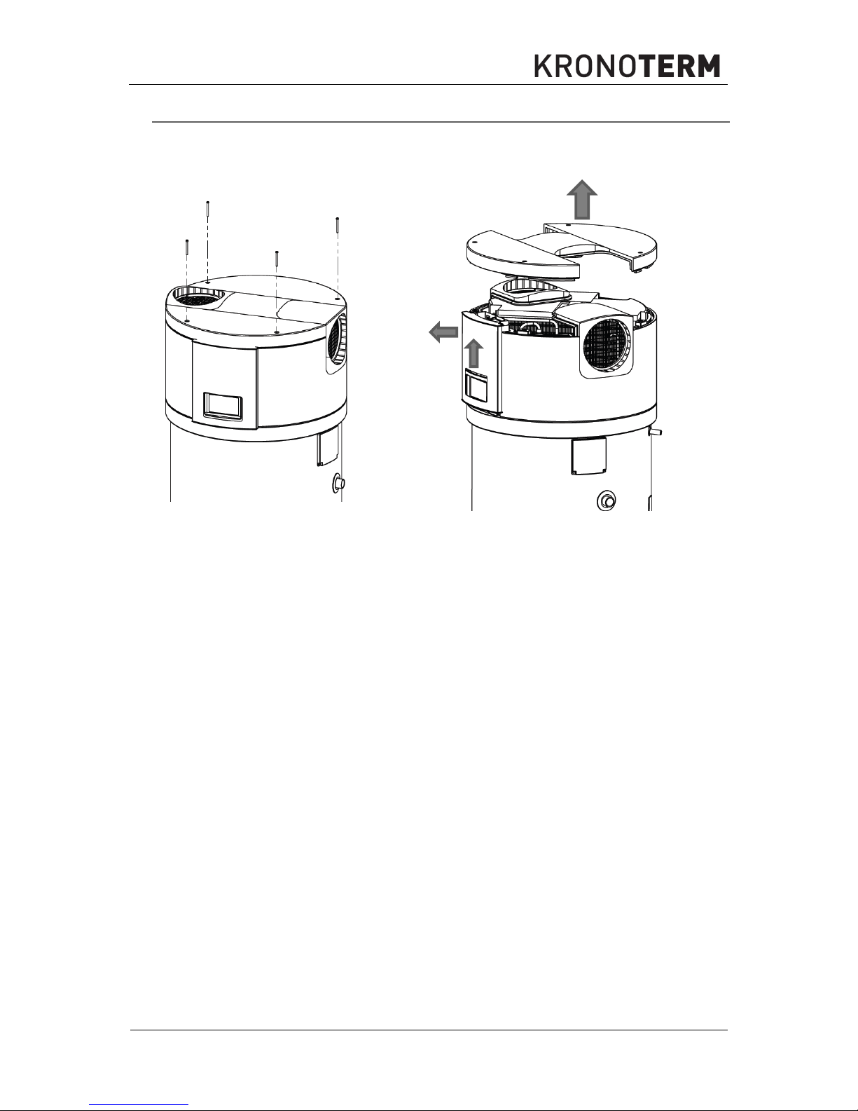
4. Cover removal – cover of electronic
To get acces to electronic components of the device it is necessary to remove the screws
(Imbus 4) on the cover of the device. Lift the cover up and remove it (1). Push the front cover
of the electronic up in the direction of the arrow (2) and pull it out towards you (3).
1
2
3

ID.: 17-16-24-3007-05
8
6.2017
5. Electrical wiring diagram
1
Compressor - generator
9
Relay panel
2
Fan
10 Display
3
Compressor capacitor
11 Temperature probe NTC - evaporator
4
Pressure switch
12 Optitronic keyboard
5
Temperature probe NTC - water
13 Safety thermostat
6
Connecting clips for regulating fan speed 14 Electrical clip
7
Connecting clip for the supply cable
15 Standard supply cable with plug
8
Connectors for the external signal
16 Electric heater

ID.: 17-16-24-3007-05
9
6.2017
Picture 1: El. Electrical wiring diagram WP2 LF-202S and WP2 LF-302S

ID.: 17-16-24-3007-05
10
6.2017
6. Technical data
Product:
Device for heating DHW with guided air
Model:
WP2 LF
-
202S
WP2 LF
-
302S
Thermal power:
W
1850 (3350)*
Electrical power:
W
440 (1940 )*
Max. electrical power:
W
560 (65 °C) (2060)*
El. heater:
W
1500
Power supply:
V
~ 230
Refrigerant:
R134a (1,2 kg) – check on data label!!!
R134a (0,9 kg) – check on data label!!!
Max. water temperature:
°C
65
Needed air flow:
m3/h
380 / 450
Protection class:
IP21
Temperature of
intake air:
°C
From +5 to +35
El. protection
A
C 16, (~ 230 V)
Max. allowed pressure in the heat
pump:
Mpa 2,3 (23 bar)
* In case the el. Heater is turned on
DESIGNATION:
WP2 LF-202S WP2 LF-302S
Volume:
l 200 270
Height:
mm 1698 2030
Diameter:
mm 635
Dimensions of the wrapped device
WxDxH:
mm 700x680x1840 700x680x2175
Joint mass:
kg 128 145
Heat exchanger surface:
m2 0.91 1.2
Highest allowed DHW pressure:
MPa 1,0 (10 bar) at 95 °C
Highest allowed working pressure
in the heat exchanger:
MPa
1,0 (10 bar) at 110 °C
DHW connections:
1''
Circulation connections:
¾''

Company headquarters and production
Kronoterm d.o.o.
Trnava 5e
3303 Gomilsko
Tel.: (00386) 3 703 16 20 | Fax: (00386) 3 703 16 33 | Web-page: www.kronoterm.com |
E-mail: info@kronoterm.com | Customer support and service.: (00386) 3 703 16 26 |
E-mail.: servis@kronoterm.com
 Loading...