

Page 1

Instructions for Use and Installation
Of the Heat Pump for Heating DHW
WP2 LF-202S
WP2 LF-302S
The manual has to be handed over to the end user after installation.
ID.: 17-16-20-2976-06 / 6.2017
ENG
Page 2

ID.: 17-16-20-2976-06 | 6.2017
1
Manual for use and installation - Version 06 / Status 6.2017
Printed in Slovenia, copyright: Kronoterm d.o.o.
This document is copyrighted. Any use outside the provisions of the copyright law without the
permission of Kronoterm d.o.o. is illegal and punishable by law. All previous versions of this
document are void. We reserve the right to make changes and mistakes in print.
Page 3

ID.: 17-16-20-2976-06 | 6.2017
2
1 Index
1 Index 2
2 Important information 4
2.1 Symbols 4
2.2 General warnings and instructions 4
2.3 Safety warnings and instructions 5
2.4 Obligations of the manufacturer 8
2.5 Obligations of the installer during installation 8
2.6 Customer support and service 8
2.7 Obligations of the user 8
2.8 Factory testing 9
2.9 Storage 9
2.10 Transport 9
2.11 Delivery package 10
3 Technical description 10
3.1 General 10
3.2 Components 11
3.3 Operating principle 13
4 The position of connections and dimensions 14
5 Installation of the device 15
5.1 Minimal clearance from the device 16
5.2 Levelling of the device 17
5.3 Hydraulic connection 17
5.4 Installation of air ducts. 19
5.5 Connection for water condensate 21
5.6 Connecting the pipe heat conductor 22
5.7 Installation of the temperature sensor for the external controller 25
5.8 Electrical connection 26
5.8.1 The electrical connection of the additional heat source and external switch 26
6 Commissioning of the device 27
6.1 Filling the device with water 27
6.2 Inspections before commissioning 27
6.3 Connecting the device to the electrical supply 28
6.4 Commissioning of the device 28
7 Controller 29
7.1 Controls 29
7.2 The program and parameters 30
7.3 Settings for programmes and parameters 31
7.3.1 Setting the water temperature 31
7.3.2 Switching between various operation programmes 31
7.3.3 Display and settings of parameters 31
7.3.4 Programme “Antifreeze” P.0 31
7.3.5 Programme “Normal” P.1 31
7.3.6 Programme “Res. Source” P.3 31
7.3.7 Programme “Automatic” P.5 32
7.3.8 Programme “Photovoltaic-PV” P.6 32
7.3.9 Programme “External signal” P.7 32
7.3.10 Parallel operation of the device’s generator and electric heater (only automatic
programmes P.5, P.6 and P.7): 32
7.3.11 Programme “Overheating-antilegionella” 33
7.3.12 Programme “Quick heating” of water 33
8 Warnings and errors 34
8.1 Warnings 34
Page 4

ID.: 17-16-20-2976-06 | 6.2017
3
8.2 Errors 34
9 Disposal 35
10 Care and maintenance 35
11 Disturbances in the operation 35
12 Electrical wiring diagram 35
13 Technical data 37
14 Legend of data label 38
Page 5

ID.: 17-16-20-2976-06 | 6.2017
4
2 Important information
The manual describes the process of installation and maintenance of the device. The
installation and maintenance can only be performed by qualified personnel. Read the manual
carefully before the installation, this way you will be informed about the intended use,
functionality and process of handling the device.
The manual has to be handed over to the end user after installation.
In case the product shall be given to a third person for use, the manual has to be
handed over to them as well.
Definitions:
An informed person is a person who reads this manual.
A qualified person has a certificate of expert qualifications.
The authorised technician is trained and authorised by the manufacturer to perform
maintenance and servicing of the device.
The user uses the device according to its use.
The installer is a person professionally trained for performing hardware and/or electro-
installation work and mounting of the device.
Incorrect use of the device can lead to damage of the device, property or injury to the user.
For limiting risks, the important information in this manual is highlighted with symbols.
2.1 Symbols
Various levels of danger can occur while performing installation, maintenance and use.
Warnings in the manual will guide you to properly and safely handle the device by avoiding
eventual dangers and ensure correct operation of the device.
These symbols mark various risks for the user or the device.
DANGER: Risk of situations which can lead to serious physical injuries.
WARNING: Risk of situations which can lead to minor physical injuries.
CAUTION: Risk of situations which can lead to damage or malfunction of the
device.
This symbol marks information for the user.
NOTE: A notice which holds important information regarding the device,
requirements and the manufacturer.
2.2 General warnings and instructions
NOTE
Read the instructions for use and installation before installation.
NOTE
Any remaking or replacement of original components of the device eliminates
the manufacturer’s guarantee for safe and functional operation. In the case of
undesignated and incorrect use of the device, the manufacturer is not
responsible for the consequences and will not acknowledge claims for
damages in these cases. The user is solely responsible for injuries and
damages on the device itself or on other objects resulting from undesignated
and incorrect use of the device.
Page 6

ID.: 17-16-20-2976-06 | 6.2017
5
NOTE
The installation of the device has to be performed in accordance with the
manual; otherwise the manufacturer does not acknowledge the warranty.
NOTE
It is necessary to consider all technical data and instructions in this manual
as well as all warnings and notes during planning, design, installation and use
of the device.
DANGER
Failure to comply with the manual and good practise while connecting the
device to the power supply can lead to serious injury or death.
WARNING
This device is intended for home use. Use of the device in hotels, stores,
farms, light industry and other public buildings is permitted to experts or
specially trained staff.
WARNING
Connecting the device to the power source can only be performed by a
qualified installer.
2.3 Safety warnings and instructions
WARNING
The device cannot be installed on a location where air is polluted with toxic
agents which could damage the device (stables, warehouses with dangerous
substances, outdoors, etc.)
WARNING
The inlet pipe of the device has to be fitted with a safety valve with a nominal
pressure of 0.6 MPa (6 bar) which prevents pressure raising in the water
heater above the nominal pressure.
WARNING
Transportation of the device is allowed in upright position. In case the device
is laid on the side, it is necessary to consider the instructions on the package
or in this manual.
WARNING
The buffer tank for DHW is intended for storing drinking water, this is why the
water has to be in accordance with the national regulations on drinking water
in force; otherwise, damage to the device and a termination of the warranty
can arise.
WARNING
If there is no water in the buffer tank for DHW, the device must not be in
operation.
Page 7

ID.: 17-16-20-2976-06 | 6.2017
6
WARNING
The connecting cable has a standard plug suitable for a standard socket (16
A; 230 V ac). This socket has to have its own power supply directly from the
main electrical cabinet. Other devices must not be connected to the same
line.
WARNING
The water from the device is emptied through the inlet pipe of the DHW buffer
tank. For this reason, it is advisable to install a special link or discharge valve
between the safety valve and the inlet pipe.
WARNING
For ensuring proper functioning of the safety valve, the valve has to be
checked regularly. Clean the lime scale if necessary and make sure the safety
valve is not blocked.
WARNING
Water can drip from the drainage pipe of the overflow, the pipe must be
subjected to outdoor air. If you fit the valve with a pipe, it must be facing
downward so the water inside cannot freeze.
WARNING
It is prohibited to play with the device. Children are not allowed to clean the
device without supervision.
WARNING
The device can be operated independently only by persons who are familiar
with the safe operation of the device and understand possible hazards of its
operation. Children older than 8 and people with reduced physical and mental
capacities and lacking experience and knowledge can only operate the device
under the supervision of an informed person.
WARNING
It is prohibited to move, shift, clean and service the device while in operation.
WARNING
Children are not allowed to clean the device and perform maintenance without
supervision.
WARNING
Before installation and any further adjustments to the device, it is necessary
to consider the instructions for safe use and maintenance.
WARNING
Installation has to be performed in accordance with regulations and
instructions of the manufacturer. It has to be performed by a professionally
trained person.
Page 8
ID.: 17-16-20-2976-06 | 6.2017
7
WARNING
The device must not be obstructed, objects must not be laid up against it.
Free access to the device must be provided at all time. If during the operation
of the device the water temperature exceeds 85 °C, the service department
has to be notified.
WARNING
It has to be made sure that the device does not endanger anybody. Access
to the device has to be denied to children and persons who are not informed
about the operation of the device.
WARNING
The device must not be placed in a room where it cannot be removed. Later
walling or setting up of other obstacles next to the device is forbidden.
WARNING
The servicing and maintenance of the device can only be performed by a
person authorised by the manufacturer. In case of a malfunction, first contact
the installer who installed the device.
WARNING
The device must never be cleaned with cleaning agents containing sand,
soda, acid or chlorides because these might damage the surface of the
device.
WARNING
The device contains the coolant R134a, which is classified as a greenhouse
gas according to the Kyoto protocol. This is why operating the device is only
allowed to persons authorised for working with the coolant as defined by the
national legislation in force. While performing works on the device, it is
necessary to prevent the coolant to leak into the atmosphere.
DANGER
Connecting the devices power cable must be performed by a qualified
electrician. During the procedure the device must not be live. The cord has to
be accessible and the socket must be of such type which enables the cord to
be pulled out in a simple manner.
CAUTION
To avoid danger, a damaged power cable can only be replaced by the
manufacturer or an authorised installer.
Page 9

ID.: 17-16-20-2976-06 | 6.2017
8
2.4 Obligations of the manufacturer
The manufacturer guarantees that the device is in accordance with current European directives
and standards. The device is marked with the mark CE and it has all the necessary
documentation.
We reserve the right to make changes to the manual without prior notice.
As manufacturer, we do not take responsibility for the consequences in the following cases:
Non-compliance with the manual for the installation of the device.
Non-compliance with the manual for the device.
Wrong and/or inadequate maintenance of the device.
2.5 Obligations of the installer during installation
The installer is responsible for installing and commissioning the device in accordance with the
following requirements:
To thoroughly study the instructions for use and installation accompanying the device
before installation.
To install the device in accordance with the instructions and national legislation, policies
and standards in force.
To perform the first commission and eliminate all eventual irregularities found during
commission.
To train the user for operating the device and settings.
To alert the user to regularly maintain the device for keeping the device functioning
properly throughout its entire lifespan.
To instruct the user about the operation of the whole system.
To give the user all the documentation accompanying the device.
2.6 Customer support and service
The manufacturer of the device provides customer support and service during the warranty
period.
When filing a service claim, provide the following information:
The precise product code.
Serial number.
Year of manufacture.
All needed information is provided on the label printed on the device.
NOTE
In case of any change or replacement of original parts, forced or incorrect use of
the device, the warranty is terminated. Eventual costs arising from the service
procedure are fully covered by the user.
During the warranty period service and maintenance can only be performed by the
manufacturer or authorised service provider. Otherwise, the warranty is
terminated.
2.7 Obligations of the user
The user must ensure uninterrupted and efficient operation of the device by considering the
following instructions:
Thoroughly study the instructions for installation and use accompanying the device.
Installation and commissioning of the device have to be performed by a qualified and
authorised person.
Allow the authorised contractor for commissions or ask him to thoroughly explain the
functioning and how to operate the device.
Page 10

ID.: 17-16-20-2976-06 | 6.2017
9
Ensure regular inspections and maintenance of the device by the authorised
maintenance worker.
These instructions for installation and use must be kept in a suitable dry place close to
the device.
2.8 Factory testing
For ensuring the high quality standard, every device is tested in production for the following:
Tightness of the cooling cycle.
Water-tightness.
Air-tightness.
Electrical safety.
Functionality.
2.9 Storage
The device has to be stored in a dry and clean place. The allowed storing temperature is
between 10 °C and 45 °C, for a short period (up to 24h) also up to 55 °C.
2.10 Transport
The device packed in a cardboard packaging can be transported in the vertical or horizontal
position. In a horizontal position, the device can only be tilted to the right (seen from the front
side) as defined on the cardboard packaging.
CAUTION
Horizontal transport in the cardboard packaging is allowed only up to a distance of
150 km.
If the device is transported without a cardboard packaging, it has to be properly protected.
When transporting the device in horizontal position, the device can be tilted to the side, as
marked on the picture:
Page 11

ID.: 17-16-20-2976-06 | 6.2017
10
The pump is not allowed to be tilted forward or backward for more than 30 °.
CAUTION
Horizontal transport without packaging is allowed only during final positioning in
the building and not during transport from supplier to customer.
CAUTION
While moving the device, it has to be disconnected from the power supply.
WARNING
The device contains shock-sensitive components, care has to be taken not to
cause impacts during transferring or that the pump does not fall.
WARNING
The mass of the device exceeds the allowed mass for one person to lift. All
responsibility for eventual injuries or damage to property or the device is taken by
the user.
CAUTION
The device can only be transported in a horizontal position if it is placed on its right
side (in the direction where the connections are visible). Placing the device in other
horizontal positions is strictly prohibited.
2.11 Delivery package
Delivery package:
1. Heat pump
2. Pipe for water condensation drainage.
3. Instructions for Use and Installation
3 Technical description
3.1 General
The heat pump is a device intended for efficient heating of DHW in residential or small business
spaces. In heating the DHW, the device simultaneously cools the room where the air is
returned to and heat for heating water has been taken from. The device heats the DHW as
well as cools the room. Here we have to stress that it will only cool the room when there will
be a simultaneous need for heating DHW.
NOTE
For maximal efficiency and economical use, we advise to use air from rooms where
waste heat is generated for heating DHW (boiler rooms, laundries, kitchens,
basements, pantries ...)
Page 12

ID.: 17-16-20-2976-06 | 6.2017
11
3.2 Components
B
D
A
C
F
E
G
H
I
M
J
K
A Air intake Φ180
B Air outlet Φ180
C Device generator casing
D Fan
E Compressor
F Evaporator
G Controller
H Buffer tank for DHW (boiler)
I Anti-corrosion anode
J
Heat exchaanger (heating
water)
K Condenser
M Electric heater
The device consists of the device generator (compressor, evaporator, fan ...) and buffer tank
for DHW. The casing of the generator is made of expanded polypropylene (EPP) which also
functions as heat and noise insulation for the generator. The casing has two connections for
air channels which offer remote air intake and outlet from other rooms or the surroundings via
pipe connection. The DHW buffer tank has a built-in heat exchanger which can be connected
to an external fossil fuel, biomass or solar collector DHW.
Buffer tank for DHW
The buffer tank for DHW is an enamelled container insulated with polyurethane and protected
with sheet metal. The buffer tank for DHW is a standard fitted water heat exchanger for
connection to the DHW when choosing an alternative or additional heat source. The interior of
Page 13

ID.: 17-16-20-2976-06 | 6.2017
12
the buffer thank for DHW has a built-in anti-corrosion anode (Mg) which prevents rusting of the
buffer tank in the event of damage to the enamel.
Electric heater
The device is standard fitted with an electrical heater of 1.5 kW which serves as additional or
backup heat source.
Antifreeze sensor
The device’s controller has an air temperature sensor which performs a safety shut-down of
the device for a minimum of 30 minutes in case the temperature of the air flowing through the
evaporator of the device is lower than +5 °C.
Safety thermostat
The device has a safety thermostat which is set to 90 °C. This means if the water temperature
inside the buffer tank for DHW exceeds this limit, the electrical connection to the device will be
terminated and the device will cease to operate. You have to contact the authorised installer
for a renewed commissioning of the device to check and eliminate the cause of the safety shut
down of the device.
CAUTION
When heating with DHW or solar collectors, the water in the buffer tank can be
heated above 95 °C which will trigger a shut-down of the safety thermostat. In this
case the thermostat has to be manually reset. For a renewed commissioning of
the thermostat it is necessary to call the authorised installer.
Controlling the water temperature in the buffer tank for DHW
An advanced controller with the label OPTITRONIC is responsible for controlling water heating
to the desired temperature.
Depending on the set desired temperature of water, the controller turns the operation of the
compressor and fan on or off; in certain cases it also turns on or off the electric heater or
circulation pump of the DHW. The maximal temperature setting for heating water is 65 °C. If
the water in the buffer tank exceeds 90 °C, the controller turns off all heat sources connected
to it.
The minimal water temperature in the buffer tank for DHW is 7 °C.
High-pressure protection for the cooling system
To prevent high pressure in the cooling system and associated damage the device has a builtin high-pressure safety switch which turns off the device in case of high pressure.
Operating conditions
The temperature of the surroundings in normal operation must be between +5 °C and +35 °C.
The air must be clean, the relative moisture at +35 °C must not exceed 50 %. At lower air
temperatures the relative moisture can be higher. With devices installed at high altitudes, lower
air pressure can cause degraded performance of the device.
Page 14

ID.: 17-16-20-2976-06 | 6.2017
13
3.3 Operating principle
5
6
4
8
3
10
1
2
9
1 Compressor 6 Fan
2 Condenser 8 Temperature sensor for the expansion valve
3 Dehydrator 9 Electric heater
4 Expansion valve 10 Buffer tank for DHW (boiler)
5 Evaporator
The cooling system of the device is a closed circuit system with the heat exchange liquid
R134A. At lower pressure and temperature (i.e. 10 °C) the coolant is evaporated in the
evaporator and thus removes heat from the air. Afterwards, the compressor compresses
the coolant to a higher pressure, this results in the raising of the coolant temperature to a
level higher than the water temperature in the buffer tank for DHW. The coolant then
releases the heat in the condenser into the water and condenses as a result. With the
expansion of the coolant the pressure and temperature in the coolant fall to their initial
level, completing the circular process. This process is repeated throughout the device’s
operation.
Page 15

ID.: 17-16-20-2976-06 | 6.2017
14
4 The position of connections and dimensions
WP2 LF
-
202S WP2 LF
-
302S
A [mm]
85 85
B [mm]
263 263
C [mm]
638 728
D [mm]
800 983
E [mm]
1057 1390
F [mm]
1387 1720
G [mm]
1700 2030
H [mm]
840 840
I [mm]
1597 1927
J [mm]
1252 1584
K [mm]
1790 2105
1
Cold water connection G1”
2
Heat exchanger connection - return G1”
3
Heat exchanger connection - supply pipe G1”
4
Circulation connection G3/4”
5
Hot water connection G1”
6
Screen
7
Flange
8 Air connection - Φ180
9 Connection for water condensate drainage - Φ16
10
Heat exchanger temperature sensor duct
11
Electrical connections
Page 16

ID.: 17-16-20-2976-06 | 6.2017
15
5 Installation of the device
The lowest ceiling height in the room with the heat pump WP2 LF202S is 1900 mm; with the
heat pump WP2 LF-302S it is 2200 mm. The device is designed to take the heat from the
surrounding air or suck the air through air channels and blow it into the adjoining rooms or
surroundings. The device can be installed in the following ways:
Picture 1: Drawing air from the adjoining room and releasing it back into it (i.e. drying clothes).
Picture 2: Drawing air from the same room and releasing it back into it.
Picture 3: Drawing air from the adjoining room and releasing it back into it (i.e. pantry cooling).
Picture 4: Drawing air from the adjoining room and releasing it into the surroundings.
Page 17

ID.: 17-16-20-2976-06 | 6.2017
16
The most common installation of the device enables it to draw air from rooms with a lot of
excess heat. A part of heat is drawn from this air and then released into the surroundings. The
air in kitchens, washing or sanitary rooms often has unpleasant odours, this is why it is released
into the surroundings. Here we must be careful to equalise the air flows and pressures in the
rooms; this has to be taken care of by the responsible ventilation design engineer.
CAUTION
The device cannot be installed on a location where air is polluted with toxic agents
which could damage the device (stables, warehouses with dangerous substances,
outdoors ...)
5.1 Minimal clearance from the device
The device can be installed in a room with installed air ducts or without them. This influences
the minimal clearance of the device from the walls; these depend on the direction of air intake
and outlet (chapter 5.4).
D
B
A
C
A
C
Picture 5: Minimal clearance from the walls
Air intake
Φ180
Air outlet
Φ180
A [mm] B [mm] C [mm] D [mm]
Without
bend
With bend
on the
outlet
Without
bend
With bend
on the
outlet
On the
side
On the
side
1000 250 90 90 200 / 250** 70
On the
side
Above 60 60 1000 250 200 / 250** 70
Above On the
side
1000 250 200 200 200 70
Above Above 60 60 /* 250 200 70
*If both air ducts are turned upwards, it is necessary to prevent the outlet and intake air to mix; this could lead to a
so-called “short-circuit” between outlet and intake air which significantly lowers the device’s performance. This is
why we recommend adding a bend on the outlet air connection and turn the outlet air away from the intake air.
**If the air connection of the intake air has a bend.
Page 18

ID.: 17-16-20-2976-06 | 6.2017
17
At least 1 m of space must be provided in front of the device for control and servicing purposes.
If the air is drawn from the room device is located, the volume of the room must be at least
30 m3.
5.2 Levelling of the device
CAUTION
During operation, the device has to be placed in a vertical position to prevent
eventual saturation of the water condensate.
Picture 6: Levelling of the device
The device has a level bottom. For correct installation, the device requires a level and solid
surface. We recommend making a pedestal for the device (1-2 cm high) and thus preventing
eventual water saturating the insulation of the buffer tank for DHW.
The surface on which the device is laid must be level. Thus we ensure the device is levelled
on all sides. Otherwise, unwanted overflow of condensate can occur in the collecting vessel.
5.3 Hydraulic connection
The hydraulic connection has to be installed in accordance with the national and local
regulations for connecting buffer tanks for DHW in force. The room the device is installed in
must have a drain on the floor below the level of the device in case of water leakage. The
following picture shows the correct hydraulic connection of the device.
If the heat conductor (for heated water) in the buffer tank for DHW will not be used for heating
water, it must be filled with antifreeze liquid to prevent corrosion in the conductor. Close the
filled conductor only on the bottom side (equalisation of pressure because of temperature
differences).
Page 19

ID.: 17-16-20-2976-06 | 6.2017
18
CAUTION
Because different materials are used on the pipe installation, all connections on the
device (cold and hot water, circulation, heat conductor) have to be in galvanic
isolation; otherwise corrosion of connections can occur on the inner side of the
buffer tank for DHW. We recommend placing galvanic isolators made of red brass
the length of at least twice the diameter of the pipe on the connections.
CAUTION
The buffer tank for DHW is intended for storing drinking water, this is why the water
has to be in accordance with the national regulations on drinking water in force;
otherwise, damage to the device and a termination of the warranty can arise.
1 Closing valve 5 Expansion tank
2 Pressure reducing valve 6 Charging pipe
3 Check valve 7 Circulation pump
4 Safety valve 8 Device generator
1 2 3 1
4 5
6
1
7
3
1
1
8
Picture 7: Connecting the device to the water supply
Dimensions of the expansion tank:
Adjusting the safety valve [bar]
6
System pressure [bar]
3.0 3.5 4.0
Volume of buffer tank for DHW [L]
Expansion tank [L]*
200
5 8 12
270
8 8 12
* The actual size of the expansion tank has to be defined by the installer/design engineer
according to the extent of the system the device will be installed in.
CAUTION
When installing the device, an expansion tank has to be installed as well.
CAUTION
The inlet pipe of the device has to be fitted with a safety valve with a nominal
pressure of 0.6 MPa (6 bar) which prevents pressure raising in the buffer tank for
DHW more than 0.1 MPa (1 bar) above the nominal pressure.
Page 20

ID.: 17-16-20-2976-06 | 6.2017
19
CAUTION
For normal operation of the expansion tank, it is necessary to perform proper
adjustments of the tank’s working pressure. The pressure is adjusted according to
the pressure of the water supply. The settings have to be checked every 6 months.
5.4 Installation of air ducts.
The device has connections for air ducts installed on the casing. The diameter of the
connection hole is φ180 mm which enables the connection of standard air ducts φ150 mm
(internal diameter) from our sales catalogue (hoses Isopipe or Centrotherm); you can also use
sewage pipes with the diameter of φ160 mm (internal diameter). In case of using pipes without
insulation, the pipes have to be insulated to prevent water condensation on the surface of the
pipe.
The construction of the casing enables turning the air connections upwards and sideways
enabling changing the direction of air intake and outlet. This way the device can be optimally
placed into the room (minimal clearance from the walls), the number of elements and air ducts
which cause additional air pressure drops and lessen the characteristics of the device can be
reduced.
To change the direction of air duct connections, it is necessary to remove the screws on the
cover of the device and remove the cover (
picture 8). After removing the cover, the air ducts can be pulled out upwards and turned with
the opening facing upwards or sideways.
Picture 8: Changing the direction of air duct connections
The openings of the air duct connections are turned to the side by default. In case of a
malfunction near the air connection it is recommended to turn the connection and thus enable
easier air flow through the device.
Imbus 4
Screwing torque max. 0.5
2
1
2
3
3
Page 21

ID.: 17-16-20-2976-06 | 6.2017
20
On the air outlet side it is necessary to enable unobstructed air flow at least 1 m behind the air
connection. On the side of the ceiling it is necessary to enable at least 20 cm of unobstructed
air flow.
In case air ducts are used, it has to be considered that the air pipes and every additional bend
represent additional air resistance and lesser capacity of the device. The table below shows
the maximal allowed lengths of air ducts.
Maximal length of air ducts m
Internal diameter 150 mm: 10
Internal diameter 160 mm: 15
Internal diameter 200 mm: 25
When determining the end length of air ducts, the equivalent length of elements such as bends,
reducers, ... has to be taken into account.
Accessories Equivalent length in m
Bend 90° (Φ 160 mm): 3
Bend 90° (Φ 200 mm): 2
Reducer Φ 200xΦ 160: 1
External grill (Φ 160 mm): 2
NOTE
The device must be installed in a manner which prevents mixing of the air on the
intake and outlet. If this is not possible and the pump is used for drawing and
releasing air in the same room (picture 2), direct mixing of intake and outlet air
must be prevented.
Page 22

ID.: 17-16-20-2976-06 | 6.2017
21
5.5 Connection for water condensate
By extracting heat from the air, water condensate starts forming on the surface of the
evaporator. The intensity of moisture extraction from the air and the quantity of water
condensate change depending on the temperature and relative moisture. In some cases no
water is extracted from the air, in other cases more than 10 litres of water condensate can be
extracted.
Connecting the pipe for water condensate drainage to
the device.
The syphon for preventing the intake of unpleasant
odours from the drain.
The pipe for water condensate drainage has to be routed in a manner which enables the water
free flow at all time. Connect the drainage pipe with the drain. If this is not possible, a collecting
vessel has to be installed which has to be emptied on a regular basis.
NOTE
When installing the drain pipe for water condensate, pay attention that the pipe
points downwards at all times. A siphon has to be installed on the pipe with a water
column of at least 5 cm. This prevents the intake of unpleasant odours from the
drains.
Page 23

ID.: 17-16-20-2976-06 | 6.2017
22
5.6 Connecting the pipe heat conductor
The water in the buffer tank for DHW can be heated by the device’s generator - the heat pump
(primary source) and/or various external heat sources. When filling the device, follow the
instructions outlined below.
CAUTION
Because different materials are used on the pipe installation, all connections on the
device (cold and hot water, circulation, heat conductor) have to be in galvanic
isolation; otherwise corrosion can occur on the inner side of the buffer tank. We
recommend placing galvanic isolators made of red brass the length of at least twice
the diameter of the pipe on the connections.
CAUTION
The water used for heating DHW via the built-in heat exchanger in the buffer tank for
DHW has to be in accordance with the requirements of standard VDI 2035. The
heating system has to be filled with soft water which has been added anti-corrosion
and antibacterial agents for preventing corrosion. Before filling the heating system
has to be cleaned of all impurities.
The heating system has to be thoroughly vented. Air leaking into the system,
including diffusion air, has to be prevented.
Maximal allowed content of individual substances in the heating water and the influence of
these on the heat exchanger are presented in the table below. It is not allowed to use heating
water which contains any substance in concentrations which cause corrosion in the heating
system (influence “-”). It is also not allowed to use heating water which contains two or more
substances in concentrations which could cause corrosion in the heating system (influence
“0”).
Page 24

ID.: 17-16-20-2976-06 | 6.2017
23
TYPE OF PRESENT SUBSTANCE
UNIT CONCENTRATION
INFLUENCE TO THE HEAT CONDUCTOR
Organic sediment
mg/L
0
Ammonia (NH3) mg/L
< 2
1 - 20
> 20
+
0
-
Chloride mg/L
< 300
> 300
+
0
Allowed water hardness
°dH
5–10
Electrical conductivity µS/cm
< 10
10-500
> 500
0
+
-
Iron (Fe) removed mg/L
< 0.2
> 0.2
+
0
Free carbonic acid mg/L
< 5
5-20
> 20
+
0
-
Manganese (Mn) removed mg/L
< 0.1
> 0.1
+
0
Nitrates (NO3) removed mg/L
< 100
> 100
+
0
pH value mg/L
< 7.5
7.5-9
> 9
0
+
0
Oxygen mg/L
< 2
> 2
+
0
Hydrogen sulphide (H2S) mg/L
< 0.05
> 0.05
+
-
HCO3- / SO
4
2
- mg/L
> 1
< 1
+
0
Hydrogen carbonate mg/L
< 70
70-300
> 300
0
+
0
Aluminium (Al) removed mg/L
< 0.2
> 0.2
+
0
Sulphates mg/L
< 70
70-300
> 300
+
0
-
Sulphite (SO
3
) mg/L
< 1 +
Chlorine (gas) (Cl2) mg/L
< 1
1-5
> 5
+
0
-
Table: Influences of various aggressive substances in heating water on the durability of the
buffer tank for DHW (+ = no influence, 0 = danger of corrosion, - = corrosion, use not permitted).
CAUTION
The heating system has to be filled with water with the hardness between 5 °dH
and 10 °dH. Malfunctions of the device because of water hardness are not covered
by the warranty.
CAUTION
Drinking water quality must be in accordance with the Decree of Drinking
Water (Ur.l. RS, No.19/04, 35/04, 26/06, 92/06, 25/09). This decree is in
accordance with the Decree of the Council 98/83/ES.
CAUTION
For proper functioning of the active corrosive protection the buffer tank for DHW
has to be filled with water with the conductivity of at least 200 µS.
Page 25

ID.: 17-16-20-2976-06 | 6.2017
24
Below there are some possible wiring diagrams for connecting the external source for heating
DHW.
1 Closing valve 7 Circulation pump
2 Pressure reducing valve 8 Device generator
3 Check valve 9 DHW
4 Safety valve 10 Heating water buffer tank
5 Expansion tank 11 Solar energy collector
6 Charging pipe dT Differential thermostat
1 2 3 1
456
3 1 1
7
1
45
1
7
9
3
1
1
8
Picture 9: Device in combination with the DHW
1 2 3 1
1
3
1
7
4 5 6
1
11
3
1
1
7
8
Picture 10: Device in combination with collectors of solar energy
Page 26

ID.: 17-16-20-2976-06 | 6.2017
25
1 2 3 1
4 5 6
3
1 1
7
1
3
1
1
7
4 5
11
1 1
10
8
Picture 11: Device in combination with buffer tank for DHW
5.7 Installation of the temperature sensor for the external controller
In case of using a controller for the additional source, install the temperature sensor for the
external controller in the appropriate duct on the right side of the device under the black plastic
cover, as indicated on the picture.
Picture 12: The duct for the temperature sensor on the right side of the device
Page 27

ID.: 17-16-20-2976-06 | 6.2017
26
NOTE
For ensuring safe and efficient operation of the additional heat source for DHW
(DHW, solar collectors) the controller for the external source has to be set to
maximum water temperature of 85 °C. The recommended temperature setting is
65 °C or lower.
The highest allowed water temperature in the heat exchanger is 110 °C.
5.8 Electrical connection
The hydraulic connection of the device to the water supply is followed by the electrical
connection. For connecting the device to the electricity the plug of the connecting cable has to
be plugged into a standard socket and the device will start up automatically. The
commissioning procedure is described in chapter 6.4.
CAUTION
The device has no additional switch for commissioning, it will turn on immediately
after connecting it to the electricity grid. Before turning on the device it is necessary
to follow the instructions in chapter 6.4.
CAUTION
The connecting cable has a standard plug suitable for a standard socket (16 A;
230 V ac). This socket has to have its own power supply directly from the main
electrical cabinet. Other devices must not be connected to the same line.
DANGER
The device must be connected to the electricity supply where the RCD (FID) switch
of type A is installed.
If you want to connect an alternative heating source or an external input source to the device,
it is necessary to follow the instructions in chapter 5.8.1.
5.8.1 The electrical connection of the additional heat source and external switch
All the electrical connections are carried out on the right side of the device. The connection
clips are located under the plastic cover. The connecting cable is connected to the leftmost
connection clip.
Picture 13: The position of connection clips on the right side of the device
The connection clips (
picture 14
) are intended for changing the speed of the fan and connecting
the external switch.
Page 28

ID.: 17-16-20-2976-06 | 6.2017
27
Picture 14: The connection clips for adjusting the speed of the fan and connecting the external
signal switch
The fan of the device has two different speeds. Changing the speed can be performed by
different connections of the bridge between clips A1, A2 and A3.
• The fan operates with low speed (v1)
Connect the bridge in the position between connection clips A1 and A2. This will make the
fan operate with low speed.
• The fan operates with high speed (v2)
The factory setting of the bridge is the position between connection clips A1 and A3. This
means the fan will operate with high speed.
By triggering the voltage-free external switch which you connect to the connection clips B1 and
B2, the device enables automatic change of water heating programme. In case of lower rate
of electricity or using photovoltaic energy, the device automatically switches to the operating
programme triggered by the PV signal which enables saving electricity.
6 Commissioning of the device
6.1 Filling the device with water
After an expert has connected the device to the water supply, the system has to be filled with
water and thoroughly vented. This is performed by opening all water taps in the residence.
When water flows uninterrupted from all taps, the system is thoroughly vented.
CAUTION
The device’s generator must never operate without water in the buffer tank for
DHW.
6.2 Inspections before commissioning
Before commissioning, the following inspections must be performed on the device:
The buffer tank for DHW must be filled with water and thoroughly vented.
All hydraulic connections must be tightly sealed.
A suitable expansion tank and safety valve must be installed.
All safety elements must work.
CAUTION
Connection clips B1 and B2 are voltage-free, whereas clips for fan setting are live
~ 230 V.
A2 B2 A3 B1 A1
Page 29

ID.: 17-16-20-2976-06 | 6.2017
28
6.3 Connecting the device to the electrical supply
The device is equipped with a standard connection cable. Before commissioning, the plug of
the connection cable has to be plugged into the standard socket 16 A, 230 V ac.
6.4 Commissioning of the device
After connecting the electrical plug to the mains, the version of the regulator and factory
settings parameters L.1–L.7, H.0–H.9 and d.0–d.6 and their values appear on the screen after
2 seconds. 30 seconds after connecting the device to the mains, the entire system starts up
and starts heating the water in the buffer tank for DHW. The device starts operating and
operates until the set breaking temperature is reached. The breaking temperature is factory
set to 52 °C. After shut-down the operation is interrupted until the water cools for 5 °C, i.e. to
47 °C. When the water in the buffer tank for DHW reaches this temperature, the device turns
on again. The user can freely raise the set breaking temperature but no more than 55 °C
(restriction of the regulator) or freely lower it. Overheating the water to 65 °C is factory restricted
to this value and cannot be readjusted.
NOTE
The device operates with intake air from approx. +5 °C to approx. 35 °C (depending
on relative moisture).
Page 30
ID.: 17-16-20-2976-06 | 6.2017
29
7 Controller
7.1 Controls
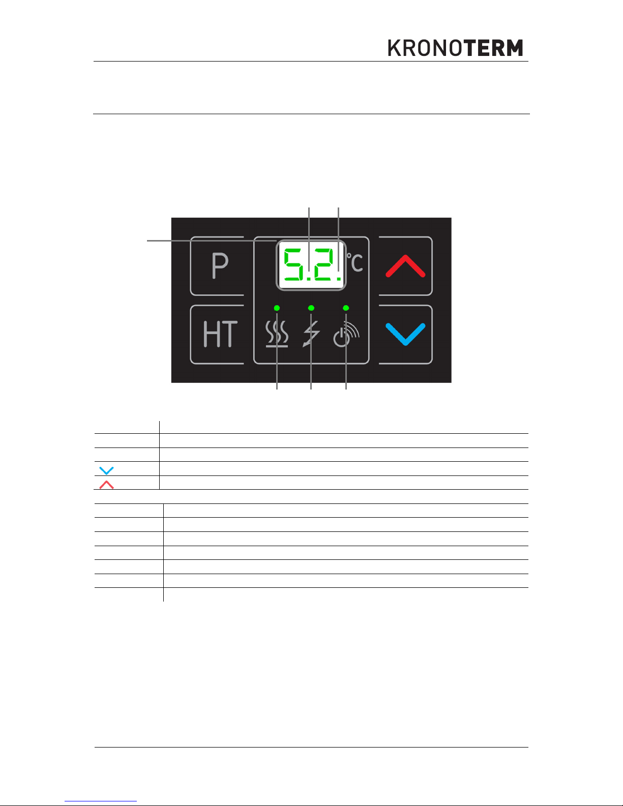
The device is operated by the use of 4 keys on the controller interface OPTITRONIC. The
controller interface has a display with a sixteen-segment display (6) which displays the current
state of the device and five device status indicators (1-5).
The controller interface OPTITRONIC on the device:
BUTTON
Description
P
Key for changing the operation mode
HT
Key for thermal disinfection (protection against legionella) and quick heating
Key for adjusting the temperature or parameter values
Key for adjusting the temperature or parameter values
INDICATOR Description
1
Indicator “1” for quick heating and thermal disinfection
2
Indicator “2” for compressor safeguard
3
Indicator “3” for compressor operation
4
Indicator “4” for electric heater operation
5
Indicator “5” for active external signal
6
Temperature and parameter display
6
1
2
3
4 5
Page 31

ID.: 17-16-20-2976-06 | 6.2017
30
7.2 The program and parameters
The controller provides setting the operation in five different programmes described below and
enables setting three different desired heating temperatures.
The “Antifreeze” programme P.0 enables the display of set temperature of the programme.
Programmes “Normal” P.1, “Res. Source”, P.0 and “Automatic” P.5 enable settings of one
value of desired temperature.
The programme “Photovoltaic” P.6 enables a different setting of the desired temperature value
set with the parameter L.6 and is activated with an active external signal.
The programme “External signal” P.7 will be activated with an active external signal and thus
enable the setting of a third desired heating temperature.
Programmes
Mark of the
programme
Name
P.0
Programme “Antifreeze”
P.1
Programme “Normal”
P.3
Programme “Res. source”
P.5
Programme “Automatic”
P.6
Programme “Photovoltaic - PV”
P.7
Programme “External signal”
NOTE
Pressing the key P for the first time checks the currently selected operating
programme. Pressing the key P in the time frame of 8 seconds switches between
different programmes.
Parameters
Parameter
mark
Description
Scope
Default
L.0
Evaporator temperature in
°C (only display)
–15–95 °C
L.1
Min. operation temp. in °C –15-30 °C [0]
L.2
Time interval of
overheating in days
- -; 1–99 days [14]
L.3
Display of active outputs
(only display)
0–5 0 – no output is active
4 – EG
5 – HP + EH
L.4
Standby 1-10 °C [5]
L.5
Automatic quick water
heating
- -; 1–50 °C [- -]
L.6
Raising the temperature
at PV
1-20 °C [5]
L.7
Standby at PV signal 1-10 °C [3]
NOTE
Water overheating in programme P.5, P.6 or P.7 is performed with the currently
active heat generator.
Page 32

ID.: 17-16-20-2976-06 | 6.2017
31
7.3 Settings for programmes and parameters
7.3.1 Setting the water temperature
Pressing the key or for the first time displays the currently set temperature, additionally
pressing the key or (in the time frame of 10 seconds) triggers its modification. If we wait
for 5 seconds, the new setting will be stored after the blinking stops.
7.3.2 Switching between various operation programmes
Switching between various operation programmes is performed by additionally pressing the
key P in the time frame of 8 seconds - this switches between available operational
programmes.
7.3.3 Display and settings of parameters
We enter the settings by pressing the key and at the same time. The parameter L.0 is
displayed. This enables us to choose the desired parameter by pressing the key or .
When the desired parameter has been chosen, we have to wait for 8 seconds, then the value
of the chosen parameter is displayed. During the display of the parameter the value of the
parameter can be changed with the key or . After the value has been chosen, we have
to wait 10 seconds to confirm the value of the parameter and the display returns to the basic
menu which displays the current water temp. in the buffer tank for DHW.
7.3.4 Programme “Antifreeze” P.0
The operation of the device is turned off, only the temperature display in the buffer tank for
DHW is active. The programme “Antifreeze” is active, it maintains the water temperature in the
buffer tank for DHW at 10 °C.
7.3.5 Programme “Normal” P.1
Basic
The device in the programme “Normal” P.1 heats the water with the device’s generator until
the set temperature is reached and until the temperature of the evaporator is above min.
operating temperature (L.1). If the air in the room cools below the set operating temperature,
the device performs a security shut-down of the device’s generator. When the air temperature
in the room is above the minimal temperature at least for 60 minutes, the device activates the
device’s generator and continues heating the water up to the set temperature. Water
overheating in the programme “Normal” P.1 is performed with the device’s generator.
Renewed heating starts when the water temperature set with the standby value (L.4) drops
below the set desired temperature of the buffer for DHW.
7.3.6 Programme “Res. Source” P.3
Basic
During the programme “Res. Source” P.3 the device heats the water with the electric heater to
the set temperature independently form the evaporator temperature.
Advanced
The electric heater (EH) is active until the set water temperature is reached.
Renewed heating starts when the water temperature set with the standby value (L.4) drops
below the set desired temperature of the buffer for DHW.
Page 33

ID.: 17-16-20-2976-06 | 6.2017
32
7.3.7 Programme “Automatic” P.5
Basic
The device operates in the programme “Automatic” P.5 and heats the water with the device’s
generator up to the set temperature. It operates inside the limited temp. zone of the evaporator.
In case the temp. of the evaporator is too low, the device automatically switches to heating
with the electric heater.
Advanced
The water is heated with the device’s generator and automatic switch to the electric heater in
case of low evaporator temperature. The device operates fully automatically with the priority
of the device’s generator operation until the set water temperature is reached. If the
temperature of the evaporator is outside the operation zone, the device automatically switches
to heating with the electric heater. In case the temperature of the evaporator drops below the
temperature set by the parameter (L.1), the electric heater turns on. Shut-down of electric
heater occurs 30 minutes after the temperature of the evaporator is raised by 3 °C.
7.3.8 Programme “Photovoltaic-PV” P.6
Basic
This programme heats the water in combination with photovoltaic panels and performs the
same as the “Automatic” P.5 programme, but in the case of an active external signal from the
inverter of the photovoltaic power plant, the device raises the water temperature in the buffer
tank for DHW for the value set with the parameter L.6.
7.3.9 Programme “External signal” P.7
Basic
The operation of the device is the same as programme “Automatic” P.5. In case of an inactive
external signal, the device is in stand-by. In case of an active external signal, the device will
heat the water up to the temperature set in the programme P.7. The temperature of heated
water can be set to a value different from the ones in programmes “Normal”, “Res. source”,
and “Automatic” and “Photovoltaic-PV”. Remote activation of the device operates only in the
presence of an external signal.
7.3.10 Parallel operation of the device’s generator and electric heater (only automatic
programmes P.5, P.6 and P.7):
Choose parameter L.1. Use key or to adjust the desired temperature for parallel
activation of the electric heater.
Approximate values for setting the parameter L.1 are given in the table.
Air temperature [°C]
Value for setting the parameter L.1
+ 10 0
+ 7 -3
+ 5 -5
+ 3 -7
NOTE
Water overheating in the programme “Res. Source” P.3 is performed with an
electrical heater. The temperature of the evaporator does not influence the
operation.
Page 34

ID.: 17-16-20-2976-06 | 6.2017
33
NOTE
The device senses the evaporator temperature and it is lower than the temperature
of the surrounding air where the device is located or the air which the device takes
in.
The electric heater will perform a parallel activation at the set temperature. Shut-down of
electric heater occurs 30 minutes after the temperature of the evaporator is raised by 3 °C
above the value set with the parameter L.1.
7.3.11 Programme “Overheating-antilegionella”
Thermal disinfection or one-time overheating of water above 60 °C is activated with the key
HT (indicator “1” is on). After the overheating finishes, the indicator “1” turns off. We can end
the overheating early by pressing the key HT again.
NOTE
The National Institute of Public Health advises water overheating once every
fourteen days.
NOTE
During the operation of the programme “Overheating-antilegionella” the indicator “1”
is on.
NOTE
In case the overheating is not successful in 12 hours, the function turns of and
continues with normal heating.
Adjusting the automatic overheating-antilegionella
Choose the parameter L.2, after a couple of seconds the set interval of overheating is displayed
(factory set to 14 days). During the display of the set value no. of days, it can be modified with
the key or (»- -« disabled or from 1 to 99 days). After setting the desired value, wait for
5 seconds, after the blinking stops the setting is saved.
NOTE
The National Institute of Public Health advises water overheating once every
fourteen days. Too frequent overheating is not advised because the energy
consumption with overheating is 1/3 higher than normal operation of the device.
7.3.12 Programme “Quick heating” of water
The programme is intended for one-time quick water heating with the device’s generator and
electric heater simultaneously in programmes “Automatic” P.5, “Photovoltaic P-V” P.6 and
“External signal” P.7.
After the temperature is reached, the programme “Quick heating” turns off and goes back into
the previous operation setting. The programme is activated manually by pressing the key HT
for approx. 10 seconds (indicator “1” blinks). After reaching the desired water temperature the
indicator turns off. We can end the quick heating early by pressing the key HT again.
Page 35

ID.: 17-16-20-2976-06 | 6.2017
34
NOTE
During the operation of quick heating the indicator “1” blinks.
NOTE
In case the heating is not successful in 12 hours, the function turns of and continues
with normal heating. Quick heating does not work in programmes “Normal” P.1 and
“Res. source”.
Setting automatic quick heating
Choose parameter L.5, after a couple of seconds the default set value displays (factory
disabled [--]). During the display of the factory set value - -, it can be modified with the key
or (»- -« disabled or from 1 to 50 °C). After setting the desired value, wait for 5 seconds,
after the blinking stops the setting is saved.
NOTE
Automatic quick heating operates in case one of the following operating
programmes is chosen: “Automatic” P.5 “Photovoltaic-PV” P.6 and “External signal”
P.7.
8 Warnings and errors
Warnings and errors are displayed on the OPTITRONIC display with a black number and signs
– –
or
– –.
.
8.1 Warnings
Mark
Reason
Solution
A1
Shut down of the device
because of low temperature of
the evaporator.
The room must be vented to raise the temperature of the
evaporator above the lower limit.
Set the shutdown temperature to the lowest value with
the parameter L.1.
A3
Shut down of the device
because of high temperature of
the evaporator.
The room must be vented to lower the temperature of the
evaporator below the upper limit.
If the temperature of the evaporator is constantly above
the upper limit, another room must be found for setting
up the device or the air ducts have to be routed into the
room with a temperature lower than the upper level.
8.2 Errors
Mark Reason
Solution
Alternately
E8
and
The sensor for DHW is not
connected.
Check whether the sensor is connected. Otherwise,
see chapter 11.
Alternately
E8
And _ _
Malfunction of the temperature
sensor for DHW.
First, turn off the device and reconnect it to the mains.
Check the connection and the cable of the cable. If the
malfunction persists, see chapter 11.
Alternately
E9
And ¯ ¯
The sensor of the evaporator is
not connected.
Check whether the sensor is connected. Otherwise,
see chapter 11.
Alternately
E9
and _ _
Evaporator sensor malfunction.
First, turn off the heat pump and reconnect it to the
mains. Check the connection and the cable of the
cable. If the malfunction persists, see chapter 11.
Page 36

ID.: 17-16-20-2976-06 | 6.2017
35
9 Disposal
The device has a lifetime of at least 8 years if the instructions for safe use and maintenance
are considered. Individual components have different lifetimes, this is why they have to be
replaced with new parts in cases of possible malfunctions, wear and mechanical damage.
Replacement can be performed only by using technically adequate or original replacement
parts.
At the end of the device’s lifespan the entire device must be taken to the depot for electronic
equipment according to the classification of wastes. The device falls into the category of large
household wastes.
10 Care and maintenance
For reliable and efficient operation of the device it has to be regularly cared for and maintained.
CAUTION
The device may only be cleaned with water or damp cloth. The use of detergents,
solvents and / or cleaners containing tensides is prohibited and can lead to
damage to the device.
Perform regular checks of the device’s operation, be sure to inspect:
The operation of the safety valve on the water supply installation.
Cleanliness of the surface of the evaporator.
If the surface of the evaporator is dirty, order cleaning with the authorised installer who
performed the installation of the device. We recommend to also order an inspection of the
device along with the cleaning.
11 Disturbances in the operation
Before contacting the authorised service, check whether:
The power supply is directly connected to the main electrical cabinet.
Only this device is connected to the power cable from the main electrical cabinet.
The connecting cable is damaged.
The air flow through the device is unobstructed (dirt, grills ...).
The temperature of intake air is higher than the minimal air temperature at which the
generator still operates.
12 Electrical wiring diagram
1
Compressor - generator
9
Relay panel
2
Fan
10 Screen
3
Compressor condenser
11 Temperature sensor NTC - evaporator
4
Pressure switch
12 Optitronic keyboard
5
Temperature sensor NTC - water
13 Safety thermostat
6
Connecting clips for regulating fan speed 14 Electrical clip
7
Connecting clip for the supply cable
15 Standard supply cable with plug
8
Connectors for the external signal
16 Electric heater
Page 37

ID.: 17-16-20-2976-06 | 6.2017
36
NTC
S
L
N
NTC
R
C
S
21
1
3
4
2
16
5
1
2
7
11
6
EXT.
~
230V
15
N L N L N N N L L L N L N L N L
N ČR
N EG
N KO
N V1 N V2
GNDT2GNDT1GNDS1
9
13
14
hit 2
3
4
5
6
7
8
display
10
12
8
4.1
hit 1
Picture 15: Electrical wiring diagram
Page 38

ID.: 17-16-20-2976-06 | 6.2017
37
13 Technical data
Product:
Device for heating DHW with guided air
Model:
WP2 LF
-
202S
WP2 LF
-
302S
Thermal power:
W
1850 (3350)*
Electrical power:
W
440 (1940 )*
Max. electrical power:
W
560 (65 °C) (2060)*
El. heater:
W
1500
Power supply:
V
~ 230
Coolant:
R134a (0,9 kg)
Max. water temperature:
°C
65
Needed air flow:
m3/h
450 / 380
Protection class:
IP21
Temperature of intake air:
°C
From +5 to +35
El. protection
A
C 16, (~ 230 V)
Max. allowed pressure in the
heat pump:
MPa
2,3 (23 bar)
* In case the el. Heater is turned on
DESIGNATION:
WP2 LF-202S WP2 LF-302S
Volume:
l 200 270
Height:
mm 1698 2030
Diameter:
mm 635
Dimensions of the wrapped
device WxDxH:
mm 700x680x1840 700x680x2175
Joint mass:
kg 128 145
Heat exchanger surface:
m2 0.91 1.2
Highest allowed DHW
pressure:
MPa 1,0 (10 bar) at 95 °C
Highest allowed working
pressure in the heat
exchanger:
MPa
1,0 (10 bar) at 110 °C
DHW connections:
1''
Circulation connections:
¾''
Page 39

ID.: 17-16-20-2976-06 | 6.2017
38
14 Legend of data label
Mark
Characteristics
Maximal compressor electrical power.
Maximal electrical heater power.
Maximal additional load electrical power (circulation pump, etc.).
+ +
Maximal electrical power of the device (compressor + electric heater + additional
load).
Cooling circuit.
DHW.
Heat exchanger in the DHW.
Heating system.
Internal device (Hydraulic module or Termotronic).
External device (WPL or WPLV).
Device mass.
Note about handling waste electronic equipment.
CE sign for the compliance of the device with CE directives.
Page 40

Company headquarters and production
Kronoterm d.o.o.
Trnava 5e
3303 Gomilsko
Tel.: (00386) 3 703 16 20 | Fax: (00386) 3 703 16 33 | Web-page: www.kronoterm.com |
E-mail: info@kronoterm.com | Customer support and service.: (00386) 3 703 16 26 |
E-mail.: servis@kronoterm.com
 Loading...