

Page 1
Service manual
Heat pump for sanitary water
WP2 LF-202B
ID.: 17-16-32-3052-02 / 6.2017
EN
SERVICE
REVISION
SERIAL NUMBER OF
THE INTRODUCTION
OF CHANGES
DATE OF INTRODUCTION
OF CHANGES
EXCEPTION
Page 2
ID.: 17-16-32-3052-02
1
6.2017
Service manual – Version 02 / Status 6.2017
Printed in Slovenia, Copyright by Kronoterm d.o.o.
This document is copyrighted. Any use outside the provisions of the copyright law without the
permission of Kronoterm d.o.o. is illegal and punishable by law. All previous versions of this
document are void. We reserve the right to make changes and printing errors.
Page 3
ID.: 17-16-32-3052-02
2
6.2017
1. Kazalo
1. Kazalo .................................................................................................................... 2
2. Structure of serial number .................................................................................... 3
3. Components .......................................................................................................... 3
4. Cover removal – cover of electronic .................................................................... 6
5. Electrical wiring diagram ...................................................................................... 7
6. Tehnični podatki .................................................................................................... 8
Page 4
ID.: 17-16-32-3052-02
3
6.2017
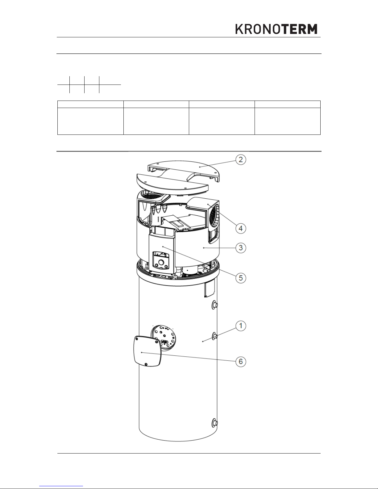
2. Structure of serial number
Example: 116390001-WXXYYZZZZ
W XX YY ZZZZ
1 2 3 4
1 2 3 4
KRONOTERM Year Calendar week
Serial number in
current year
(0001, 0002, 0003,
etc.)
3. Components
Page 5

ID.: 17-16-32-3052-02
4
6.2017
Page 6

ID.: 17-16-32-3052-02
5
6.2017
KOSOVNICA WP2 LF-202B
Number
Name
Ident
1 BOILER 200 L 2222000081126
2 AGGREGATE COVER 2222000076047
3 COVER RIM 2222000076030
4 AIR CONNECTOR 2222000077303
5 FRONT COVER 2222000081324
6 FLANGE COVER 2222000082086
7 COMPRESSOR 2222000081171
8 DIFFUSER 2222000076078
9 FAN 220 2222000016081
10 FAN HOLDER 2222000081225
11 EVAPORATOR 2222000081195
12 FILTER 2222000035051
13 THERMOEXPANSION VALVE 2222000075897
14 CONDENSING PLATE 2222000076061
15 ELECTRICAL CONNECTION COVER 2222000082093
16 WORKING THERMOSTAT 2222000081256
17 MAIN THERMOSTAT BUTTON 2222000081317
18 SAFETY THERMOSTAT 2222000048747
19 COMPRESSOR CAPACITOR 2222000083052
20 CONDENSE TANK 2222000077150
21 COMPRESSOR HOLDER 2222000083410
22 FLANGE 2222000004088
23 MAGNESIUM ANODE 2222000032388
24 DISPLAY HOLDER 2222000081270
25 FLANGE SEAL 2222000027124
26 VACUUM PIPE 2222000081652
27 PRESSURE PIPE 2222000081645
28 TERMOMETER 2222000081300
29 ELECTRIC HEATER 2222000082666
30 FLANGE INSULATION 2222000081751
31 PRESSURE SWITCH 2222000033460
32 COMPRESSOR SWITCH 2222000081294
33 ELECTRICAL HETER SWITCH 2222000081287
34 ANTIFREEZE THERMOSTAT 2222000081263
35 CAPACITOR FAN-1 2222000020804
36 CAPACITOR FAN-2 2222000081805
CONNECTION CABLE 2222000047436
COMPRESSOR CABLE 2222000083502
Page 7

ID.: 17-16-32-3052-02
6
6.2017
4. Cover removal – cover of electronic
To get acces to electronic components of the device it is necessary to remove the screws
(Imbus 4) on the cover of the device. Lift the cover up and remove it (1). Push the front cover
of the electronic up in the direction of the arrow (2) and pull it out towards you(3).
1
2
3
Page 8

ID.: 17-16-32-3052-02
7
6.2017
5. Electrical wiring diagram
1
Compressor - generator
7
Thermostat of evaporator
2
Fan
8
Electric heater switch 1-0
3
Compressor condenser
9
Compressor switch 1-0
4
Pressure switch
10 Temperature fuse
5
Working thermostat
11 Standard supply cable with plug
6
Connecting clip
12 Electric heater
13 Fan capacitor
RCS
1
1
2
1
2
3
3
4
5
6
7
8
9
10
11
PE
U1
U2
Z
2
13
12
14
10.1
10.3
1.1
S2
1.21.3
2
3.1
3.2
4.1
9
9.1
9.2
9.3
7
7.1
7.2
7.2
8
5
8.2
8.1
8.3
S1
1 2 3 4
5
6
6.1
6.2
6.3
10.2
4.2
15
789
10
11
12
7
8
13
14
Slika 1: El. Vezalna shema za izvedbe WP2 LF-202B
Page 9

ID.: 17-16-32-3052-02
8
6.2017
6. Tehnični podatki
Product:
Product:
Model:
WP2 LF
-
202B
Thermal power:
W
1850 (3350)*
Electrical power:
W
440 (1940 )*
Max. electrical power:
W
560 (60 °C) (2060)*
El. heater:
W
1500
Power supply:
V
~ 230
Coolant:
R134a (1,0 kg)
Max. water temperature:
°C
65
Needed air flow:
m3/h
500
Protection class:
IP21
Temperature of intake air:
°C
Od 10 do +40
El. protection
A
C 16, (~ 230 V)
Max. allowed pressure in the
heat pump:
Mpa
2,3 (23 bar)
* In case the el. Heater is turned on
DESIGNATION:
WP2 LF-202B
Volume:
l 200
Height:
mm 1698
Diameter:
mm 635
Dimensions of the wrapped
device WxDxH:
mm 700x680x1840
Joint mass:
kg 101
Highest allowed DHW
pressure:
MPa 1,0 (10 bar) pri 95 °C
DHW connections:
1''
Circulation connections:
¾''
Page 10

ID.: 17-16-32-3052-02
9
6.2017
Page 11

ID.: 17-16-32-3052-02
10
6.2017
Page 12

Company headquarters and production
Kronoterm d.o.o.
Trnava 5e
3303 Gomilsko
Tel.: (00386) 3 703 16 20 | Fax: (00386) 3 703 16 33 | Web-page: www.kronoterm.com |
E-mail: info@kronoterm.com | Customer support and service.: (00386) 3 703 16 26 |
E-mail.: servis@kronoterm.com
 Loading...