

Page 1
Installation instruction and user
manual
KT-2
Spatial corrector
The manual has to be handed over to the end user after installation.
ID.: 17-16-13-2960-03 | 1.2017
EN
Page 2
Id.: 17-16-13-2960-03 | 7.2017 2
Installation instruction and user manual of the spatial corrector KT-2
Id: 17-16-13-2960-03 | 7.2017
Printed in Slovenia, copyright: Kronoterm d.o.o.
This document is copyrighted. Any use outside the provisions of the copyright law without the
permission of Kronoterm d.o.o. is illegal and punishable by law. All previous versions of this document
are void. We reserve the right to make changes and printing errors.
Page 3
3 Id.: 17-16-13-2960-03 | 7.2017
1 Spatial Corrector KT-2
The spatial corrector KT-2 is user friendly and allows measurements and displays of room temperature,
adjustments of desired room temperature, the status of the heat circuit, settings of the circuit, status of
alerts, external temperature and clock.
2 Safety alerts
DANGER
Connecting the device to the power source can only be performed by a qualified installer in a
voltage-free state!
CAUTION
The spatial corrector must be connected properly. An incorrect connection can damage the
device. The manufacturer is not responsible for damage caused by incorrect installation
and/or improper use.
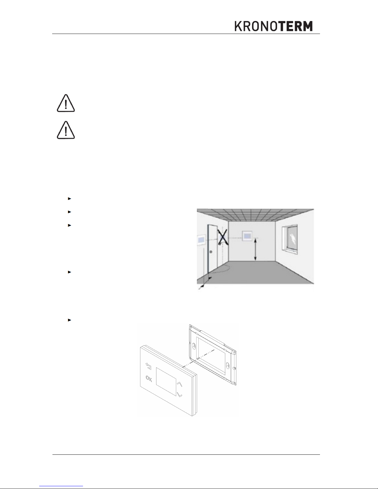
3 Installation
The Spatial corrector KT-2 must be installed in a room where the temperature is closest to your desired
average temperature of other rooms (hallway, living room).
The spatial corrector KT-2 is designed for installation on a flush-mounted electrical socket 3M
(GW 24 403 PM).
The spatial corrector is used for fixed installation in closed and dry rooms.
Recommended mounting height is between
1, 2 - 1, 5 m from the ground.
Do not expose the spatial corrector KT-2 to
direct sunlight, do not install it in the area of
air currents or air heated in any other way
(e.g. over electric cookers, refrigerators,
etc., or in the area of direct radiation heat of
radiators), because the heat affects the
control characteristics.
Do not install the spatial corrector KT-2 as
part of other electrical equipment, e.g.
dimmers, a possible heat emission could
affect proper operation.
4 Installation
Mount the spatial corrector KT-2 in:
A flush-mounted electrical socket 3M, H x W x D 106 x 74 x 48 mm
Connect the spatial corrector KT-2 and the TERMOTRONIC controller with a 4-wire data cable.
min. 20 cm
1,2 -
1,5 m
Page 4

Id.: 17-16-13-2960-03 | 7.2017 4
5 Connection of Spatial Corrector
Connect a routed 4-wire cable to the terminals A+, B-,
GND and +12 V of the spatial corrector KT-2.
NOTE
Connect the cables you have connected to the
spatial corrector KT-2 at terminals A+, B-, GND and
+ 12V to the same terminals in the electrical closet
controller TERMOTRONICTM.
In the case of a prefabricated cable, connect 1, 2 to A+; 3, 4 to
B
-
; 5, 6 to
+12 V
and 7, 8 to the
GND connection terminal on the spatial corrector KT-2.
NOTE
In the case of a direct connection of the spatial corrector KT-2 on the process module(PLC),
connect the cables from the spatial corrector KT-2 connected to terminals A+, B-, GND and
+12 V to the RJ-45 connector. Prepare the RJ-45 connector the same way as the one in the
wiring diagram below. Connect it to the connecting terminal TS on the PLC in electric closet
controller TERMOTRONIC.
UTP link between RJ
-
45 connector and
KT-2 TIA / EIA 568A connection of connector
Cable colors
RJ-45
A+
B-
GND+12V
KT-1
1
2
345
6
7
8
KT-2 RJ-45
A+
1
2
B-
3
4
12 V
5
6
GND
7
8
1 green
and white
2 green
3 orange and
white
4 blue
5 blue
and white
6 orange
7 brown white
8 brown
5.1 Binding multiple spatial correctors
6 Management of the spatial corrector
Key Function keys
RETURN:
Return from the menu and cancel
MENU:
Scroll through menus and confirm
»+« – set the value, move up
»-« – set the value, move down
,
LED indicator of set value
Page 5

5 Id.: 17-16-13-2960-03 | 7.2017
7 Initial connection
When connecting the data cable to the control
panel fort the first time, the regulating circuit
setup screen is displayed.
8 SETUP OF CONTROL LOOP
Set the desired heating circuit with the keys
and
. Press to confirm the settings.
The control panel confirms valid settings with
a multi-tone beep.
9 SYNCHRONISATION
The device is synchronising, wait a few
minutes
…
After a successful synchronisation, the control
panel is ready for use (see Qick user guide).
NOTE
Only one spatial corrector can control an individual control loop. Incorrect operation occurs if
two spatial correctors are installed on the same control loop.
10 CHNGE OR RESETTING OF CONTROL LOOP
NOTE
The recommended way to disconnect the power supply is by
disconnecting the electrical
fuse.
Page 6

Id.: 17-16-13-2960-03 | 7.2017 6
► Disconnect the device power supply.
► Reconnect the device power supply.
► Accessing the menu SETUP OF
CONTROL LOOP.
The menu “Setup of control loop” can be accessed only during the first minute of reconnecting the
control panel by holding the
and
keys for 8 seconds.
11 MAIN SCREEN
12 OPERATING STATUS
13 SETTING TARGET ROOM
TEMPERATURE
Operation of
control loop.
Operational
setting for
control loop.
The room temperature currently set is displayed
when the or arrow is pressed. The
temperature is highlighted with an orange border.
Fast heating of
tap water /
Fail-safe antifreeze mode
is active.
Device
maintenance of
required.
Desired room temperature can be set by pressing
the arrow again, the setting is confirmed by
pressing the icon, or is automatically confirmed
after 8 seconds.
Child safety lock
is active.
Multiple alarms /
errors active.
Circulation pump
of the control
loop is currently
active.
8
sek
1 4
2 5
3 6
7
Menu /
confirm
External
temperature
Menu down /
decrease value
Time
Back /
cancel
Room
temperature
Menu up /
increase value
Operating
status
8
sec
Room temperature
movement trend
Page 7

7 Id.: 17-16-13-2960-03 | 7.2017
14 MENU
NOTE
Contents and display of menus depend on model and configuration of device.
Operational setting for
control loop.
Setting night mode:
Fast heating of
tap water.
The display automatically dims in moderate
light.
Temperature setting
for tap water.
The display automatically dims in low light.
Display brightness
*Brightness is automatically
adjusted depending on
Surrounding light.
The display automatically dims in darkness.
Night mode.
Disable night mode. The display is always on.
15 CHILD SAFETY LOCK
The function is activated by pressing and
holding buttons and simultaneously for
2 seconds. The icon is displayed in the
status bar to indicate an active child safety
lock function. Key operation is disabled.
The function is deactivated by pressing and
holding buttons and f or 2 seconds
simultaneously. The function icon in status
bar disappears and normal button operation
is restored.
Child safety lock function prevents unauthorized access to the module. The function can also be
used to prevent unwanted button triggering while front panel cleaning.
16 QUICK MENU
The “Quick menu” can be accessed by
pressing the button. By pressing the
button, we navigate between System view and
Weather forecast menus. Weather can be
viewed for the next two days. By pressing
the button, we return to the Main menu.
OPOMBA
The Weather is only shown if the device is connected to the Internet and the location of the
device is set at the web interface Home Cloud.
2
2
sec
Page 8

Id.: 17-16-13-2960-03 | 7.2017 8
17 SYSTEM ERRORS
S01 – Data connection error between spatial corrector
and device. Check if the data cable is correctly connected
to the connector on the device. After the cause for the
error is resolved, the error is automatically confirmed.
If another error is displayed, please consult our technical
assistance.
http://www.kronoterm.com/servis/
18 Technical Device Information
Dimensions HxWxD: 80x80x8,6 mm
The resolution of the temperature sensor 0,1 °C
Adjustable range 17 – 27 °C
Modbus RS485 connection
Max. 4 x KT-2 units can be connected to TT3000
Weather
symbol
Highest (day-time)
temperature forecast
Air
Humidity
Day
of the
week
Lowest
(night-time)
temperature forecas
Device current
operation symbol
Water temperature
in the buffer tank
External air
temperature
Time
Temperature
of tap water
Page 9

9 Id.: 17-16-13-2960-03 | 7.2017
Page 10

Id.: 17-16-13-2960-03 | 7.2017 10
Page 11

11 Id.: 17-16-13-2960-03 | 7.2017
Page 12

The headquarters of the company and place of production
Kronoterm d.o.o.
Trnava 5e
3303 Gomilsko
Tel.: (00386) 3 703 16 20 | Fax: (00386) 3 703 16 33 | Web-page: www.kronoterm.com |
E-mail: info@kronoterm.com | Customer support and service.: (00386) 3 703 16 26 |
E-mail: servis@kronoterm.com
 Loading...