

Kronoterm HM-130 S1, HM-140 S1, HM-180 S1 Instructions For Installation, Use And Maintenance Manual
Page 1

Instructions for installation, use
and maintenance
Hydro module
HM-130 S1
HM-140 S1
HM-180 S1
The manual has to be handed over to the end user after installation.
Id.: 17-17-46-4358-01 | 09.2017
Page 2

2
Content
1 Important information 4
1.1 Symbols 5
1.2 Definitions 5
1.3 General warnings 5
1.4 Safety warnings and instructions 6
1.5 Obligations of the end user 7
1.6 Obligations of the installer 8
1.7 Obligations of the authorised contractor for commissions 8
1.8 Package and worn-out device management 8
1.9 Delivery package 9
2 INSTRUCTIONS FOR THE END USER 10
2.1 Controlling the device and heating system 11
2.2 Maintaining the device and heating system 11
2.2.1 Operation malfunctions 11
3 Instructions for the installer 14
3.1 Transport and storage 15
3.2 Installation space 15
3.3 Wall mounting 16
3.4 Connection with the outdoor unit 17
3.4.1 Cooling connection with the outdoor unit - HM-140 S1 and HM-130 S1. 20
3.4.2 Cooling connection with the outdoor unit - HM-180 S1 22
3.4.3 Make a leak test, drain and fill the cooling connection. 23
3.5 Hydraulic connection 24
3.5.1 General 24
3.5.2 Buffer tank for DHW connection 25
3.5.3 Connecting the heating system 27
3.5.4 Filling the heating system 35
3.6 Electrical connection 36
3.6.1 Description of elements in the electrical cabinet 37
3.6.2 Electrical connection with the outdoor unit 38
3.6.3 Cable installation 39
Page 3

3
3.6.4 Power connection 39
3.6.5 Connecting the communication with the external device 41
3.6.6 Connecting the external temperature sensor 42
3.6.7 Connection KT-1 and/or KT-2 42
3.6.8 Connecting the heating for DHW 43
3.6.9 Heating cycle connection 43
3.6.10 External additional source connection 46
3.6.11 Connecting the valve for switching between cooling / heating 47
3.6.12 Connecting the signal for PV signal 48
3.6.13 Connecting the signal for remote off 48
3.7 Commissioning of the device 48
4 Technical characteristics 49
4.1 Dimensions and characteristics 50
4.1.1 HM-130-S1 and HM-140-S1 50
4.1.2 HM-180-S1 51
4.1.3 Features 52
4.1.4 Machine scheme 52
4.1.5 Electrical scheme 53
4.2 Technical data 54
4.3 Legend of serial labels 56
4.4 Accessories 57
4.4.1 Installation of the Expansion vessel 57
Page 4

4
1 IMPORTANT INFORMATION
The manual describes the process of installation, maintenance and safe use. The
installation and maintenance can only be performed by qualified personnel. Read this
manual carefully before installation, maintenance or use.
The manual has to be handed over to the end user after installation.
In case the product shall be given to a third person for use, the manual has to be
handed over to them as well.
Page 5
5
1.1 Symbols
Incorrect installation, maintenance or use can cause a malfunction of the device, damage
the user o property. For limiting risks, the important information in this manual is highlighted
with symbols.
These symbols mark various risks for the user or the device.
DANGER: Risk of situations which can lead to serious physical injuries.
WARNING: Risk of situations which can lead to minor physical injuries.
CAUTION: Risk of situations which can lead to damage or malfunction
of the device.
This symbol marks information for the user.
NOTE: A notice which holds important information regarding
requirements of the manufacturer and the device.
1.2 Definitions
An informed person is a person who reads this manual.
A qualified person is a professionally qualified person.
An authorised commission contractor is trained by the manufacturer and
authorised to perform commission.
An authorised technician is trained and authorised by the manufacturer to
perform maintenance and servicing of the device.
The user uses the device according to its use.
The installer is a person professionally trained for performing hardware and/or
electro-installation work and mounting of the device.
1.3 General warnings
NOTE
Read the instructions for use and installation before installation.
NOTE
Any remaking or replacement of original components of the device eliminates the
manufacturer’s guarantee for safe and functional operation. In the case of
undesignated and incorrect use of the device, the manufacturer is not responsible for
the consequences and will not acknowledge claims for damages in these cases. The
user is solely responsible for injuries and damages on the device itself or on other
objects resulting from undesignated and incorrect use of the device.
NOTE
The installation of the device has to be performed in accordance with the manual;
otherwise the manufacturer does not acknowledge the warranty.
Page 6
6
NOTE
High pressure in the heating system can cause water dripping from the safety valve.
Make sure the drainage pipe on the side of atmospheric pressure is open.
CAUTION
A yearly inspection of the safety valve is necessary to ensure its proper operation;
when performing it, remove lime scale and make sure the safety valve is not blocked.
CAUTION
The drainage hole of the safety valve must be directed downwards. Make sure it does
not freeze.
DANGER
Failure to comply with the manual and good practise while connecting the device to
the power supply can lead to serious injury or death.
WARNING
Connecting the device to the power source can only be performed by a qualified
installer.
1.4 Safety warnings and instructions
DANGER
It is prohibited to move, shift, clean or service the device while in operation.
WARNING
It is prohibited to play with the device. Children are not allowed to clean the device
without supervision.
WARNING
The device can be operated independently only by informed persons who are familiar
with the safe operation of the device and understand possible hazards of its operation.
Children older than 8 and people with reduced physical and mental capacities and
with lack of experience and knowledge can only operate the device under the
supervision of an informed person.
WARNING
Before installation and any further adjustments to the device, it is necessary to
consider the instructions for safe use and maintenance.
WARNING
Installation has to be performed in accordance with national regulations on electrical
installations and with the instructions of the manufacturer. It has to be performed by a
professionally trained person.
WARNING
It has to be made sure that the device does not endanger anybody. Access to the
device has to be denied to children and persons who are not informed about the
operation of the device.
WARNING
The device must never be cleaned with cleaning agents containing sand, soda, acid
or chlorides because these might damage the surface of the device.
WARNING
The device contains the refrigerant HFC which is classified as a greenhouse gas
according to the Kyoto protocol. This is why tampering with the cooling cycle is only
allowed to persons authorised for working with the coolant as defined by the national
Page 7
7
legislation in force. While performing works on the device, it is necessary to prevent
the coolant to leak into the atmosphere.
WARNING
It is necessary to consider all technical data and instructions in this manual as well as
all warnings and notes during planning, design, installation and use of the device.
WARNING
Electrical installations have to be inspected in accordance with regulations on the
requirements for low voltage electrical installations in buildings by the installer of
electrical installations.
DANGER
Connecting the devices power cable must be performed by a qualified electrician.
During the procedure, the device must not be live.
WARNING
In case the power cable of the device is damaged it has to be immediately replaced.
The replacement can only be performed by the installer or authorised maintenance
worker.
WARNING
Before opening the device, disconnect all electrical circuits and make sure the device
is not live.
CAUTION
Putting any kinds of items on or next to the device is prohibited.
CAUTION
The device must not be placed in a room where it cannot be removed. Later walling or
setting up of other obstacles next to the device is forbidden.
CAUTION
For the correct operation of the device, the electrical distributor has to provide
electricity of adequate quality (SIST EN 50160). In normal conditions, this is within ±
10 % of the rated voltage. The data about the state of the electrical grid have to be
acquired from the electrical distributor.
CAUTION
Connecting the device to the electrical network has to be performed in accordance
with the standards for connecting devices to the electrical network. Connect the
device to the electrical network via the power supply cut-off which is installed into the
electrical installation under the regulations in force.
1.5 Obligations of the end user
The user must ensure uninterrupted and efficient operation of the device by considering the
following instructions:
To thoroughly study the instructions for use and installation accompanying the
device before use.
To have a qualified and authorised installer perform the installation of the device.
To have a contractor for commissions perform the commission.
Allow the authorised contractor for commissioning or ask him or require him to
thoroughly explain the functioning and how to operate the device.
Ensure regular yearly inspections and maintenance of the device by the authorised
maintenance worker.
Page 8
8
Store this manual in an appropriate dry place close to the device.
1.6 Obligations of the installer
The installer is responsible for installing the device in accordance with the following
requirements:
To thoroughly study the instructions for use and installation accompanying the
device before installation.
To install the device in accordance with the instructions and national legislation,
policies and standards in force.
1.7 Obligations of the authorised contractor for
commissions
CAUTION
The first commission can only be performed by the contractor of commissions
appointed by the manufacturer in accordance with the instructions for commission.
The contractor for commissions is responsible for commissioning the device in accordance
with the following requirements:
The contractor performs the first commission and eliminates all eventual
irregularities found during commission.
Trains the user for operating the device and settings.
Alerts the user to regularly maintain the device for keeping the device functioning
properly throughout its entire lifespan.
To give the user all the documentation accompanying the device.
1.8 Package and worn-out device management
Sort the package according to cardboard, wood and foil and dispose of it in
appropriate containers.
After the lifespan of the device ends it has to be disposed of in accordance with the
legislation in force on waste electrical and electronic devices and devices with F-
gasses.
Refrigerant
The device has to be connected to the outdoor unit which holds the HFC coolant which is a
fluorinated greenhouse gas covered in the Paris protocol. You have to prevent leakage of
the gas into the atmosphere. During a maintenance procedure or removal of the device it
has to be made sure that the gas is removed in accordance with the current regulations on
the use of fluorinated greenhouse gasses.
Page 9
9
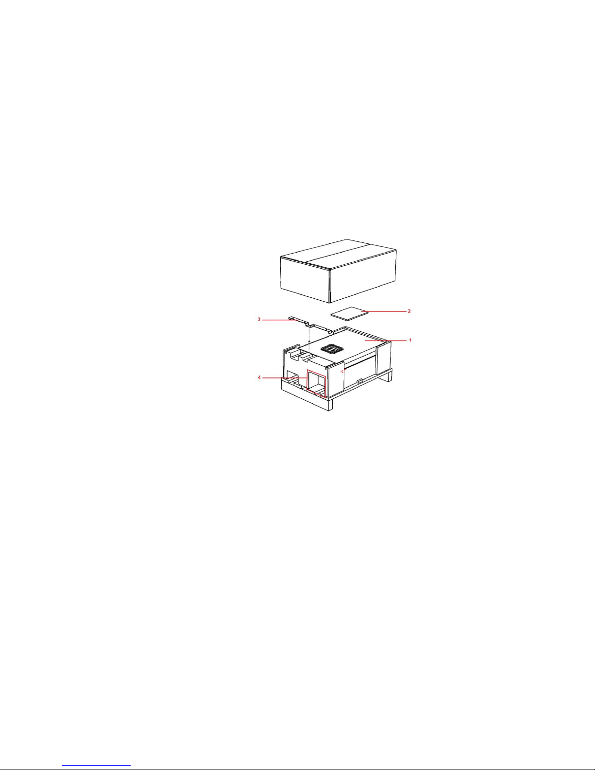
1.9 Delivery package
The package includes:
1. Hydro module.
2. Instructions for management and instructions for installation, use and maintenance.
3. Wall bracket for the device,
4. Accessories:
o Outdoor air temperature sensor (only HM-140 S1),
o DHW buffer tank temperature sensor,
o Second mixing cycle temperature sensor,
o Equalisation screw -2x
Picture 1: Delivery package
Page 10

10
2 INSTRUCTIONS FOR THE END USER
Page 11
11
2.1 Controlling the device and heating system
Use the device and heating system in accordance with this manual and instructions for use
of the heat pump which explains the use off the device and heating system.
2.2 Maintaining the device and heating system
The device must be visually inspected once a year. The electrical and hardware installation
of the device have to be inspected. In the case of detected irregularities, contact the
authorised technician.
CAUTION
The servicing and maintenance of the device can only be performed by a person
authorised by the manufacturer. In case of a malfunction, first contact the installer
who installed the device.
NOTE
Cleaning of water filters on the return into the device is advised to be performed at
least once yearly.
CAUTION
A blocked water purifying component and magnetic filter can lead to a malfunction
of the device or incorrect functioning of the device. In case the display displays a
warning of flow malfunction (”Caution, flow!”).
NOTE
Periodically, once yearly, check the water temperature in the heating system.
NOTE
In case the pressure falls (i.e. Leakage of the system) the display displays a
warning of flow malfunction (”Caution, flow!”).
2.2.1 OPERATION MALFUNCTIONS
In case of a malfunction during the operation of the device, the display of the
TERMOTRONIC controller displays the warning “Caution, malfunction”.
Find the malfunction description in the “Owner’s manual”. For error correction call the
installer who installed the device.
2.2.1.1 Resetting the thermal protection of the built-in electrical
heater
The thermal protection of the electrical heater is an additional safeguard protecting the
device in the following cases:
Page 12
12
The electrical contactor which turns on the electrical flow heater can be
permanently short-circuited.
At commission, air is in the system, which causes heating without heat extraction.
The easiest way to determine whether the thermal protection of the electrical heater is
turned off is to turn on the operation of the auxiliary source on the TERMOTRONIC control
unit. If the electric heater is operational, the water temperature in the heating system will
start to rise.
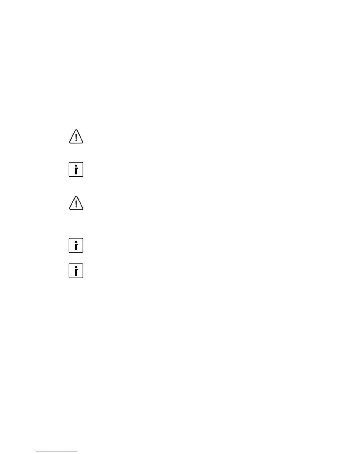
In case the electrical heater does not work because of one of the before mentioned
reasons, the safety thermostat has to be reset after the problem is resolved. It is reset by
pushing the red button. If the reset is successful, you will hear a “CLICK”.
Picture 2: Resetting the safety thermostat of the built-in electrical heater
Page 13

13
Page 14

14
3 INSTRUCTIONS FOR THE INSTALLER
Page 15
15
3.1 Transport and storage
WARNING
Valves, safety elements and pipes must be checked, calculated and
determined by the system or hardware installations contractor.
WARNING
Before connecting the device, it is necessary to rinse the pipe system
thoroughly and remove impurities (solid particles, oils, greases ...).
Use suitable detergents if necessary.
NOTE
The device must be connected via closing valves.
CAUTION
The device must be transported with transport devices.
Secure the device during transport to prevent damage.
The device must not be stacked and other objects must not be placed on it.
CAUTION
Appropriate transport equipment must be used for installing the device. Safety
regulations and good practise have to be used.
CAUTION
The device has to be stored in a dry and clean place. The allowed storing
temperature is between 10 °C and 45 °C, for a short period (up to 24h) also up to
50 °C.
3.2 Installation space
The device must be installed in a space which meets the following requirements:
NOTE
The installation space must be accessible by manual transport devices for the
purposes of installation, maintenance and servicing.
Costs connected with hiring special equipment for installing the device,
servicing and maintenance are charged to the operator separately and are
not subject of the warranty.
NOTE
The location of the internal unit must be dry and in the temperature range between
+10 °C and 40 °C.
WARNING
The space has to be fitted with a drain.
CAUTION
It is forbidden to install the device under water pipes; in case of leakage water
could enter the device and cause a malfunction.
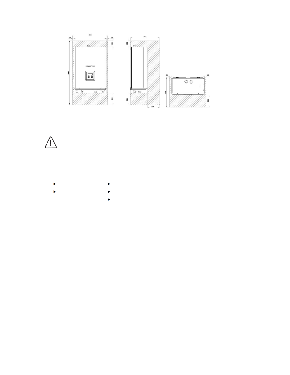
NOTE
It is obligatory to consider the minimal clearance from obstacles for ensuring
unobstructed access for maintenance and service of the device.
Page 16
16
Picture 3: Minimal clearance between the device and obstacles
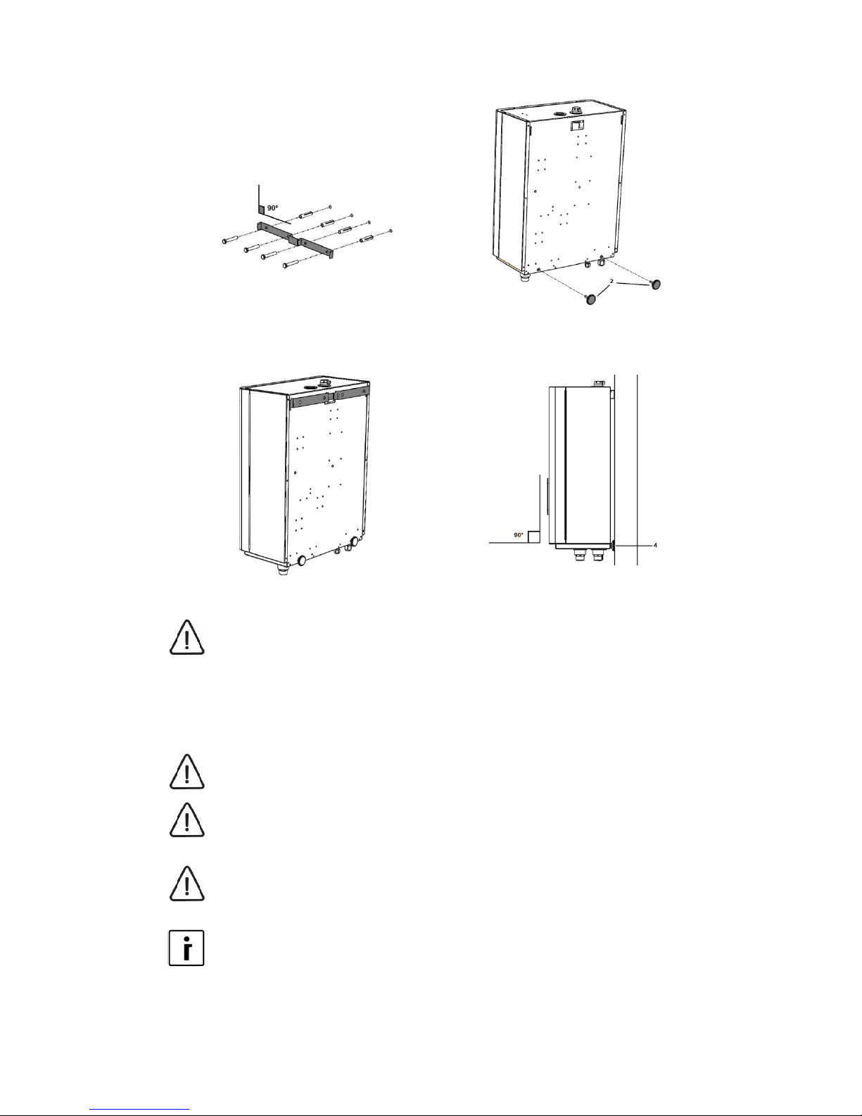
3.3 Wall mounting
CAUTION
For wall mounting, you need to use wall plugs and screws suitable for the wall.
Take into account the mass of the device. For technical information, see section
on technical information.
For wall mounting, you will need:
Spirit level,
Drilling machine,
Plugs and screws suitable for the wall,
Pencil or pen for marking the places for holes and screws,
Device wall mount (part of the delivery package).
1. Attach the wall mount:
a. Mark the position of holes for
attaching the wall mount - use the wall
mount of the device and the spirit
level.
b. Drill holes suitable for selected
mounts and screws.
c. Insert the plugs, fasten the wall mount
and level it.
2. Tighten the equalisation screws in the
device - 2x.
Page 17
17
Picture 4: Fastening the device’ s wall mount
to the wall
Picture 5: Installation of equalisation screws.
3. Hang the device on the wall mount.
4. Level the device using the spirit level
and equalisation screws.
Picture 6: Hang the device on the wall mount.
Picture 7: Level the device using the
equalisation screws.
CAUTION
The mass of the device, safety regulations and good practise have to be followed
when lifting the device. For technical information, see section 4.2.
3.4 Connection with the outdoor unit
CAUTION
Connection with the outdoor unit must be performed by a refrigeration expert.
CAUTION
The pipeline and electrical cables have to be protected with heat and waterproof
insulation in a protective pipe.
CAUTION
The device is filled with pressurised N2. Before attaching the pipe, it must be
released from the device.
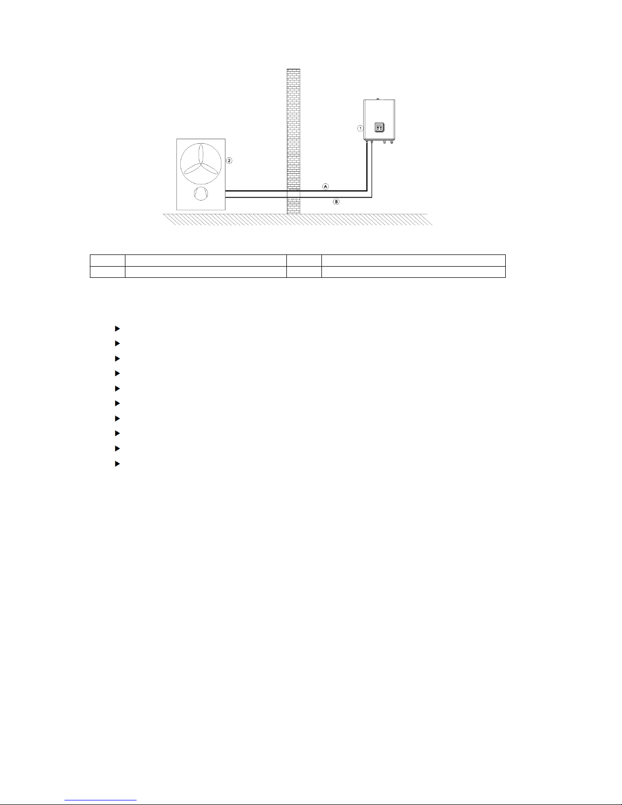
NOTE
For making the connection with the external device, see Instructions for
Installation of the external device.
Page 18
18
Picture 8: Coolant connection between the exterior and interior device.
1
Hydro module
A
Gas pipe
2
Outdoor unit
B
Liquid pipe
You will need the following tools:
Screwdriver.
Coolant service manometer.
Tool for cutting pipes.
Tool for deburring pipes.
Fork wrench and fork torque wrench - for HM-140 S1 and HM-130 S1.
Tool for pipe edging - for HM-140 S1 and HM-130 S1.
POE oil is suitable for cooling systems - for HM-140 S1 and HM-130 S1.
Pipe expander - for HM-180 S1.
Acetylene burner, oxygen - for HM-180 S1.
Wet towel.
Page 19

19
For making a cooling connection with the external device, follow these steps:
1. Remove the front cover of the device.
Picture 9: Removal of the device cover.
2. Unscrew the screws of the electrical cabinet and open it to ensure access to the
cooling pipes. Unscrew the lid of the service valve.
Picture 10: Opening the electrical cabinet.
Page 20

20
3. If you are installing HM-140 S1 or HM-130 S1, continue on chapter 3.4.1. If you
are installing HM-180 S1, continue on chapter 3.4.2.
3.4.1 COOLING CONNECTION WITH THE OUTDOOR UNIT - HM140 S1 AND HM-130 S1.
4. Connect the manometer and drain the N2 from the device.
5. Unscrew the bolts on the end of the pipe and save them. You will use them to
mount the pipes.
6. Cut the connecting pipes to the required length. When cutting, consider the
following:
Use a pipe cutter which does not leave chips to cut the pipe.
The cut must be perpendicular to the pipe’s axis and straight.
1
Copper pipe
3
Uneven
2
Inclined
4
Rough
7. Deburr the end of the pipe:
Remove all chips from the part where the pipe was cut.
Hold the pipe downwards during deburring so that the chips do not fall into
the pipe.
1
Copper pipe
3
Deburring tool.
Page 21

21
2
Copper pipe held downwards
8. Attach the bolt you have previously removed from the device onto the pipe as seen
below.
1
Copper pipe
2
Screw nut
9. Edge the end of the pipe with the edging tool.
1
Holder
4
Cone
2
Copper pipe
5
Bracket
3
Fitting
6
Handle
7
Holder
Mount the copper pipe firmly into the tool for edging. Consider the dimensions listed
in the table below.
External diameter
‘'A''
[mm]
[inch]
[mm]
9.52
3/8
1.5 ~ 1.7
15.88
5/8
1.6 ~ 1.8
10. Check the end of the pipe:
Compare the edging of the pipe with the picture below.
In the case of damaged edging cut the part off and repeat the edging procedure.
Page 22

22
1
Circular edging of the pipe of the same length.
4
Inclined edge
2
Circularly smooth edge
5
Uneven surface
3
Interior edge and surface without scratches
6
Cracked / rough
7
Unequal thickness
11. Align the edged cooling pipe with the connection of the same dimension on the
internal unit.
12. Apply a drop of oil on the bolt thread (POE oil, suitable for cooling systems) to
grease the thread.
13. Tighten the bolt manually.
14. Set the torque wrench to the suitable setting.
External diameter of the pipe
Torque
[mm]
[inch]
[Nm]
9.52
3/8
34 – 42
15.88
5/8
65 – 81
15. Use the fork wrench and fork torque wrench to tighten the bolt until it clicks.
16. Repeat the process for both pipes.
3.4.2 COOLING CONNECTION WITH THE OUTDOOR UNIT - HM180 S1
The pipe connection for HM-180 S1 is performed with soldering the connecting pipes to the
connections on the device. Follow the steps below.
1. Use the pipe cutter to cut the pipes approximately 3 cm from the end of the pipe.
2. Clean the pipes with an abrasive cloth to remove impurities. When cleaning, be
careful not to let the impurities enter the pipe.
3. Expand the pipe with the tool for expanding pipes.
Page 23

23
Inside diameter – Φ22,2 - ±0,2
4. Align the expanded connecting pipes with the connections. Wrap a wet towel
around the connections on the internal unit for cooling. Solder the pipes with
soldering which contains at least 5% Ag.
5. Check the quality of the joints.
3.4.3 MAKE A LEAK TEST, DRAIN AND FILL THE COOLING
CONNECTION.
NOTE
To perform the leak test, drain the system and fill the system, see Instructions for
Installation, Use and Maintenance of the outdoor unit.
Page 24

24
3.5 Hydraulic connection
3.5.1 GENERAL
WARNING
Circulation pumps, valves, safety elements and pipes must be checked,
calculated and determined by the system or hardware installations contractor.
WARNING
Before connecting the device, rinse the whole heating system and remove
impurities. Remove all detergent residue. Flushing the system must be performed
with new and existing heating systems.
3.5.1.1 Legend of symbols of the hydraulic piping diagrams
Symbol
Description
Symbol
Description
Circulation pump
Drinking water filter
Ball valve
Manometer
Ball valve with exhaust
Thermometer
Three-way switch valve
Pressure regulator
Three-way mixing valve
Consumer of heat / coolness
Expansion vessel
KT-1, KT-2
Safety valve
Thermostat
Hydraulic divider
Pipe safety thermostat
Non-return valve
Electrical cabinet for powering the
devices of the heating system
Cyclone magnetic separator
of impurities
Temperature sensor
Automatic vent
Automatic by-pass control valve
1
Hydro module
17
Buffer tank
2
Air-water Heat Pump
18
Circuit circulation pump
3
Buffer tank for DHW
19
Pipe safety thermostat
4
Three-way switch valve
20
Three-way mixing valve
5
Heat consumer
21
Gas furnace
6
Overflow valve
22
Hydraulic divider
7
Cyclone magnetic separator of impurities
23
Oil or pellet furnace
8
Heating system Expansion vessel
24
Drain
9
Heating system safety valve
25
Expansion regulation TT 3003 - MD2
10
Circulation pump
26
Submersible electric heater
Page 25

25
11
Irreversible flaps
27.1
Combined buffer tank with submersed buffer
tank for DHW
12
Safety valve of the DHW system
27.2
Buffer tank for DHW submersed in the buffer
tank
13
Expansion vessel of the DHW system
28
Biomass furnace
14
Irreversible flaps
29
Biomass furnace circulation pump
15
DHW system pressure regulator
30
Solar collectors circulation pump
16
DHW water filter at the inlet of the building
31
Three-way cooling switch valve
A
Cooling connection - gas pipe
C3
Modbus cable for communication between
internal and outdoor unit
B
Cooling connection - liquid pipe
C4
Expansion regulation TT 3003 - MD2 electrical
supply cable
C1
Internal unit electrical supply cable
C5
Cable for communication between internal unit
and expansion regulation TT 3003 - MD2.
C2
Outdoor unit electrical supply cable
Certain elements are additionally marked with the designation of the electrical connection.
MD1
:
A2 Designation of the connecting clamp.
MD1 - electrical connection of the element to the device’s connecting terminal
.
MD2 - electrical connection of the element on the connecting terminal of the
expansion regulation TT3003 - MD2.
3.5.2 BUFFER TANK FOR DHW CONNECTION
CAUTION
Connect the buffer tank for DHW in accordance with the national and local regulations
in force. The space where the device, DHW buffer tank, etc. are installed, must have a
floor drain to allow water to drain in case of a spill.
CAUTION
Connect the DHW buffer tank so as to prevent galvanic cells and corrosion to form
because of the use of different materials. We recommend connections made of red
brass at least twice the length of the rated diameter of the connection.
CAUTION
The DHW buffer tank is intended for storing drinking water. The drinking water must be
in accordance with the national regulations on drinking water in force.
CAUTION
For normal operation of the Expansion vessel, it is necessary to perform proper
adjustments of the tank’s working pressure. The settings have to be checked every 12
months.
3.5.2.1 Choosing the buffer tank for DHW
For reliable DHW heating, you need a DHW buffer tank which has a heat exchanger with
the appropriate surface. Consider the recommendations below.
Hydro module
Min. surface of the DHW buffer tank heat exchanger
HM-140-S1
1,8 m2
HM-130-S1
3.0 m2
HM-180-S1
4.5 m2
Choose the DHW buffer tank volume to meet the needs for comfort.
Page 26

26
3.5.2.2 Connecting the buffer tank for DHW
Connect the buffer tank for DHW as shown on the scheme below.
NOTE
For circulation regulation (10), you must install the expansion regulation TT3003 (25).
Picture 11: Connecting the buffer tank for DHW
3.5.2.3 Choosing and setting the expansion vessel of the DHW
system
NOTE
The cold DHW connection must be fitted with an expansion vessel suitable for
drinking water. The selection and installation must be in accordance with the
standard DIN 4807 T5.
CAUTION
Consider the maximal operational pressure of the vessel.
The size and type of the expansion vessel must be determined by the installer / contractor
according to the size of the system. The table below lists some recommendations.
Adjusting the safety valve [MPa (bar)]
0.6 (6.0)
System pressure [MPa (bar)]
0.3 (3.0)
0.35 (3.5)
0.4 (4.0)
Volume of the DHW [l]
Expansion vessel [l]*
200
5 8 12
300
15
19
26
Expansion vessel for DHW is factory filled to a precharge pressure p0 with dry nitrogen.
The pressure must be set depending on the settings of the pressure reducing valve on the
DHW supply to the building.
The pressure in the expansion vessel must be set according to the following formula:
,
Page 27

27
p0 – precharge in the Expansion vessel
prv – setting pressure regulator
Example:
The Expansion vessel is filled with nitrogen to a pressure of p0 = 2,0 bar (0,2 MPa).
The pressure regulator for drinking water at the inlet of the building is set to prv = 4.0 bar
(0,4 MPa).
Consequently, the Expansion vessel must have the following pressure:
The expansion vessel must be supplemented with dry nitrogen to 3.8 bar.
3.5.3 CONNECTING THE HEATING SYSTEM
WARNING
Thorough venting of the system has to be ensured. Otherwise, malfunctions in
operation may occur.
CAUTION
The device can be integrated with an expansion vessel with the volume of 12l. This is
sufficient for heating systems up to the joint volume of 300 l and maximal operating
pressure of 0.3 MPa (3bar). In case of a heating system of a larger volume, it is
necessary to install an external expansion vessel. The dimensions of the Expansion
vessel must be in accordance with standard EN 12828.
For installing the expansion vessel, see chapter 4.4.1
CAUTION
For normal operation of the Expansion vessel, it is necessary to perform proper
adjustments of the tank’s working pressure. The settings have to be checked every 12
months.
CAUTION
The heating system must be fitted with a safety valve set to 0.3 MPa (3 bar).
3.5.3.1 Mono-energy system
A mono-energy system is a heating system which supplies all the heat from the heat pump
and integrated electric heater.
3.5.3.2 System with one heating cycle and DHW buffer tank
The scheme below shows a heating system with one cycle and a DHW buffer tank.
CAUTION
This model is suitable only for systems with floor, wall or ceiling heating.
Page 28

28
CAUTION
Ensure the minimal volume of the heating system as stated in the table below. If
needed, install an additional buffer tank on the return pipe.
Max. Thermal power (kW)
System min. volume (L)
8
150
11
200
16
300
19
350
22
400
CAUTION
To ensure sufficient flow, make sure that at least 30% of the branches of the heating
system do not have electrical or thermostat closing valves.
CAUTION
Set the overflow valve (6) not to let water through in normal operation. Consider
manufacturer’s instructions.
NOTE
For circulation regulation (10), you must install the expansion regulation TT3003
(25).
Picture 12: One cycle heating system with cooling switch and DHW buffer tank
3.5.3.2.1 System with several heating cycles, buffer tank and DHW buffer
tank
NOTE
An expansion regulation TT 3003 - MD2 must be installed for regulation of the third
cycle (5.3), fourth cycle (5.4) and circulation (10).
CAUTION
A buffer tank with the volume of at least 15 l / kW of heating power has to be
installed.
Example:
The highest heating power of the device Q
hmax
= 11 kW.
Page 29

29
The minimal volume of the buffer tank V
min
= 11 kW x 15 L/kW = 165 L
Picture 13: Scheme of a system with several heating cycles, buffer tank and DHW buffer tank
3.5.3.3 Bivalent system
A bivalent system uses an additional heat generator in addition to the heat pump to heat
the building.
Set up the bivalent system in accordance with the schemes below.
Page 30

30
3.5.3.3.1 Bivalent system with oil or pellet furnace
NOTE
An expansion regulation TT 3003 - MD2 must be installed for regulation of the third
cycle (5.3), fourth cycle (5.4) and circulation (10).
Picture 14: Scheme of a bivalent system with oil or pellet furnace.
3.5.3.3.2 Bivalent system with gas furnace
NOTE
An expansion regulation TT 3003 - MD2 must be installed for regulation of the third
cycle (5.3), fourth cycle (5.4) and circulation (10).
Picture 15: Scheme of a bivalent system with gas furnace.
Page 31

31
3.5.3.3.3 Bivalent system with biomass furnace
NOTE
An expansion regulation TT 3003 - MD2 must be installed for regulation of the third
cycle (5.3), fourth cycle (5.4), circulation (10) and biomass furnace (28).
Picture 16: Scheme of a bivalent system with biomass furnace
3.5.3.3.4 Bivalent system with solar collectors
Install a system with solar collectors according to the scheme below.
NOTE
An expansion regulation TT 3003 - MD2 must be installed for regulation of the third
cycle (5.3), fourth cycle (5.4), circulation (10) and solar collectors (28).
Picture 17: Scheme of a heating system with solar collectors
Page 32

32
3.5.3.4 Cascade piping of devices
The scheme below shows parallel or cascade piping of devices.
NOTE
Contact our clerk for regulation of parallel operation of multiple devices.
Picture 18: Cascade piping of devices
Page 33

33
3.5.3.5 Quality of heating water
WARNING
The table below lists maximal allowed content of substances in heating water. If the
influence of a substance on the device is marked as »-« or »0«, the water must not be
used.
TYPE OF PRESENT
SUBSTANCE
UNIT
CONCENTRATION
INFLUENCE TO THE
HEAT CONDUCTOR
Organic sediment
mg / L
0
Ammonia NH
3
mg / L
< 2
1 to 20
> 20
+
0
-
Chloride
mg / L
< 300
> 300 + 0
Allowed water hardness
°dH
5 – 10
Electrical conductivity
µS / cm
< 10
10 to 500
> 500
0
+
-
Iron (Fe) removed
mg / L
< 0.2
> 0.2 + 0
Free carbonic acid
mg / L
< 5
5 to 20
> 20
+
0
-
Manganese (Mn) removed
mg / L
< 0.1
> 0.1 + 0
Nitrates (NO3)
removed
mg / L
< 100
> 100 + 0
pH value
mg / L
< 7.5
7.5 to 9
> 9
0
+
0
Oxygen
mg / L
< 2
> 2 + 0
Hydrogen sulphide
(H2S)
mg / L
< 0.05
> 0.05 + -
HCO3- / SO
4
2
-
mg / L
> 1
< 1 + 0
Hydrogen carbonate
(HCO3-)
mg / L
< 70
70 to 300
> 300
0
+
0
Aluminium (Al) removed
mg / L
< 0.2
> 0.2 + 0
Sulphates
mg / L
< 70
70 to 300
> 300
+
0
-
Sulphite (SO3)
mg / L
< 1
+
Chlorine (gas) (Cl2)
mg / L
< 1
1 to 5
> 5
+
0
-
Table: Influence of various aggressive substances in heating water on the device. (+ = no
influence, 0 = danger of corrosion, - = corrosion - use not permitted).
CAUTION
The heating system has to be filled with water with the hardness between 5 °dH and
10 °dH. Malfunctions of the device because of water hardness are not covered by the
Page 34

34
warranty.
The heating systems must not be filled with dirty or corrosive water. Add corrosion
inhibitors and anti-microbial agents to water.
CAUTION
The water in the heating system must be in accordance with the regulations of
standard VDI 2035 and must not contain micro-organisms. Fill the heating system
with soft water with added additives for ensuring the required quality.
NOTE
To prevent malfunctions of the hydraulic components of the system, we
recommend installing a SpiroVent RV2 air bleeder (micro-bubbles). The presence
of micro bubbles in the system eventually forms larger bubbles which in time can
cause corrosion of the system, system component malfunction and operation
disturbance.
In new systems, impurities are the result of residue from welding, soldering, dirty pipes (oil,
grease), etc. In case the impurities start accumulating in the device, this can worsen the
flow and heat transfer, in worst cases also freezing of water in the heat exchanger and
consequently the destruction of the device.
WARNING
To protect the device from intake and accumulation of dirt in the heat exchanger
you must install the strainer and magnetic separator on the return pipe for heating,
before entry into the device.
WARNING
A galvanic disconnection between individual elements of the heating system (i.e.
boiler, buffer tank...) is obligatory.
In the case of using steel pipes in the heating system, it is necessary to degrease them
(the interior of the pipe) before connecting them to the heat pump.
Page 35

35
3.5.4 FILLING THE HEATING SYSTEM
Picture 19: Static height of the heating system
7
Expansion vessel
8
Safety valve
H
Static height (the height difference between the expansion vessel and the highest
point of the heating system).
CAUTION
Consider the maximal operational pressure of the vessel.
NOTE
Inappropriate filling of the expansion vessel with precharge p0 and filling the
heating system, the function of the expansion vessel and operation of the heating
system is not guaranteed.
NOTE
The dimensions of the Expansion vessel must be in accordance with standard
EN 12828.
Setting the pressure for the Expansion vessel
Before filling the system with water, check and set the pressure of the expansion
vessel p0. The surcharge and maximal pressure of the expansion vessel are
specified on the standard label.
Calculate the value of the lowest needed surcharge p0 setting:
Page 36

36
CAUTION
If the calculation shows a pressure lower than 0.1 MPa (1 bar), set the pressure of
the expansion vessel to 0.1 MPa (1 bar).
p0 [MPa (bar)] – surpressure in the Expansion vessel,
p
0min
[MPa (bar)] – minimal needed pressure of the heating system,
p
0max
[MPa (bar)] – maximal allowed pressure of the heating system,
H [m] – static height.
Set the surcharge in the expansion vessel by releasing or supplementing dry
nitrogen.
Record the new value of the surcharge p0 on the serial label.
Open the closing valve of the Expansion vessel carefully, open the vents and close
the drain.
Filling the heating system
Use the filling valve to fill the system with water of suitable quality to the pressure
pF.
,
Filling the system to the final pressure
The final pressure of the system is determined by heating the system to the
maximal heating temperature (thermal degassing).
Turn off the circulation pumps, open the vents and vent the system.
At maximal operating temperature, fill the system to the end pressure which is 0.05
MPa (0.5 bar) lower than the releasing pressure of the safety valve.
],
( )
pE – the end pressure of the system,
pSV – the pressure of the safety valve.
3.6 Electrical connection
Connect the internal unit to the mains according to the instructions described in this
chapter.
CAUTION
Connecting the device to the electrical network has to be performed in accordance
with the standards for connecting devices to the electrical network. The device has
to be connected to the electrical network via the power supply cut-off which is
Page 37

37
installed into the electrical installation under the regulations in force. The power
supply cut-off has to separate all contacts under the regulations of the overvoltage
category III - minimal spacing between contacts is 3 mm.
DANGER
Checking the electrical connection before commissioning can only be performed
by the person authorised by the manufacturer to ensure the correct and efficient
operation of the device.
IT IS STRICTLY PROHIBITED FOR UNAUTHORISED PERSONS TO TAMPER
WITH THE ELECTRICAL CONNECTION OF THE DEVICE.
DANGER
The device can only be connected to the electrical supply with built in RCD
residual-current device, switch type A.
CAUTION
The device must be connected to the mains with a cable with an appropriate
diameter. The diameter of the cable is determined by the installer according to
method of laying the cable, distance of the device from the electrical cabinet
and power of the device.
It is necessary to use a harmonised cable H05VV-F.
CAUTION
The wires must be routed through the overflows installed before the connecting
terminal in the device. Make sure the cable connected in the device is relieved.
CAUTION
The joint electrical power of the devices directly connected to the regulation must
not exceed 500 W. Otherwise, it is necessary to ensure separate power to the
external devices and to connect control elements to the regulation.
WARNING
Pay attention to the characteristics of the inputs and outputs. Incorrect connection
can lead to damage to the device.
CAUTION
The communication cable must not be laid together with energy cables (in
accordance with good engineering practise and regulations).
3.6.1 DESCRIPTION OF ELEMENTS IN THE ELECTRICAL
CABINET
1
Safety thermostat.
6
Terminal for connecting odbus
communication and sensors of the
heating system.
2
Electrical contactor
7
DC charger.
3
Connecting the actuators of the
heating system.
8
Input output module.
4
Cable glands for cable elements of the
heating system.
9
PLC
5
WEB module.
10
Element for galvanic separation of
communication signals.
Page 38

38
Picture 20: Electrical cabinet
Picture 21: The lid of the electrical cabinet
3.6.2 ELECTRICAL CONNECTION WITH THE OUTDOOR UNIT
NOTE
For characteristics of power cables, see technical data (chapter 4.2).
Picture 22: Electrical connection with the outdoor unit
Page 39

39
1
Hydro module
C1
Hydro module electrical supply cable.
2
Outdoor unit air - water
C2
External unit air - water (electrical supply cable).
A
Cooling connection - gas
pipe
C3
Modbus cable for communication between internal and
outdoor unit
B
Cooling connection - liquid
pipe
3.6.3 CABLE INSTALLATION
CAUTION
Lay the cables of the heating system elements as shown on the picture below. The
cables must be of sufficient length to allow the electrical cabinet to be opened
during service.
Picture 23: Laying the cables in the electrical cabinet.
3.6.4 POWER CONNECTION
DANGER
Connecting the device to the power source can only be performed by a qualified
installer in a voltage-free state.
CAUTION
The supply and communication cables have to be laid into the device and electrical
cabinet through separate cable glands and cord anchorage, which are installed
before the cable terminals. This way we ensure the cable is relieved from strain and
the electrical cabinet is protected from water penetration.
CAUTION
Wrong dimensioning of the power cable or too weak terminal fuses of the device
could lead to an overload of the safety elements on the power grid of the
building which could lead to overheating of the electrical installation. Follow the
requirements listed in this manual.
Page 40

40
CAUTION
In case of connecting the multi-wire flexible cable to the connecting terminal, it always
has to have an end sleeve end sleeve at the end.
1
End sleeve
2
Multi-wire flexible conductor
3
Massive single-wire cable
To connect to connecting terminal of the device, use cables with necking dies or
massive single-wire cables.
The dimensions of the power cables are listed in the chapter under technical
information 4.2.
3.6.4.1 One-phase connection ~230 V / 50 Hz – 16 A
NOTE
In one-phase connection ~230 V / 50 Hz – 16 A the power of the electric heater is
2 kW.
Connect the cable of an appropriate cross-section
to the terminal , N and L1.
3.6.4.2 One-phase connection ~230 V / 50 Hz – 20 A
NOTE
In one-phase connection ~230 V / 50 Hz – 16 A the power of the electric heater is
4 kW.
Connect the cable of an appropriate cross-section
to the terminal , N and L1. Make a bridge
between terminal L1 and L2.
Page 41

41
3.6.4.3 Three-phase connection 3N ~ 400 V / 50 Hz – 16 A
NOTE
In three-phase connection 3N ~ 400 V / 50 Hz – 16 A the power of the electric
heater is 6 kW.
Connect the cable of an appropriate crosssection to the terminal , N, L1, L2 and L3.
3.6.5 CONNECTING THE COMMUNICATION WITH THE
EXTERNAL DEVICE
NOTE
For characteristics of power cables, see technical data (chapter 4.2).
3.6.5.1 Connection with the outdoor unit WPLV-09(14)-S1 NT
Connect the communication cable to
terminal X5 as shown on the picture
below.
Ground the cable shield!
3.6.5.2 Connection with the outdoor unit WPL-08(18)-S2 HT
Connect the communication cable
to terminal X7 as shown on the
picture below.
Ground the cable shield!
Page 42

42
3.6.6 CONNECTING THE EXTERNAL TEMPERATURE SENSOR
NOTE
The external temperature sensor must be installed only in HM-140 S1 devices.
CAUTION
Install the external temperature sensor on the shaded part of the building.
The sensor must not be installed above a window or door. The distance to
windows or doors must be at least 1 m.
Install the sensor on an insulated wall to prevent wrong temperature
measurements.
Picture 24: Installing external temperature sensor
3.6.6.1 Connecting external temperature sensor
Connect the external temperature sensor to
serial clamp X4, connect it to A5 and GND.
3.6.7 CONNECTION KT-1 AND/OR KT-2
Connect the temperature corrector KT-1 or
KT-2 to serial clamp X6. The connection on
KT-1(2) and on the serial clamp must be in
the same colour order.
Up to 4 KT-1(2) can be connected to the
same clamp.
Page 43

43
3.6.8 CONNECTING THE HEATING FOR DHW
Connect the three-way switch valve to serial
clamp X2, connect it to terminal , N, Q4
and L1230 V.
See three-way switch valve manufacturer
instructions for correct sequence of the
permanent and control phase.
Connect the DHW temperature sensor to
serial clamp X4, connect it to A2 and GND.
3.6.9 HEATING CYCLE CONNECTION
3.6.9.1 Connection of the first cycle
NOTE
The first cycle can only be direct. You have to connect the circulation pump; the
thermostat is optional.
3.6.9.1.1 Circulation pump connection
Connect the circulation pump of the first cycle
to serial clamp X2, connect it to Q7, and
GND.
Page 44

44
Connect the phase (Q7) of the circulation
pump sequentially with the pipe safety
thermostat (15).
3.6.9.1.2 Thermostat connection
NOTE
Connecting the thermostat is not obligatory. Perform the connection in case KT1(2) is not connected and you want to control the room temperature with a
thermostat.
Connect the thermostat of the first cycle to
serial clamp X4, connect it to D6 and GND.
3.6.9.2 Mixing cycle connection
The second cycle can be a direct or a mixing cycle. In any case, connecting the
temperature sensor of the riser pipe is necessary for safeguarding.
Page 45

45
3.6.9.2.1 Circulation pump connection
Connect the circulation pump of the first cycle
to serial clamp X2, connect it to Q8, and
GND.
Connect the phase (Q7) of the circulation
pump sequentially with the pipe safety
thermostat (15).
3.6.9.2.2 Mixing valve connection
NOTE
Perform the connection of the mixing valve in case you have a mixing cycle.
Connect the mixing valve to serial clamp X3,
connect it to terminal Q9, , N and Q10.
3.6.9.2.3 Thermostat connection
NOTE
Connecting the thermostat is not obligatory. Perform the connection in case KT1(2) is not connected and you want to control the room temperature with a
thermostat.
Page 46

46
Connect the thermostat of the first cycle to
serial clamp X4, connect it to D7 and GND.
3.6.9.2.4 Temperature sensor of the second cycle connection
NOTE
The temperature sensor for the riser pipe is used as a safeguard of the cycle
and for controlling the mixing valve.
Connect the riser pipe temperature sensor of
the second cycle to serial clamp X4, connect
it to A7 and GND.
3.6.10 EXTERNAL ADDITIONAL SOURCE CONNECTION
CAUTION
The device can only be connected with the control signal for the external
additional source. Perform the connection of the external additional source
separately.
Connect the signal for controlling the external
additional source (electric heater, oil, pellet
or gas furnace) to serial clamp X3, connect it
to terminal Q12, N and .
Consider manufacturer’s instructions for
the external additional source when
connecting the control signal!
Page 47

47
3.6.11 CONNECTING THE VALVE FOR SWITCHING
BETWEEN COOLING / HEATING
NOTE
Connect the valve for switching between cooling / heating in case you do not
use the same heating / cooling bodies for cooling.
Example:
Floor heating is used for room heating. Only convectors are used for cooling.
NOTE
Connect the signal for remote switch for heating / cooling only in case the
heating system is controlled by an external controller.
NOTE
The PV signal and remote switch between heating / cooling cannot be
connected at the same time.
Connect the valve for switching between
cooling / heating to serial clamp X3, connect
it to Q11, N and .
Connect the signal for remote switching
between heating /cooling to serial clamp X4,
connect it to D8 and GND.
The signal must be short-circuited and
potential-free.
Page 48

48
3.6.12 CONNECTING THE SIGNAL FOR PV SIGNAL
NOTE
Connect the PV signal in case you have a combination of PV collectors and a
heat pump. Set the controller for the desired function when the signal is present.
NOTE
The PV signal and remote switch between heating / cooling cannot be
connected at the same time.
Connect the PV signal to serial clamp X4,
connect it to D8 and GND.
The signal must be short-circuited and
potential-free.
3.6.13 CONNECTING THE SIGNAL FOR REMOTE OFF
NOTE
Connect the signal for remote off in case the heating system is controlled by an
external controller.
Connect the signal for remote switch to serial
clamp X4, connect it to D5 and GND.
The signal must be short-circuited and
potential-free.
3.7 Commissioning of the device
After professional installation, the authorised contractor for commissioning has to perform
the commissioning of the device.
CAUTION
The commission can only be performed by a person authorised by the
manufacturer! If the commission is performed by an unauthorised person, the
warranty is not recognised.
CAUTION
Before commissioning, it is necessary to perform all the required tasks and
inspections from the tasks for commission.
Page 49

49
4 TECHNICAL CHARACTERISTICS
Page 50

50
4.1 Dimensions and characteristics
4.1.1 HM-130-S1 AND HM-140-S1
1
Refrigerant (freon) line - gas pipe
4
Return line system
2
Refrigerant (freon) line - liquid pipe
5
Electrical connection
3
Supply pipe system
Page 51

51
4.1.2 HM-180-S1
1
Refrigerant (freon) line - gas pipe
4
Return line system
2
Refrigerant (freon) line - liquid pipe
5
Electrical connection
3
Supply pipe system
Page 52

52
4.1.3 FEATURES
Picture 25: Features of the device
1
Heat exchanger
4
Vent
2
Circulation pump
5
Electrical cabinet
3
Electrical heater
6
Integrated expansion vessel
4.1.4 MACHINE SCHEME
Picture 26: Machine scheme of the device
1
Heat exchanger - condenser
4
Electric heater
2
Vent
5
Circulation pump
3
Expansion vessel - only HM-130(140)S1
Page 53

53
4.1.5 ELECTRICAL SCHEME
Picture 27: Electrical scheme of the device
Page 54

54
4.2 Technical data
Internal unit (HM)
HM-140 S1
HM-130 S1
HM-180 S1
External device
WPLV–
09 S1
NT
WPLV–
14 S1 NT
WPL-11-
S1 NT
WPL-13-
S1 HT
WPL-16-S2 NT
WPL-18-S2 HT
Version
Controller
TT3000 (MD1)
Device placement
Interior, wall
Electrical data
Internal unit5) 1f connection
Electric heater 1 x 2 kW ~ 230 V
2 x 2 kW ~ 230 V
Frequency
Hz
50
Rated voltage
V
~ 230
Max. operational
current
A
11.8
20.6
Max. electrical
power
kW
2.6
4.6
Z
max
14)
Ω
/
/
Fuses
12)
A
1 x C16
1 x C25
Electrical power
cable4)
mm2
3 x 2.5
3 x 4
Internal unit5) 3f connection
Frequency
Hz
50
Rated voltage
V
3N ~ 400
Max. operational
current
A
11.8
Max. electrical
power
kW
6.6
Fuses
12)
A
3 x C16
Electrical power
cable4)
mm2
5 x 2.5
Electric heater
3 x 2 kW ~ 230 V
Cooling system
Max. operational
pressure
MPa
5.0
2.9
Cooling (freon) line pipe connections
Pipe connection of
the liquid pipe
3/8''
Φ12
Pipe connection of
the gas pipe
5/8''
Φ22
Primary side (heat source) - air
Heating and cooling
Operating range -
min. / max. air
temperature
°C
Depending on the external air - water unit
Secondary side (heat sink) - water
Min. / Max.
pressure in the
system
MPa
0,1 / 0,3 (1,0 / 3.0 bar)
Recommended
dimensions of pipes
of the device7)
DN
25
32
Heating
Rated flow6)
m3 /
h
1.0
1.4
1.8
2.1
2.7
3.0
Pressure drop at
rated flow
kPa 9 12
14
16
18
20
Range of operation
-
min. / max. water
temperature
°C
25 / 58
25 / 63
25 / 57
25 / 63
Cooling
Operating range min. / max. water
temperature
°C
7 / 25
Pipe connections for the water connection
Return line system
G1’’ (ext. u.)
G5/4''
Supply pipe system
G1’’ (ext. u.)
Page 55

55
Dimensions and mass - transport
Dimensions (W x H
x D)
mm
610X900X425
Mass
kg
63
71
Dimensions and mass - net
Dimensions (W x H
x D)
mm
545x787x287
Mass
kg
50
58
Noise
Level of sound
power
dB
35
Level of sound
pressure at a
distance of 1 m
dB
(A)
27
Communication
Connection
between ext. and
inter. unit
Cable H05VV-F 4 x
0,75 mm2
(IEC 60227-53) or
similar
Plated cable 4x0.75 mm2 /
2x2x0,6 mm2 (LiYCY)
Connection to the
internet8)
UTP 5e cable - connection RJ45 - Ethernet
Miscellaneous
Protection class
Internal unit
IPX1
1)
/
2)
/
3)
/
4)
With the cable, we have taken into account laying B2 from the table A.52.4 – IEC 60364-5-52. The cable in
the installation pipe is fixed to the wall. The dimensions of the electrical cables must always be checked or
determined by the designing engineer of electrical installations.
5)
Joint maximal load (circulation pumps, electronic valves ...) which can be connected to or powered by the
internal unit, must not exceed 500 W. Higher consumers (i.e. pumps) should have their own supply.
6)
The circulation pump must be dimensioned in such a way that it ensures rated voltage through the device.
7)
This is true for pipe connections of suitable dimensions and joint distance of up to 20m. Pipe dimensions and
types of pumps must always be verified or determined by the designing engineer of electrical installations.
Circulation pumps must be dimensioned in such a way so as to ensure rated voltage (see table) through the
device.
8)
Connection to the internet is not necessary for the operation of the device but it is necessary for remote
control through the Home Cloud service. It is also advisable for faster troubleshooting of the device’s
operation.
9)
/
10)
/
11)
/
12)
The size of the fuse depends on the choice of the connection power of the electrical heater.
Page 56

56
4.3 Legend of serial labels
Symbol
Description
Maximal compressor electrical power
Maximal electric heater power
Maximal additional load electrical power (circulation pump, etc.)
+ +
Maximal electrical power of the device (compressor + electric heater +
additional load)
Cooling circuit
Buffer tank for DHW
Heat exchanger in the buffer tank for DHW
Heating system
Internal unit (hydraulic module or Termotronic)
Outdoor unit (WPL or WPLV)
Device mass
Note about handling waste electronic equipment
CE sign for the compliance of the device with CE directives
Page 57

57
4.4 Accessories
4.4.1 INSTALLATION OF THE EXPANSION VESSEL
Install the expansion vessel as shown on the picture below
Picture 28: Installation of the Expansion vessel
The set with the expansion vessel can be ordered with our supplier.
No. of order
2222000092917
Expansion vessel set
Content of the expansion vessel set
No. of order
Expansion vessel set
2222000092917
1
Expansion vessel
2
Mount of the Expansion vessel
3
Screws for mounting
4
Flexible hose 3/8'’
Page 58

58
Page 59

59
Page 60

Headquarters and manufacturing
Kronoterm d.o.o.
Trnava 5e
3303 Gomilsko
Tel.: (00386) 3 703 16 20 | Fax: (00386) 3 703 16 33 | Web page: www.kronoterm.com |
E-mail: info@kronoterm.com | Customer support and service.: (00386) 3 703 16 26 |
E-mail: servis@kronoterm.com
 Loading...