

Kronos 8609K004 Users Manual

Kronos InTouch
™
Installation Guide
Instructions for installing and maintaining the Kronos
TM
InTouch
data collection device.
Document Revision: A

The information in this document is subject to change without notice and should not be construed as a commitment
by Kronos Incorporated. Kronos Incorporated assumes no responsibility for any errors that may appear in this
manual. This document or any part thereof may not be reproduced in any form without the written permission of
Kronos Incorporated. All rights reserved. Copyright 2011.
Altitude, Altitude Dream, Cambridge Clock, CardSaver, Datakeeper, Datakeeper Central, eForce, Gatekeeper,
Gatekeeper Central, Imagekeeper, Jobkeeper Central, Keep.Trac, Kronos, Kronos Touch ID, the Kronos logo, My
Genies, PeoplePlanner, PeoplePlanner & Design, Schedule Manager & Design, ShiftLogic, ShopTrac, ShopTrac
Pro, StarComm, StarPort, StarSaver, StarTimer, TeleTime, Timekeeper, Timekeeper Central, TimeMaker, Unicru,
Visionware, Workforce Accruals, Workforce Central, Workforce Decisions, Workforce Express, Workforce Genie,
and Workforce TeleTime are registered trademarks of Kronos Incorporated or a related company. Altitude MPP,
Altitude MPPXpress, Altitude Pairing, Altitude PBS, Comm.Mgr, CommLink, DKC/Datalink, eDiagnostics, Experts at
Improving the Performance of People and Business, FasTrack, Hireport, HR and Payroll Answerforce, HyperFind,
Kronos 4500 Touch ID, Kronos 4500, Kronos 4510, Kronos Acquisition, Kronos e-Central, Kronos KnowledgePass,
Kronos TechKnowledgy, KronosWorks, KVC OnDemand, Labor Plus, Momentum Essentials, Momentum Online,
Momentum, MPPXpress, Overall Labor Effectiveness, Schedule Assistant, Smart Scheduler, Smart View, Start
Quality, Start WIP, Starter Series, StartLabor, Timekeeper Decisions, Timekeeper Web, VisionPlus, Winstar Elite,
WIP Plus, Workforce Absence Manager, Workforce Acquisition, Workforce Activities, Workforce Analytics,
Workforce Attendance, Workforce Central Portal, Workforce Connect, Workforce Employee, Workforce ESP,
Workforce Forecast Manager, Workforce HR, Workforce Leave, Workforce Manager, Workforce MobileTime,
Workforce Operations Planner, Workforce Payroll, Workforce Record Manager, Workforce Recruiter, Workforce
Scheduler, Workforce Smart Scheduler, Workforce Tax Filing, Workforce Timekeeper, Workforce View, and
Workforce Worksheet are trademarks of Kronos Incorporated or a related company.
The source code for Equinox is available for free download at www.eclipse.org.
All other trademarks or registered trademarks used herein are the property of their respective owners and are used
for identification purposes only.
When using and applying the information generated by Kronos products, customers should ensure that they comply
with the applicable requirements of federal and state law, such as the Fair Labor Standards Act. Nothing in this
Guide shall be construed as an assurance or guaranty that Kronos products comply with any such laws.
FCC Compliance - After testing, this equipment complies with the limits for a Class A digital device pursuant to Part
15 of FCC Rules. These limits provide reasonable protection against harmful interference when this equipment is
operated in a commercial environment. This equipment generates, uses, and can radiate radio frequency energy. If
it is not installed and used in accordance with the instruction manual, it can cause harmful interference to radio
communications. Operation of this equipment in a residential area is likely to cause harmful interference, in which
case, the user, and not Kronos Incorporated, is required to correct the interference. In order to maintain compliance
with FCC regulations, shielded cables must be used with this equipment. Operation with non-approved equipment or
unshielded cables is likely to result in interference to radio and television reception. If this equipment does cause
harmful interference to radio or television reception, which can be determined by turning the equipment off and on,
the user is encouraged to try to correct the interference by one or more of the following measures: reorient or
relocate the receiving antenna; increase the separation between the equipment and the receiver; connect the
equipment into an outlet on a circuit different from that to which the receiver is connected; or consult the dealer or an
experienced radio/TV technician for help. You may also find helpful the following booklet, prepared by the FCC:
"How to Identify and Resolve Radio-TV Interference Problems." This booklet is available from the U.S. Government
Printing Office, Washington D.C. 20402.
FCC Notice (for U.S. Customers) - This device complies with Part 15 of the FCC Rules. Operation is subject to the
following conditions:
1. This device may not cause harmful interference, and
2. This device must accept any interference received, including interference that may cause undesired operation.
Caution: Changes and Modifications not expressly approved by the manufacturer or registrant of this equipment
can void your authority to operate this equipment under Federal Communications Commissions rules.

Canadian DOC Compliance - This digital apparatus does not exceed the Class A limits for radio noise emissions
from digital apparatus set out in the Radio Interference Regulations of the Canadian Department of
Communications. This device complies with Industry Canada license-exempt RSS standard(s). Operation is subject
to the following two conditions: (1) this device may not cause interference, and (2) this device must accept any
interference, including interference that may cause undesired operation of the device. Cet appareil numerique
respecte les limites de rayonnement de bruits radio electriques applicables aux appareils numeriques de classe A,
prevues au Reglement sur le materiel brouilleur du ministere des Communications du Canada. Ce dispositif est
conforme à la norme d'Industrie Canada exempts de licence RSS (s). L'opération est soumise aux deux conditions
suivantes: (1) cet appareil ne peut pas provoquer d'interférences et (2) cet appareil doit accepter toute interférence,
y compris les interférences qui peuvent causer un mauvais fonctionnement de l'appareil.
EN 55022 (CISPR 22) - This product is a Class A product. In a domestic environment, it may cause radio
interference in which case the user may be required to take adequate measures.
TM
RoHS Directive - Kronos InTouch
data collection devices and all optional hardware devices currently qualified to
work with that device are designed in accordance with the European Union Restriction of the Use of Certain
Hazardous Substances in Electrical and Electronic Equipment ("RoHS") Directive (2002/95/EC), taking effect July 1,
2006. The RoHS directive prohibits the sale of electronic equipment containing certain hazardous substances such
as lead, cadmium, mercury, hexavalent chromium, polybrominated biphenyls ("PBB") and polybrominated
diphenylethers ("PBDE") in the European Union. A program is in place to address the requirements of the RoHS
Directive in respect to the various categories of electronic products.
Published by Kronos Incorporated
297 Billerica Road, Chelmsford, Massachusetts 01824-4119 USA
Phone: 978-250-9800, Fax: 978-367-5900
Kronos Incorporated Global Support: 1-800-394-HELP (1-800-394-4357)
For links to information about international subsidiaries of Kronos Incorporated, go to
http://www.kronos.com
Document Revision History
Document Revision Product Version Release Date
Revision A Kronos
InTouch
TM
1.0 September 2011


Contents
Chapter 1: Before You Install the Kronos InTouch
TM
Unpacking the Kronos InTouchTM ................................................................ 10
Standard model ..................................................................................... 10
Slim Profile model ................................................................................ 11
Notes ..................................................................................................... 12
Planning the installation ..............................................................................13
Mounting template ................................................................................ 13
Location ................................................................................................ 14
Access ................................................................................................... 14
Power source ......................................................................................... 15
Adherence to local codes ...................................................................... 15
Ethernet cables ...................................................................................... 16
Optional devices .................................................................................... 16
Required tools .............................................................................................. 17
Required Personnel ...................................................................................... 18
Configuration settings .................................................................................19
Next step ...................................................................................................... 19
Chapter 2: Installing the Standard Model Kronos InTouch
TM
Prepare the location ..................................................................................... 22
Step 1: Determine the power source for your site ................................. 22
Step 2: Mark insertion points for the base ............................................ 24
Step 3: Install the AC outlet .................................................................. 28
Widen the badge reader slot (optional) ....................................................... 29
Remove cable access plugs ......................................................................... 32
Mount the base ............................................................................................33
Example 1: Mounting over an AC outlet: ............................................. 35
Example 2: Mounting with direct AC wiring ...................................... 36
Example 3: Mounting near an AC outlet: ............................................. 37

Contents
Route the cables ...........................................................................................38
Securing the Ethernet cable ...................................................................39
Install optional devices .................................................................................40
Install the transformer ..................................................................................41
Attach the transformer holder and transition board to the base ...................43
Attaching the transformer holder only ..................................................43
Attaching the transition board to the transformer holder ......................44
Attaching the transition board and transformer holder assembly to the base
45
Install additional options ..............................................................................45
Connect Ethernet cable ................................................................................46
Secure cables with the strain relief clip .......................................................49
Connect battery, transition board, and transformer cables ...........................52
Turn on the power to the device ...................................................................53
Verify that the power is on ....................................................................54
Close and lock the Kronos InTouch
TM
..........................................................55
Tighten the strain relief clip ..................................................................55
Close the cover and tighten the screws ..................................................55
Next step ......................................................................................................57
Chapter 3: Installing the Slim Profile Kronos InTouch
TM
Prepare the location ......................................................................................60
Step 1: Determine the power source for your site .................................60
Step 2: Mark insertion points for the base .............................................61
Widen the badge reader slot (optional) ........................................................63
Mount the base .............................................................................................66
Route the cables ...........................................................................................68
Cable routing guidelines ........................................................................69
Routing the Ethernet cable ....................................................................69
Routing the AC Wall transformer cord .................................................70
Install optional devices .................................................................................71
Secure the cables with the strain relief clip ..................................................71
Connect power and cables to the main board .............................................74
Verify that the power is on ....................................................................76
Close and lock the Kronos InTouch
6
TM
..........................................................77

Tighten the strain relief clip .................................................................. 77
Close the cover and tighten the screws ................................................. 77
Next step ...................................................................................................... 79
Chapter 4: Troubleshooting Hardware and Operations
Appendix A: Removing a Series 4000 Device
Before you remove the Series 4000 device .................................................88
Use the host application software to collect data ........................................ 88
Disconnect and remove the Series 4000 device .......................................... 89
Contents
Appendix B: Opening and Disconnecting the Kronos InTouch
TM
Step 1. Use the host application software to collect data .......................... 116
Step 2. Open the Kronos InTouch
TM
.......................................................... 116
Step 3: Disconnect the power .................................................................... 118
Step 2: Disconnect cables from the main board ........................................ 120
Example 1: Transition board cables .................................................... 120
Example 2: Ethernet cable .................................................................. 121
Example 3: Linear imager cable ......................................................... 122
Step 3: Disconnect the finger scan device ................................................. 123
Step 4: Store the front cover in a protected area ....................................... 125
Step 5: Disconnect battery, transformer, and transition board .................. 125
Step 6: Disconnect external readers .......................................................... 127
Step 7: Remove transformer holder and transition board .......................... 128
Index
Kronos InTouch
TM
Installation Guide 7

Contents
8

Chapter 1
Before You Install the Kronos InTouch
This chapter contains the following sections:
“Unpacking the Kronos InTouch
•
• “Planning the installation” on page 13
• “Required tools” on page 17
• “Configuration settings” on page 19
• “Next step” on page 19
TM
” on page 10
TM
Chapter 1 Before You Install the Kronos InTouch
TM
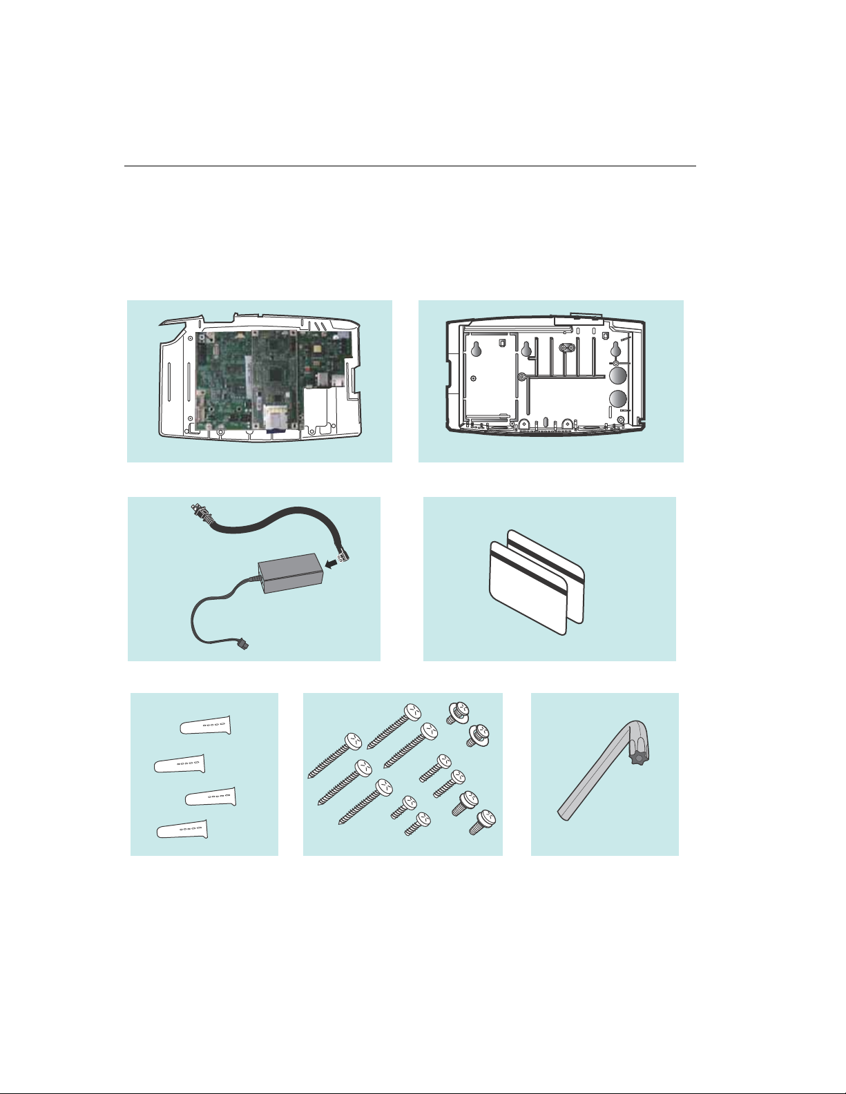
Unpacking the Kronos InTouch
Standard model
TM
10
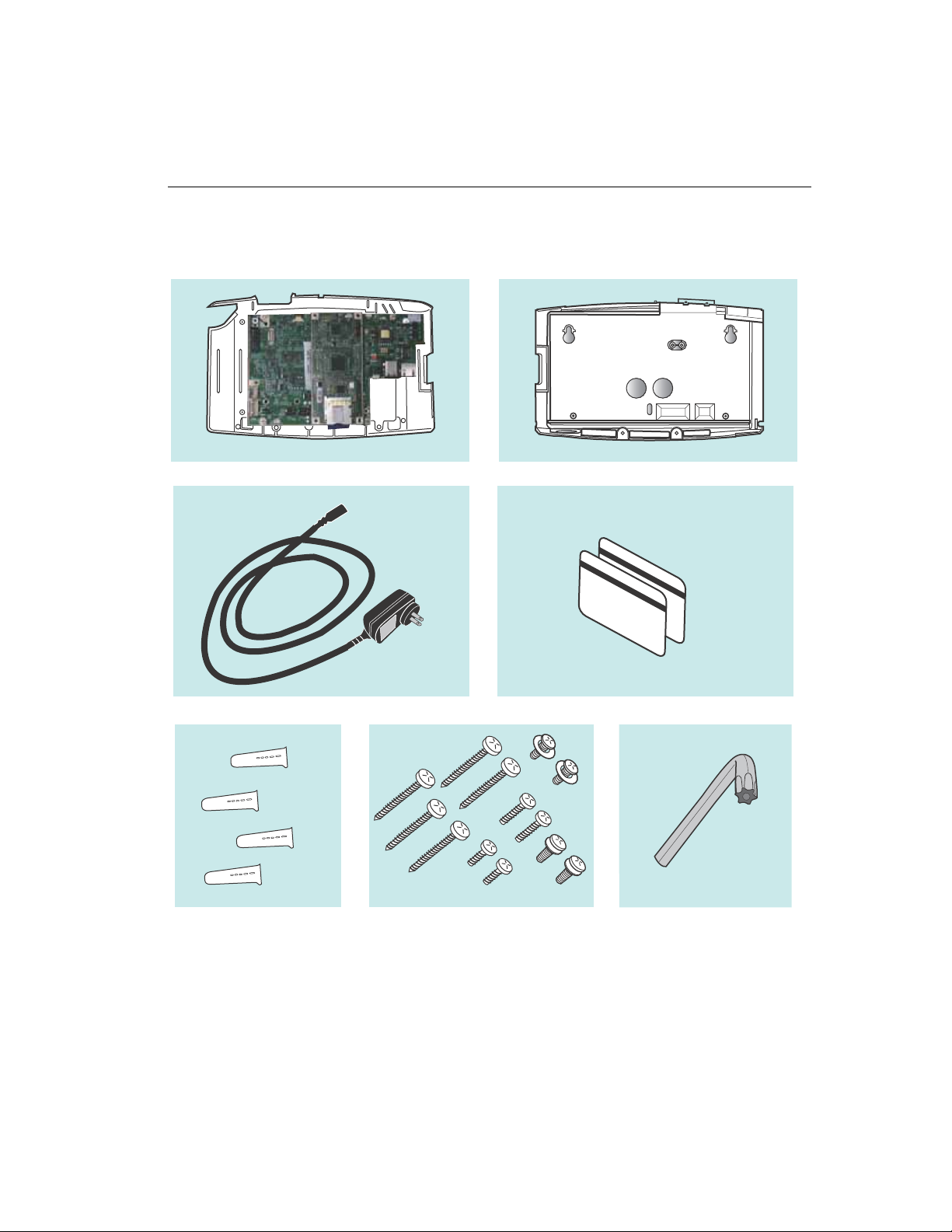
Slim Profile model
Unpacking the Kronos InTouch
TM
Kronos InTouchTM Installation Guide 11

Chapter 1 Before You Install the Kronos InTouch
Notes
• The contents of your kit may vary depending on the model and the options
ordered for your site. For example, the type of transformer and the length of
its power cord may vary depending on the model and your locale.
• Do not remove the cover assembly from its anti-static packaging until you are
ready to install the Kronos InTouch
• A separate plastic bag contains items such as the following:
– Power cord strain relief clip
– Ethernet cord strain relief clip
– Mounting screws
– Plastic anchors for dry wall installation
– A security wrench (for the three torx crews on the enclosure)
–Badges
• Save the paper mounting template and any other printed documents.
TM
TM
.
12
Caution: To avoid damaging the main board, always wear an anti-static wrist
TM
strap when touching the main board of the Kronos InTouch
in any way,
including connecting and disconnecting wires.
Planning the installation
This section describes how to prepare your site for the installation of the Kronos
TM
InTouch
Mounting template
The Kronos InTouchTM kit includes a paper mounting template that you will use to
mark the wall with the following measurements and indicators:
• Where to screw the base cover into the wall
• Where the AC outlet must be located
• Where cables must exit the wall into the Kronos InTouch
• Where cables enter the device from the bottom
.
Planning the installation
TM
Review the following sections to determine how you will use that template to
install the Standard or Slim Profile model Kronos InTouch
Kronos InTouch
TM
at your site.
TM
Installation Guide 13

Chapter 1 Before You Install the Kronos InTouch
Location
• The Kronos InTouchTM is designed for mounting on walls in typical office and
indoor manufacturing environments. Recommended wall surfaces are drywall
(sheetrock) and wood.
• Install the Kronos InTouch
TM
direct sunlight or other high-intensity lighting that could make the screen
difficult to read.
• Ensure that the location for the Kronos InTouch
temperature and humidity ranges:
– Temperature ranges:
Operating: 0 to 40 degrees Celsius (32 to 104 degrees Fahrenheit)
Storage: -20 to +70 degrees Celsius (4 to 158 degrees Fahrenheit)
– Humidity range (operating and storage): 10% to 95% non-condensing
Access
TM
in an area where the screen is not exposed to
TM
falls within the following
14
• New location — To provide optimal access to the Kronos InTouchTM for the
widest range of users, Kronos recommends that the top two mounting screws
be no higher than 54 and 7/8 inches (1.4 meters) above the floor.
• Existing location — If you are replacing an existing Kronos Series 4000
device, you can use the same location (54 and 3/8 inches [1.4 meters] above
the floor) as long as it otherwise conforms to the guidelines and specifications
described in this chapter.
(To remove an installed Kronos Series 4000 device, see
Appendix A,
“Removing a Series 4000 Device,” on page 87.)
• ADA (Americans with Disabilities Act) compliance:
– The 54 and 7/8 inch height specification (1.4 meters) ensures that no part
of the Kronos InTouch
TM
that personnel will physically use (badge reader,
keypad) will be higher than the limit set by the ADA.
– Devices mounted on a wall must not protrude more than 4 inches (10 cm)
from the wall. You must mount the Kronos InTouch
TM
directly to the wall.

– If you are in doubt about any regulations, Kronos recommends that you
Power source
The AC power source must be grounded 100 to 240 VAC, 50/60Hz input voltage.
There are several power options, depending on the model (Standard or Slim
Profile) and the configuration required for your site:
• Standard model — Uses standard AC power from an internal or external
source. It includes an integrated, autosensing, AC power transformer that
supports an IEC C13 external power cord connection. This type of connection
allows the use of compatible international power cords.
Choose from the following power supply methods:
– Mounting over an AC outlet (recommended)
– Mounting with direct AC wiring
– Mounting near an AC outlet
• Slim Profile model — Choose from the following power supply methods:
Planning the installation
check the current ADA requirements.
– Using a power-over-Ethernet cable
– Mounting near an external AC outlet
Adherence to local codes
Installation of the Kronos InTouchTM, including all electrical wiring, must comply
with all applicable national, federal, state, and local safety codes and standards.
TM
Kronos InTouch
Installation Guide 15

Chapter 1 Before You Install the Kronos InTouch
Ethernet cables
• Location — Plan to install the Kronos InTouchTM in a location that allows an
easy and secure connection to an external network (for example, using the
Ethernet cable).
• Ethernet requirements and specifications:
– Your network must comply with the IEEE 802.3AF standard.
– The Kronos InTouch
TM
supports 10BASE-T or 100BASE-T Ethernet
communication and autosensing between 10Mbit and 100Mbit.
– Ethernet communication requires an RJ-45, 8-wire connection, and must
meet all other wiring code specifications.
• All cables must be in place before installing the Kronos InTouch
Optional devices
If you plan to connect certain optional devices to the Kronos InTouchTM, note the
following considerations
TM
TM
.
16
• Some optional devices (remote readers, for example) must be mounted within
a certain number of feet (or meters) of the Kronos InTouch
TM
.
• Some optional devices (for example, the finger scanning option) have
components or cables that must be attached to the Kronos InTouch
TM
before
that device is completely assembled.
Review the instructions in this guide and in the documents that accompany each
optional device.
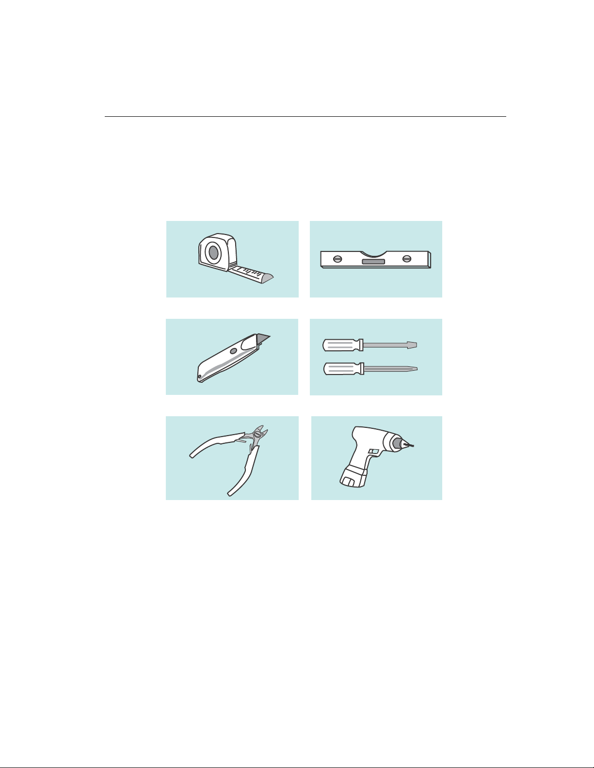
Required tools
In addition to the security wrench that is included with the kit, you will need the
following tools
Required tools
Note:
• Because of the small size of certain screws, Kronos recommends that you use
• The wire cutters should be small as well. For example, a 5-in. flush cutter or a
Kronos InTouch
small screwdrivers (number 1 or 2) with magnetic tips.
circuit board cutter.
TM
Installation Guide 17

Chapter 1 Before You Install the Kronos InTouch
Required Personnel
Depending on the Kronos InTouchTM model that you purchased and the
implementation planned for your site, you will need the following personnel:
• A licensed electrician to install or move AC outlets and power cables
• A qualified person to run Ethernet cable
• One or more qualified installers to assemble the device and mount it on the
wall (a second person may be necessary to hold the front cover while the other
person attaches components to the front and back covers)
• A network administrator or similarly qualified individual to configure device
settings on the Kronos InTouch
Workforce Central software is installed
TM
TM
and on the server where the supporting
18

Configuration settings
After you power up the Kronos InTouchTM, a network administrator or similarly
qualified individual must configure the settings for that device. Those settings
must match the information that the administrator entered on the server using the
device management software.
The device management system administrator’s guide, Kronos InTouch
Guide, and the release notes have all the necessary information.
Next step
Depending on the Kronos InTouchTM model purchased for your site, go to one of
the following chapters to install that device:
Chapter 2, “Installing the Standard Model Kronos InTouch
•
• Chapter 3, “Installing the Slim Profile Kronos InTouch
Configuration settings
TM
User’s
TM
,” on page 21
TM
,” on page 59
Kronos InTouch
TM
Installation Guide 19

Chapter 1 Before You Install the Kronos InTouch
TM
20

Chapter 2
Installing the Standard Model Kronos InTouch
This chapter contains the following sections:
“Prepare the location” on page 22
•
• “Widen the badge reader slot (optional)” on page 29
• “Remove cable access plugs” on page 32
• “Mount the base” on page 33
• “Route the cables” on page 38
• “Install optional devices” on page 40
• “Install the transformer” on page 41
• “Attach the transformer holder and transition board to the base” on page 43
• “Install additional options” on page 45
• “Connect Ethernet cable” on page 46
• “Secure cables with the strain relief clip” on page 49
TM
• “Connect battery, transition board, and transformer cables” on page 52
• “Turn on the power to the device” on page 53
• “Close and lock the Kronos InTouch
Note: If you purchased the Slim Profile Kronos InTouchTM model, go to Chapter
3, “Installing the Slim Profile Kronos InTouchTM,” on page 59.
TM
” on page 55

Chapter 2 Installing the Standard Model Kronos InTouch
TM
Prepare the location
Before you install the Standard model Kronos InTouchTM, complete these steps:
“Step 1: Determine the power source for your site” on page 22
•
• “Step 2: Mark insertion points for the base” on page 24
• “Step 3: Install the AC outlet” on page 28
Step 1: Determine the power source for your site
Before you start the installation, plan with your electrician (if required for the AC
outlet option that you choose) how the Kronos InTouch
outlets at your site.
Choose from the following options and review the associated cautions.
AC outlet options
• Install over an AC outlet (recommended) — If you are replacing a Series
4000 device with the Kronos InTouch
can use the existing AC outlet.
TM
and are using the same location, you
TM
will connect to AC
22
If the installation is at a new location, you will need to install the AC outlet
(requires a licensed electrician) in the location that you mark on the wall with
the mounting template (described in “Step 2: Mark insertion points for the
base” on page 24).
• Install with the internal direct wiring option — You install this separately
orderable option during the Kronos InTouch
TM
installation procedure. “Step 2:
Mark insertion points for the base” on page 24 describes how to mark the
entry point for the power line. You then run the AC power line externally
TM
through conduit into the Kronos InTouch
(requires a licensed electrician).
• Install near an AC outlet
– Use this method if you cannot install the Kronos InTouch
TM
over an AC
outlet or cannot use the internal direct wiring option.

Prepare the location
– Select a location where the distance from the power cable hole at the
bottom of the Kronos InTouch
TM
is not more than 5 feet (1.5 meters) from
the AC outlet.
Note: Installing the device near an AC outlet does not protect against the AC
power cord from being deliberately or inadvertently unplugged from the
outlet.
Cautions
• A licensed electrician must install the AC outlet and associated wiring before
you install the Kronos InTouch
• The AC line that supplies power to the Kronos InTouch
TM
TM
must be equipped
with an appropriate disconnect device (proper fuse or circuit breaker).
• Do not connect the Kronos InTouch
TM
power line to circuits that are being
used for electrical devices that draw large amounts of power, such as air
conditioning units, electrical motors, and compressors.
• Avoid running a communications cable near devices that interfere with data
transmission.
Kronos InTouch
TM
Installation Guide 23
Chapter 2 Installing the Standard Model Kronos InTouch
TM
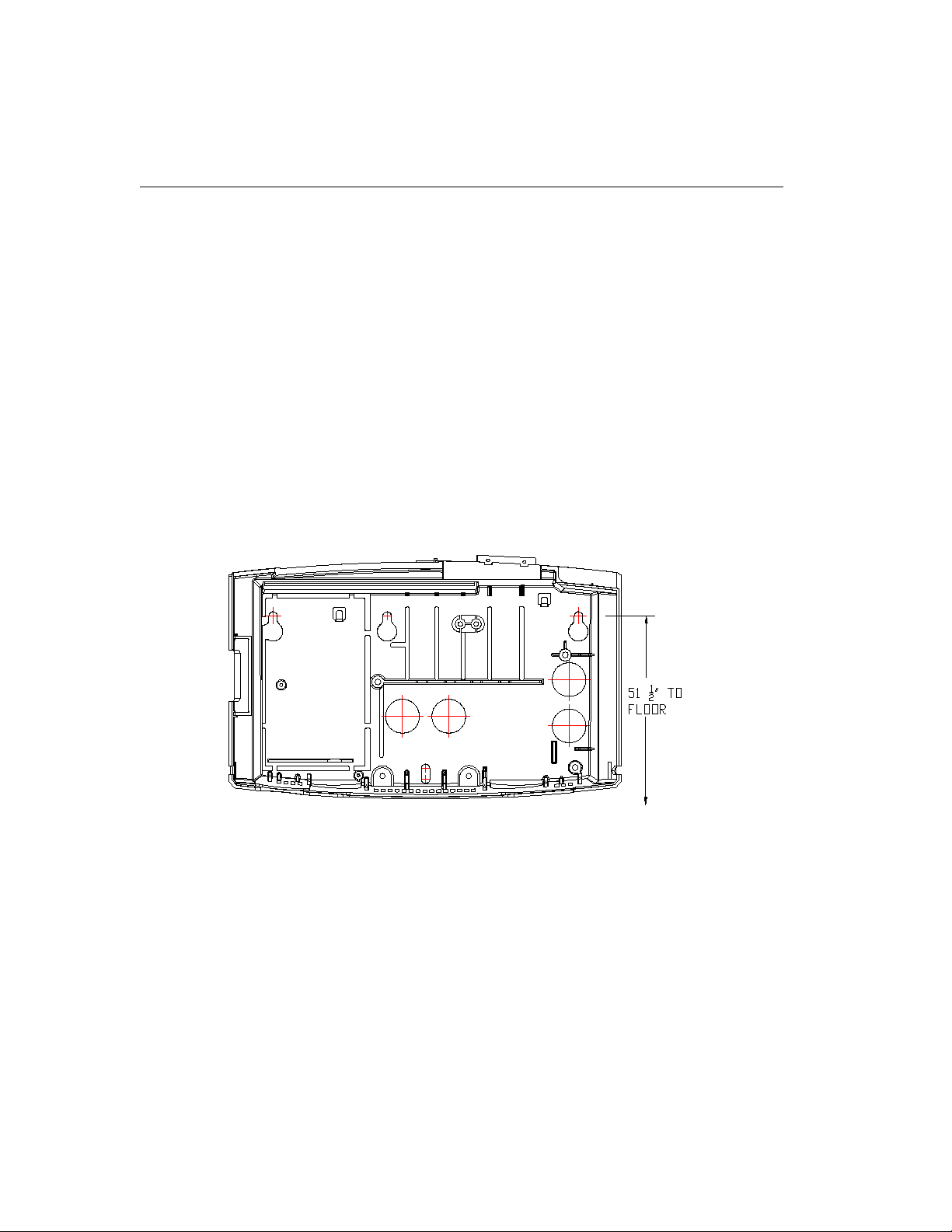
Step 2: Mark insertion points for the base
To mark areas on the wall where you will install the device, use the mounting
template or the base of the device.
Using the mounting template
The mounting template is printed on a sheet of paper that is included with your
TM
Kronos InTouch
plan to install the Kronos InTouch
Note that you use the same template for both models: the two large holes in the
middle are for the Slim Profile model and the two large holes on the right are for
the Standard model.
kit. Use that template to mark the areas of the wall where you
TM
.
24
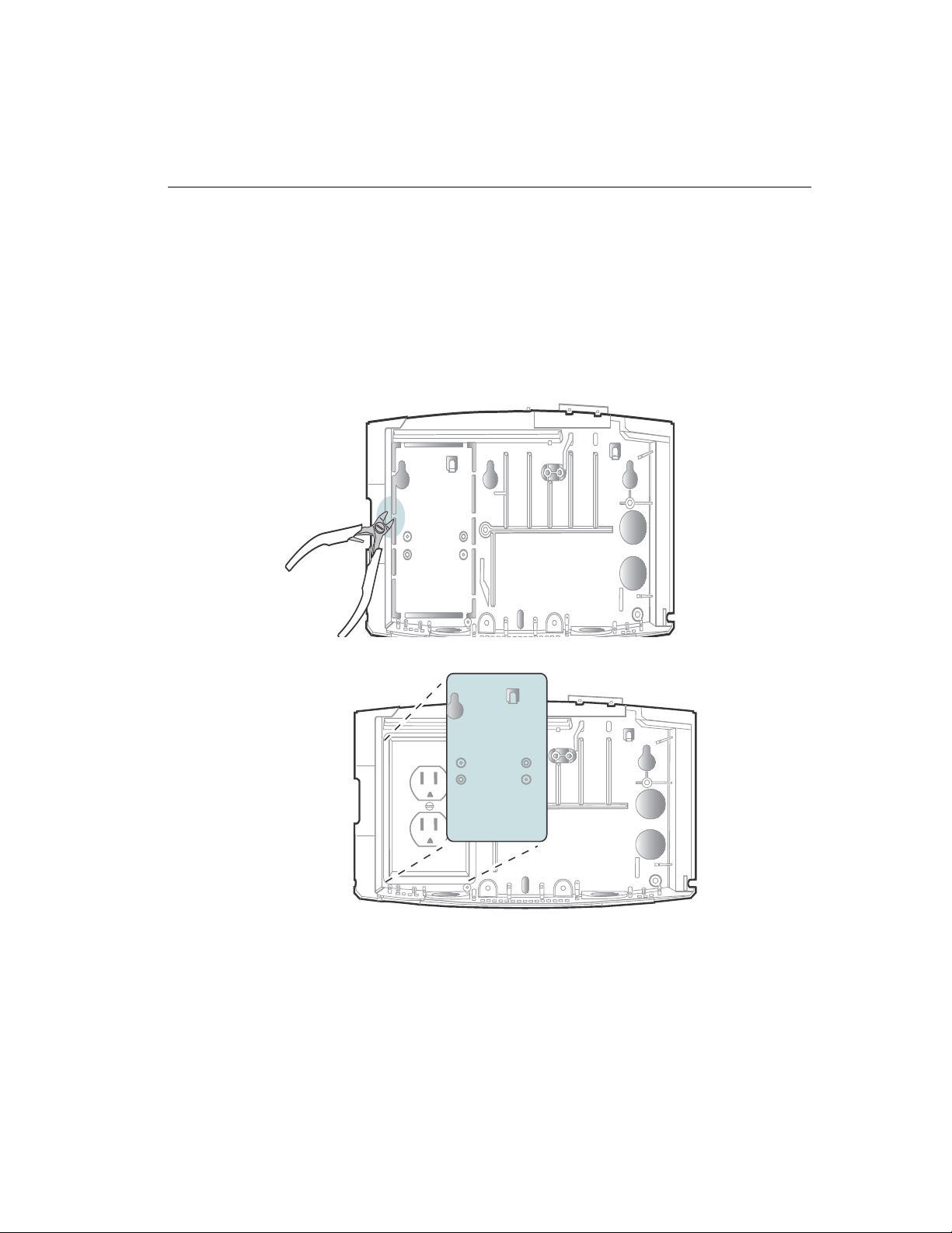
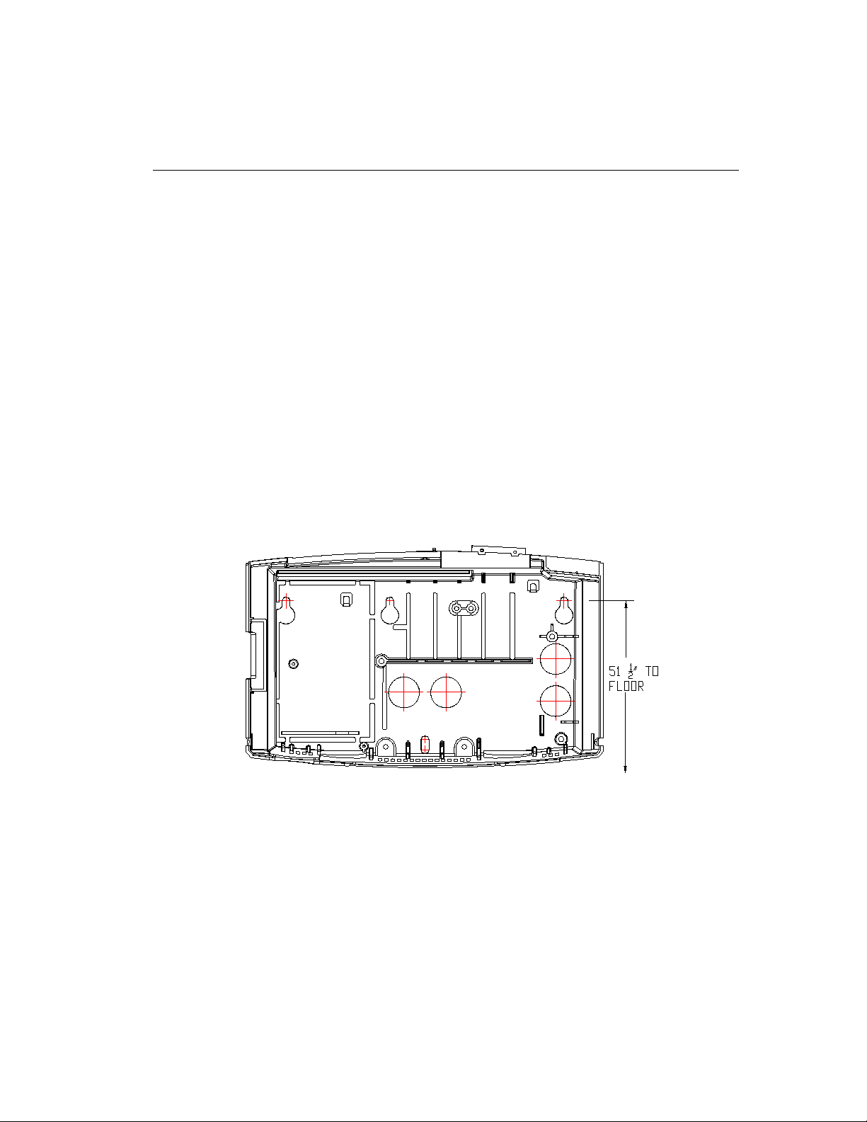
Using the base of the device as the template
You can also use the base of the Kronos InTouch
however, that if you plan to install the device over the AC outlet, first remove the
plastic knockout plate from the base of the Kronos InTouch
base to fit over the outlet as you hold the base against the wall.
1. Use a small wire cutters to cut the plastic tabs that anchor the knockout:
Prepare the location
TM
as the template. Note,
TM
. This will allow the
2. Remove the plate:
Kronos InTouch
TM
Installation Guide 25

Chapter 2 Installing the Standard Model Kronos InTouch
Marking the wall
1. Tape the mounting template (or position the base) at the optimal height and
TM
location for the Kronos InTouch
.
– The top mounting screws must be 51 and 1/2 inches (1.3 meters) above
the floor, for ADA compliance.
– Use a level to ensure that the top of the template is horizontal to the floor.
Note: If you are replacing a Series 4000 device, you can install the Kronos
InTouch
TM
on the same area of the wall but you cannot use the same screw
holes.
2. If installing over an AC outlet (Standard model only), mark the location for
the installation of that outlet. (If you are replacing a Series 4000 device that
was previously mounted over an AC outlet, you can use that same outlet for
TM
the Kronos InTouch
.)
3. Mark the location of the mounting screw holes, as follows
– Installing over an AC outlet: Mark the two top screws to the right of the
knockout plate and the single screw in the bottom middle. (See the
illustration in
“Example 1: Mounting over an AC outlet:” on page 35.)
TM
26
– Installing near an AC outlet: Mark the top screw that is on the far left (on
the knockout plate), the top screw on the far right, and the single screw in
the bottom middle. (See the illustration in “Example 3: Mounting near an
AC outlet:” on page 37.)
– Installing with direct AC wiring: Mark the top screw that is on the far left
(on the knockout plate), the top screw on the far right, and the single
screw in the bottom middle. (See the illustration in “Example 2:
Mounting with direct AC wiring” on page 36.)
4. If you plan to run an AC power line externally through conduit to the internal
direct wired option inside the Kronos InTouch
TM
, mark the point of entry into
the bottom left hole of the base, as indicated on the template. (See the
illustration in “Example 2: Mounting with direct AC wiring” on page 36.)
5. If you plan to run an Ethernet cable or cable from a remote reader through the
wall to enter the Kronos InTouch
TM
from the back or through the bottom, use

Prepare the location
the template to mark the point of entry. (See the illustrations in “Securing the
Ethernet cable” on page 39.)
6. If you are installing the Kronos InTouch
TM
near an AC outlet, be sure the
outlet is within 5 feet (1.5 meters) of the template.
7. After you finish marking all entry points, screw holes, etc., remove the
mounting template (or base) from the wall.
Kronos InTouch
TM
Installation Guide 27

Chapter 2 Installing the Standard Model Kronos InTouch
Step 3: Install the AC outlet
If you plan to install near an existing AC outlet, skip this step.
• To install over an AC outlet:
a. Be sure you have prepared the location and reviewed the cautions
described in
22.
b. Use a licensed electrician to install the AC outlet at the location that you
marked on the wall in “Step 2: Mark insertion points for the base” on page
24.
• To install with the internal direct wiring option, use a licensed electrician to
run the power line (CL-2 code or higher) through conduit up to the point of
entry that you marked on the wall in “Step 2: Mark insertion points for the
base” on page 24.
Warning: Do not turn on the power for the direct wiring option until until you
are directed to do so in this guide or in the installation guide for that option
kit.
“Step 1: Determine the power source for your site” on page
TM
28
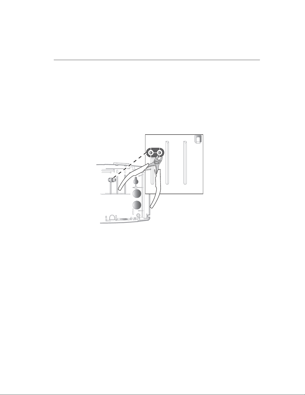
Widen the badge reader slot (optional)
Widen the badge reader slot (optional)
If the badges that you will use with the Kronos InTouchTM are more than 0.05 in
(1.27 mm) thick, you need to install two spacers in the badge reader (card or mag)
to accommodate the badges. The spacers are molded into the base of the Kronos
TM
InTouch
1. Use a wire cutters to remove the spacers from the base.
.
Kronos InTouch
TM
Installation Guide 29
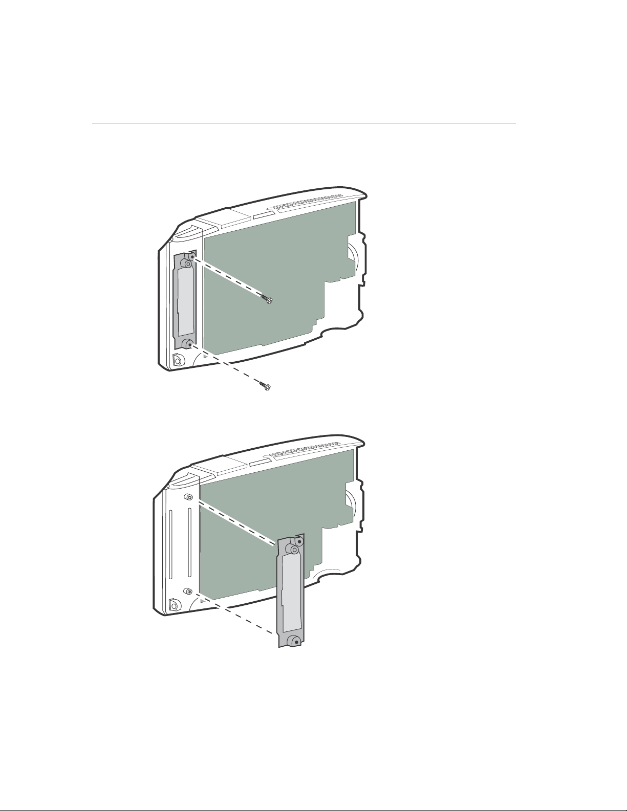
Chapter 2 Installing the Standard Model Kronos InTouch
2. On the inside of the front cover, use a Phillips screwdriver to loosen the two
screws that hold the badge reader cover in place.
TM
30
3. Remove the badge cover.
 Loading...