


The KRONNER SIDE-KICK
A uterine manipulator Holder
for holding the Arch Koh uterine manipulator*
Instructions for use
* Model UMH 67, manufactured by CooperSurgical
United States Patent 8,485,484.B2

1
The Kronner SIDE-KICK is a uterine
manipulator Holder which firmly holds
the Arch Koh and other uterine manipulators during laparoscopic surgery on
female pelvic organs. The Side-Kick
does not interfere with re-positioning
the uterus with the attached manipulator.
The Side-Kick Rail Grip is attached to
either side rail of the operating table. It
is placed behind the attachment for the
leg stirrup.
The manipulator is inserted into the
patient using standard technique, then
the Side-Kick is joined to it.
With proper adapters the Side-Kick
may be used with other manipulators,
such as the RUMI, and the V-Care*.
A gas supply module, which is also
attached to the rail of the operating
table, transfers nitrogen or compressed
air from the wall or a portable tank to
the Side-Kick through two flexible lines.
When the switch is turned off the SideKick joints are decompressed.
Pressing a foot pedal, that is
connected to the gas supply module,
releases all the Side-Kick joints for
position changes. When the foot pedal
is released the joints lock.
A branched gas line connects the
supply module to two luers of the arm
assembly. A single gas line joins the
gas supply module to the main pivot.
Only the arm components and
adapters are pre-vac sterilized. The
disposable gas lines are supplied
sterile.
The KRONNER SIDE-KICK
A uterine manipulator Holder
Richard F. Kronner MD FACS
*See V-Care literature for required components.
Intended use:
The Kronner Side-Kick Uterine/vaginal Manipulator Holder is intended to assist the
surgical staff in mounting, positioning and holding a uterine manipulator during
gynecological laparoscopic surgical procedures. It is intended for use by trained
operating room personnel in an operating room environment.
"Caution: Federal law restricts this device to sale by or on the order of a physician.”
A description of the device and the intended use.

2
Indications for use:
The Kronner Side-Kick Uterine Manipulator Holder is intended to assist the surgical
staff in mounting, positioning and holding a uterine manipulator during gynecological
laparoscopic surgical procedures. It is intended for use by trained operating room
personnel in an operating room environment.
Contraindications:
1. Adapter unavailable for chosen manipulator
2. Table rail unreliable
3. Gas supply is unreliable or unavailable at required pressure
4. Intended surgery does not require use of a uterine or vaginal manipulator.
See the uterine manipulator manufacturers’ literature regarding instruction
for use, indications, contraindications and safety information.
Warnings:
1. Do not use with pressure greater than 150 psi.
2. Do not detach the gas supply module from the gas supply while the manipulator is attached.
3. Do not shut off the gas supply module switch while the manipulator is attached.
4. Do not use substitute flexible gas lines.
5. Do not use if gas leaks are detected.
6. Use only the specified adapter with the chosen manipulator.
7. On older operating tables with motorized perineal rests make sure the rest is in the down
position before adding the main pivot and the remainder of the assembly.
8. The gas module switch must be in the “on” position during use.
9. Do not use the sterile lines if the package is damaged or the 3 year expiration date is passed.
10. Do not attach the holder to a manipulator of a patient that is not under anesthesia or otherwise
immobilized.
11. Use only nitrogen or compressed air gas.
12. In the event the Side-Kick was disassembled without turning off the gas module switch, the
pneumatic joints may still be pressurized. To decompress, attach a male luer from a
branched gas line with one short branch disconnected, or use a syringe with the plunger
removed.
13. Do not attach the Sidekick rail grip over an attachment of the table rail to the table.
14. Attach the single gas line to the pivot and the branched line to the arm.
15. Remove the Sidekick arm before raising the lower end of the operating table.
16. Do not attach a gas line to a uterine manipulator, extreme danger.
Precautions:
1. Verify that the operating table rail is not loose.
2. Verify that the operating table end can be lowered or removed.
3. Restrain the patient from sliding on the table when the table is tilted.
4. Prevent the gas supply line from damage due to moving objects.
5. Check the uterine manipulator for defects.
6. Verify that the gas supply is steady and available at 140-150 psi.
7. Securely attach all flexible gas lines to the gas supply module and to the holder.
8. Read the instruction manual prior to use.
9. When making a patient transfer to or from the operating table to a cart with Sidekick in between
remove Sidekick or protect it from the cart.
10. Always support a connected manipulator when stepping on the gas pedal.

3
COMPONENTS
pneumatically
locking ball joint
Arch-Koh
Uterine manipulator
Telescopic Arm,
pneumatically locking
Gas Lines from
supply module
Arm connection
Main Pivot,
pneumatically locking
Rail Grip
Operating Table Rail
Connector
Adapter
Adapter ball grip
Cross Rod
Holder assembly
Outer arm
Inner rod
GAS LINES
patient and table not shown
supplied sterile,
shelf life 3 years,
see package label

4
GAS SUPPLY MODULE
to foot pedal
connection for
wall gas supply
knob for Rail
attachment
luers for gas lines
on/off switch
supply
gas line
supply line
release
for table rail
safety pressure release
luer guard
activation
foot pedal
press to
disconnec
t

1. After sterilization, insert the inner rod into the outer arm.
2. If resistance is met, gas pressure may not have been released after the last use.
Attach a male luer from a branched gas line with one short branch disconnected,
or use a syringe with the plunger removed.
STERILIZABLE COMPONENTS
Joining the inner rod to the arm.
5
luer
luer
outer arm
inner rod
1. Join the components so
the ball of the shaft is
directed away from the flat
surface of the grip marked
“UP”.
2. Position the manipulator
joining screw so the
adapter can be joined to
the manipulator.
Assembling the Arch Koh adapter components
engraved
“UP”
shaft
joining
screw
Assembled wrong
engraved
“UP”
Outer arm, inner rod and uterine manipulator adapter.
6
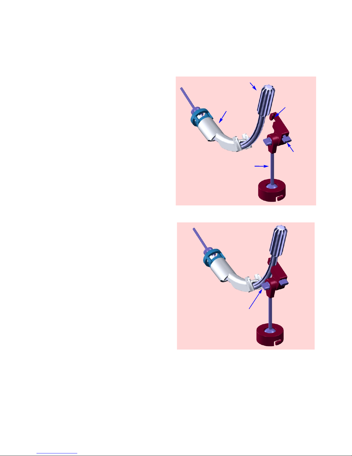
1. Retract the joining screw so the
Arch Koh can be slid into the
adapter recess.
2. With the ball joint shaft directed
downward, slide the Arch Koh into
the recess. This connection is
made just below the Arch Koh
handle.
This step can be performed before
or after patient insertion.
adapter
recess
1752-2
joining
screw
ball joint shaft
5905 angle
adjustment
screw
If necessary, release the angle
adjustment screw and set the joint
so the ball joint shaft is directed
downward. This will set the
connection to the Side-Kick arm with
the maximum potential range for
uterine positioning.
3. Tighten the joining screw.
Joining the ARCH KOH to the adapter
Arch Koh
handle

1. Attach the gas supply module to
the rail of the operating table at a
position where the flexible gas lines
will reach to the Side-Kick gas line
connections. Usually this is just
beside the planned position for the
Side-Kick rail grip.
Whenever possible attach the gas
module to the side of the table not
used for patient transfer.
2. Turn off the on-off module
switch. This will prevent gas from
leaking from the luer connections
prior to flexible gas line connection.
3. Connect the gas line to the
hospital nitrogen* or compressed
air supply.
4. Set the supply to 130-150 PSI.
5. Position the attached foot pedal.
(Note that it cannot be disconnected from
the supply module.)
*
not nitrous oxide
7
Setting up the Gas Supply Module
NON-STERILE COMPONENTS
to foot pedal
knob for Rail
attachment
luers for gas lines
on/off switch
supply
gas line
supply line
release
for table
rail
safety
pressure
release
luer guard
Gas supply module, foot pedal assembly, main pivot, rail grip
activation
foot pedal
press to
disconnec
t

8
The rail grip assembly can be placed on either rail
behind the attachment for the leg stirrup.
1. Rotate the rail grip handle counter-clockwise until the bottom
of the lower rail grip aligns with the index mark.
This setting will allow the rail grip assembly to be attached by
tilting it outward.
In order to attach it without tilting, more counterclockwise rotations
are required.
index mark
lower
rail grip
4. Rotate the handle clockwise until it is tight, approximately
three full rotations.
Be sure the assembly is hanging straight downward in both
planes during this step and the rail grip upper notch is touching
the rail on both sides of the rail grip.
2. Select a position, on the rail, that will place the Holder arm
directly below the manipulator.*
3. Tilt the assembly outward and set it on the rail. Pivot it toward
the rail until the lower rail grip is below the rail.
Corrections can be made later by repositioning the main pivot
assembly.*
The rail grip can be released and slid on the rail to re-position if
necessary.*
*
The design of the Holder allows for variability in these settings.
Attaching the Rail Grip assembly to the
operating table rail.
lower
rail grip
table rail
When placing the Sidekick
Rail Grip onto the table rail,
do not put it over the rail table
attachment or a table rail notch.
Placing it in these areas could
cause an unstable attachment.
Table rail notches
Rail table attachment
Sidekick rail grip

4. Slide the main pivot until
the arm connection is located
below the planned connection
to the manipulator.
5. Firmly tighten the T-handle
clockwise.
This setting can be changed
later, if needed.
1. Rotate the T-handle
counter-clockwise to a stop
to open the connection joint
for the main pivot cross rod.
2. Position the main pivot and
cross rod so “UP” is positioned
upward.
Attaching the main pivot assembly
to the connector of the rail grip assembly
3. Insert the cross rod into the
connection joint.
fully open
Main pivot
Arm connection
T-handle
9
connector
T-handle
Main Pivot
“UP”
cross rod

1. Rotate the main pivot handle
counter-clockwise to a stop to
open the attachment joint.
3. Tighten the main pivot handle
clockwise.
Stops prevent the arm from falling
prior to pressurizing the system.
Do NOT overcome these stops.
4. Lower the arm sideways to
one of the stops or continue to
hold it during the next steps.
Attaching the arm to the main pivot
2. Insert the arm assembly into
the attachment joint until the telescoping inner rod will allow for the
required manipulator movement.
This setting can be changed later,
if necessary.
10
Arm attachment joint
Arm assembly

11
Warning: Do not attach a gas line to a uterine manipulator, extreme danger.
Attaching the gas lines
1. Connect the single gas line to
the main pivot luer.
2. Connect the other end of the
single gas line to one of the gas
output luers of the supply module.
4. Connect the other end to the
remaining luer of the supply module.
3. Connect the branched line to
the two luers of the arm assembly.
luer
luer
luer
Firmly tighten all gas line luer connections.
luer
Note: The gas line connections to the arm may be made prior to joining the arm to
the main pivot assembly.
The single gas line may be connected to the pivot and the supply module prior to
arm attachment.
To avoid confusion, make these connctions prior to inserting the manipulator into
the patient.

12
Attaching the adapter with manipulator to the Holder
Turning the gas on
1. Insert the Arch Koh into a properly
anesthetized and restrained patient.
2. Connect the adapter ball grip to the arm by
sliding the two notches over the arm pins and
rotating the adapter clockwise. Gas pressure
must be off during this step.
notch
pin
1. Grasp the manipulator.
2. Press the foot pedal to re-position the attached manipulator.
3. After releasing the foot pedal, allow gas pressure to build prior to releasing
the manipulator.
To use the Holder
1. Turn the supply module
switch on.
View 1
View 2
adapter ball grip
“OFF”
“ON”
Support the arm until the gas is turned on.

13
1. Support the arm
2. Turn off the gas module switch prior to disconnecting the gas lines. This will
decompress the holder joints.
3. Detach the Side-Kick adapter from the manipulator, reverse steps 1-3 page 6
entitled: “Joining ARCH KOH to the adapter” or detach the adapter and
manipulator from the arm. Reverse step 2 page 12 entitled “Attaching the
adapter with manipulator to the Holder”
4. Remove the manipulator following instructions from the manufacturer.
5. Disassemble Side-Kick by reversing the assembly steps.
6. Remove the Sidekick arm before raising the lower end of the operating
table.
Removing Sidekick
Problems with Sidekick
In the rare event Side-Kick interferes with required uterine manipulation or fails
to hold the uterine manipulator, the uterine manipulator should be disconnected
from Side-Kick. Reverse steps 1 to 3, page 6 (Joining the ARCH KOH to the
adapter)
If necessary, the arm can be detached from the main pivot. Reverse steps1 to 3
page 10. (Attaching the arm to the main pivot).

14
Cleaning Components
of the
Kronner Side-Kick
a uterine manipulator holder
Manual Cleaning:
1. Remove the inner rod from the outer arm.
2. Disconnect the manipulator adapter from the inner rod assembly at the ball joint and
remove the manipulator joining screw from the manipulator adapter, see pg. 7.
3. Inspect parts for defects, such as parts not fitting together or misshapen parts.
Contact Sidekick sales reps. regarding defects.
4. Use Enzol® enzymatic detergent, and prepare according to the manufacture’s recommendations
of 1 oz. per gallon of warm tap water, (or FDA approved equivalent)
5. Soak the outer arm, inner rod and adapter for five minutes in the prepared solution.
6. Maneuver movable parts to loosen trapped soil. Use a soft bristled brush (M16) to gently
scrub to remove any visible soil and actuate all moveable parts while scrubbing in order to loosen
trapped soil. Use an appropriate size lumen brush (45-541) for internal channels.
7. Repeat steps 5 and 6 two additional times for a total of three times.
8. Prepare a tap water bath at 38-49º C.
9. Agitate the assembly by hand for a minimum of one minute in the prepared bath.
10. Rinse the assembly under running tap water for at least one minute.
11. Dry the exterior of the assembly with a clean, lint free cloth.
The rail grip, main pivot assembly,
gas supply module with foot pedal are not sterilized.
Cleaning the sterilizable components:
Outer arm, inner rod, adapter

15
Sterilizing Components
of the
Kronner Side-Kick
a uterine manipulator holder
Sterilizing the Outer arm, inner rod, and adapter:
1. Place items in the Kronner Sterilizer tray as illustrated
2. Sterilization wrap : Kimgard KC400 (or FDA approved equivalent)
3. Pre-vacuum temperature: 270 F, (132C)
4. Exposure time: 4.0 minutes
5. Drying time: 45 minutes

16
Kronner Medical
1443 Upper Cleveland Rapids Road
Roseburg, Oregon 97471
Phone: (800) 706-3533 or (541) 672-2543
Fax: (541) 672-1074
E-mail: kronner@rosenet.net
The Kronner Side-Kick
A uterine manipulator Holder
Parts List for the Arch Koh instrument holder
KSK-5000 includes:
1. 5100-5150-5200 Rail grip and connector assembly
2. 5300 Main pivot assembly
3. 5700-5800 Pneumatic foot pedal and Gas supply module
4. 1120 Gas supply hose (includes one DISS fitting)
5. 5400 Outer Arm assembly
6. 5500 Inner rod with pneumatically locking ball joint
Required adapter
1. 5900 Arch Koh manipulator adapter
Replacement parts for the adapter
1. 5905 Arch Koh adapter angle adjustment screw
2. 5906 Arch Koh joining screw
Disposable components, provided sterile,
(one set required for each procedure)
1. HPL1-BL1-V2 Branched gas line set, contains:
a. Branched line with two male luer-lock fittings on the distal
end and one luer-lock female fitting with a luer activated valve
on the proximal end, length: 96 inches.
b. Straight gas line, with one male luer-lock fitting on the
distal end and one luer-lock female fitting with a luer activated
valve on the proximal end, length: 96 inches.
c. Shelf life: 3 years
 Loading...