

Page 1

<v>T-Typ1</v>
Swadro 807
<v>T-Typ2</v>
Swadro 809
<v>T-Typ3</v>
Swadro 810
<v>T-Typ4</v>
Swadro 907
Rotary Swather
</v>
</v>
</v>
</v>
<v>T-Typ6</v></v>
<v>T-Typ7</v></v>
<v>T-Typ8</v></v>
<v>T-Typ9</v></v>
<v>T-Typ5</v></v>
(
<v>T-abMasch.-Nr.</v>
from serial no.
<v>T-Bestell-Nr.</v>
Order no.
</v>
: 150 000 030 06 en
</v>
: 829 360)
<v>T-Typ10</v></v>
Or i g i n a l o p e r a t i n g i n s t r u c t io n s
<v>B-Titelbild</v> </v>
19.08.2011
Page 2

Table of Contents
Pos:1/BA /Konformitätserklärungen/Schwader/N euab2 010/Swadro807_809_81 0_907@ 75\mod_1309416177020_78.doc @662790
CV0
EC Declaration of Conformity
We Maschinenfabrik Bernard Krone GmbH
Heinrich-Krone-Str. 10, D-48480 Spelle, Germany
hereby declare as manufacturer of the product named below, on our sole responsibility,
that the
Machine: Rotary rake KRONE
Type / types: Swadro 807, Swadro 809, Swadro 810, Swadro 907
to which this declaration refers is in compliance with the relevant provisions of
EC directive 2006/42/EC (machines).
The signing Managing Director is authorised to compile the technical documents.
Spelle, 18.08.2011
Dr.-Ing. Josef Horstmann
(Managing Director, Design and Development)
Year of manufacture: Machine No.:
Pos:2/BA /Vorwort/Sehrgeehrter Kunde@ 0\mod_11956263003 26_78.doc@ 905
Dear customer,
Dear customer,
You have now received the operating instructions for the KRONE
product which you have purchased.
These operating instructions contain important information for the
proper use and safe operation of the machine.
If these operating instructions should become wholly or partially
unusable, you can obtain replacement operating instructions for
your machine by stating the number given overleaf.
Pos:3/BA /-----Seitenumbruch------ @0\mod_1196175311 226_0.doc@ 4165
2
Page 3

Table of Contents
Pos:4/BA /Inhaltsverzeichnis@ 0\mod_1196861555655 _78.doc@ 15165
1 Table of Contents
1 Table of Contents...................................................................................................................................3
2 Foreword .................................................................................................................................................6
3 Introduction.............................................................................................................................................7
3.1 Purpose of Use.................................................................................................................................. 7
3.2 Validity............................................................................................................................................... 7
3.3 Identification Plate .............................................................................................................................7
3.4 Information Required for Questions and Orders................................................................................ 8
3.5 Intended Use .....................................................................................................................................9
3.6 Technical data ...................................................................................................................................9
4 Safety.....................................................................................................................................................14
4.1 Introduction...................................................................................................................................... 14
4.2 Identification of the hazard warnings............................................................................................... 14
4.2.1 Re-Ordering the Adhesive Safety and Information Labels..........................................................15
4.2.2 Affixing the Adhesive Safety and Information Labels..................................................................15
4.2.3 Contact......................................................................................................................................... 15
4.3 Position of the Adhesive Safety Stickers on the Machine............................................................... 16
4.4 Position of the General Information Labels on the Machine............................................................ 18
4.5 Identifying Symbols in the Operating Instructions ........................................................................... 19
4.6 Identification of the hazard warnings............................................................................................... 19
4.6.1 Personnel Qualification and Training Fehler! Textmarke nicht definiert...................................... 20
4.6.2 Dangers in Case of Non-compliance with the Safety Instructions............................................... 20
4.6.3 Safety-conscious work practices .................................................................................................20
4.7 Safety Instructions and Accident Prevention Regulations............................................................... 21
4.8 Hitched Implements.........................................................................................................................22
4.9 PTO operation .................................................................................................................................23
4.10 Hydraulic system .............................................................................................................................24
4.11 Tyres................................................................................................................................................ 24
4.12 Maintenance ....................................................................................................................................25
4.13 Working in the vicinity of power transmission lines ......................................................................... 26
4.14 Unauthorised Conversion/Modification and Spare Parts Production ..............................................26
4.15 Inadmissible Modes of Operation.................................................................................................... 26
4.16 Safety Instructions on the Machine ................................................................................................. 26
5 Commissioning.....................................................................................................................................27
5.1 First installation................................................................................................................................ 27
5.2 Preparations on tractor....................................................................................................................28
5.2.1 Adjusting the lower suspension arms.......................................................................................... 28
5.3 PTO shaft......................................................................................................................................... 29
5.3.1 Length adjustment .......................................................................................................................29
3
Page 4

Table of Contents
5.4 Height of tractor lower suspension arms.........................................................................................30
6 Start-up..................................................................................................................................................31
6.1 Mounting onto the Tractor................................................................................................................ 31
6.2 Hydraulics........................................................................................................................................ 32
6.2.1 Special Safety Instructions ..........................................................................................................32
6.2.2 Connecting the hydraulic lines..................................................................................................... 33
6.3 Lighting connection.......................................................................................................................... 34
6.4 Connecting the electrical controls.................................................................................................... 35
6.5 Install the PTO shaft........................................................................................................................ 36
7 Driving and Transport..........................................................................................................................37
8 Operation...............................................................................................................................................39
8.1 Overload protection .........................................................................................................................39
8.2 From transport into working position ............................................................................................... 40
8.3 Removing the tine protections from the tine tips ............................................................................. 40
8.4 Lowering the rotor arms into working position.................................................................................40
8.5 Adjusting the Rear Swath Cloth....................................................................................................... 41
8.5.1 Height adjustment of the swath former........................................................................................ 42
8.6 Adjusting the Front Swath Cloth (Swadro 810) ............................................................................... 42
8.7 Adjusting the Rear Swath Cloth (Swadro 907)................................................................................44
8.7.1 Adjusting the swath former lengthwise........................................................................................ 45
8.7.2 Height adjustment of the swath former........................................................................................ 45
8.8 Swivel tine arms to working position................................................................................................ 46
8.8.1 For design with collapsible tine arm ............................................................................................ 47
8.9 Move the hoop guards to the working position................................................................................ 48
8.10 Adjusting the raking height mechanically ........................................................................................ 49
8.10.1 Adjusting the raking height - electrically (optional for Swadro 810, Swadro 907) ................... 50
8.10.2 Function of switches on the control unit (optional for Swadro 810, Swadro 907) ................... 50
8.11 Travelling on an incline.................................................................................................................... 52
8.12 Travelling speed und drive speed.................................................................................................... 52
8.13 Switching from working position to transport position .....................................................................53
8.14 Move the hoop guards to transport position....................................................................................53
8.15 Swivelling tine arms into transport position ..................................................................................... 54
8.15.1 With rigid tine arms design ...................................................................................................... 54
8.15.2 For design with collapsible tine arm ........................................................................................ 55
8.16 Pushing the Swath Cloth into Transport Position............................................................................56
8.17 Pushing the Swath Cloth into Transport Position............................................................................57
8.18 Raising the Rotor Arms to Transport Position.................................................................................58
8.19 Protecting the Tine Tips (Transport Position and Swather Switched Off)....................................... 58
8.20 Switching from One Side Swath to Two Individual Swaths............................................................. 59
8.21 Switching from Two Individual Swaths to One Side Swath (Swadro 810) ...................................... 60
4
Page 5

Table of Contents
8.22 Parking.............................................................................................................................................61
9 Settings .................................................................................................................................................62
9.1 To adjust the rotor running gear...................................................................................................... 62
9.2 Regulating direction of travel...........................................................................................................63
9.3 Adjustable throttles .......................................................................................................................... 64
10 Maintenance..........................................................................................................................................65
10.1 Special Safety Instructions ..............................................................................................................65
10.2 Compensation Spring(s)..................................................................................................................65
10.3 Test run............................................................................................................................................65
10.4 Tightening Torques..........................................................................................................................66
10.5 Tightening Torques (Countersunk Screws)..................................................................................... 67
10.6 Testing the screws on the tines.......................................................................................................67
10.7 Tyres................................................................................................................................................ 68
10.7.1 Checking and maintaining tyres...............................................................................................68
10.7.2 Torque of wheels on the running gear.....................................................................................69
10.7.3 Tyre air pressure......................................................................................................................69
10.8 Replacing the tine arms(in case of repair).......................................................................................70
10.9 Replacing the tine arms(in case of repair).......................................................................................72
11 Maintenance – lubrication chart .........................................................................................................74
11.1 Special Safety Instructions ..............................................................................................................74
11.2 PTO shaft.........................................................................................................................................75
12 Maintenance – lubrication chart .........................................................................................................76
12.1 Lubrication Chart .............................................................................................................................77
13 Maintenance - hydraulic system.........................................................................................................79
14 Maintenance - Gearbox........................................................................................................................80
14.1 Filling Quantities and Lubrication Designations for Gearboxes....................................................... 80
14.2 Rotor gear / rotor housing................................................................................................................ 80
14.3 Transfer gearbox front and rear....................................................................................................... 81
15 Special equipment................................................................................................................................82
15.1 Tine loss safeguard .........................................................................................................................82
15.2 Chain for height restriction of suspension arms .............................................................................. 83
16 Placing in Storage................................................................................................................................84
16.1 Special Safety Instructions ..............................................................................................................84
16.2 At the End of the Harvest Season................................................................................................... 85
16.3 Before the Start of the New Season................................................................................................86
16.4 Special Safety Instructions ..............................................................................................................86
17 Malfunctions - Causes and Remedies................................................................................................87
17.1 Special Safety Instructions ..............................................................................................................87
18 Appendix ...............................................................................................................................................89
Pos:5/BA /-----Seitenumbruch------ @0\mod_1196175311 226_0.doc@ 4165
5
Page 6

Foreword
Pos:6.1/Ü berschriften/Überschriften 1/U-Z/Vorwort@ 0\mod_1195627720123 _78.doc@9 82
2 Foreword
Pos:6.2/ BA/Vorwort/Schwader/Verehrter KundeSchwad er@1\m od_1202129116819_78.doc @57456
Dear Customer,
By purchasing your rotary rake, you have acquired a quality product from KRONE.
We are grateful for the confidence you have invested in us in buying this machine.
It is important to read the operating instructions very carefully before you start operating the
machine to allow you to use the rotary rake to its full capacity.
The contents of this manual are laid out in such a way that you should be able to perform any
task by following the instructions step by step. It contains extensive notes and information about
maintenance, how to use the machine safely, secure working methods, special precautionary
measures and available accessories. This information and these instructions are essential,
important and useful for the operational safety, reliability and durability of the rotary rake.
Pos:6.3/ BA/Vorwort/Schwader/Weiterer VerlaufSchw ader@1\ mod_1202129119147_78.doc @57476
Note
In the operating instructions which follow, the rotary rake will also be referred to as the
"machine".
Pos:6.4/ BA/Vorwort/BeachtenSie fürMasc hine@ 0\mod_1195626904076_78.doc @944
Please note:
Pos:7/BA /-----Seitenumbruch------ @0\mod_1196175311 226_0.doc@ 4165
The operating instructions are part of your machine.
Only operate this machine after you have been trained to do so and according to these
instructions.
It is essential to observe the safety instructions!
It is also necessary to observe the relevant accident prevention regulations and other generally
recognised regulations concerning safety, occupational health and road traffic.
All information, illustrations and technical data in these operating instructions correspond to the
latest state at the time of publication.
We reserve the right to make design changes at any time and without notification of reasons.
Should you for any reason not be able to use these operating instructions either wholly or
partially, you can receive a replacement set of operating instructions for your machine by
quoting the number supplied overleaf.
We hope that you will be satisfied with your KRONE machine.
Maschinenfabrik Bernard Krone GmbH
Spelle
6
Page 7

Pos:8.1/ BA/Einleitung/Einleitung@ 0\mod_1195562498 677_78.doc@ 416
3 Introduction
These operating instructions contain fundamental instructions. These must be observed in
operation and maintenance. For this reason, these operating instructions must be read by
operating personnel before commissioning and use, and must be available for easy reference.
Follow both the general safety instructions contained in the section on safety and the specific
safety instructions contained in the other sections.
Pos:8.2/Ü berschriften/Überschriften 2/U-Z/Verwendungszweck @1\mod_120 1707246738_78.doc@ 54055
3.1 Purpose of Use
Pos:8.3/ BA/Einleitung/Schwader/Verwendungsz weckSchwader KATI undKAT IIamH eck.@ 1\mod_1202129727897_78.doc @5751 7
The rotary rake is used for swathing of cut crops. It is attached on the rear in the three-point
Pos:8.4/ BA/Einleitung/Gültigkeit/Schwader/S wadro807_809_810_907 @75\ mod_1309416339176_78.doc @662818
3.2 Validity
Pos:8.5/Ü berschriften/Überschriften 2/K-O/Kennzeichnung @0\mod_119556462 2099_78.doc@ 496
3.3 Identification Plate
Pos:8.6/ BA/Einleitung/Kennzeichnung/Schwad er/KennzeichnungSwadr o@ 1\mod_1202130022522_7 8.doc@5 7558
block KAT I and KAT II.
These operating instructions apply to rotary rakes of series:
Swadro 807; Swadro 809, Swadro 810; Swadro 907
Introduction
Pos:8.7/ BA/-----Seitenumbruch------ @0\mod_11961753 11226_0.doc@ 4165
1
SW9070001
Figure 1
The machine data is located on the type plate (1).
7
Page 8

Introduction
Pos:8.8/ BA/Einleitung/Angaben fürAnfrage undBestellungen_Fa hrzeugident-Nr.@ 0\mod_1195565119708_78. doc@5 15
3.4 Information Required for Questions and Orders
Type
Year of manufacture
Vehicle ID number
Note
The entire identification plate represents a legal document and should not be altered or
rendered illegible!
When asking questions concerning the machine or ordering spare parts, be sure to provide type
designation, vehicle ID number and the year of manufacture : To ensure that these data are
always available, we recommend that you enter them in the fields above.
Note
Authentic KRONE spare parts and accessories authorised by the manufacturer help to ensure
safety. The use of spare parts, accessories and other devices which are not manufactured,
tested or approved by KRONE will result in the revoking of the liability for damages resulting
thereof.
Pos:8.9/ BA/-----Seitenumbruch------ @0\mod_11961753 11226_0.doc@ 4165
8
Page 9

Pos:8.10.1 /Überschriften/Überschriften 2/A-E/Bestimmungsgemäßer Gebrauch@ 0\mod_119640154 5090_78.doc@ 7728
3.5 Intended Use
Pos:8.10.2 /BA/Einleitung/Bestimmungsgemäßer Gebrauch/Schwader/B estimmungsgemäßerG ebrauchSchwader @1\mod_1 202215704310_78.doc@ 57818
Pos:8.10.3 /BA/Einleitung/Bestimmungsgemäßer Gebrauch/Nicht bestimmungsg emäss@ 0\mod_1196401324340_78.doc @7690
The rotary rake is built exclusively for conventionaluse in agricultural work (intended use).
Any use of the machine for other purposes is deemed not to be in accordance with intended
use. The manufacturer shall not be liable for any resulting damage; the user alone shall bear
the risk.
Operation in accordance with intended use also includes observing the operating, maintenance
and service instructions specified by the manufacturer.
Unauthorised modifications to the machine may affect the properties of the machine or disrupt
proper operation. For this reason, unauthorised modifications shall exclude any liability of the
Pos:8.11/B A/Einleitung/TechnischeD aten@ 0\mod_1195566374865_78.doc @594
manufacturer for consequential damage.
3.6 Technical data
All information, illustrations and technical data in these operating instructions correspond to the
latest state at the time of publication. We reserve the right to make design changes at any time
and without notification of reasons.
Pos:8.12/B A/-----Seitenumbruch------ @0\mod_1196175 311226_0.doc@ 4165
Introduction
9
Page 10

Introduction
Pos:8.13/B A/Einleitung/TechnischeD aten/Schwader/Straßenfahrt: geschwenkteKr eiselarme4 Meternicht überschreiten@ 76\mod_131001 5862571_78.doc@ 666075
Road travel is only permitted with the swivelled rotary arms in transport position.
The max. height of 4 m must not be exceeded.
Pos:8.14/A bkürzungen/Abkürzu ngensprachneutral/Sch wader/Swadro807 @78\mod_ 1313746086911_0.doc@ 693653
Pos:8.15/B A/Einleitung/TechnischeD aten/Schwader/Swadro 807@ 78\mod_1313740801861_78.doc @69362 5
Swadro 807
Type Swadro 807
Understeering coupling Piece standard
Number of rotors Piece 2
Number of arms / rotors Piece 10/13
Number of double tines / arm Piece 4
Working width of side swath approx. mm 6200
Rotor diameter approx. mm 2960
Height with tine arms/transport position approx. mm 3900
Height of tine arms folded in /transport position approx. mm 3500
Height in working position approx. mm 2200
Length approx. mm 7370
Width in transport position approx. mm 2995
1)
2)
Pos:8.16/B A/Einleitung/TechnischeD aten/Schwader/1)A usführung:Zinkenarm starr@ 77\mod_131003857377 1_78.doc@ 666759
Pos:8.17/B A/Einleitung/TechnischeD aten/Schwader/2)A usführung:Zinkenarm klappbar@ 77\mod_131003 8658714_78.doc@ 666786
Pos:8.18/A bkürzungen/Abkürzu ngenBeschreibung/*) EW=Ein fachwirkendesSteuerg erät@7 6\mod_1309963843144_78.doc @666011
Pos:8.19/B A/-----Seitenumbruch------ @0\mod_1196175 311226_0.doc@ 4165
Width in working position approx. mm 6200
Power consumption approx. kW/HP 37/50
PTO speed rpm max. 540
Equivalent continuous sound pressure level less than 70 d B(A)
Side swath acreage approx./h 6
Tyres for rotor running gear 16x6.50-8 4PR
Tyres for main running gear 4PR10.0/75-15.3 8PR
Lighting voltage Volts 12
Max. operating pressure of hydraulic system bar 200
Required hydraulic connections 1x single-action*
Max. permissible transport speed 40 km/h
Dead weight kg 1750
Permissible axle load kg 1000
Permissible supporting load kg 750
1) Design: Tine arm rigid
2) Design: Tine arm folding
*) SA= Single-action control unit
10
Page 11

Pos:8.20/B A/Einleitung/TechnischeD aten/Schwader/Straßenfahrt: geschwenkteKr eiselarme4 Meternicht überschreiten@ 76\mod_131001 5862571_78.doc@ 666075
Road travel is only permitted with the swivelled rotary arms in transport position.
The max. height of 4 m must not be exceeded.
Pos:8.21/A bkürzungen/Abkürzu ngensprachneutral/Sch wader/Swadro809 /Swadro 810@ 78\mod_1313746213644_0. doc@6 93681
Pos:8.22/B A/Einleitung/TechnischeD aten/Schwader/Swadro 809/810@ 75\mod_1309515330532_78.d oc@66 3743
Swadro 809 / Swadro 810
Type Swadro809 Swadro810
Understeering coupling Piece standard
Number of rotors Piece 2
Number of arms / rotors Piece 13 13
Number of double tines / arm Piece 4
Working width of side swath approx. mm 6750 6750
Rotor diameter approx. mm 3300 3300
Height with tine arms/transport position approx. mm 4170 4170
Introduction
two swaths approx. mm - 2 x 3700
Height of tine arms folded in /transport
approx. mm 3720 3720
position
Height in working position approx. mm 2200
Length approx. mm 7770 7770
Width in transport position approx. mm 2995
Width in working position approx. mm 6750 7850
Power consumption approx. kW/HP 37/50
PTO speed rpm max. 540
Equivalent continuous sound pressure level less than 70 d B(A)
Side swath acreage approx./h 6,5 6,5
Acreage of two swaths approx./h - 7,5
Tyres for rotor running gear 16x6.50-8 4PR
Tyres for main running gear 4PR10.0/75-15.3 8PR
Lighting voltage Volts 12
Max. operating pressure of hydraulic
bar 200
system
Required hydraulic connections 1x single-
action*
1x single-
action*
Pos:8.23/A bkürzungen/Abkürzu ngenBeschreibung/*) EW=Ein fachwirkendesSteuerg erät@7 6\mod_1309963843144_78.doc @666011
Pos:8.24/A bkürzungen/Abkürzu ngenBeschreibung/**) DW=D oppelwirkendesSteuerg erät@7 6\mod_1309963889815_78.doc @666039
Pos:8.25/B A/-----Seitenumbruch------ @0\mod_1196175 311226_0.doc@ 4165
1x double-
action**
Max. permissible transport speed 40 km/h
Dead weight kg 1980 1980
Permissible axle load kg 1150 1150
Permissible supporting load kg 830 830
*) SA= Single-action control unit
**) DA= Double-action control unit
11
Page 12

Introduction
Pos:8.26/A bkürzungen/Abkürzu ngensprachneutral/Sch wader/Swadro907 @1\mod_1 202226168013_0.doc@ 58250
Pos:8.27/B A/Einleitung/TechnischeD aten/Schwader/Swadro 907@ 75\mod_1309416757003_78.doc @66284 6
Swadro 907
Road travel is only permitted with the rotor arm swivelled out in transport position. The max.
height of 4 m must not be exceeded.
Type Swadro 907
Understeering coupling Piece standard
Number of rotors Piece 2
Number of arms / rotors Piece 15
Number of double tines / arm Piece 2
Working width of side swath approx. mm 8000
Rotor diameter approx. mm 3800
Height with tine arms/transport position approx. mm 4400
Height of tine arms folded in /transport position approx. mm 3900
Height in working position approx. mm 2200
Length approx. mm 9800
Width in transport position approx. mm 2995
Width in working position approx. mm 8000
Power consumption approx. kW/HP 51/70
PTO speed rpm max. 540
Equivalent continuous sound pressure level less than 70 d B(A)
Side swath acreage approx./h 8-9
Tyres for rotor running gear 16x6.50-8 4PR
Tyres for main running gear 15/55-17 10PR
Lighting voltage Volts 12
Max. operating pressure of hydraulic system bar 200
Required hydraulic connections 1x single-action*
1x double-action**
Max. permissible transport speed 40 km/h
Dead weight kg 2800
Permissible axle load kg 1400
Permissible supporting load kg 1400
*) EW= Single-action control unit
Pos:9/BA /-----Seitenumbruch------ @0\mod_1196175311 226_0.doc@ 4165
12
**) DW= Double-action control unit
Page 13

Pos:10/BA/Di eseSeite istbewusst freigelassen worden.@ 1\mod_1201783680373_78.doc @54443
Pos:11/BA/-- ---Seitenumbruch------ @0\mod_119617531 1226_0.doc@ 4165
Introduction
This page has been left blank deliberately!!
13
Page 14

Safety
Pos:12.1/Üb erschriften/Überschriften 1/P-T/Sicherheit@ 0\mod_11955667486 46_78.doc@ 635
4 Safety
Pos:12.2/B A/Sicherheit/Schwader/Sicherheit Einführung Schwader@ 1\mod_1202219372123_78.doc @58050
4.1 Introduction
The rotary rake is equipped with all safety devices (protective devices). However, it is not
possible to eliminate all potential hazards on this machine as this would impair its full functional
capability. Hazard warnings are attached to the machine in the relevant areas to warn against
any dangers. The safety instructions are provided in the form of so-called warning pictograms.
Pos:12.3/B A/Sicherheit/Beschädigte oderunlesbare Aufkleber@ 0\mod_119556721411 5_78.doc@ 674
Pos:12.4/B A/Sicherheit/Kennzeichnung derGefahrenhi nweise@ 28\mod_1250244370070_78.doc @274714
4.2 Identification of the hazard warnings
Important information on the position of these safety signs and what they mean is given below!
Danger! - Danger zone of the machine
Effect: Danger to life or serious injuries.
• Immediately replace damaged or illegible adhesive labels.
• Following repair work, always attach appropriate adhesive safety stickers to all the
replaced, modified or repaired components.
• Never clean areas carrying an adhesive safety label using a high-pressure cleaner.
• Familiarise yourself with the statement of the warning pictograms. The adjacent text and
the selected location on the machine provide information on the special danger spots on
the machine.
Pos:12.5/B A/-----Seitenumbruch------ @0\mod_1196175 311226_0.doc@ 4165
Danger!
DANGER! - Type and source of the hazard!
Effect: Danger to life or serious injuries.
• Measures for hazard prevention
Warning !
WARNING! - Type and source of the hazard!
Effect: Injuries, serious material damage.
• Measures for hazard prevention
Caution!
CAUTION! - Type and source of the hazard!
Effect: Property damage
• Measures for risk prevention.
14
Page 15

Pos:12.6/B A/Sicherheit/Nachbestellung/ AnbringungAuf kleber@ 0\mod_1195637337107_78.doc @1079
4.2.1 Re-Ordering the Adhesive Safety and Information Labels
Note
Every adhesive safety and information label is assigned an order number and can be ordered
directly from the manufacturer or from an authorized dealer (see Section "Contact").
4.2.2 Affixing the Adhesive Safety and Information Labels
Note - Affixing an adhesive label
Effect: Adhesion of the label
• The surface for affixing the adhesive label must be clean and free of dirt, oil and grease.
Pos:12.7/Üb erschriften/Überschriften 3/A-E/Ansprechpartner @0\mod_119556 9394286_78.doc@ 839
4.2.3 Contact
Pos:12.8/A dressen/AdresseMasc hinenfabrikKRONE Spelle@ 0\mod_1195568531083_ 78.doc@ 734
Maschinenfabrik Bernard Krone GmbH
Heinrich-Krone-Strasse 10
D-48480 Spelle (Germany)
Safety
Pos:12.9/B A/-----Seitenumbruch------ @0\mod_1196175 311226_0.doc@ 4165
Telephone: + 49 (0) 59 77/935-0 (Head Office)
Fax.: + 49 (0) 59 77/935-339 (Head Office)
Fax.: + 49 (0) 59 77/935-239 (Spare parts - domestic)
Fax.: + 49 (0) 59 77/935-359 (Spare parts - export)
Email: info.ldm@krone.de
15
Page 16

Safety
Pos:12.10/Ü berschriften/Überschriften 2/K-O/Lageder Sicherheitsaufkleber ander Maschine@ 0\mod_1195634967326 _78.doc@ 1020
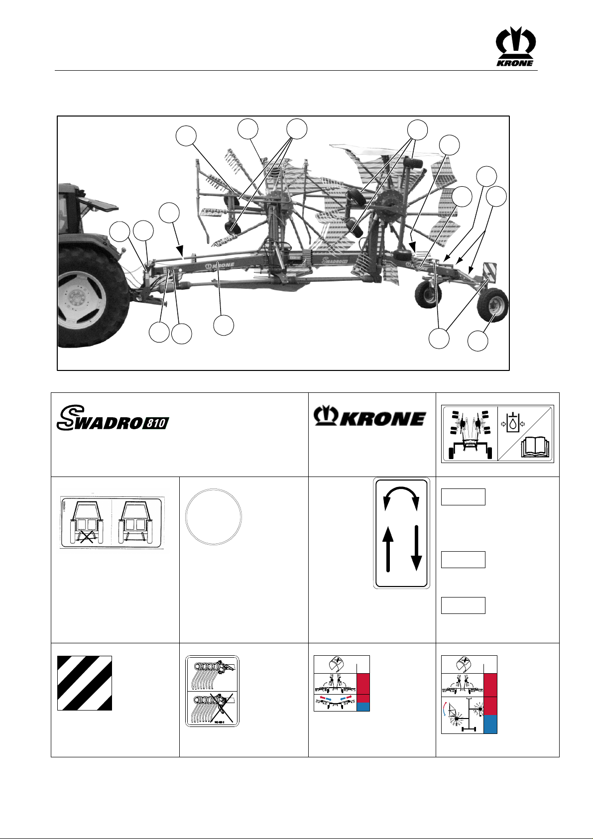
4.3 Position of the Adhesive Safety Stickers on the Machine
Pos:12.11/ BA/Sicherheit/Aufkleber/Schwader/Sich erheitsaufkleberSchw ader807/810/907 @1\mod_1 202220808716_78.doc@ 58071
GL
Fig. 2
6
3
6
2
6
1
7
5
4
6
SW810018
16
Page 17

Safety
1)
Before starting the machine,
read and observe the
operating instructions and
safety instructions.
Order No. 939 471-1 (1x)
3)
Before starting work, move
the hoop guards to the
protective position (fold
down).
Order No. 939 574 0 (2x)
939 574-0
5)
Do not stay in the swivel range of the outrigger
arms. Keep your distance!
2)
The PTO speeds must not exceed 540 rpm! The
operating pressure of the hydraulic system must
not exceed 200 bar!
939100-4
MAX. 540/min
MAX. 200 bar
Order No. 939 100-4 (1x)
4)
Danger in the area where rotors are turning -
Keep your distance!
939 472-2
Order No. 939 472-2 (2x)
6)
Never reach into the area where
there is danger of crushing as
long as parts could be moving.
Order No. 939 414-2 (1x)
7)
Keep the stipulated safe distance from power
transmission lines.
Order No. 942 293-0 (1x)
(Swadro 810, Swadro 809; Swadro 907)
Pos:12.12/ BA/-----Seitenumbruch------ @0\mod_119617 5311226_0.doc@ 4165
Order No. 942 196-1 (4x)
8)
17
Page 18
Safety
Pos:12.13/Ü berschriften/Überschriften 2/K-O/Lageder allgemeinen Hinweisaufklebera nderMasc hine@ 0\mod_1195635067920_78.doc @1039
4.4 Position of the General Information Labels on the Machine
Pos:12.14/ BA/Sicherheit/Aufkleber/Schwader/Hi nweisaufkleberSchwa der807/809/810/907 @75\mo d_1309756781199_78.doc @663805
Figure 3
1)
11
10
6
9
7a
7a
2
5
1
2
1
3
4
2
8
2)
7b
SW810019_4
3)
939 486-2
27 000 066 0 (2x) Swadro 807
27 008 496 0 (2x) Swadro 809
942 416 1 (2x) Swadro 810
27 001 557 0 (2x) Swadro 907
4)
939 420 1 (1x)
8)
924 569 0 (4x)
5)
40
939 145-1 (1x) 40 km
9)
942 480 0 (6x)
942 301 0 (2x) 775 mm
942 320 0 (2x) 600 mm
6)
942 339 0
942 339 0 (2x)
Mechanical in the Swadro
design.
10)
27 003 081 0 Swadro 810
270030 810
X
11
2
2
939 468 -2 (1x)
7a)
1,8 bar
939 183 1 1,8 bar
(16x Swadro 907 /
8x Swadro 807/809/810)
7b)
1,0 bar
Swadro 807/809/810
939 183 1 (2x) 1,0 bar
2,0 bar
Swadro 907
939 170-1 (2x) 2,0 bar
10)
X
11
2
2
27 003 080 0
Swadro 907
18
Page 19

11)
Safety
350-450/ min
942119-2
942 119 2 (1x)
Pos:12.15/ BA/Sicherheit/Kennzeichnung vonHinweis eninder Betriebsanleitung Einführungstext @0\ mod_1195637804826_78.doc @1098
4.5 Identifying Symbols in the Operating Instructions
The safety instructions contained in this manual which could result in personal injury if not
Pos:12.16/ BA/Sicherheit/Kennzeichnung derGefahren hinweise@ 28\mod_1250244370070_78.doc @274714
followed are identified by the general danger sign:
4.6 Identification of the hazard warnings
Danger!
DANGER! - Type and source of the hazard!
Effect: Danger to life or serious injuries.
• Measures for hazard prevention
Warning !
WARNING! - Type and source of the hazard!
Effect: Injuries, serious material damage.
• Measures for hazard prevention
Caution!
CAUTION! - Type and source of the hazard!
Pos:12.17/ BA/Sicherheit/Allgemeine Funktionshinweise @0\ mod_1196869714452_78.doc @15185
Pos:12.18/ BA/-----Seitenumbruch------ @0\mod_119617 5311226_0.doc@ 4165
Effect: Property damage
• Measures for risk prevention.
General function instructions are indicated as follows:
Note!
Note - Type and source of the note
Effect: Economic advantage of the machine
• Actions to be taken
Instructions which are attached to the machine need to be followed and kept fully legible.
19
Page 20

Safety
Pos:12.19.1/ BA/Sicherheit/Personalqualifikation und-Schulung @0\mod_119563 9383185_78.doc@ 1136
4.6.1 Personnel Qualification and Training Fehler! Textmarke nicht definiert.
The machine may be used, maintained and repaired only by persons who are familiar with it
and have been instructed about the dangers connected with it. The operator must define areas
of responsibility and monitoring of personnel. Should personnel lack the required knowledge,
they must receive the required training and instruction. The operator must ensure that the
contents of these operating instructions have been fully understood by personnel.
Repair work not described in these operating instructions should only be performed by
Pos:12.19.2/ BA/Sicherheit/Gefahren beiNichtbeachtung derSich erheitshinweise@ 0\mod_1195639434013_7 8.doc@1 155
4.6.2 Dangers in Case of Non-compliance with the Safety Instructions
Pos:12.19.3/ BA/Sicherheit/Sicherheitsbewußtes Arbeiten @0\mod_1195639792 576_78.doc@ 1174
4.6.3 Safety-conscious work practices
authorised service centres.
Failure to follow the safety instructions could result in personal injury and environmental
hazards as well as damage to the machine. If the safety instructions are not respected, this
could result in the forfeiture of any claims for damages.
Failure to follow the safety instructions could result, for example, in the following hazards:
• Endangering of persons due to not protected working areas.
• Breakdown of important machine functions
• Failure of prescribed methods for repair and maintenance
• Endangering of persons due to mechanical and chemical effects
• Damage to the environment due to leaking hydraulic oil
Pos:12.19.4/ BA/-----Seitenumbruch------ @0\mod_11961 75311226_0.doc@ 4165
Always observe the safety instructions set out in these operating instructions, all existing
accident prevention rules and any internal work, operating and safety rules issued by the
operator.
The safety and accident prevention regulations of the responsible professional associations are
binding.
The safety instructions provided by the vehicle manufacturer should also be observed.
Observe the applicable traffic laws when using public roads.
Be prepared for emergencies. Keep the fire extinguisher and first aid box within reach. Keep
emergency numbers for doctors and fire brigade close to the telephone.
20
Page 21

Pos:12.19.5/ BA/Sicherheit/Sicherheits- undUnfallverhüt ungs-VorschriftenSwa dro_Ladewagen_EasyCut @73\mod_130829858 9597_78.doc@ 655493
4.7 Safety Instructions and Accident Prevention Regulations
1 Please follow all generally applicable safety and accident prevention regulations in
addition to the safety instructions contained in these operating instructions!
2 The attached warning and safety signs provide important information for safe operation.
Pay attention to these for your own safety!
3 When using public roads, make sure to observe the applicable traffic regulations!
4 Make sure that you are familiar with all equipment and controls as well as with their
functions before you begin working with the machine. It is too late to learn this when you
are using the machine for work!
5 The user should wear close fitting clothes. Avoid wearing loose or baggy clothing.
6 Keep the machine clean to prevent the danger of fire!
7 Before starting or moving the machine, make certain that nobody is in the vicinity of the
machine! (Watch for children!) Make sure that you have a clear view!
8 Carrying passengers during operation and transport on the working implement is not
permitted.
9 Couple implements correctly! Attach and secure implements to specified devices only!
10 When attaching or detaching implements, place the supporting devices in the correct
positions!
11 Use extreme caution when attaching or detaching implements onto or from the tractor!
12 Always attach ballast weights properly to the fixing points provided!
13 Observe permitted axle loads, gross weight and transport dimensions!
14 Check and attach transport equipment, such as lighting, warning devices and protective
equipment!
15 Actuating mechanisms (cables, chains, linkages etc.) for remote controlled devices must
be positioned in such a way that no movements are unintentionally triggered in any
transport or working positions.
16 Ensure that implements are in the prescribed condition for on-road travel and lock them in
place in accordance with the manufacturer's instructions!
17 Never leave the driver's seat when the vehicle is moving!
18 Always drive at the correct speed for the prevailing driving conditions! Avoid sudden
changes in direction when travelling uphill or downhill or across a gradient!
19 Hitched implements and ballast weights affect the driving, steering and braking response
of the machine. Make sure that you are able to brake and steer the machine as required!
20 Take into account the extension radius and/or inertia of an implement when turning
corners!
21 Start up implements only when all safety devices have been attached and set in the
required position!
22 Keep safety equipment in good condition. Replace missing or damaged parts.
23 Keep clear of the working range of the machine at all times!
24 Do not stand within the turning and swivel range of the implement!
25 Never operate the hydraulic folding frames if anyone is inside the swivel range!
Safety
21
Page 22

Safety
26 Parts operated by external power (e.g. hydraulically) can cause crushing and shearing
injuries!
27 Before leaving the tractor, lower the implement onto the ground, apply the parking brake,
Pos:12.19.6/ BA/Sicherheit/Angehängte Geräte/Geräte angehängt@ 0\mod_1199699679381_78.doc @33245
4.8 Hitched Implements
Pos:12.19.7/ BA/-----Seitenumbruch------ @0\mod_11961 75311226_0.doc@ 4165
switch off the engine and remove the ignition key!
1 Secure implements against rolling.
2 Observe the maximum supported load on the trailer coupling, swing drawbar or hitch!
3 If a drawbar coupling is used, make certain that there is enough play at the coupling
point.
22
Page 23

Pos:12.19.8/ BA/Sicherheit/Zapfwellenbetrieb Traktor@ 0\mod_119969989935 0_78.doc@ 33264
4.9 PTO operation
1 Use only PTO shafts specified by the manufacturer!
2 The guard tube and guard cone of the PTO shaft and the PTO guard must be attached
and in good working condition (on the implement side, too)!
3 Make sure that the required tube covers are in place for PTO shafts in transport and
working position!
4 Before installing or detaching PTO shafts, disengage the PTO, switch off the engine and
remove the ignition key!
5 When using PTO shafts with an overload safety or free-running coupling which are not
shielded by the guard on the tractor, mount the overload safety or free-running coupling
on the implement side!
6 Always make sure that the PTO shaft is properly installed and secured!
7 Attach chains to prevent the PTO shaft guard from rotating with the shaft!
8 Before switching on the PTO, make sure that the selected PTO speed of the tractor
matches the permissible implement speed!
9 Before switching on the PTO shaft make sure that no person is in the danger zone of the
device!
10 Never switch on the PTO if the engine is switched off!
11 No one should be in the vicinity of the rotating PTO or PTO shaft when the PTO is in use.
12 Always switch off the PTO shaft when the angle is too large or the PTO shaft is not
required!
13 Caution! After disengaging the PTO danger due to the flywheel running on! Keep away
from the implement during this time. The machine may be worked on only if it is
completely at standstill and if the flywheel is secured by the parking brake.
14 Cleaning, lubricating or adjusting PTO driven implements or the PTO shaft only with PTO
disengaged, engine switched off and ignition key withdrawn! Secure the fly-wheel with the
parking brake.
15 Place the disconnected PTO shaft onto the support provided!
16 After detaching the PTO shaft, attach the protective cover to the PTO end!
17 If damage occurs, correct this immediately before using the implement!
Pos:12.19.9/ BA/Sicherheit/Zapfwellenbetrieb Zusatz@ 2\mod_1203524761314_ 78.doc@ 66513
Safety
Pos:12.19.10 /BA/-----Seitenumbruch------ @0\mod_1196 175311226_0.doc@ 4165
Note
The instructions of the manufacturer must be observed with regard to the PTO shaft. (separate
operating instructions)
23
Page 24

Safety
Pos:12.19.11 /BA/Sicherheit/Hydraulikanlage @2\mod_1 203503691986_78.doc@ 66225
4.10 Hydraulic system
1 The hydraulic system is pressurised!
2 When connecting hydraulic cylinders and motors, make sure the hydraulic hoses are
connected as specified!
3 When connecting the hydraulic hoses to the tractor hydraulics, make sure that the
hydraulics of both the tractor and the implement have been depressurized!
4 In the case of hydraulic connections between tractor and machine, the coupling sleeves
and plugs should be marked to ensure a proper connection! Bei Vertauschen der
Anschlüsse umgekehrte Funktion (z.B. Heben/Senken) - Unfallgefahr!
5 When searching for leaks, use suitable aids to avoid the risk of injury!
6 Liquids escaping under high pressure (hydraulic oil) can penetrate the skin and cause
serious injury! Seek medical help immediately should injuries occur! Danger of infection!
7 Before working on the hydraulic system, depressurise the system and switch off the
Pos:12.19.12 /Überschriften/Überschriften 2/P-T/Reifen@ 0\mod_119735799566 7_78.doc@ 18075
4.11 Tyres
Pos:12.19.13 /BA/Sicherheit/Reifen @0\mod_119564643 5716_78.doc@ 1346
Pos:12.19.14 /BA/-----Seitenumbruch------ @0\mod_1196 175311226_0.doc@ 4165
engine!
1 When working on the tyres, make sure that the implement is safely lowered and secured
against rolling (wheel chocks).
2 Installing wheels and tyres requires adequate knowledge and suitable tools!
3 Repair work on the tyres and wheels should be done by specially trained personnel using
appropriate installation tools only!
4 Check tyre pressure regularly! Inflate the tyres to the recommended pressures!
5 Check the wheel nuts periodically! Missing wheel nuts can result in a wheel falling off and
the machine tipping over.
24
Page 25

Pos:12.19.15 /BA/Sicherheit/Wartung/Wartung Swadro@ 2\mod_1203504022 126_78.doc@ 66245
4.12 Maintenance
1 Always make certain that the drive and the engine are switched off before doing any
repairs, maintenance or cleaning! - Remove the ignition key!
2 Regularly check that nuts and bolts are properly seated and tighten if necessary!
3 When performing maintenance work with the machine raised, always secure it with
suitable supporting elements!
4 Oils, greases and filters must be disposed of correctly!
5 Always disconnect the power supply before working on the electrical system!
6 If protective devices and guards are subject to wear, check them regularly and replace
them in good time!
7 When performing electrical welding work on the vehicle and mounted devices, turn power
supply off at main battery switch or disconnect generator cable and battery!
8 Replacement parts must at least comply with the technical requirements set by the
Pos:12.19.16 /BA/-----Seitenumbruch------ @0\mod_1196 175311226_0.doc@ 4165
manufacturer of the implements! This is guaranteed by original KRONE spare parts!
Safety
25
Page 26

Safety
Pos:12.19.17 /BA/Sicherheit/Arbeiteni mBereich vonHochspan nungsleitungen@ 11\mod_1223357468516_78 .doc@ 145505
4.13 Working in the vicinity of power transmission lines
1 Always take great care when working under or in the vicinity of power transmission lines.
2 Ensure that when in operation or being transported, the machine cannot exceed a total
height of approx. 4m.
3 If there is any need to travel under overhead lines, the machine operator must request
information on the rated voltage and the minimum height of the overhead lines from the
overhead line operator.
4 Always keep the safety distances according to the table.
Rated voltage
kV
Safe distance from overhead lines
m
To 1 1
Above 1 to 110 2
Above 101 to 220 3
Above 220 to 380 4
Pos:12.19.18 /BA/Sicherheit/Eigenmächtiger Umbauund Ersatzteilherstellung @1\mo d_1201937705539_78.doc @55745
4.14 Unauthorised Conversion/Modification and Spare Parts Production
Conversions or modifications of the machine are permitted only with prior consultation with the
manufacturer. Original spare parts and accessories authorised by the manufacturer help to
Pos:12.19.19 /BA/Sicherheit/Unzulässige Betriebsweisen @11\mod_1223357 699923_78.doc@ 145527
ensure safety. Use of other parts may void liability for resulting damage.
4.15 Inadmissible Modes of Operation
The operating safety of the delivered machine is guaranteed only when it is used as intended in
compliance with the introductory section "Intended use" of the operating instructions. The limit
Pos:12.19.20 /BA/Sicherheit/Sicherheitshinweise ander Maschine@ 1\mod_120193786 1961_78.doc@ 55783
values listed in the data charts should not be exceeded under any circumstances.
4.16 Safety Instructions on the Machine
The safety instructions on the machine warn of residual risks associated with the machine. They
consist of warning pictograms and a work safety symbol. All safety instructions must be
followed. Always keep the safety instructions clean and in clearly legible condition! If any safety
instructions are damaged or missing, request them from your dealer and then put them in the
places provided for them. Where these safety instructions are and what they mean will be
described in the following chapters.
Pos:13/BA/-- ---Seitenumbruch------ @0\mod_119617531 1226_0.doc@ 4165
26
Page 27

Pos:14.1/Üb erschriften/Überschriften 1/A-E/Erstinbetriebnahme @0\mod_11963 14201498_78.doc@ 5855
5 Commissioning
Pos:14.2/B A/Sicherheit/Gefahrenhinweise/Fehlerh afterZusammenbau @1\m od_1202224212591_78.doc@ 58171
Danger! - Incorrect assembly
Effect: Danger to life, serious injuries or serious damage to the machine.
• Only authorised service centres may assemble the machine.
• The machine must be assembled with special care.
• Always heed the applicable accident prevention regulations.
• Use only safe and sufficiently dimensioned lifting equipment and load-securing
equipment.
• The machine may be taken into operation only after all the safety devices have been
installed.
• If unauthorised modifications are made to the machine, the manufacturer is released
from liability for any resulting damage.
Pos:14.3/B A/Sicherheit/Gefahrenhinweise/Einstell arbeitengezogene Maschinen@ 0\mod_1199717 011038_78.doc@ 33980
Danger! - Unexpected movements of the machine
Effect: Danger to life or serious injuries.
• Setting tasks must only be performed when the drive is switched off and the engine is at
a standstill!
• Switching off the engine
• Remove the ignition key.
• Secure the machine against the possibility of rolling back.
Pos:14.4/Üb erschriften/Überschriften 2/A-E/Erstmontage @1\mod_12022262 61982_78.doc@ 58270
5.1 First installation
Pos:14.5/B A/Erstinbetriebnahme/Erstmontage @1\mod _1202224111998_78.doc @58190
Pos:14.6/B A/-----Seitenumbruch------ @0\mod_1196175 311226_0.doc@ 4165
The document "Assembly Instructions" describes how to install the device for the first time.
Commissioning
27
Page 28

Commissioning
Pos:14.7.1 /Überschriften/Überschriften 2/U-Z/Vorbereitungen amTraktor @2\mod_120 2363643678_78.doc@ 58694
5.2 Preparations on tractor
Pos:14.7.2 /Überschriften/Überschriften 3/U-Z/Unterlenker einstellen@ 6\mod_1214454896135_78.doc @941 86
5.2.1 Adjusting the lower suspension arms
Pos:14.7.3 /BA/Erstinbetriebnahme/Schwader/S wadro807_810_907/Bil d_AushubvorrichtungTr aktor@2 \mod_1202364384960_78.doc @58789
KS-0-030
Pos:14.7.4 /BA/Erstinbetriebnahme/Schwader/S wadro807_810_907/Vor bereitungan Traktor_TextKAT Iund II@ 2\mod_1202363818163_78.d oc@ 58732
Fig. 4
The machine is equipped with Cat. I and II trunnions for three-point hydraulics.
Pos:14.7.5 /BA/Erstinbetriebnahme/Schwader/S wadro807_810_907/Hinw eisUnterlenker @2\mod_1 202364126303_78.doc@ 58751
Note
The tractor lower suspension arms must always be installed so that the lifting points of the
lower suspension arms are all at the same distance from the ground. In order to prevent
swivelling of the machine during transport or operation, the lower suspension arms must be
secured by limiting chains or bars.
Pos:14.8/B A/-----Seitenumbruch------ @0\mod_1196175 311226_0.doc@ 4165
28
Page 29

Pos:14.9.1 /Überschriften/Überschriften 2/F-J/Gelenkwelle @0\mod_11997818 79794_78.doc@ 34542
5.3 PTO shaft
Pos:14.9.2 /Überschriften/Überschriften 3/K-O/Längenanpassung @1\mod_120 1687632810_78.doc@ 53589
5.3.1 Length adjustment
Pos:14.9.3 /BA/Erstinbetriebnahme/Gelenkwelle/Sc hwader/Längenanpassung BildSchwader @2\mod _1202364902991_78.doc@ 58848
3
1
Commissioning
2
SW9070007
Pos:14.9.4 /BA/Erstinbetriebnahme/Gelenkwelle/Sc hwader/Längenanpassung_mit WeitwinkelTe xt_Schwader@ 2\mod_1202365111491_78.doc @5 8868
Fig. 5
The PTO shaft (1) length must be adjusted.
• Disassemble the PTO shaft.
• Install each half (1) and (2) on the tractor and machine side respectively.
(The wide-angle coupling must be installed onto the machine. Observe the marking on
the PTO shaft.)
• Position rotary rake in the shortest PTO shaft position setting. (Completely the three-
• For additional operating instructions refer to the operating instructions of the PTO shaft
Note
Check the swivel range and clearance of the PTO shaft! Damage can be caused if the tractor
or the machine touch the PTO shaft. (e.g. hitching device, hitching frame)
Pos:14.10/ BA/-----Seitenumbruch------ @0\mod_119617 5311226_0.doc@ 4165
point frame inwards.)
manufacturer.
29
Page 30

Commissioning
Pos:14.11/Ü berschriften/Überschriften 2/F-J/Höheder Traktorunterlenker @35\mod_12 57862892625_78.doc@ 332062
5.4 Height of tractor lower suspension arms
Pos:14.12/ BA/Erstinbetriebnahme/Schwader/Sw adro807_810_907/Höh ederTr aktorunterlenker@ 2\mod_1202734685720_ 78.doc@ 60755
SW9070025
Figure 6
Perform basic setting on a level surface.
The tractor lower suspension arms must be set at a height which ensures that the steerable
pinions are at a height of H approx. 63 cm from the ground. Fix the lower suspension arms at
this height (see Chapter on special equipment "Chain for height restriction of lower suspension
Pos:15/BA/-- ---Seitenumbruch------ @0\mod_119617531 1226_0.doc@ 4165
arms").
30
Page 31

Pos:16.1/Üb erschriften/Überschriften 1/F-J/Inbetriebnahme @0\mod_1196327 075811_78.doc@ 6375
6 Start-up
Pos:16.2/B A/Sicherheit/Gefahrenhinweise/Schwa der/An-/Abau derMaschine gezogene Schwader@ 2\mod_1202363265522_78.doc @58675
Danger! - Assembling / dismantling the machine
Effect: Danger to life or serious injuries.
• No persons may remain between the tractor and the machine.
• Nobody should be within the swivel range of the rotary arms or of the working range of
the rotary rake!
• Only perform jobs under or on the machine when it is raised if it is securely supported.
• Setting tasks must only be performed when the drive is switched off and the engine is at
a standstill!
• Switching off the engine
• Remove the ignition key.
• Secure the machine against the possibility of rolling back.
Pos:16.3/Üb erschriften/Überschriften 2/A-E/Anbauan denTrakt or@0\m od_1199717845194_78.doc @34039
6.1 Mounting onto the Tractor
Pos:16.4/B A/Sicherheit/Gefahrenhinweise/Lad ewagen/Stütz-und Anhängelastend esSchleppers nichtbeachtet @0\m od_1199720048038_78.doc @34118
Danger! - Support and hitching loads of tractor not observed!
Effect: Danger to life, injuries or damage to the machine.
• Observe the maximum permissible support and hitching loads for the tractor!
• Hitch and secure the machine to the tractor hitch in accordance with specifications.
Pos:16.5/B A/Inbetriebnahme/Schwader/Hinweis Maschine befindetsich inTransportstellu ng@2 \mod_1202388231928_78.doc @59050
Start-up
Note
The description below assumes that the
swather is in transport position, following final assembly.
Pos:16.6/B A/Inbetriebnahme/Schwader/Anbau anden Traktor/Anbau anden Traktor angehängteSch wader@2\ mod_1202389539585_78.doc @59089
Figure 7:
• Hitch double swather with steerable pinions onto tractor.
• Place the machine onto the parking supports.
Pos:16.7/B A/-----Seitenumbruch------ @0\mod_1196175 311226_0.doc@ 4165
SW9070002
31
Page 32

Start-up
Pos:16.8/Üb erschriften/Überschriften 2/F-J/Hydraulik@ 0\mod_119977603495 0_78.doc@ 34205
6.2 Hydraulics
Pos:16.9/Üb erschriften/Überschriften 3/P-T/SpezielleSic herheitshinweise@ 0\mod_1197301069931_7 8.doc@1 7662
6.2.1 Special Safety Instructions
Pos:16.10/ BA/Sicherheit/Hydraulik/Gefahr Anschlussd erHydraulikleitungen @0\mo d_1199776548685_78.doc @34225
Warning ! - Connection of the hydraulic line
Effect: severe injuries due to penetration of hydraulic oil under the skin.
• When connecting the hydraulic hoses to the hydraulic system of the tractor, the system
must be relieved of the pressure on either side.
• Due to the risk of injury when searching for leaks, always use suitable tools and wear
protective goggles.
• Seek medical help immediately should injuries occur! Danger of infection.
• Depressurise prior to uncoupling the hydraulic hoses and working on the hydraulic
system!
• Check the hydraulic hose lines at regular intervals and replace them if damaged or worn!
The replacement hoses must fulfil the technical requirements set by the equipment
manufacturer.
Pos:16.11/ BA/Sicherheit/Hydraulik/Verschmutzu ngderH ydraulikanlage@ 2\mod_1202393336803_7 8.doc@5 9155
Caution! - Soiling of the hydraulic system
Effect: Damages to the machine
• When connecting the quick couplings, ensure that these are clean and dry.
• Note chafing areas or points of contact.
Pos:16.12/ BA/-----Seitenumbruch------ @0\mod_119617 5311226_0.doc@ 4165
32
Page 33

Pos:16.13/Ü berschriften/Überschriften 3/A-E/Anschlussd erHydraulikleitunge n@0\mo d_1199777037794_78.doc @34244
6.2.2 Connecting the hydraulic lines
Pos:16.14/ BA/Inbetriebnahme/Schwader/Hydr aulikanschluss/Hydraulikanschluss BildSchwadr o807_809_810_907 @75\mo d_1309764074531_78.doc @664029
2
1
Start-up
SW9070003
Pos:16.15/ BA/Inbetriebnahme/Schwader/Hinw eisHydraulikaufkleber beachten@ 9\mod_12199975317 85_78.doc@ 124879
Figure 8
Note
Connect the hydraulic lines correctly
• The hydraulic hoses are identified by coloured hose clips.
• When connecting the hydraulic lines, observe the sticker for the tractor hydraulics (see
Pos:16.16/ BA/Inbetriebnahme/Schwader/Hydr aulikanschluss/Amtraktor benötigteS teuergeräte@ 75\mod_1309762615205_7 8.doc@6 64001
Pos:16.17/ Abkürzungen/Abkürz ungensprachneutral/Sc hwader/Swadro807 /Swadro 809@ 76\mod_1309764684788_ 0.doc@ 664085
Pos:16.18/ BA/Inbetriebnahme/Schwader/Hydr aulikanschluss/Hydraulikanschluss Schwadro80 7_809Text @75\mod_1309762 054242_78.doc@ 663973
The following control units are required on the tractor to operate the machine:
Swadro 807 / Swadro 809
The machine requires a single-action control unit on the tractor.
Connect the hydraulic hose as follows:
to the single-action control unit:
• (2) red= - lift/lower rotor arms
Pos:16.19/ Abkürzungen/Abkürz ungensprachneutral/Sc hwader/Swadro810 @2\mod_ 1202740024298_0.doc@ 60813
Pos:16.20/ BA/Inbetriebnahme/Schwader/Hydr aulikanschluss/Hydraulikanschluss Schwadro81 0Text@ 75\mod_13097616346 63_78.doc@ 663945
Swadro 810
The machine requires a single-action and a double-action control unit on the tractor.
Connect the hydraulic hoses as follows:
to the single-action control unit:
• (1) red= - lift/lower rotor arms
to the double-action control unit:
• (2) red = increase working width setting
• (2) blue= - reduce working width setting
Pos:16.21/ Abkürzungen/Abkürz ungensprachneutral/Sc hwader/Swadro907 @1\mod_ 1202226168013_0.doc@ 58250
Pos:16.22/ BA/Inbetriebnahme/Schwader/Hydr aulikanschluss/Hydraulikanschluss Schwadro90 7Text@ 75\mod_13097609676 69_78.doc@ 663917
Swadro 907
The machine requires a single-action and a double-action control unit on the tractor.
Connect the hydraulic hoses as follows:
to the single-action control unit:
• (1) red= - lift/lower rotor arms
to the double-action control unit:
• (2) red= - adjust swath cloth forwards
• (2) blue= - adjust swath cloth backwards
Pos:16.23/ BA/-----Seitenumbruch------ @0\mod_119617 5311226_0.doc@ 4165
the "Safety" chapter: "Position of the general information labels on the machine").
33
Page 34

Start-up
Pos:16.24/Ü berschriften/Überschriften 2/A-E/AnschlussB eleuchtung@ 33\mod_1254385308979_78. doc@3 19105
6.3 Lighting connection
Pos:16.25/ BA/Inbetriebnahme/Schwader/Ansc hlussBeleuchtung/Ansc hlussBeleuchtung Swadro807 810S wadro907 @2\mod_1202391626 522_78.doc@ 59135
3
Fig. 9
The lighting system is connected via the 7-pin connection cable (1).
To do this:
• Insert the 7-pin connection cable plug (1) into the appropriate socket (2) of the tractor.
• Insert the 7-pin connection cable plug (1) into the appropriate socket (3) of the machine.
Pos:16.26/ BA/Inbetriebnahme/Schwader/Hinw eisSauberkeit derStecker undSteckdose n@2\ mod_1202399563131_78.doc @59273
Pos:16.27/ BA/-----Seitenumbruch------ @0\mod_119617 5311226_0.doc@ 4165
• Position the cable so that it will not come in contact with the wheels.
Note
Before inserting the plugs, make certain the plugs and sockets are clean and dry. Dirt and
moisture may result in short circuits!
2
1
1
SW9070004
34
Page 35

Pos:16.28/Ü berschriften/Überschriften 2/A-E/Anschlußd erelektrischen Bedienung@ 2\mod_1202396974288_ 78.doc@ 59195
6.4 Connecting the electrical controls
Pos:16.29/ BA/Inbetriebnahme/Schwader/Option alfürSw adro810_907 @2\mod_12023 97282038_78.doc@ 59214
Pos:16.30/ BA/Inbetriebnahme/Schwader/Ansc hlusselektrische Bedienung/Anschluss elektrische Bedienung SW807_810_907 @2\mod_1202 396707631_78.doc@ 59175
(Optional for Swadro 810; Swadro 907)
Start-up
Pos:16.31/ BA/Inbetriebnahme/Schwader/Hinw eisSauberkeit derStecker undSteckdose n@2\ mod_1202399563131_78.doc @59273
Pos:16.32/ BA/-----Seitenumbruch------ @0\mod_119617 5311226_0.doc@ 4165
1
2
1
3
SW9070005
Fig. 10
The connection of the electrical controls is made with the power supply plug (1)
Note
If necessary, the continuous power socket and support for the control unit must be previously
installed on the tractor.
To do this:
• Insert the plug for the electrical power supply cable (1) into the appropriate socket (2) of
the tractor.
• Insert the plug for the electrical power supply cable (1) into the appropriate socket (3) of
the machine.
• Position the cable so that it will not come in contact with the wheels.
Note
Before inserting the plugs, make certain the plugs and sockets are clean and dry. Dirt and
moisture may result in short circuits!
35
Page 36

Start-up
Pos:16.33/Ü berschriften/Überschriften 2/F-J/Gelenkwelle montieren@ 2\mod_1202398342788_78.doc @592 53
6.5 Install the PTO shaft
Pos:16.34/ BA/Sicherheit/Gelenkwelle/Sich drehendeGel enkwelle_2@ 0\mod_1199781692950_78.doc @3452 3
Danger! - Rotating PTO shaft
Effect: Danger to life or serious injuries
• Install or detach the PTO shaft only with the engine switched off and the ignition key
removed.
• Secure the tractor against rolling.
• Make sure that the PTO shaft is coupled properly (the lock of the PTO shaft must have
snapped in).
• Make sure that the protective devices are attached properly.
• Never use a PTO shaft, the protective devices of which have not been attached.
• Replace damaged protective devices immediately
• Attach the safety chain of the PTO shaft so that the guard tube does not rotate
simultaneously with the PTO shaft.
Pos:16.35/ BA/Inbetriebnahme/Schwader/Anba uGelenkwelle/Anbau Gelenkwellea ngehängteSchwa derBild@ 2\mod_12023980779 60_78.doc@ 59233
3
Pos:16.36/ BA/Inbetriebnahme/Schwader/Anba uGelenkwelle/Anbau Gelenkwellea ngehängteSchwa derText@ 37\mod_12634637723 93_78.doc@ 339645
Figure 11
• Switch off the engine and remove the ignition key.
• Install the PTO shaft (1) on the machine side (wide angle on machine side).
• Rotate the PTO shaft support (2) upwards.
• Then slide PTO shaft onto the PTO of the tractor. In doing this, ensure that the sliding pin
Pos:16.37/ BA/Inbetriebnahme/Schwader/Maschin eanheben wennBedienseil @2\mod _1202826885966_78.doc@ 61845
• Secure the PTO shaft guard against turning with the retaining chain (3).
Lifting the Machine
• The actuator rope (6) must be routed in such a way that no movements are
• Lift the machine slightly.
• Rotate the parking support (4) back 90°. Lock it in that position with the bracket (5) and
Pos:17/BA/-- ---Seitenumbruch------ @0\mod_119617531 1226_0.doc@ 4165
6
3
2
1
5
4
SW9070008
is securely engaged.
unintentionally triggered in any transport or working positions. The actuator rope must not
come into contact with the tractor tyres.
secure with spring cotter pin.
36
Page 37

Pos:18.1/Üb erschriften/Überschriften 1/F-J/Fahrenund Transport@ 0\mod_119633004 9217_78.doc@ 6553
7 Driving and Transport
Pos:18.2/B A/Sicherheit/Fahrenu ndTransport/Mitfahren Straßenfahrt/Gefahr Straßenfahrt,M itfahrengezogen eSwadros@ 2\mod_12024563155 26_78.doc@ 59426
Danger! - Road travel, carrying passengers, driving conduct
Effect: Danger to life, injuries or damage to the machine.
• The machine must be fully and correctly hitched.
• The side hoop guards of the machine must be attached.
• The collapsible tine arms must be rotated.
• The machine must be in transport position.
• The tine guards must be installed on tines.
• The control unit must be turned off.
• Do not exceed the maximum permissible speed (see type plate).
• Carrying passengers on the machine is not permitted.
• When driving on public roads, the provisions of the Road Traffic Licensing Regulations
must be adhered to (lighting, identification).
• Before starting, ensure that you have perfect visibility on and around the tractor as well
as the machine.
Pos:18.3/B A/Sicherheit/Fahrenu ndTransport/Mitfahren Straßenfahrt/Gefahr Straßenfahrt,M itfahrenSwadro zusatzSW 807/810/907 @2\mod_12029 20546961_78.doc@ 63113
Danger! - Road travel, passengers and handling
Effect: Danger to life, injuries or damage to the machine.
• The width setting of the rotor arms must always be completely retracted (Swadro 810)
• Check to make certain the locks have engaged correctly.
• Before each transport trip, charge the outrigger arm hydraulic cylinders with pressure and
then set the tractor hydraulics to "Neutral" so the outrigger arm transport interlocks are
not under any load.
Driving and Transport
Pos:18.4/B A/-----Seitenumbruch------ @0\mod_1196175 311226_0.doc@ 4165
37
Page 38

Driving and Transport
Pos:18.5/B A/Fahrenund Transport/Schwader/Vorbereitu ngfürd enTransport Swadro807_809_8 10_907@ 76\mod_1309765675876_78.doc @664143
Swadro 907
1
1
2
1
SW9070015
Swadro 807, Swadro 809, Swadro 810
1
1
SW810004_1
Fig. 12
• Switch off the control unit (Swadro 810; Swadro 907 optional)
• Fold over the folding tine arms (right and left side of machine) (see section on Operation
"Swivelling the Tine Arms into Transport Position").
• Fix the rotor in place (see section on Operation "Swivelling the Tine Arms into Transport
Position").
• Move the swath cloth to transport position (see section on Operation "Pushing the Swath
Cloth into Transport Position")
• Fold up the bar. (see section on Operation "Moving the Outer Guards into Transport
Position").
• Lift the rotor until the front and rear locks engage in the retaining bolt (see section on
Operation "Lifting the Rotor Arms to Transport Position").
Pos:19/BA/-- ---Seitenumbruch------ @0\mod_119617531 1226_0.doc@ 4165
38
Note
Make certain the transport locks engage correctly and the actuator rope is not tight.
Swadro 907
The locks (1) on the Swadro 907 have engaged correctly when the white spotlights (2) can be
seen from the tractor with the outrigger arms in vertical position (front rotor and rear rotor).
Swadro 807, Swadro 809, Swadro810
Perform a visual inspection to ensure the locks (1) have engaged correctly.
• Move the hydraulic control unit to neutral position.
• Insert the tine guard onto the tines, which are in transport position below 2 m. (see
section on Operation "Protecting the Tine Tips")
• Check the lighting system.
Page 39

Pos:20.1/Üb erschriften/Überschriften 1/A-E/Bedienung@ 0\mod_119978950540 3_78.doc@ 34825
8 Operation
Pos:20.2/B A/Bedienung/Schwad er/Maschineist fürVorwärtsf ahrtkonzipiert. @66\mod_13021 75087311_78.doc@ 615098
WARNING! – Do not drive in reverse when using the machine for work.
Effect: Damage to the machine.
The machine is designed to travel forwards. Never reverse while the machine is in operation
and in working position. Lift the rotor first.
Pos:20.3.1 /Überschriften/Überschriften 2/U-Z/Überlastsicherung @2\mod_12 02465560433_78.doc@ 59567
8.1 Overload protection
Pos:20.3.2 /BA/Bedienung/Sch wader/Überlastsicherung/Überlastsicheru ngBild Swadro807_809_810_ 907@7 6\mod_1309768647507_78.doc @664230
Operation
Swadro 907
1
SW9070031
Pos:20.3.3 /BA/Bedienung/Sch wader/Überlastsicherung/Überlastsicheru ngTextS W807_810_907_10 00@2\m od_1202465701839_78.doc @59605
Fig. 13
Star ratchet couplings protect the machine against overloading. These star ratchets (1) are
located on the side output shafts of the transfer gearbox behind the rotor arms. They emit a
vibrating sound when the machine is overloaded. They transfer the related torque by pulsations.
In order to avoid premature wear of the overload protection, turn the PTO shaft of immediately
when the star ratchets respond to the overload.
Pos:20.3.4 /BA/Bedienung/Sch wader/Überlastsicherung/Hinweis Überlastsicherung nichtverändern @2\mod_1 202465626026_78.doc@ 59586
Pos:20.4/B A/-----Seitenumbruch------ @0\mod_1196175 311226_0.doc@ 4165
Note
The overload protection must not be changed. The guarantee becomes invalid if an overload
protection is used other the protection provided!
39
Page 40

Operation
Pos:20.5/Üb erschriften/Überschriften 2/U-Z/VonTransport inAr beitsstellung@ 2\mod_1202466185276_78.doc @596 62
8.2 From transport into working position
Pos:20.6/B A/Sicherheit/Gefahrenhinweise/Schwa der/GefahrMaschine absenken@ 5\mod_121369480 5078_78.doc@ 88774
Danger! – Lowering the machine into working position
Danger to life, injuries or damage to the machine.
• Lower the machine only when you are absolutely sure that neither persons, animals nor
objects are in the swivel range of the machine.
• Switch the PTO on only when the machine is in working position, the collapsible tine
arms are swivelled into the working position and the hoop guards are turned downwards.
Pos:20.7/B A/Bedienung/Schwad er/Zinken/Zi nkenarme/Zinkenschutze entfernenSW 807/810/907 @2\mod_1202467 038839_78.doc@ 59738
8.3 Removing the tine protections from the tine tips
1
2
1
Figure 14
• Remove the tine protections (1).
• Insert the tine protections into the support (2) (right and left side of the machine) and and
secure with the linch pin.
Pos:20.8/Üb erschriften/Überschriften 2/K-O/Kreiselarmei ndieAr beitsstellungabsenke n@ 37\mod_1263474967690_7 8.doc@ 339871
8.4 Lowering the rotor arms into working position
Pos:20.9/B A/Bedienung/Schwad er/Kreiselarmesenke n/heben/Kreiselarmese nken-mec hanischSW 807_810_907@ 2\mod_1202466847230 _78.doc@ 59719
• Activate the single-action control valve on the tractor and apply pressure to the hydraulic
cylinder. This relieves the load on the lock.
• Pull on the actuator rope to disengage the lock. Leave the rope under tension.
• Slowly lower the external rotor with the control valve until the wheels are resting on the
ground.
• Release the pull rope.
Note
Leave the control valve in "Lower" position when using the machine for work
Pos:20.10/ BA/-----Seitenumbruch------ @0\mod_119617 5311226_0.doc@ 4165
SW9070021
40
Page 41

Pos:20.11.1/ BA/Bedienung/Sc hwader/Schwadtuch/Schwadformer/Einst ellendes hinterenSchwadtuches Swadro 807_809_810@ 76\mod_1309769433478_7 8.doc@ 664286
8.5 Adjusting the Rear Swath Cloth
(Swadro 807/ 809/ 810)
Operation
Pos:20.11.2/ BA/Bedienung/Sc hwader/Schwadtuch/Schwadformer/Sch wadtuchallgemein @2\mod_12 02830085935_78.doc@ 61884
Fig. 15
Note
The swath cloth must be set while the rotor arms are lowered.
The tractor engine must be turned off and the ignition key must be removed.
The distance from the swath former to the rotor can be adjusted for narrow or wide swathing or
to continuously adapt to the amount of forage. The distance from the swath former to the rotor
must be adjusted for the amount of forage.
High amount of forage = long distance
Small amount of forage = short distance
Pos:20.11.3/ BA/Bedienung/Sc hwader/Schwadtuch/Schwadformer/Stec kbolzenfür dieArbeitsstelllung umstecken@ 78\mod_131366 7230110_78.doc@ 693473
• For the working position, the socket pin (3) must be reconnected from pos. I to pos. II.
1
2
and secured.
1
3
Pos.I
Pos.II
SW810023_2
Note
The socket pin (3) prevents in pos. I that the swath former comes in contact with the tines of the
rotor.
Pos:20.11.4/ BA/Bedienung/Sc hwader/Schwadtuch/Schwadformer/Sch wadtucheinstellen Swadro807 _810@7 8\mod_1313670766215_78.doc @693500
• To do this, loosen the cone grip and set screw (1), move the swath former (2) to the
Pos:20.11.5/ BA/-----Seitenumbruch------ @0\mod_11961 75311226_0.doc@ 4165
correct position and then tighten the cone grip and set screw (1) again.
41
Page 42

Operation
Pos:20.11.6/ BA/Bedienung/Sc hwader/Schwadtuch/Schwadformer/Sch wadformerLängsricht ungHöhenverstellung Swadro80 7/810@ 16\mod_1234454540727_78.doc @182318
Pos.I
2
6
3
Fig. 16
Adjusting the swath former lengthwise
Adjusting the swath former lengthwise. This adjustment is required for example if forage falls out
at the front of the swath former. To make the adjustment, loosen the screws (3), move the swath
former to the desired position and tighten the screws (3) again.
Pos:20.11.7/ BA/Bedienung/Sc hwader/Schwadtuch/Schwadformer/Hö henverstellungdes Schwadformers SW46T/SW907 @7\mod_12 15682459926_78.doc@ 105175
8.5.1 Height adjustment of the swath former
The adjustment is required if forage falls under the swath former, for example, and is not
evened out by the working depth adjustment.
To do this:
• Unscrew the linch pins (2).
• Remove the swath former from its support.
• Reinstall the sleeves (6).
Pos:20.11.8/ BA/Bedienung/Sc hwader/Schwadtuch/Schwadformer/Einst ellendes vorderenSchwadtuch es@ 2\mod_1202708893064_78.doc @59853
8.6 Adjusting the Front Swath Cloth (Swadro 810)
• Insert the swath former into the support and secure it with the linch pin (2).
Pos.II
6
2
SW9070016_1
Pos:20.12/ BA/-----Seitenumbruch------ @0\mod_119617 5311226_0.doc@ 4165
42
4
Fig. 17
To adjust the height of the swath cloth:
• Remove the screws (4).
• Move the swath cloth to the desired position.
• Install the screws (4) again.
4
SW810010
Page 43

Pos:20.13/ BA/DieseSeite istbewusst freigelassen worden.@ 1\mod_1201783680373_78.doc @544 43
Pos:20.14/ BA/-----Seitenumbruch------ @0\mod_119617 5311226_0.doc@ 4165
Operation
This page has been left blank deliberately!!
43
Page 44

Operation
Pos:20.15.1/ BA/Bedienung/Sc hwader/Schwadtuch/Schwadformer/Einst ellendes SchwadtuchesS wadro907@ 16\mod_12347657180 53_78.doc@ 182396
8.7 Adjusting the Rear Swath Cloth (Swadro 907)
2
a
a
Pos:20.15.2/ BA/Bedienung/Sc hwader/Schwadtuch/Schwadformer/Sch wadtuchallgemein @2\mod_12 02830085935_78.doc@ 61884
Fig. 18
Note
The swath cloth must be set while the rotor arms are lowered.
The tractor engine must be turned off and the ignition key must be removed.
The distance from the swath former to the rotor can be adjusted for narrow or wide swathing or
to continuously adapt to the amount of forage. The distance from the swath former to the rotor
must be adjusted for the amount of forage.
High amount of forage = long distance
Small amount of forage = short distance
Pos:20.15.3/ BA/Bedienung/Sc hwader/Schwadtuch/Schwadformer/Sch wadtucheinstellen Swadro907 @2\m od_1202830805701_78.doc @61981
• Loosen the lock (2)
• Pull out the swath cloth to the desired distance.
• Tighten the lock (2)
Pos:20.15.4/ BA/Bedienung/Sc hwader/Schwadtuch/Schwadformer/Sch wadtuch(Schieberohre) gleichei nstellenSW 907@ 16\mod_1234765813053_78.doc @182422
Note
Pull out the swath cloth so that dimension "a" is the same distance in the front and rear area of
the slide tubes.
Pos:20.15.5/ BA/-----Seitenumbruch------ @0\mod_11961 75311226_0.doc@ 4165
1
SW9070027_1
44
Page 45

Pos:20.15.6/ BA/Bedienung/Sc hwader/Schwadtuch/Schwadformer/Schu tzdurch Schwadformernicht gegeben@ 16\mod_123478242 8803_78.doc@ 182749
Danger! The swath former does not provide protection against accidents.
Effect: Danger to life, injuries by being pulled in.
• PTO shaft drive and tractor engine OFF.
• Activate the tractor parking brake and remove the ignition key.
• Wait until all machine parts have come to a complete stop.
• Adjust the swath former only before starting work and make certain that the end of the
Pos:20.15.7/ BA/Bedienung/Sc hwader/Schwadtuch/Schwadformer/Sch wadformerLängsricht ungSwadro 907@1 6\mod_1234781250413_78.doc @182695
Operation
swath former does not rotate forward past the middle of the rotor.
2
Pos.I
6
Pos.II
SW9070028_1
Fig. 19
8.7.1 Adjusting the swath former lengthwise
Adjusting the swath former lengthwise. This adjustment is required for example if forage falls out
at the front of the swath former.
Move the swath former with the double-action control unit until no more forage is falling out.
Pos:20.15.8/ BA/Bedienung/Sc hwader/Schwadtuch/Schwadformer/Hö henverstellungdes Schwadformers SW46T/SW907 @7\mod_12 15682459926_78.doc@ 105175
8.7.2 Height adjustment of the swath former
The adjustment is required if forage falls under the swath former, for example, and is not
evened out by the working depth adjustment.
To do this:
• Unscrew the linch pins (2).
• Remove the swath former from its support.
• Reinstall the sleeves (6).
Pos:20.16/ BA/-----Seitenumbruch------ @0\mod_119617 5311226_0.doc@ 4165
• Insert the swath former into the support and secure it with the linch pin (2).
45
Page 46

Operation
Pos:20.17/Ü berschriften/Überschriften 2/U-Z/Zinkenarmei nArbeitstellung schwenken@ 2\mod_120270935875 1_78.doc@ 59873
8.8 Swivel tine arms to working position.
Pos:20.18/ BA/Sicherheit/Gefahrenhinweise/Einst ellarbeitengezogene Maschinen @0\mod_119971 7011038_78.doc@ 33980
Danger! - Unexpected movements of the machine
Effect: Danger to life or serious injuries.
• Setting tasks must only be performed when the drive is switched off and the engine is at
a standstill!
• Switching off the engine
• Remove the ignition key.
• Secure the machine against the possibility of rolling back.
Pos:20.19/ BA/Bedienung/Sch wader/Kreiselarretierunglös en@2 \mod_1202710257642_78.doc @59935
1
3
3
2
Pos:20.20/ BA/-----Seitenumbruch------ @0\mod_119617 5311226_0.doc@ 4165
1
Fig. 20
• Move rotors from transport to working position (See Chapter on Operation "From
transport to working position").
• Release rotor locking device, then detach the tension spring (1) from the fastening clamp
(2) of the tines and attach to fastening hole (3).
SW700036
46
Page 47

Pos:20.21/Ü berschriften/Überschriften 3/A-E/BeiAusfü hrungZinkenarm klappbar@ 77\mod_1310050676669 _78.doc@6 67550
8.8.1 For design with collapsible tine arm
Pos:20.22/ BA/Bedienung/Sch wader/Zinken/ Zinkenarme/Zinkenarme indie Arbeitsstellungschw enken@ 2\mod_1202711544751_78.doc @59954
Operation
1
2
3
1
2
SW9070017
Figure 21
• Pull out the linch pin (1).
• Remove the bolts (2).
• Swivel tine arms (3) to working position: the rotor must be turned so that the tine arms do
not collide with the protection when swivelling.
• Insert the bolts (2) and secure with the linch pin (1).
Note
Always insert bolts (2) from above when the tine arms are in front of the rotors (tines touch the
ground).
Take care that the linch pin (1) is always properly engaged (the ring of the linch pin must be
inserted in the groove of the shaft).
Pos:20.23/ BA/-----Seitenumbruch------ @0\mod_119617 5311226_0.doc@ 4165
Note
Swivel the right collapsible tine arm on the machine side in sequence from behind forwards and
the left collapsible tine arm on the machine side in sequence from the front backwards to the
working position.
47
Page 48

Operation
Pos:20.24.1/Ü berschriften/Überschriften 2/P-T/Schutzbügeli nArbeitsstellung bringen@ 2\mod_120297223149 9_78.doc@ 63393
8.9 Move the hoop guards to the working position.
Pos:20.24.2/ BA/Sicherheit/Gefahrenhinweise/Q uetschgefahr@ 2\mod_1202971999343_78.doc @633 74
Warning - Crush hazard!
Effect: Injury to hands
Do not hold onto hoop guards to swivel within range of the rotating points.
Pos:20.24.3/ BA/Bedienung/Sc hwader/Schutzbügel/Schutzbügel inArbeitsstellu ngbringenBil dSW 807/810/907@ 2\mod_1202972322640_ 78.doc@ 63412
1
3
2
SW810024
Pos:20.24.4/ BA/Bedienung/Sc hwader/Schutzbügel/Schutzbügel inArbeitsstellu ngbringenT ext@ 2\mod_1202712604095_78.doc @59973
Pos:20.25/ BA/Bedienung/Sch wader/HinweisSchutzbügel inArb eitsstellungbringen Swadro90 0@2\ mod_1202832570357_78.doc @62041
Pos:20.26/ BA/-----Seitenumbruch------ @0\mod_119617 5311226_0.doc@ 4165
Fig. 22
Swivel the side hoop guard (1) on the front left and right of the machine outward in the working
position and lock in place with a socket pin (2). Secure socket pin (2) with spring cotter pin (3).
Note
For the Swadro 907, swivel only the right hoop guard (1) into working position and lock it in
place.
48
Page 49

Pos:20.27/ BA/Bedienung/Sch wader/Einstellender Arbeitstiefe- mechanisch @2\mod_12027 35419033_78.doc@ 60774
8.10 Adjusting the raking height mechanically
1
Figure 23
The raking height is adjusted by means of a hand crank (1), located each time to the left and
right of the rotary arm.
The raking height must be adjusted so that the tine tips lightly touch the ground. If necessary,
this adjustment can be corrected during operation.
Operation
SW700015
Pos:20.28/ BA/-----Seitenumbruch------ @0\mod_119617 5311226_0.doc@ 4165
This means:
If the setting is too high, the forage is not completely taken up.
If the setting is too low, the danger exists of soiling the forage, damaging the sward and causing
considerable wear of the double coil spring tines.
49
Page 50

Operation
Pos:20.29/ BA/Info-Center/Schwader/Funktionen derSc halterand erBedieneinheit SW807_810 _907@2\ mod_1202399889131_78.doc @59313
8.10.1 Adjusting the raking height - electrically (optional for Swadro 810, Swadro 907)
Danger! - Unexpected actions on the machine.
Effect: Danger to life, injuries or damage to the machine
• The control unit must be turned off before driving on public roads.
• Do not activate both switches at once. Doing so could blow the fuse in the machine
switch box!
• The switches for the other functions must be in neutral position.
• To prevent functions from being triggered accidentally, the control unit must be turned off
after use.
8.10.2 Function of switches on the control unit (optional for Swadro 810, Swadro 907)
The raking height of the right and left rotor is adjusted by the control unit.
2
4
Pos:20.30/ BA/-----Seitenumbruch------ @0\mod_119617 5311226_0.doc@ 4165
3
1
Fig. 24
Item Designation Function
1 Main switch Switches the control unit on and off
2 Pilot lamp (green) Lit when the control unit is turned on
3 Rocker switch (key release = end
function)
4 Rocker switch (key release = end
function)
SW9070006
Setting for the raking height left
Setting for the raking height right
50
Page 51

Pos:20.31/ BA/Info-Center/Schwader/Einstellen derArb eitstiefeelektrisch @2\mod_120 2401378131_78.doc@ 59332
Operation
2
4
3
Pos:20.32/ BA/-----Seitenumbruch------ @0\mod_119617 5311226_0.doc@ 4165
1
Fig. 25
The raking height is adjusted during use or in headland position.
Note the following rule:
If the setting is too high, the forage will not be completely collected. If the setting is too low,
there is a danger of the forage being contaminated by dirt, damage to the sward and more wear
on the double spring tines.
The switches (3, 4) are used to set the desired raking height
To do this:
Switch on the controls (1).
Press switch > up = raise rotor
Press switch > down = lower rotor
SW9070006
51
Page 52

Operation
Pos:20.33/ BA/Bedienung/Sch wader/Fahrenim Hangbereich@ 2\mod_1202724671955 _78.doc@ 60415
8.11 Travelling on an incline
Danger! - Travelling on an incline (danger of turning over!).
Effect: Danger to life, injuries or damage to the machine.
• Never move the tine arms from working to transport position or from transport to working
position when the machine is positioned across an incline.
KS102325
Pos:20.34/ BA/Bedienung/Sch wader/Fahrgeschwindigkeit undAntriebsdrehzahl @2\ mod_1202743688330_78.doc @60967
Figure 26
8.12 Travelling speed und drive speed
The travelling speed and drive speed while swathing depend on:
• forage quantity
• ground
• degree of dryness
Use these as rough guidelines:
• PTO speed approx. 450 rpm
• Travelling speed approx. 8 - 10 km/h
Pos:20.35/ BA/-----Seitenumbruch------ @0\mod_119617 5311226_0.doc@ 4165
Drive speed and travel speed must be adapted to each individual operation.
52
Page 53

Pos:20.36/Ü berschriften/Überschriften 2/U-Z/VonArbeits stellunginTr ansportstellung@ 2\mod_120246624654 2_78.doc@ 59681
8.13 Switching from working position to transport position
Pos:20.37/ BA/Sicherheit/Gefahrenhinweise/Einst ellarbeitengezogene Maschinen @0\mod_119971 7011038_78.doc@ 33980
Danger! - Unexpected movements of the machine
Effect: Danger to life or serious injuries.
• Setting tasks must only be performed when the drive is switched off and the engine is at
a standstill!
• Switching off the engine
• Remove the ignition key.
• Secure the machine against the possibility of rolling back.
Pos:20.38/ BA/Sicherheit/Gefahrenhinweise/Sch wader/Aushebender KreiselZap fwelleabschalten @2\mod_120 2717797986_78.doc@ 60142
Caution!
Before swivelling the mowing unit up into transport position, turn off the PTO.
• Before lifting the rotors from the headland position, turn off PTO shaft and wait for rotors
to come to a standstill.
• Nobody should be in the swivel range of the rotors.
Pos:20.39.1/Ü berschriften/Überschriften 2/P-T/Schutzbügeli nTransportstellu ngbringen@ 2\mod_12029752488 58_78.doc@ 63516
8.14 Move the hoop guards to transport position.
Pos:20.39.2/ BA/Sicherheit/Gefahrenhinweise/Q uetschgefahr@ 2\mod_1202971999343_78.doc @633 74
Warning - Crush hazard!
Operation
Effect: Injury to hands
Do not hold onto hoop guards to swivel within range of the rotating points.
Pos:20.39.3/ BA/Bedienung/Sc hwader/Schutzbügel/Schutzbügel inTransportst ellungbringen BildSW 807_810_907@ 2\mod_120297531256 1_78.doc@ 63535
Pos:20.39.4/ BA/Bedienung/Sc hwader/Schutzbügel/Schutzbügel inTransportst ellungbringen Text@ 2\mod_1202719695986_78.doc @6018 0
Fig. 27
Remove the bolt (1) that secures the outer hoop guard (2) and fold the hoop guard from working
position into transport position. Re-insert the bolts into the hinge point of the outer hoop guard.
Pos:20.40/ BA/Bedienung/Sch wader/HinweisSchutzbügel inTr ansportstellunbringen Swadro 907@ 2\mod_1202832894779_78.doc @62060
Note
For the Swadro 907, swivel only the right hoop guard (1) into transport position and lock it in
place.
Pos:20.41/ BA/-----Seitenumbruch------ @0\mod_119617 5311226_0.doc@ 4165
2
1
SW810025
53
Page 54

Operation
Pos:20.42/Ü berschriften/Überschriften 2/U-Z/Zinkenarmei nTransportstellung @2\mod _1202719789158_78.doc@ 60199
8.15 Swivelling tine arms into transport position
Pos:20.43/ BA/Sicherheit/Gefahrenhinweise/Einst ellarbeitengezogene Maschinen @0\mod_119971 7011038_78.doc@ 33980
Danger! - Unexpected movements of the machine
Effect: Danger to life or serious injuries.
• Setting tasks must only be performed when the drive is switched off and the engine is at
a standstill!
• Switching off the engine
• Remove the ignition key.
• Secure the machine against the possibility of rolling back.
Pos:20.44/Ü berschriften/Überschriften 3/A-E/BeiAusfü hrungstarreZi nkenarme @78\mod_131 3495329521_78.doc@ 691511
8.15.1 With rigid tine arms design
Pos:20.45/ BA/Bedienung/Sch wader/Zinken/ Zinkenarme/Zinkenarme inTransportstellu ngsichern beiAusführung starreZinken armeBild SW700_800_900 @78\mod _1313498320084_78.doc@ 691661
4
5
6
5
Pos:20.46/ BA/Bedienung/Sch wader/Zinken/ Zinkenarme/Zinkenarme inTransportstellu ngsichern beiAusführung starreZinken arme@ 78\mod_1313494700748_78.doc @691453
Fig. 28
• Secure rotors so that they do not turn, unhook the tension spring (4) from the fastening
Pos:20.47/ BA/-----Seitenumbruch------ @0\mod_119617 5311226_0.doc@ 4165
4
SW700057
hole (5) and hook into the fastening clamp (6)
54
Page 55

Pos:20.48/Ü berschriften/Überschriften 3/A-E/BeiAusfü hrungZinkenarm klappbar@ 77\mod_1310050676669 _78.doc@6 67550
8.15.2 For design with collapsible tine arm
Pos:20.49/ BA/Bedienung/Sch wader/Zinken/ Zinkenarme/Zinkenarme inTransportstellu ngschwenken @2\mod_120271 9970173_78.doc@ 60219
Operation
2
2
1
Figure 29
Firstly:
• Turn the left rotor far enough so that the swivelling tine arms are extended outwardly.
• Pull out the linch pin (1).
• Remove the bolts (2).
• Swivel tine arms (3) to transport position; the rotor must be turned so that the tine arms
do not collide with the protection when swivelling.
• Insert the bolts (2) and secure with the linch pin (1).
• Secure rotors so that they do not turn, unhook the tension spring (4) from the fastening
hole (5) and hook into the fastening clamp (6).
Then:
• Turn the right rotor far enough so that the swivelling tine arms are extended outwardly.
• Pull out the linch pin (1).
• Remove the bolts (2).
• Swivel tine arms (3) to transport position; the rotor must be turned so that the tine arms
do not collide with the protection when swivelling.
• Insert the bolts (2) and secure with the linch pin (1).
• Secure rotors so that they do not turn, unhook the tension spring (4) from the fastening
hole (5) and hook into the fastening clamp (6).
SW9070018
3
1
Pos:20.50/ BA/-----Seitenumbruch------ @0\mod_119617 5311226_0.doc@ 4165
Note
Check that the swivelling tine arms of both rotors are extended outwards. If necessary, move
rotors to correct position.
Note
Swivel the right collapsible tine arm on the machine side in sequence from the front backwards
and the left collapsible tine arm on the machine side in sequence from the back forwards to the
transport position.
55
Page 56

Operation
Pos:20.51/Ü berschriften/Überschriften 2/P-T/Schwadtuch inTransportstellung schieben@ 2\mod_120272114 0189_78.doc@ 60238
8.16 Pushing the Swath Cloth into Transport Position
Pos:20.52/ Abkürzungen/Abkürz ungensprachneutral/Sc hwader/Swadro807 /Swadro 809/ Swadro810 @76\ mod_1309772465864_0.doc @664398
Pos:20.53/ BA/Bedienung/Sch wader/Schwadtuchin Transportstellung schieben@ 78\mod_1313675954322_78. doc@6 93589
Swadro 807 / Swadro 809 / Swadro 810
Caution! - Do not turn on the drive
Effect: Damage to the machine
• Switch off the engine
• Remove the ignition key.
• Secure the machine against the possibility of rolling back
If the swath cloth is in the transport position, the PTO shaft must not be turned on.
Pos:20.54/ BA/-----Seitenumbruch------ @0\mod_119617 5311226_0.doc@ 4165
1
Pos.I
3
SW810013_1
2
Pos.II
4
SW810033_1
Fig. 30
The swath cloth must be pushed as far in as possible for transport (see photo).
• Fold the tine arms.
• Fold the hoop guard (3).
• Reinstall socket pin (4) from pos.I to pos.II and secure in place.
• Loosen cone grip (1) and set screw.
• Push the swath cloth (2) in as far as possible.
• Tighten the cone grip (1) and set screw again.
Note
To avoid any damage caused by the tines on the front swath cloth, the front swath cloth must
be folded over to the "One side swath" in transport position (see chapter entitled “Switching
from Two Individual Swaths to One Side Swath”).
1
56
Page 57

Pos:20.55/Ü berschriften/Überschriften 2/P-T/Schwadtuch inTransportstellung schieben@ 2\mod_120272114 0189_78.doc@ 60238
8.17 Pushing the Swath Cloth into Transport Position
Pos:20.56/ Abkürzungen/Abkürz ungensprachneutral/Sc hwader/Swadro907 @1\mod_ 1202226168013_0.doc@ 58250
Pos:20.57/ BA/Sicherheit/Gefahrenhinweise/Einst ellarbeitengezogene Maschinen @0\mod_119971 7011038_78.doc@ 33980
Swadro 907
Danger! - Unexpected movements of the machine
Effect: Danger to life or serious injuries.
• Setting tasks must only be performed when the drive is switched off and the engine is at
a standstill!
• Switching off the engine
• Remove the ignition key.
• Secure the machine against the possibility of rolling back.
Pos:20.58/ BA/Bedienung/Sch wader/Schwadtuchin Transportstellung schiebenSW 907@ 2\mod_1202722235908_ 78.doc@ 60257
2
Operation
Pos:20.59/ BA/-----Seitenumbruch------ @0\mod_119617 5311226_0.doc@ 4165
1
1
SW9070019
Fig. 31
The swath cloth must be pushed as far in as possible for transport (see photo).
• Loosen the locks (2).
• Push the swath cloth (1) in as far as possible.
• Tighten the lock (2).
• Swivel the swath cloth into transport position with the double-action control unit.
57
Page 58

Operation
Pos:20.60/ BA/Bedienung/Sch wader/Kreiselarmesen ken/heben/Kreiselarme hebenSW 807_809_810_907@ 76\mod_13097702780 07_78.doc@ 664314
8.18 Raising the Rotor Arms to Transport Position
1
1
Fig 32
Note
Make certain the transport locks engage correctly and the actuator rope is not tight.
Swadro 907
The locks (1) on the Swadro 907 have engaged correctly when the white spotlights (2) can be
seen from the tractor with the outrigger arms in vertical position (front rotor and rear rotor).
Swadro 807, Swadro 809, Swadro810
Perform a visual inspection to ensure the locks (1) have engaged correctly.
• Lift the lock (1) with the pull rope (2) and position the activation lever of the tractor
hydraulics to "Lift".
• Tighten the pull rope until the supporting bolt on the swath rake arm is guided up to the
locked setting for working position. Continue lifting the swath rake arm until the lock (1)
Pos:20.61/ BA/Bedienung/Sch wader/Zinken/ Zinkenarme/Zinkenschutze anbringenS W807/810/907 @2\mod_120272 4116314_78.doc@ 60356
8.19 Protecting the Tine Tips (Transport Position and Swather Switched Off)
engages in the transport position.
2
1
SW810014
2
SW9070020
Pos:20.62/ BA/-----Seitenumbruch------ @0\mod_119617 5311226_0.doc@ 4165
2
1
1
Fig. 33
The tines must be fitted with a tine guard that is lower than 2 m in transport position or when
parking the machine. The tine guards are located on the front of the hoop guard.
• Connect the tine guards (1) onto the tines.
SW9070021
58
Page 59

Pos:20.63.1/Ü berschriften/Überschriften 2/U-Z/Umstellen voneinem Seitenschwadauf zweiEinzelsc hwade@ 2\mod_1202739901158_78.d oc@60794
8.20 Switching from One Side Swath to Two Individual Swaths
Pos:20.63.2/ Abkürzungen/Abkürz ungensprachneutral/Sc hwader/Swadro810 @2\mod_ 1202740024298_0.doc@ 60813
Pos:20.63.3/ BA/Sicherheit/Gefahrenhinweise/Sc hwader/GefahrAusfahre nderKreis el@ 2\mod_1202740509783_78.doc @60834
Swadro 810
Danger! - Unexpected movements of the machine
Effect: Danger to life or serious injuries.
No one is permitted in the area of the rotors when the rotors are extended!
• Instruct persons to leave the dangerous area.
• If necessary, switch off the machine immediately.
Pos:20.63.4/ BA/Sicherheit/Gefahrenhinweise/Sc hwader/Warnungzur Arbeitsbreitenverstellung @2\ mod_1202741304126_78.doc @60853
Pos:20.63.5/ BA/Bedienung/Sc hwader/Umstellenvon Seitenschwad aufzwei Einzelschwade@ 2\mod_120273754829 8_78.doc@ 60891
Never try to adjust the working width if the tines are in contact with the ground.
Operation
Pos:20.63.6/ BA/-----Seitenumbruch------ @0\mod_11961 75311226_0.doc@ 4165
Fig. 34
• Charge the double-action control hydraulics with pressure and move the rotor out slowly.
• Next lower the rotor into work position.
• Switch off the engine.
• Remove the ignition key.
• Secure the machine against the possibility of rolling back.
Fold the front swath cloth over for two swaths
• Pull out the hinged cotter pin (1)
• Pull the swath cloth (2) out of its support and into the support that is offset 90° and to the
rear.
• Secure in place with the hinged cotter pin.
The forward speed is based on the work image = orderly rake work with good formation of
swaths
59
Page 60

Operation
Pos:20.63.7/ BA/Bedienung/Sc hwader/Umstellenvon zweiEinz elschwadeauf einemSeitensch wad(Swadro 810)@ 2\mod_1202742579142_78.doc @6091 0
8.21 Switching from Two Individual Swaths to One Side Swath (Swadro 810)
1
2
SW810016
Fig. 35
• Fold over the front swath cloth for single swath
• Pull out the hinged cotter pin (1)
• Pull the swath cloth (2) out of its support and into the support that is offset 90° and to the
front.
• Secure in place with the hinged cotter pin.
• Lift the rotors by activating the single-action control unit in headland position.
• Charge the double-action control hydraulics with pressure and slowly move the rotors
Pos:20.64/ BA/-----Seitenumbruch------ @0\mod_119617 5311226_0.doc@ 4165
completely together.
60
Page 61

Pos:20.65/Ü berschriften/Überschriften 2/A-E/Abstellen@ 0\mod_119980198062 2_78.doc@ 35320
8.22 Parking
Pos:20.66/ BA/Sicherheit/Gefahrenhinweise/Sch wader/Maschineabstell engezogene Geräte@ 2\mod_1202726300830_78.d oc@6043 4
Danger! – Unexpected movements of the machine!
Danger to life, serious injuries
• No persons may remain in the danger zone.
• Set the machine down a solid surface.
• You should uncouple the machine only when the engine has been switched off and the
• Secure the machine against the possibility of rolling back by means of wheel chocks.
• Use extreme caution when attaching or detaching devices to or from the tractor! The
• When connecting and disconnecting the hydraulic hose to and from the tractor
Pos:20.67/ BA/Bedienung/Sch wader/Abbau/Abbau vomTraktoBild SW8 07/810/907@ 2\mod_1202726765751_78.doc @60 494
Operation
ignition key has been removed.
accident prevention regulations must be complied with absolutely.
hydraulics, the system on the tractor and machine must be pressureless! Move the
appropriate control valves into the flow position.
6
5
3
Pos:20.68/ BA/Bedienung/Sch wader/Abbau/Abbau vomTraktorT ext@2 \mod_1202979063452_78.doc @63683
Pos:21/BA/-- ---Seitenumbruch------ @0\mod_119617531 1226_0.doc@ 4165
2
4
1
7
SW9070023
8
SW9070024
Fig. 36
• Choose a level, dry and stable surface.
• Swivel the parking support (1) down and lock it in place with the support (2).
• Lower suspension arms until the machine is standing on the parking support.
• Disconnect the PTO shaft (3) and place it onto the support (4) provided.
• Disconnect the hydraulic hoses (5) and place them in the support provided for that
purpose.
• Disconnect the connection of the lighting cable (6) between the tractor and swather and
place it in the retainers provided for that purpose.
• Disconnect the power supply plug (7) (optional) between the tractor and swather and
place it in the supports provided for that purpose.
• Remove wheel chocks (8) from the running gear and place in front of and behind the
wheels.
• Lower the steerable pinions of the tractor so that the tractor can be driven away safely.
61
Page 62
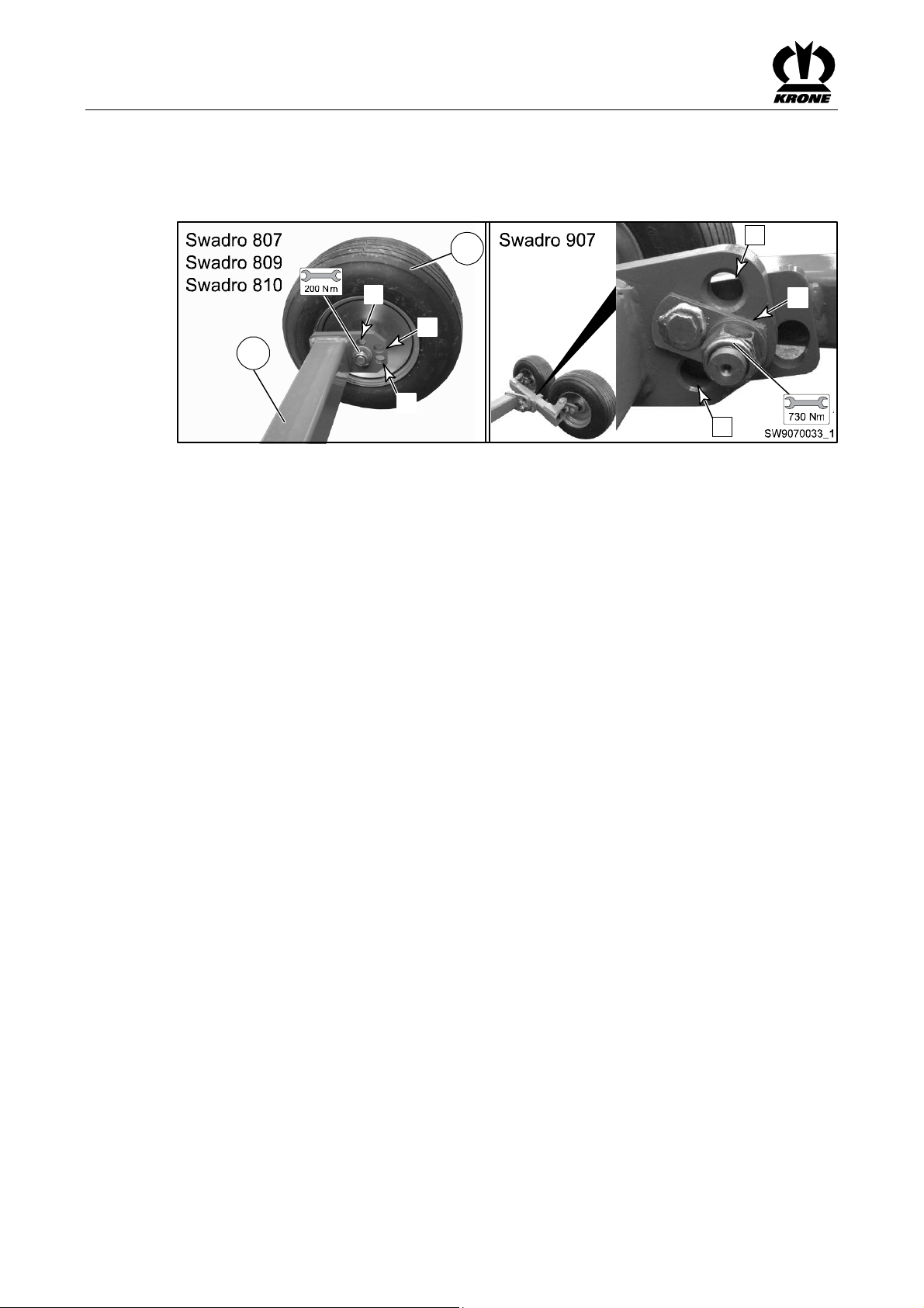
Settings
Pos:22/Ü berschriften/Überschriften 1/A-E/Einstellungen @0\mod_1199868783 862_78.doc@ 36141
9 Settings
Pos:23.1/Üb erschriften/Überschriften 2/K-O/Kreiselfahrwerk einstellen @2\mod_12028 82031680_78.doc@ 62105
9.1 To adjust the rotor running gear
Pos:23.2/B A/Einstellungen/Schwader/Kreiselfahr werk/KreiselfahrwerkBild Swadro 907BJ.2010 @76\mod_130 9772944845_78.doc@ 664458
Pos:23.3/B A/Einstellungen/Schwader/Kreiselfahr werk/KreiselfahrwerkTe xtallgemein @2\mod_1202 882266696_78.doc@ 62162
Figure 37
The transverse inclination (in direction of travel) and the longitudinal inclination (rotor tip
forwards) of the rotors can be adjusted at the rear guide wheels of the right and left running
Pos:23.4/B A/Einstellungen/Schwader/Kreiselfahr werk/KreiselfahrwerkQ uerneigung@ 2\mod_1202883118852_78.doc @6218 1
gear.
Transverse inclination:
In order to achieve an optimal operating result, the transverse inclination (in direction of travel)
for the right and left rotors can be adjusted individually at the rear guide wheels of the relevant
Pos:23.5/B A/Einstellungen/Schwader/Kreiselfahr werk/QuerneigungSei tenschwadSW 807_810@ 2\mod_1202897228493_7 8.doc@6 2307
running gear (left + right).
When a side swath is loaded, the right guide wheel must be positioned lower than the left guide
Pos:23.6/B A/Einstellungen/Schwader/Kreiselfahr werk/Kreiselfahrwerkvorg ehensweiseSadro 807_810 @2\mod_1202883960 133_78.doc@ 62219
wheel relative to the rotor running gear.
Do not walk under the raised rotors.
• Raise the rotor arms only far enough to be able to perform the switching task.
Pos:23.7/B A/Einstellungen/Schwader/Kreiselfahr werk/KreiselfahrwerkL ängsneigungSwadro 807/810 @2\mod_1202883301 211_78.doc@ 62200
• Remove the rear guide wheels and reinstall them in the desired position.
Longitudinal inclination:
2
1
I
I
II
III
III
II
The longitudinal inclination can be changed (rotor tips forward) by reconnecting the rear guide
wheels (right and left) of the running gear in positions (I,II,III).
Pos. I= least tipping effect
Pos:23.8/B A/Einstellungen/Schwader/Kreiselfahr werk/Kreiselfahrwerkvorg ehensweiseSadro 807_810 @2\mod_1202883960 133_78.doc@ 62219
Pos. III= most tipping effect
Do not walk under the raised rotors.
• Raise the rotor arms only far enough to be able to perform the switching task.
Pos:24/BA/-- ---Seitenumbruch------ @0\mod_119617531 1226_0.doc@ 4165
• Remove the rear guide wheels and reinstall them in the desired position.
62
Page 63

Pos:25/Ü berschriften/Überschriften 2/F-J/Fahrtrichtungr egulieren@ 36\mod_1263299717731_78.doc @33870 2
9.2 Regulating direction of travel
Pos:26/BA/ Einstellungen/Schwader/Fahrtrichtung regulieren SW807/810/907 @75\mo d_1309505120074_78.doc @663715
3
1
Fig. 38
If the rotary rake is not running in the centre behind the tractor on a level street, this can be
controlled by adjusting the lengthways suspension arms (1) or the two track control arms (2).
• Loosen the counter nut (3).
• Adjust the track control arm.
Pos:27/BA/-- ---Seitenumbruch------ @0\mod_119617531 1226_0.doc@ 4165
• Tighten counter nut (3).
Settings
2
3
SW810027
63
Page 64

Settings
Pos:28.1/Üb erschriften/Überschriften 2/A-E/EinstellbareD rosseln@ 0\mod_1197295892260_78.doc @17199
9.3 Adjustable throttles
Pos:28.2/B A/Sicherheit/Gefahrenhinweise/Einstell arbeitengezogene Maschinen@ 0\mod_1199717 011038_78.doc@ 33980
Danger! - Unexpected movements of the machine
Effect: Danger to life or serious injuries.
• Setting tasks must only be performed when the drive is switched off and the engine is at
a standstill!
• Switching off the engine
• Remove the ignition key.
• Secure the machine against the possibility of rolling back.
Pos:28.3/B A/Einstellungen/Drossel/Drosseln einstellenallge meinerText SW807_810 _907@1 6\mod_1234866857148_78.doc @197079
You can use the adjustable throttles to adjust the lowering speeds of the rotors on the machine.
The throttles are set in the factory so that the rotor is lowered into the headland position or out
of the headland position into the working position with a time delay (front, rear).
To allow for different types of tractors and oil pressures, the throttles may need to be
readjusted.
Pos:28.4/B A/Einstellungen/Drossel/Hinweis Einstellunga ndenDr osseln(Auswirkung) @7\mo d_1215525223776_78.doc @103417
Note
Adjustment on the throttles
Even the smallest adjustments to the stud bolts or throttle setting screws may significantly
change the lifting and lowering speed.
Pos:28.5/B A/Einstellungen/Drossel/Hinweis Sechskantmutter/Imbusschr aubekontern @7\mod_1215 525389308_78.doc@ 103437
Pos:28.6/B A/Einstellungen/Drossel/Drossel 3Bild SW807_810 _907@1 6\mod_1234865985835_78.doc @197028
Pos:28.7/B A/Einstellungen/Drossel/Drossel (3)hinterer Kreisel@ 7\mod_12155236009 01_78.doc@ 103377
Pos:29/BA/-- ---Seitenumbruch------ @0\mod_119617531 1226_0.doc@ 4165
Note
Adjustment on the throttles
After an adjustment has been made to the throttles, lock the hexagonal nuts and Allen head
screw. Then test functionality.
3
c/d
SW9070030
Fig. 39
Throttle 3
Lowering speed of the rear rotor.
• Loosen hexagonal socket head screw (c).
• Screw stud screw (d) in or out (unscrewing it increases the flow of oil and thus increases
the speed at which the rear rotor is lowered.)
64
Page 65

Pos:30.1/Üb erschriften/Überschriften 1/U-Z/Wartung@ 0\mod_1199883581050 _78.doc@ 36685
10 Maintenance
Pos:30.2/Üb erschriften/Überschriften 2/P-T/SpezielleSic herheitshinweise@ 0\mod_1196660495760_7 8.doc@9 134
10.1 Special Safety Instructions
Pos:30.3/B A/Sicherheit/Gefahrenhinweise/Lad ewagen/GefahrWartung allgemein @0\mod_1199884 069862_78.doc@ 36704
Danger! - When performing repair, maintenance or cleaning work on the machine, or in
the case of technical intervention, drive elements may start moving.
Effect: Danger to life, injuries or damage to the machine.
• Switch off the tractor engine and remove the ignition key
• Secure the machine and tractor against the possibility of rolling back.
• Switch off the PTO and disengage it
• After the repair, maintenance and cleaning work or technical interventions are completed,
mount all protective coverings and safety devices properly again.
• Avoid skin contact with oils, greases, cleaning agents and solvents.
• In the event of injuries or burns due to oils, cleaning agents or solvents, contact a
physician immediately.
• All other safety instructions must also be followed to avoid injuries and accidents.
Pos:30.4/Üb erschriften/Überschriften 2/A-E/Entlastungsfeder(n) @2\mod_12035 08983876_78.doc@ 66384
10.2 Compensation Spring(s)
Pos:30.5/B A/Sicherheit/Gefahrenhinweise/Mähw erke/Einstellungan denEntlast ungsfedern@ 0\mod_1196751594562_78.doc @12 575
Danger! - Setting on the compensation springs
Effect: Danger to life or serious injuries
• The compensation springs must only be removed in transport position. In the working
position the compensation springs are subject to high tensile stress.
• Severe injury can be caused if the compensation springs are removed while in the
working position.
• The lower threaded blocks on the compensation springs must be fully screwed in.
Pos:30.6/Üb erschriften/Überschriften 2/P-T/Probelauf@ 0\mod_1196782963921 _78.doc@ 14908
10.3 Test run.
Pos:30.7/B A/Sicherheit/Gefahrenhinweise/Mähw erke/Verwendungvon nichtzug elassenenErsatzteilen @0\ mod_1196783037140_78.doc @14946
Danger! - Using non-approved spare parts.
Effect: Danger to life, serious injuries or loss of warranty claims as well as exclusion of liability
• Use only authentic KRONE spare parts and accessories authorised by the manufacturer.
The use of spare parts, accessories or additional equipment not manufactured, tested or
approved by KRONE will exclude any liability for consequential damage.
Maintenance
Pos:30.8/B A/Wartung/HinweisV erschleissverringern @0\mod_1 199953505303_78.doc@ 37204
Pos:30.9/B A/-----Seitenumbruch------ @0\mod_1196175 311226_0.doc@ 4165
Note
To ensure problem-free operation of the machine and to reduce wear and tear, specific
maintenance and upkeep intervals must be observed. These include cleaning, greasing,
lubricating and oiling parts and components.
65
Page 66

Maintenance
A
Pos:30.10/Ü berschriften/Überschriften 2/A-E/Anzugsdrehmomente @45\mod_ 1277103093968_78.doc @410970
10.4 Tightening Torques
Pos:30.11/ BA/Wartung/Drehmomente /Anzugsmomente/Dr ehmomente@ 45\mod_1277102920578_7 8.doc@4 10945
The tightening torque MA is stated in Nm
(unless otherwise indicated).
5.6 6.8 8.8 10.9 12.9
Ø
M 4
M 5
M 6
M 8
M 10
M12
M14
M14x1.5
M 16
M16x1.5
M 20
M 24
M 24x1.5
M 24x2
M 27
M 27x2
M30
29 37 49 72 84
42 64 85 125 145
350
A = Thread size
(The stability class can be seen on the head of the
screw.)
MA (Nm)
2.2 3 4.4 5.1
4.5 5.9 8.7 10
7.6 10 15 18
18 25 36 43
100 135 200 235
145 215 255
160 210 310 365
225 330 390
425 610 710
730 1050 1220
800 1150 1350
1100 1550 1800
1150 1650 1950
1450 2100 2450
Pos:30.12/ BA/Wartung/Mutternu ndSchrauben (50h)anziehen @0\ mod_1196949864530_78.doc @15293
Pos:30.13/ BA/-----Seitenumbruch------ @0\mod_119617 5311226_0.doc@ 4165
NOTE
The table above does not apply to countersunk screws with a hexagonal socket head if the
countersunk screw is tightened with the hexagonal socket head.
Note
Regularly check that nuts and bolts are tightly in place (approx. every 50 hours) and tighten
them if necessary.
66
Page 67
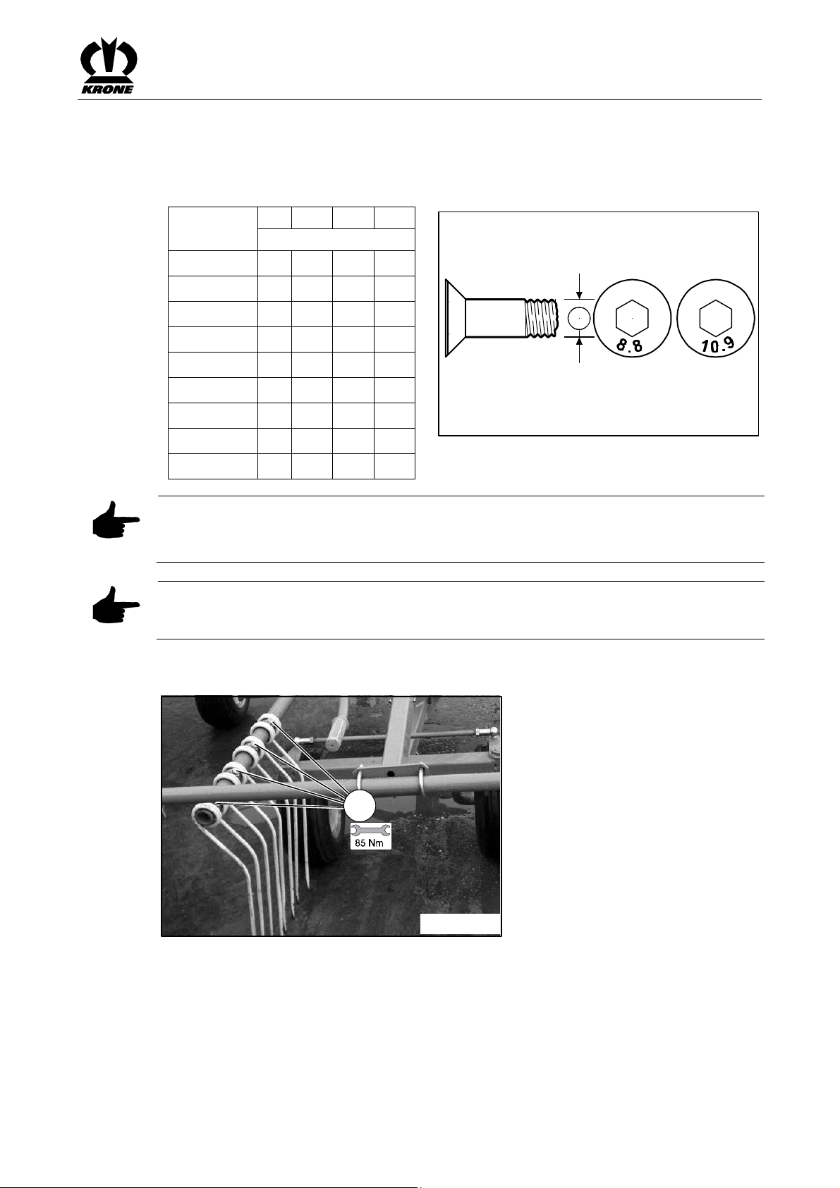
Pos:30.14/Ü berschriften/Überschriften 2/A-E/Anzugsdrehmomente überInnensechs kant@ 45\mod_1277106415765_78.doc @411230
A
10.5 Tightening Torques (Countersunk Screws)
Pos:30.15/ BA/Wartung/Drehmomente /Anzugsmomente/Dr ehmomenteüber Innensechskant @45\mod_12771 06232328_78.doc@ 411205
The tightening torque MA is stated in Nm
(unless otherwise indicated).
5.6 8.8 10.9 12.9
Ø
M 4
M 5
M 6
M 8
M 10
M 12
M 14
M 16
M 20
MA (Nm)
2.5 3.5 4.1
4.7 7 8
8 12 15
20 29 35
23 39 58 67
34 68 100 116
108 160 188
168 248 292
340 488 568
Maintenance
A = Thread size
(The stability class can be seen on the head of the
screw.)
A
BM 400 0234
NOTE
The table above applies only to countersunk screws with hexagonal socket heads and metric
threading that are tightened by the hexagonal socket head.
Pos:30.16/ BA/Wartung/Mutternu ndSchrauben (50h)anziehen @0\ mod_1196949864530_78.doc @15293
Note
Regularly check that nuts and bolts are tightly in place (approx. every 50 hours) and tighten
them if necessary.
Pos:30.17/ BA/Wartung/Schwader/Zinkenarme/Prü fender Schraubenan denZinken @2\mod_ 1202748503095_78.doc @61240
10.6 Testing the screws on the tines
1
SW700030
Figure 40:
The tine screws (1) must be retightened to the specified tightening torque after they have been
Pos:30.18/ BA/-----Seitenumbruch------ @0\mod_119617 5311226_0.doc@ 4165
used the first time.
67
Page 68

Maintenance
Pos:30.19.1/Ü berschriften/Überschriften 2/P-T/Reifen@ 0\mod_1197357995667 _78.doc@ 18075
10.7 Tyres
Pos:30.19.2/ BA/Sicherheit/Gefahrenhinweise/Fals cheReifenmontage @0\mod _1197358162433_78.doc@ 18132
Warning! - Tyre fitting incorrect
Effect: Injuries or damage to the machine
• Fitting tyres requires sufficient knowledge and the availability of proper tools!
• If tyres are not correctly fitted, it could explode when pumped up. This can cause serious
injury. If you do not have sufficient experience of fitting tyres, have tyres fitted by the
KRONE dealer or a qualified tyre specialist.
• When fitting tyres on the wheel rims, the maximum pressure given by the tyre
manufacturer must not be exceeded. The tyre or even the wheel rim could explode
and/or burst.
• If the tyre heels do not fit properly when the maximum permitted pressure is reached, let
out the air, align tyres, lubricate the tyre heels and pump up the tyre again.
• Detailed information about how to fit tyres onto agricultural machinery can be obtained
from the tyre manufacturers.
Pos:30.19.3/Ü berschriften/Überschriften 3/P-T/Reifenprü fenund pflegen@ 0\mod_1197358037214_78.doc @18094
10.7.1 Checking and maintaining tyres
Pos:30.19.4/ BA/Wartung/Reifen/Reihenfolge Reifenmontage @0\mod_119995 4083131_78.doc@ 37321
1
3
10
Pos:30.19.5/ BA/-----Seitenumbruch------ @0\mod_11961 75311226_0.doc@ 4165
5
7
9
2
Figure 41
When loosening and tightening the wheel nuts, observe the order indicated in the illustration. 10
operating hours after they have been mounted, check the wheel nuts and retighten them if
necessary. After that, check them every 50 operating hours to make certain they are tight.
Check the tyre pressure at regular intervals and refill if necessary. The tyre pressure depends
on the size of the tyres. The values are listed in the table.
8
6
4
KLWOA-02
68
Page 69

Pos:30.19.6/ BA/Wartung/Reifen/Schwader/Anzie hdrehmomentder Räderam Fahrwerk @2\mod_12027948 44888_78.doc@ 61315
10.7.2 Torque of wheels on the running gear
Maintenance
SW700040
Pos:30.19.7/ BA/Wartung/Reifen/Reifen-Luftdruc kallgemein @0\mod_11999568 52616_78.doc@ 37365
Figure 42
10.7.3 Tyre air pressure
Check the tyre pressure at regular intervals and refill if necessary. The tyre pressure depends
Pos:30.19.8/ BA/Wartung/Reifen/Schwader/Reif en-LuftdruckTabelle Schwader80 7_810_907@ 27\mod_1245994740600_78.d oc@2 64718
on the size of the tyres. The values are listed in the table.
Tyre identification Tyre pressure [bar]
16x6.50-8 4PR 1.8
4PR10.0/75-15.3 8PR 1.0
15/55-17 10PR (Swadro 907) 2.0
Pos:30.19.9/ BA/Wartung/Reifen/Anziehdrehmo ment@0\ mod_1199955905460_78.doc @37340
Tightening Torque
Threading Key size inmmNumber of bolts
M12 x 1.5 19 4/5 95 Nm 95 Nm
M14 x 1.5 22 5 125 Nm 125 Nm
M18 x 1.5 24 6 290 Nm 320 Nm
M20 x 1.5 27 8 380 Nm 420 Nm
Max. tightening torque
per hub -
pieces
black galvan.
Pos:30.20/ BA/-----Seitenumbruch------ @0\mod_119617 5311226_0.doc@ 4165
M20 x 1,5 30 8 380 Nm 420 Nm
M22 x 1.5 32 8/10 510 Nm 560 Nm
M22 x 2 32 10 460 Nm 505 Nm
69
Page 70

Maintenance
Pos:30.21.1/ Abkürzungen/Abkürz ungensprachneutral/Sc hwader/Swadro807 /Swadro 809/ Swadro 810@76 \mod_1309772465864_0.doc @664398
Pos:30.21.2/Ü berschriften/Überschriften 2/A-E/Austausch derZinkenarme (imReparaturf all)@ 36\mod_126285464629 7_78.doc@ 338320
10.8 Replacing the tine arms(in case of repair)
Pos:30.21.3/ BA/Wartung/Schwader/Zinkenarme/ Austauschder Zinkenarme(i mReparaturfall) Bildaußer SW907_1000 @3\ mod_1204871743515_78.doc@ 73425
Swadro 807 / Swadro 809 / Swadro 810
2
1
3
Pos:30.21.4/ BA/-----Seitenumbruch------ @0\mod_11961 75311226_0.doc@ 4165
Fig. 43
6
SW700041
70
Page 71

Pos:30.21.5/ BA/Wartung/Schwader/Zinkenarme/ KLebender Zinkenarme@ 3\mod_1204276891493_7 8.doc@7 0234
Maintenance
In case of repairs, the tine arms can be removed and replaced individually.
• Unscrew the screws (1) of the tine arm
• Loosen the bolts (2) on the nearby tine arms
• Remove the tine arm (3) and replace the faulty components
Note
The tine arms (3) are glued together with the control arm shafts (4). To be able to loosen the
components from each other, the connecting point must be heated up (to about 300 degrees).
• When a new tine arm (3) /control arm shaft (4) is installed, these two parts must be glued
to each other before installation with high-strength adhesive.
• Apply glue (high-strength) (Part No. 939 042 0) on the front of the control arm shaft (4).
• Mount the tine arm (3) and secure with clamping sleeves (5).
• While installing the tine arm, make certain that the cam follower roller is inserted into the
running track of the cam track.
Note
The cam follower roller is securely inserted into the running track when barely any play can be
observed in the motion of the tine arm.
Pos:30.21.6/ BA/-----Seitenumbruch------ @0\mod_11961 75311226_0.doc@ 4165
• Tighten all bolts to the required torque (105 Nm).
Caution!
Turn the rotor once around 360 degrees manually. The rotor must move easily. If it does not,
the tine arms are not installed correctly. The error must be eliminated so that the rotor can turn
easily.
71
Page 72

Maintenance
Pos:30.21.7/ Abkürzungen/Abkürz ungensprachneutral/Sc hwader/Swadro907 @1\mod_ 1202226168013_0.doc@ 58250
Pos:30.21.8/Ü berschriften/Überschriften 2/A-E/Austausch derZinkenarme (imReparaturf all)@ 36\mod_126285464629 7_78.doc@ 338320
10.9 Replacing the tine arms(in case of repair)
Pos:30.21.9/ BA/Wartung/Schwader/Zinkenarme/ Austauschder Zinkenarme(i mReparaturfall) BildSW 907_1000@ 16\mod_123494081645 9_78.doc@ 197222
Swadro 907
2
1
2
2
4
Pos:30.21.10 /BA/-----Seitenumbruch------ @0\mod_1196 175311226_0.doc@ 4165
Fig. 44
6
1
3
1
3
3
SW9070032
72
Page 73

Pos:30.21.11 /BA/Wartung/Schwader/Zinkenar me/Klebender ZinkenarmeSW 907_1000@ 16\mod_12348863 59835_78.doc@ 197162
Maintenance
In the case of repair, the tine arms can be individually replaced by dismantling them.
• Unscrew the bolts (1) of two tine arms.
• Loosen the bolts (2) on the nearby tine arms.
• Pull out two time arms (3) together by about 200 mm.
• Pull the faulty tine arm out completely and replace the faulty components.
Note
The tine arms (3) are glued together with the control arm shafts (4). To be able to loosen the
components from each other, the connecting point must be heated up (to about 300 degrees).
• When a new tine arm (3) / control arm shaft (4) is installed, these two parts must be glued
to each other before installation with high-strength adhesive.
• Apply glue (high-strength) (Part No. 939 042 0) on the front of the control arm shaft (4).
• Mount the tine arm (3) and secure with clamping sleeves (5).
• While installing two tine arms, install them together (make certain that the follower rollers
are inserted into the running track of the cam track).
Note
The follower roller is securely inserted in the running track when no play is noted with the
movement of the tine arms.
Pos:30.22/ BA/-----Seitenumbruch------ @0\mod_119617 5311226_0.doc@ 4165
• Tighten all bolts to the required torque (105 Nm).
Caution!
Turn 1x rotor 360 degrees manually. The rotor should turn smoothly. If this is not the case, the
tine arms have not been installed as instructed. The fault must be remedied so that rotor can be
turned smoothly.
73
Page 74

Maintenance – lubrication chart
Pos:30.23.1/Ü berschriften/Überschriften 1/U-Z/Wartung- Schmierplan @0\mod_1197 359304198_78.doc@ 18232
11 Maintenance – lubrication chart
Pos:30.23.2/Ü berschriften/Überschriften 2/P-T/SpezielleSi cherheitshinweise@ 0\mod_119666049576 0_78.doc@ 9134
11.1 Special Safety Instructions
Pos:30.23.3/ BA/Sicherheit/Gefahrenhinweise/La dewagen/GefahrWartu ngallgemein @0\mod_119988 4069862_78.doc@ 36704
Danger! - When performing repair, maintenance or cleaning work on the machine, or in
the case of technical intervention, drive elements may start moving.
Effect: Danger to life, injuries or damage to the machine.
• Switch off the tractor engine and remove the ignition key
• Secure the machine and tractor against the possibility of rolling back.
• Switch off the PTO and disengage it
• After the repair, maintenance and cleaning work or technical interventions are completed,
mount all protective coverings and safety devices properly again.
• Avoid skin contact with oils, greases, cleaning agents and solvents.
• In the event of injuries or burns due to oils, cleaning agents or solvents, contact a
physician immediately.
• All other safety instructions must also be followed to avoid injuries and accidents.
Pos:30.23.4/ BA/-----Seitenumbruch------ @0\mod_11961 75311226_0.doc@ 4165
74
Page 75

Pos:30.23.5/Ü berschriften/Überschriften 2/F-J/Gelenkwelle @0\mod_1199781 879794_78.doc@ 34542
11.2 PTO shaft
Pos:30.23.6/ Abkürzungen/Abkürz ungensprachneutral/Sc hwader/Swadro807 /Swadro 809/ Swadro 810@76 \mod_1309772465864_0.doc @664398
Pos:30.23.7/ BA/Wartung/Schwader/Schmierpl an/AbschmierenGelen kwelleSchwader SW700_800_9 00@7 8\mod_1313496485928_78.doc @691600
Swadro 807 / Swadro 809 / Swadro 810
Fig. 45
Lubricate the PTO shafts at the intervals indicated in the drawing with a multi-purpose grease.
Pos:30.23.8/ Abkürzungen/Abkürz ungensprachneutral/Sc hwader/Swadro907 @1\mod_ 1202226168013_0.doc@ 58250
Pos:30.23.9/ BA/Wartung/Schwader/Schmierpl an/AbschmierenGelen kwelleSchwader @2\mod_12027 98437998_78.doc@ 61395
Follow the operating instructions of the PTO shaft manufacturer.
Swadro 907
Maintenance – lubrication chart
Pos:30.23.10 /BA/-----Seitenumbruch------ @0\mod_1196 175311226_0.doc@ 4165
Figure 46
Lubricate the PTO shafts at the intervals indicated in the drawing with a multi-purpose grease.
Follow the operating instructions of the PTO shaft manufacturer.
75
Page 76

Maintenance – lubrication chart
Pos:30.23.11 /Überschriften/Überschriften 1/U-Z/Wartung- Schmierplan @0\mod_119 7359304198_78.doc@ 18232
12 Maintenance – lubrication chart
Pos:30.23.12 /BA/Wartung/Hinweisa usGründen derÜbersicht @2\mod _1202799283498_78.doc@ 61453
Note
To make the illustration easier to read, the greasing points have only been shown on one side
of the machine. The greasing same points are present on the other side of the machine (mirrorimage).
Pos:30.23.13 /BA/-----Seitenumbruch------ @0\mod_1196 175311226_0.doc@ 4165
76
Page 77

Pos:30.23.14 /Überschriften/Überschriften 2/P-T/Schmierplan @0\mod_1197361 829026_78.doc@ 18495
12.1 Lubrication Chart
Pos:30.23.15 /Abkürzungen/Ab kürzungensprachneutral/ Schwader/Swadro807 /Swa dro809/ Swadro8 10@7 6\mod_1309772465864_0.doc @664398
Pos:30.23.16 /BA/Wartung/Schwader/Schmierpla n/SchmierplanSwadro 807_809_810 @76\mod_13097 73690657_78.doc@ 664524
Swadro 807 / Swadro 809 / Swadro 810
Maintenance – lubrication chart
Pos:30.23.17 /BA/-----Seitenumbruch------ @0\mod_1196 175311226_0.doc@ 4165
Fig. 47
77
Page 78

Maintenance – lubrication chart
Pos:30.23.18 /Abkürzungen/Ab kürzungensprachneutral/ Schwader/Swadro907 @1\ mod_1202226168013_0.doc @58250
Pos:30.23.19 /BA/Wartung/Schwader/Schmierpla n/SchmierplanSwadro 907@ 76\mod_1309777324924 _78.doc@ 664608
Swadro 907
Pos:30.24/ BA/-----Seitenumbruch------ @0\mod_119617 5311226_0.doc@ 4165
78
Fig. 48
Page 79

Pos:30.25.1/Ü berschriften/Überschriften 1/U-Z/Wartung- Hydr aulik@2\ mod_1203057943713_78.doc @64474
13 Maintenance - hydraulic system
Pos:30.25.2/ BA/Sicherheit/Hydraulik/Arbeiten ander Hydraulikanlage @0\mod_119727 9394885_78.doc@ 17063
Danger! - Caution with leaking lines
Effect: Danger to life, injuries or damage to the machine.
• When searching for leaks, use suitable aids, always use suitable tools and wear
protective goggles to avoid the risk of injury!
• Escaping high-pressure fluids can penetrate the skin and cause serious injury. Therefore,
you must depressurise the system before disconnecting lines.
• Hydraulic oil escaping from a small opening can barely be seen. Because of this you
should use a piece of cardboard or something similar when searching for leaks. Protect
your hands and body.
• If any fluid penetrates the skin, it must be removed immediately by a doctor who is
familiar with this kind of injury; serious infections could otherwise result. Physicians who
are not familiar with this area should consult appropriate information from a competent
medical source.
• Check the hydraulic hose lines at regular intervals and replace them if damaged or worn!
The replacement lines must comply with the requirements of the device manufacturer.
• Ensure that all line connections are tight before the pressure in the system builds up
again.
• Repair work on the hydraulic system must only be performed by authorised KRONE
professional workshops.
Maintenance - hydraulic system
Pos:30.25.3/ BA/Sicherheit/Hydraulik/Hydrauli kschlauchleitungenunterlieg eneiner Alterung@ 2\mod_1202746238361_78.doc @610 83
Pos:30.26/ BA/-----Seitenumbruch------ @0\mod_119617 5311226_0.doc@ 4165
Danger! - Hydraulic hose lines are subject to ageing
Effect:
The characteristics of the lines change depending on pressure, heat load and the effect of UV
rays.
The date of manufacture appears on the hydraulic hoses. This way the age can be ascertained
quickly.
By law the hydraulic lines must be replaced after six years.
Use original spare parts when replacing hydraulic hoses!
79
Page 80

Maintenance - Gearbox
Pos:30.27/Ü berschriften/Überschriften 1/U-Z/Wartung- Getriebe@ 2\mod_12030582028 23_78.doc@ 64495
14 Maintenance - Gearbox
Pos:30.28/Ü berschriften/Überschriften 2/F-J/Füllmengen undSchmiermittelbezeic hnungender Getriebe@ 0\mod_1196951094046_78.d oc@ 15335
14.1 Filling Quantities and Lubrication Designations for Gearboxes
Pos:30.29/ BA/Wartung/Tabellen/Schwader/Ta belleFüllmengen fürSchwader 807/810/907@ 2\mod_120274678 6580_78.doc@ 61102
Filling
quantity
Filtered oils
[litres] Brand name Brand name
Oil change Bio-degradable
lubricants
Rotor gear
0.5 l
Transfer gearbox front rear
Pos:30.30.1/ BA/Wartung/Ölkontrolle_Wechsel/Sc hwader/Kreiselgetriebe/Kreiselgetrie be/KreiselgehäuseSW 807/810/907/700/800/900/ 1010@ 2\mod_1202798994920_78.doc @61434
0.5 l SAE 90
14.2 Rotor gear / rotor housing
2
Fig. 49
Pos:30.30.2/ BA/-----Seitenumbruch------ @0\mod_11961 75311226_0.doc@ 4165
The rotor gear (1) and rotor housing (2) are maintenance-free
Fluid gear grease
GFO 35
1
SW700021
Permanently
lubricated
with grease
approx.
1000 ha
On request
80
Page 81

Pos:30.30.3.1 /Überschriften/Überschriften 2/U-Z/Verteilergetriebe vorneund hinten@ 2\mod_1202747368314_7 8.doc@ 61123
14.3 Transfer gearbox front and rear
Pos:30.30.3.2 /BA/Wartung/Ölkontrolle_Wechsel/ Schwader/Hinweisder Ölwechsel anden Getriebenmuss inArbeitsposi tionerfolgen. @2\mod_120274 8334517_78.doc@ 61221
Note
The oil in the gearboxes must be changed in working position.
Pos:30.30.3.3 /BA/Wartung/Ölkontrolle_Wechsel/ Schwader/Verteilergetriebe/Verteilergetr iebeBild SW807/810/907 @2\mod_1 202747609142_78.doc@ 61142
Maintenance - Gearbox
Pos:30.30.3.4 /BA/Wartung/Ölkontrolle_Wechsel/ ÖlwechselVersion6 Schwader@ 2\mod_120299133 6702_78.doc@ 64084
Pos:30.30.3.5 /BA/Wartung/Ölkontrolle_Wechsel/ Ölqualität/Ölmenge: sieheKa pitel@ 0\mod_119700785948 6_78.doc@ 15531
Pos:30.30.3.6 /BA/Wartung/Ölkontrolle_Wechsel/ Altölordnungsgemäß entsorgen @0\mod_1197008117 002_78.doc@ 15550
1
1
2
2
SW810030_1
Fig. 50
Oil change:
• For time intervals see Chapter "Lubricant quantities and designations for gearboxes".
• Unscrew oil drain plug (2).
• Collect oil in a suitable drip pan.
• Screw oil drain plug (2).
• Top up the oil (1).
Oil quality / oil quantity: see Chapter "Filling Quantities and Lubricant Designations for
Gearboxes"
Note
The used oil must be disposed of correctly
SW810031_1
Pos:31/BA/-- ---Seitenumbruch------ @0\mod_119617531 1226_0.doc@ 4165
81
Page 82

Special equipment
Pos:32.1/Üb erschriften/Überschriften 1/P-T/Sonderausstattung @2\mod_120 2808469779_78.doc@ 61649
15 Special equipment
Pos:32.2/B A/Sicherheit/Gefahrenhinweise/Einstell arbeitengezogene Maschinen@ 0\mod_1199717 011038_78.doc@ 33980
Danger! - Unexpected movements of the machine
Effect: Danger to life or serious injuries.
• Setting tasks must only be performed when the drive is switched off and the engine is at
a standstill!
• Switching off the engine
• Remove the ignition key.
• Secure the machine against the possibility of rolling back.
Pos:32.3/B A/Sonderausstatung/Schwader/Zinke nverlustsicherung@ 2\mod_1202806976420_ 78.doc@ 61592
15.1 Tine loss safeguard
5
1
3
4
Pos:32.4/B A/-----Seitenumbruch------ @0\mod_1196175 311226_0.doc@ 4165
2
KS-0-098
Figure 51
Mounting the tine loss safeguard
The tine loss safeguard for the double coil spring tines consists of:
• a cable
• two cable clamps
• two coach bolts, washers and lock nuts each
Secure the cable (1) with the cable clamps (2) onto the rotor tines (3).
Note
Thecable must be located behind the rotor tine in relation to the direction of rotation. The nuts
(4) of the cable clamps must face outwards.
Spare tine loss safeguards Order No. : 153 479 0
82
Page 83

Pos:32.5/B A/Sonderausstatung/Schwader/Kette zurTief enbegrenzungder Unterlenker@ 2\mod_12028081272 95_78.doc@ 61611
15.2 Chain for height restriction of suspension arms
4
1
2
3
Figure 52
• Secure chains (1) with a spring-type slotted straight pin (3) and a washer (2) at the
suspension arm seats.
• Attach chain hooks (4) to the tractor.
• Select chain length according to desired max. lowering level.
Special equipment
Pos:33/BA/-- ---Seitenumbruch------ @0\mod_119617531 1226_0.doc@ 4165
Note
Spare tine loss safeguards Order No. : 153 479 0
Chain for height restriction of suspension arms Order No.: 250 759 0
83
Page 84

Placing in Storage
Pos:34.1/Üb erschriften/Überschriften 1/A-E/Einlagerung@ 0\mod_11973854591 20_78.doc@ 19966
16 Placing in Storage
Pos:34.2/Üb erschriften/Überschriften 2/P-T/SpezielleSic herheitshinweise@ 0\mod_1196660495760_7 8.doc@9 134
16.1 Special Safety Instructions
Pos:34.3/B A/Sicherheit/Gefahrenhinweise/Lad ewagen/GefahrWartung allgemein @0\mod_1199884 069862_78.doc@ 36704
Danger! - When performing repair, maintenance or cleaning work on the machine, or in
the case of technical intervention, drive elements may start moving.
Effect: Danger to life, injuries or damage to the machine.
• Switch off the tractor engine and remove the ignition key
• Secure the machine and tractor against the possibility of rolling back.
• Switch off the PTO and disengage it
• After the repair, maintenance and cleaning work or technical interventions are completed,
mount all protective coverings and safety devices properly again.
• Avoid skin contact with oils, greases, cleaning agents and solvents.
• In the event of injuries or burns due to oils, cleaning agents or solvents, contact a
physician immediately.
• All other safety instructions must also be followed to avoid injuries and accidents.
Pos:34.4/B A/-----Seitenumbruch------ @0\mod_1196175 311226_0.doc@ 4165
84
Page 85

Pos:34.5/Üb erschriften/Überschriften 2/A-E/AmEnde derErnt esaison@0 \mod_1197385501276_78.doc @19985
16.2 At the End of the Harvest Season
Pos:34.6/B A/Einlagerung/Schwader/Einlagerung allgemein @2\mod_1202808 984326_78.doc@ 61669
Before placing the machine in winter storage, clean the outside thoroughly. If you use a highpressure cleaner to do this Do not keep a stream of water directed at bearing points. After
cleaning is completed, lubricate all lubrication points. Do not wipe off any grease that comes out
of bearing points. The hardened grease will provide additional protection against moisture.
Check all movable components such as deflector rollers, joints, tension rollers, etc. to make
certain they move easily. If necessary remove, clean, grease and remount. If necessary, replace
with new parts.
Use only original KRONE replacement parts.
Disassemble the PTO shaft. Lubricate the inner tubes and the guard tube with grease. Grease
the lubrication points on the cross joint and grease the bearing rings of the guard tube.
Repair places with damaged paint and preserve all bare metal places thoroughly with rust
protection agent.
Park the machine in a dry location, but not in the vicinity of artificial fertilisers or livestock
buildings. Repair places with damaged paint and preserve all bare metal places thoroughly with
rust protection agent.
Caution!
Placing in Storage
Pos:34.7/B A/-----Seitenumbruch------ @0\mod_1196175 311226_0.doc@ 4165
The machine should only be placed on blocks with a suitable vehicle lifting device. Make
certain that the machine is stable and safe when it is on blocks.
To provide relief for the tyres, set the machine on blocks. Protect the tyres against external
influences such as oil, grease, direct sunlight , etc.
Perform the necessary repair tasks during the time immediately after the harvest season. Draw
up a list of all replacement parts you will need. This will make it easier for your KRONE dealer to
process your orders and you will be certain that your machine will be ready for use at the
beginning of the next season.
85
Page 86

Placing in Storage
Pos:34.8/Üb erschriften/Überschriften 2/U-Z/VorBeginn derneue nSaison@ 0\mod_119738602 4448_78.doc@ 20081
16.3 Before the Start of the New Season
Pos:34.9/Üb erschriften/Überschriften 2/P-T/SpezielleSic herheitshinweise@ 0\mod_1196660495760_7 8.doc@9 134
16.4 Special Safety Instructions
Pos:34.10/ BA/Sicherheit/Gefahrenhinweise/La dewagen/GefahrWartung allgemein @0\mod_119988 4069862_78.doc@ 36704
Danger! - When performing repair, maintenance or cleaning work on the machine, or in
the case of technical intervention, drive elements may start moving.
Effect: Danger to life, injuries or damage to the machine.
• Switch off the tractor engine and remove the ignition key
• Secure the machine and tractor against the possibility of rolling back.
• Switch off the PTO and disengage it
• After the repair, maintenance and cleaning work or technical interventions are completed,
mount all protective coverings and safety devices properly again.
• Avoid skin contact with oils, greases, cleaning agents and solvents.
• In the event of injuries or burns due to oils, cleaning agents or solvents, contact a
physician immediately.
• All other safety instructions must also be followed to avoid injuries and accidents.
Pos:34.11/ BA/Einlagerung/Schwader/Vor derSaisaon @ 2\mod_1202809277951_78.d oc@ 61689
• Lubricate the machine thoroughly. Remove any condensation water which may have
collected in the bearings.
• Check oil level in the gearbox(es) and top up if necessary.
• Check hydraulic hoses and lines for leaks and replace them where necessary.
• Check the air pressure in the tyres and refill if necessary.
• Check all screws to make certain they are tight or retighten them if necessary.
• Check all electrical connection cables and the lighting. Repair or replace it if necessary.
• Check all settings on the machine and correct if necessary.
• Re-read the operating instructions thoroughly.
Pos:35/BA/-- ---Seitenumbruch------ @0\mod_119617531 1226_0.doc@ 4165
Note
Use vegetable oils and greases.
86
Page 87

Pos:36.1/Üb erschriften/Überschriften 1/P-T/Störungen- Ursachen undBehebung @0\mod_120 0296925180_78.doc@ 39459
17 Malfunctions - Causes and Remedies
Pos:36.2/Üb erschriften/Überschriften 2/P-T/SpezielleSic herheitshinweise@ 0\mod_1196660495760_7 8.doc@9 134
17.1 Special Safety Instructions
Pos:36.3/B A/Sicherheit/Gefahrenhinweise/Lad ewagen/GefahrWartung allgemein @0\mod_1199884 069862_78.doc@ 36704
Danger! - When performing repair, maintenance or cleaning work on the machine, or in
the case of technical intervention, drive elements may start moving.
Effect: Danger to life, injuries or damage to the machine.
• Switch off the tractor engine and remove the ignition key
• Secure the machine and tractor against the possibility of rolling back.
• Switch off the PTO and disengage it
• After the repair, maintenance and cleaning work or technical interventions are completed,
mount all protective coverings and safety devices properly again.
• Avoid skin contact with oils, greases, cleaning agents and solvents.
• In the event of injuries or burns due to oils, cleaning agents or solvents, contact a
physician immediately.
• All other safety instructions must also be followed to avoid injuries and accidents.
Pos:36.4/B A/-----Seitenumbruch------ @0\mod_1196175 311226_0.doc@ 4165
Malfunctions - Causes and Remedies
87
Page 88

Malfunctions - Causes and Remedies
Pos:36.5/B A/Störungen- Ursachenund Behebung/Schwader/T abellarischeAuflistung Schwader 807/810/907@ 2\mod_1202809825498_78.doc @6 1750
Malfunction Possible cause Remedy
Rotor not working neatly Raking height set too high Set raking height lower
The working speed is too high. Reduce the driving speed. Rough
estimate 8-10 km/h. For uneven
terrain and/or higher amount of
forage, it may be necessary to
drive slower.
Speed is too low Increase the speed. Rough guide
450 rpm
Side rotor inclination set
incorrectly
Change side inclination setting
(see section on Operation "Side
Inclination Setting of Rotor
Running Gear").
Tine arm(s) crooked Replace tine arms
High level of forage contamination Raking height set too low Set raking height higher
Tine arm(s) bent Replace tine arms
Swath width too large Working width too large Change working width.
Speed is too low Increase speed
One rotor goes down in headland
position, the other goes up
Rotor not swivelled up into
headland position
Activate the hydraulics until the
rotor arms are resting against the
stops.
Not possible to adjust rotor to
unevenness in the ground
Setting of raking height - electrical
not working
Transfer from front to rear rotor
for single swath not neat.
Tractor's lower suspension arm
set too high or too low
Tractor hydraulics not in float
position
Align frame horizontally (high
steerable pinions about 63 cm)
Set tractor hydraulics to float
position.
Fuse defective Replace the fuse in the switch box
that is screwed onto the frame.
Front swath cloth is set in position
for two single swaths.
Switch swath cloth to position for
one side swath (see section on
Operation "Switching from Two
Individual Swaths to One Side
Swath").
Pos:37/BA/-- ---Seitenumbruch------ @0\mod_119617531 1226_0.doc@ 4165
88
Width adjustment cylinder not
completely retracted.
Continue activating the doubleaction hydraulics until the width
adjustment cylinder is completely
retracted.
Page 89

Pos:38/Ü berschriften/Überschriften 1/A-E/Anhang@ 1\mod_1202278612285_78 .doc@ 58360
18 Appendix
Pos:39/BA/ Anhang/Schwader/Im Anhangfinden Sieden Schaltplan@ 2\mod_1202811415263 _78.doc@ 61821
=====Ende derStückliste =====
The circuit diagram can be found in the Appendix.
Appendix
89
Page 90

22
123
123
S3 Arbeitshöhe Links S4 Arbeitshöhe Rechts
01
01
ab
rechts
8765
2
auf
rechts
/1²
/1²/1²
X4/6X4/2
X4/7
X4/3
/2.5² /2.5²
M2
1 2
rechts
stellen
höhe einArbeitsM2 =
0303-274-0
Schaltplan SW ohne Einzel.
ab
links
/1²
1 13 3
2
auf
links
X4/8
X4/9
X4/11
X4/10
/2.5² /2.5²
M1
1 2
links
stellen
höhe einArbeitsM1 =
Albers24/01/03
1N4007
2
1
S1 S3 S4
11
9 10
Ein-Aus
Steckdose
am Drei-
punktbock
X1
X4/1
X4/5
X4/4
Platine für
Motorschaltung
X2
/2.5²
15/30 31
1 2
(NEU MIT 6179 )
Batterie
von der
Masse
Batterie
1 2
von der
+12V
/1²/1²/1²
L
J K E F G H
/2.5²
Steckdose
3polig
am Drei-
punktbock
Page 91

A
Adjustable throttles.............................................64
Adjusting the lower suspension arms.................28
Adjusting the raking height mechanically ...........49
Adjusting the Rear Swath Cloth..........................41
Information Required for Questions and Orders.. 8
Install the PTO shaft .......................................... 36
Intended Use........................................................ 9
Introduction .......................................................... 7
L
Affixing the Adhesive Safety and Information
Labels .............................................................15
At the End of the Harvest Season......................85
B
Before the Start of the New Season...................86
C
Chain for height restriction of suspension arms .83
Checking and maintaining tyres .........................68
Commissioning ...................................................27
Compensation Spring(s).....................................65
Connecting the electrical controls.......................35
Connecting the hydraulic lines............................33
Contact................................................................15
D
Dangers in Case of Non-compliance with the
Safety Instructions..........................................20
Driving and Transport.........................................37
F
Filling Quantities and Lubrication Designations for
Gearboxes ......................................................80
First installation...................................................27
From transport into working position ..................40
Lighting connection............................................ 34
Lowering the rotor arms into working position... 40
Lubrication Chart................................................ 77
M
Maintenance ................................................25, 65
Maintenance - hydraulic system ........................ 79
Maintenance – lubrication chart................... 74, 76
Malfunctions - Causes and Remedies...............87
Mounting onto the Tractor.................................. 31
Move the hoop guards to the working position.. 48
Move the hoop guards to transport position. ..... 53
O
Operation ........................................................... 39
Overload protection............................................ 39
P
Parking............................................................... 61
Personnel Qualification and Training................. 20
Placing in Storage.............................................. 84
Position of the Adhesive Safety Stickers on the
Machine .........................................................16
Position of the General Information Labels on the
Machine .........................................................18
H
Height of tractor lower suspension arms............30
Hitched Implements............................................22
Hydraulic system ................................................24
Hydraulics...........................................................32
I
Identification Plate ................................................7
Identifying Symbols in the Operating Instructions
........................................................................19
Inadmissible Modes of Operation.......................26
90
PTO operation.................................................... 23
PTO shaft..................................................... 29, 75
Purpose of Use.................................................... 7
R
Regulating direction of travel ............................. 63
Removing the tine protections from the tine tips 40
Re-Ordering the Adhesive Safety and Information
Labels ............................................................15
Replacing the tine arms(in case of repair)... 70, 72
Page 92

S
Test run.............................................................. 65
Safety..................................................................14
Safety Instructions and Accident Prevention
Regulations.....................................................21
Safety Instructions on the Machine ....................26
Safety-conscious work practices ........................20
Settings...............................................................62
Special equipment..............................................82
Start-up...............................................................31
Switching from working position to transport
position............................................................53
Swivel tine arms to working position...................46
Swivelling tine arms into transport position ........54
T
Technical data ......................................................9
Tightening Torque.............................................. 69
Tightening Torques............................................ 66
Tightening Torques (Countersunk Screws)....... 67
Tine loss safeguard............................................ 82
To adjust the rotor running gear ........................62
Travelling on an incline......................................52
Tyres............................................................24, 68
U
Unauthorised Conversion/Modification and Spare
Parts Production ............................................26
W
Working in the vicinity of power transmission lines
.......................................................................26
91
Page 93

Page 94

. . . konsequent, kompetent
Maschinenfabrik
Bernard Krone GmbH
Heinrich-Krone-Straße 10, D-48480 Spelle
Postfach 11 63, D-48478 Spelle
Phone +49 (0) 59 77/935-0
Fax +49 (0) 59 77/935-339
Internet: http://www.krone.de
eMail: info.ldm@krone.de
 Loading...