

Krone EasyCut 7540, EasyCut 9140 CV, EasyCut 9140 Shift, EasyCut 9140 CV Collect, EasyCut 10000 Shift Operating Instructions Manual

Disc Mower
<v>T-Typ1</v>
EasyCut 7540
</v>
<v>T-Typ2</v>
EasyCut 9140 Shift
<v>T-Typ3</v>
EasyCut 9140 CV
<v>T-Typ4</v>
EasyCut 9140 CV Collect
<v>T-Typ5</v>
EasyCut 10000 Shift
(
<v>T-abMasch.-Nr.</v>
from serial no.
<v>T-Bestell-Nr.</v>
Order no.
</v>
: 150 000 005 04 en
</v>
: 819 340)
</v>
</v>
</v>
</v>
<v>B-Titelbild</v> </v>
Or i g i n a l o p e r a t i n g i n s t r u c t io n s
29.06.2011

Table of Contents
Pos:1/BA /Konformitätserklärungen/EasyCut/Ne uab20 10/EasyCut7540/9140/ 10000@ 53\mod_1290074054218_78.doc @508675
CV0
EC Declaration of Conformity
We, Maschinenfabrik Bernard Krone GmbH
Heinrich-Krone-Str. 10, D-48480 Spelle
hereby declare as manufacturer of the product named below, on our sole responsibility,
that the
Machine: Krone disc mower
Type / Types: EasyCut 7540 : EasyCut 9140 Shift ; EasyCut 10000 Shift
EasyCut 9140 CV; EasyCut 9140 CV Collect
to which this declaration refers is in compliance with the relevant provisions of
EC Directive 2006/42/EC (Machinery)
The signing Managing Director is authorised to compile the technical documents.
Spelle, 01.12.10
Dr.-Ing. Josef Horstmann
(Managing Director, Design and Development)
Year of manufacture: Machine No.:
Pos:2/BA /Vorwort/Sehrgeehrter Kunde@ 0\mod_11956263003 26_78.doc@ 905
Dear customer,
Dear customer,
You have now received the operating instructions for the KRONE
product which you have purchased.
These operating instructions contain important information for the
proper use and safe operation of the machine.
If these operating instructions should become wholly or partially
unusable, you can obtain replacement operating instructions for
your machine by stating the number given overleaf.
Pos:3/BA /-----Seitenumbruch------ @0\mod_1196175311 226_0.doc@ 4165
2

Table of Contents
Pos:4/Üb erschriften/Überschriften 1/F-J/Inhaltsverzeichnis@ 31\mod_12519699 52727_78.doc@ 302165
1 Table of Contents
Pos:5/BA /InhaltsverzeichnisSpr achenneutral@ 10\mod_1221574899104_0.doc @135 495
1 Table of Contents...................................................................................................................................3
2 Foreword .................................................................................................................................................7
3 Introduction.............................................................................................................................................8
3.1 Purpose of Use.................................................................................................................................. 8
3.2 Validity............................................................................................................................................... 8
3.2.1 Contact........................................................................................................................................... 8
3.3 Identification Plate .............................................................................................................................9
3.4 Information Required for Questions and Orders................................................................................ 9
3.5 Intended Use ...................................................................................................................................10
3.6 Technical data .................................................................................................................................10
4 Safety.....................................................................................................................................................12
4.1 Identifying Symbols in the Operating Instructions ........................................................................... 12
4.2 Identification of the hazard warnings............................................................................................... 12
4.2.1 Personnel Qualification and Training Fehler! Textmarke nicht definiert...................................... 13
4.2.2 Dangers in Case of Non-compliance with the Safety Instructions............................................... 13
4.2.3 Safety-conscious work practices .................................................................................................13
4.3 Safety Instructions and Accident Prevention Regulations............................................................... 14
4.4 Attached devices .............................................................................................................................15
4.5 PTO operation .................................................................................................................................16
4.6 Hydraulic system .............................................................................................................................17
4.7 Tyres................................................................................................................................................ 17
4.8 Maintenance.................................................................................................................................... 18
4.9 Unauthorised Conversion/Modification and Spare Parts Production .............................................. 19
4.10 Inadmissible Modes of Operation.................................................................................................... 19
4.11 Working in the vicinity of power transmission lines ......................................................................... 19
4.12 Introduction......................................................................................................................................20
4.13 Position of the Adhesive Safety Stickers on the Machine ............................................................... 20
4.14 Position of the General Information Labels on the Machine............................................................ 24
4.14.1 Re-Ordering the Adhesive Safety and Information Labels......................................................27
4.14.2 Affixing the Adhesive Safety and Information Labels..............................................................27
5 Commissioning.....................................................................................................................................28
5.1 First installation................................................................................................................................ 28
5.2 Special Safety Instructions ..............................................................................................................28
5.3 Mounting onto the Tractor................................................................................................................ 29
5.3.1 Clutching points ...........................................................................................................................29
5.4 Setting the coupling rod................................................................................................................... 30
5.5 PTO shaft......................................................................................................................................... 31
5.5.1 Length adjustment .......................................................................................................................31
3

Table of Contents
6 Start-up..................................................................................................................................................33
6.1 Mounting onto the Tractor................................................................................................................ 33
6.2 Hydraulics........................................................................................................................................ 34
6.2.1 Special Safety Instructions ..........................................................................................................34
6.2.2 Connecting the hydraulic lines..................................................................................................... 34
6.3 Connecting the electrical controls.................................................................................................... 36
6.4 Lighting............................................................................................................................................ 37
6.5 Lighting connection.......................................................................................................................... 37
6.6 PTO shaft......................................................................................................................................... 38
6.6.1 Special Safety Instructions ..........................................................................................................38
6.6.2 Install the PTO shaft.................................................................................................................... 39
6.7 Intermediate PTO shaft.................................................................................................................... 39
6.8 Swivelling parking support into transport position ........................................................................... 40
7 Driving and Transport..........................................................................................................................41
7.1 Switching from working position to transport position .....................................................................41
7.1.1 Checking the transport interlock.................................................................................................. 43
8 Operation...............................................................................................................................................44
8.1 Function of the switches on the control unit .................................................................................... 45
8.2 From transport into working position ............................................................................................... 46
8.3 Before mowing................................................................................................................................. 47
8.3.1 Folding down the Safety Device.................................................................................................. 48
8.4 Swivelling parking support into transport position ........................................................................... 49
8.4.1 Adjusting the lateral suspension arm........................................................................................... 50
8.5 Headland Position............................................................................................................................ 51
8.6 Detaching the machine.................................................................................................................... 53
8.7 Parking............................................................................................................................................. 54
9 Settings .................................................................................................................................................55
9.1 Adjusting the cutting height.............................................................................................................. 55
9.2 Adjust overcut..................................................................................................................................56
9.3 Adjust overcut..................................................................................................................................57
9.4 Adjusting the Guards....................................................................................................................... 58
9.4.1 Lateral guards..............................................................................................................................58
9.4.2 Front guards................................................................................................................................. 59
9.5 Adjusting the Compensation Springs .............................................................................................. 60
9.6 Adjustable throttles .......................................................................................................................... 61
9.7 Adjusting the Tedder Speed............................................................................................................ 62
9.8 Adjusting the conditioner plate ........................................................................................................ 63
9.9 Setting of the pole protection mechanism ....................................................................................... 64
9.10 Adjusting the swath width................................................................................................................ 65
9.10.1 Adjustment for Swathing..........................................................................................................65
4

Table of Contents
9.10.2 Wide spreading........................................................................................................................66
9.10.3 Wide spreading with the "Cross Conveyor" option.................................................................. 67
10 Maintenance..........................................................................................................................................69
10.1 Special Safety Instructions ..............................................................................................................69
10.1.1 Test run.................................................................................................................................... 69
10.2 Spare Parts...................................................................................................................................... 70
10.3 Tightening Torques..........................................................................................................................70
10.4 Tightening Torques (Countersunk Screws)..................................................................................... 71
10.4.1 Deviating Torque ..................................................................................................................... 71
10.5 Filling Quantities and Lubrication Designations for Gearboxes....................................................... 72
10.5.1 Oil Level Check and Oil Change Intervals (Gearboxes)..........................................................72
10.6 Main gearbox...................................................................................................................................73
10.7 Speed gearbox ................................................................................................................................74
10.8 Mower Drive Gearbox...................................................................................................................... 75
10.9 Oil level check and oil change on the cutter bar.............................................................................. 76
10.9.1 Oil change................................................................................................................................ 76
10.9.2 Checking the oil level............................................................................................................... 76
10.10 Checking the Cutter Blades and Blade Holder............................................................................ 78
10.10.1 Cutter Blades...........................................................................................................................78
10.10.2 Blade screw connection...........................................................................................................79
10.10.3 Blade Quick-Fit Device ............................................................................................................80
10.10.4 Periodical Inspection of the Leaf Springs ................................................................................81
10.10.5 Periodical Inspection of the Cutting Discs / Blade Drums ....................................................... 82
10.10.6 Abrasion Limit..........................................................................................................................83
10.11 Blade Changing on Cutting Discs................................................................................................ 84
10.11.1 Blade Screw Connection .........................................................................................................85
10.11.2 Blade Quick-Fit Device ............................................................................................................86
10.12 Replacing the linings....................................................................................................................87
10.13 Rotary hub with shear fuse (optional).......................................................................................... 88
10.13.1 After Shearing Off....................................................................................................................92
11 Maintenance – lubrication chart .........................................................................................................94
11.1 Special Safety Instructions ..............................................................................................................94
11.2 PTO shaft.........................................................................................................................................95
11.3 Lubrication Chart .............................................................................................................................96
12 Placing in Storage................................................................................................................................98
13 Before the Start of the New Season ...................................................................................................99
13.1 Special Safety Instructions ..............................................................................................................99
13.2 Test run............................................................................................................................................99
13.3 Friction Clutch................................................................................................................................101
14 Special equipment..............................................................................................................................102
5

Table of Contents
14.1 Special Safety Instructions ............................................................................................................102
14.2 Adjusting Skids .............................................................................................................................. 102
14.3 Cross conveyor..............................................................................................................................103
14.4 Safety Instructions on the Machine ............................................................................................... 103
14.5 Position of the Adhesive Safety Stickers on the Cross Conveyor................................................. 104
14.6 Position of the General Information Labels on the Cross Conveyor ............................................. 106
14.7 General..........................................................................................................................................107
14.7.1 Hydraulics.............................................................................................................................. 107
14.7.2 Lowering the cross conveyor belts ........................................................................................ 107
14.7.3 Speed control of transport belts............................................................................................. 108
14.8 Setting Conveyor Belt.................................................................................................................... 109
14.9 Bar on cross conveyor is bent .......................................................................................................109
14.10 Hydraulic system........................................................................................................................110
14.10.1 Filling Quantities and Lubricant Designations ....................................................................... 110
14.10.2 Oil Tank.................................................................................................................................. 111
14.10.3 Checking the oil level............................................................................................................. 112
14.10.4 Oil change.............................................................................................................................. 112
14.10.5 Replacing the hydraulic oil filter............................................................................................. 113
15 Appendix .............................................................................................................................................114
15.1 Hydraulic System Circuit Diagrams............................................................................................... 114
15.1.1 Without cross conveyor belt...................................................................................................114
15.1.2 With cross conveyor belt........................................................................................................114
15.2 Electrical circuit diagram................................................................................................................ 115
Pos:6/BA /-----Seitenumbruch------ @0\mod_1196175311 226_0.doc@ 4165
6

Pos:7.1/Ü berschriften/Überschriften 1/U-Z/Vorwort@ 0\mod_1195627720123 _78.doc@9 82
2 Foreword
Pos:7.2/ BA/Vorwort/EasyCut/Verehrter KundeEasyCut @3\mo d_1204546394934_78.doc @70529
Dear Customer!
By purchasing the disc mower, you have acquired a quality product made by KRONE.
We are grateful for the confidence you have invested in us in buying this machine.
To be able to use the disc mower optimally, please read these operating instructions thoroughly
before you start using the machine.
The contents of this manual are laid out in such a way that you should be able to perform any
task by following the instructions step by step. It contains extensive notes and information about
maintenance, how to use the machine safely, secure working methods, special precautionary
measures and available accessories. This information and these instructions are essential,
important and useful for the operational safety, reliability and durability of the disc mower.
Pos:7.3/ BA/Vorwort/EasyCut/Weiterer VerlaufEasyCut @3\mo d_1204546850246_78.doc @70549
Note
In the operating instructions which follow, the disc mower will also be referred to as the
"machine".
Pos:7.4/ BA/Vorwort/BeachtenSie fürMasc hine@ 0\mod_1195626904076_78.doc @944
Please note:
Foreword
Pos:8/BA /-----Seitenumbruch------ @0\mod_1196175311 226_0.doc@ 4165
The operating instructions are part of your machine.
Only operate this machine after you have been trained to do so and according to these
instructions.
It is essential to observe the safety instructions!
It is also necessary to observe the relevant accident prevention regulations and other generally
recognised regulations concerning safety, occupational health and road traffic.
All information, illustrations and technical data in these operating instructions correspond to the
latest state at the time of publication.
We reserve the right to make design changes at any time and without notification of reasons.
Should you for any reason not be able to use these operating instructions either wholly or
partially, you can receive a replacement set of operating instructions for your machine by
quoting the number supplied overleaf.
We hope that you will be satisfied with your KRONE machine.
Maschinenfabrik Bernard Krone GmbH
Spelle
7

Introduction
Pos:9.1/ BA/Einleitung/Einleitung@ 0\mod_1195562498 677_78.doc@ 416
3 Introduction
These operating instructions contain fundamental instructions. These must be observed in
operation and maintenance. For this reason, these operating instructions must be read by
operating personnel before commissioning and use, and must be available for easy reference.
Follow both the general safety instructions contained in the section on safety and the specific
safety instructions contained in the other sections.
Pos:9.2/ BA/Einleitung/EasyCut/Einleitung ZusatzEC 7540/9140 @11\mod_122362413 8988_78.doc@ 148393
These operating instructions describe the rear combination only. Separate operating
Pos:9.3/Ü berschriften/Überschriften 2/U-Z/Verwendungszweck @1\mod_120 1707246738_78.doc@ 54055
3.1 Purpose of Use
Pos:9.4/ BA/Einleitung/EasyCut/Verwendungszwec kMäher @3\mod_12045474 95418_78.doc@ 70590
Pos:9.5/ BA/Einleitung/Gültigkeit/EasyCut /EasyCut7540/ 9140/10000@ 53\mod_1290076123328_78.d oc@50 8702
3.2 Validity
Pos:9.6/Ü berschriften/Überschriften 3/A-E/Ansprechpartner@ 0\mod_1195569 394286_78.doc@ 839
3.2.1 Contact
Pos:9.7/ Adressen/AdresseMaschi nenfabrikKRONE Spelle@ 0\mod_1195568531083_7 8.doc@ 734
instructions are available for the front mowing unit and must also be taken into consideration.
The EasyCut disc mower is used for cutting crops growing on the ground (except maize).
These operating instructions apply to disc mowers of the series:
EasyCut 7540, EasyCut 9140 Shift, EasyCut 9140 CV, EasyCut 9140 CV Collect,
EasyCut 10000 Shift
Pos:9.8/ BA/-----Seitenumbruch------ @0\mod_11961753 11226_0.doc@ 4165
Maschinenfabrik Bernard Krone GmbH
Heinrich-Krone-Strasse 10
D-48480 Spelle (Germany)
Telephone: + 49 (0) 59 77/935-0 (Head Office)
Fax.: + 49 (0) 59 77/935-339 (Head Office)
Fax.: + 49 (0) 59 77/935-239 (Spare parts - domestic)
Fax.: + 49 (0) 59 77/935-359 (Spare parts - export)
Email: info.ldm@krone.de
8

Pos:9.9/Ü berschriften/Überschriften 2/K-O/Kennzeichnung @0\mod_119556462 2099_78.doc@ 496
3.3 Identification Plate
Pos:9.10/B A/Einleitung/Kennzeichnung/EasyCut /KennzeichnungEas yCut7540/9140 @11\mod_12232 82911050_78.doc@ 145253
1
Fig. 1
Introduction
EC800001
Pos:9.11/B A/Einleitung/Angabenf ürAnfrage undBestellungen_M aschnr.@ 9\mod_1220507505930_78.doc @1261 10
The machine data are specified on the type plate (1). It is attached to the carrying bar.
3.4 Information Required for Questions and Orders
Year
Mach. No.
Type
Note
The entire identification plate represents a legal document and should not be altered or
rendered illegible!
When asking questions concerning the machine or ordering spare parts, be sure to provide type
designation, machine number and the year of manufacture of the relevant machine: To ensure
that these data are always available, we recommend that you enter them in the fields above.
Note
Authentic KRONE spare parts and accessories authorised by the manufacturer help to ensure
safety. The use of spare parts, accessories or additional equipment not manufactured, tested or
approved by KRONE will exclude any liability for consequential damage.
Pos:9.12/B A/-----Seitenumbruch------ @0\mod_1196175 311226_0.doc@ 4165
9

Introduction
Pos:9.13.1 /Überschriften/Überschriften 2/A-E/Bestimmungsgemäßer Gebrauch@ 0\mod_119640154 5090_78.doc@ 7728
3.5 Intended Use
Pos:9.13.2 /BA/Einleitung/Bestimmungsgemäßer Gebrauch/EasyCut/Bes timmungsgemäßerGe brauch(Einzahl) @3\mod_12 04548357809_78.doc@ 70671
Pos:9.13.3 /BA/Einleitung/Bestimmungsgemäßer Gebrauch/Nicht bestimmungsg emäss@ 0\mod_1196401324340_78.doc @7690
Pos:9.14/B A/Einleitung/TechnischeD aten@ 0\mod_1195566374865_78.doc @594
3.6 Technical data
Pos:9.15/A bkürzungen/Abkürzu ngensprachneutral/Eas yCut/EasyCut7540/914 0@11\m od_1223453159866_0.doc @146591
Pos:9.16/B A/Einleitung/TechnischeD aten/EasyCut/EasyCut 7540/9140@ 11\mod_1223283005566_ 78.doc@ 145275
wa
The disc mower is built exclusively for customary use in agricultural work (intended use).
Any use of the machine for other purposes is deemed not to be in accordance with intended
use. The manufacturer shall not be liable for any resulting damage; the user alone shall bear
the risk.
Operation in accordance with intended use also includes observing the operating, maintenance
and service instructions specified by the manufacturer.
Unauthorised modifications to the machine may affect the properties of the machine or disrupt
proper operation. For this reason, unauthorised modifications shall exclude any liability of the
manufacturer for consequential damage.
All information, illustrations and technical data in these operating instructions correspond to the
latest state at the time of publication. We reserve the right to make design changes at any time
and without notification of reasons.
(EasyCut 7540, EasyCut 9140)
Type Easy Cut
EasyCut
EasyCut
Pos:9.17/B A/-----Seitenumbruch------ @0\mod_1196175 311226_0.doc@ 4165
7540
9140 Shift
9140 CV
Working width [mm] 7410 8700 8700
Transport width [mm] 2900 2900 2800
Number of mowing discs 8 10 10
Number of mower drums 4 4 4
Conditioner system - - V-shaped
prong
Speed of the conditioner [rpm] - - 600/900
Width of conditioner system [rpm] - - 2x 2500
Acreage [ha/h] 8.0 – 10.0 9.0 – 10.0 9.0 – 10.0
Power consumption [kW/HP] 74 / 100 110 / 150 147 / 200
PTO speed [rpm] 1000 1000 1000
Hydraulic connections
required
2 x single-
action*
2 x single-
action*
2 x single-
action*
Service weight [kg] approx. 1400 approx. 1600 approx. 2620
*) EW= Single-action control unit
10

Pos:9.18/A bkürzungen/Abkürzu ngensprachneutral/Eas yCut/EasyCut10000 Shift@ 41\mod_1271851241507_ 0.doc@ 373499
Pos:9.19/B A/Einleitung/TechnischeD aten/EasyCut/EasyCut 10000Shift @53\mod_12 90077653765_78.doc @508729
wa
Introduction
(EasyCut 10000 Shift)
Type Easy Cut
10000 Shift
Working width [mm] 9300 - 9600
Transport width [mm] 3000
Number of mowing discs 12
Number of mower drums 4
Conditioner system Speed of the conditioner [rpm] Width of conditioner system [rpm] Acreage [ha/h] 10,0 – 11,0
Power consumption [kW/HP] 110 / 150
PTO speed [rpm] 1000
Pos:10/BA/-- ---Seitenumbruch------ @0\mod_119617531 1226_0.doc@ 4165
Hydraulic connections
required
2 x single-
action*
Service weight [kg] approx. 1960
*) EW= Single-action control unit
11

Safety
Pos:11.1/Üb erschriften/Überschriften 1/P-T/Sicherheit@ 0\mod_11955667486 46_78.doc@ 635
4 Safety
Pos:11.2/B A/Sicherheit/Kennzeichnung vonHinweise ninder Betriebsanleitung Einführungstext @0\ mod_1195637804826_78.doc @1098
4.1 Identifying Symbols in the Operating Instructions
The safety instructions contained in this manual which could result in personal injury if not
Pos:11.3/B A/Sicherheit/Kennzeichnung derGefahrenhi nweise@ 28\mod_1250244370070_78.doc @274714
4.2 Identification of the hazard warnings
followed are identified by the general danger sign:
Danger!
DANGER! - Type and source of the hazard!
Effect: Danger to life or serious injuries.
• Measures for hazard prevention
Warning !
WARNING! - Type and source of the hazard!
Effect: Injuries, serious material damage.
• Measures for hazard prevention
Caution!
Pos:11.4/B A/Sicherheit/AllgemeineF unktionshinweise @0\m od_1196869714452_78.doc @15185
Pos:11.5/B A/-----Seitenumbruch------ @0\mod_1196175 311226_0.doc@ 4165
CAUTION! - Type and source of the hazard!
Effect: Property damage
• Measures for risk prevention.
General function instructions are indicated as follows:
Note!
Note - Type and source of the note
Effect: Economic advantage of the machine
• Actions to be taken
Instructions which are attached to the machine need to be followed and kept fully legible.
12

Pos:11.6.1 /BA/Sicherheit/Personalqualifikation und-Schulung @0\mod_1195639 383185_78.doc@ 1136
4.2.1 Personnel Qualification and Training Fehler! Textmarke nicht definiert.
The machine may be used, maintained and repaired only by persons who are familiar with it
and have been instructed about the dangers connected with it. The operator must define areas
of responsibility and monitoring of personnel. Should personnel lack the required knowledge,
they must receive the required training and instruction. The operator must ensure that the
contents of these operating instructions have been fully understood by personnel.
Repair work not described in these operating instructions should only be performed by
Pos:11.6.2 /BA/Sicherheit/Gefahren beiNichtbeachtung derSicher heitshinweise@ 0\mod_1195639434013_78 .doc@ 1155
authorised service centres.
4.2.2 Dangers in Case of Non-compliance with the Safety Instructions
Failure to follow the safety instructions could result in personal injury and environmental
hazards as well as damage to the machine. If the safety instructions are not respected, this
could result in the forfeiture of any claims for damages.
Failure to follow the safety instructions could result, for example, in the following hazards:
• Endangering of persons due to not protected working areas.
• Breakdown of important machine functions
• Failure of prescribed methods for repair and maintenance
• Endangering of persons due to mechanical and chemical effects
Pos:11.6.3 /BA/Sicherheit/Sicherheitsbewußtes Arbeiten@ 0\mod_11956397925 76_78.doc@ 1174
• Damage to the environment due to leaking hydraulic oil
4.2.3 Safety-conscious work practices
Safety
Pos:11.6.4 /BA/-----Seitenumbruch------ @0\mod_119617 5311226_0.doc@ 4165
Always observe the safety instructions set out in these operating instructions, all existing
accident prevention rules and any internal work, operating and safety rules issued by the
operator.
The safety and accident prevention regulations of the responsible professional associations are
binding.
The safety instructions provided by the vehicle manufacturer should also be observed.
Observe the applicable traffic laws when using public roads.
Be prepared for emergencies. Keep the fire extinguisher and first aid box within reach. Keep
emergency numbers for doctors and fire brigade close to the telephone.
13

Safety
Pos:11.6.5 /BA/Sicherheit/Sicherheits- undUnfallverhütu ngs-VorschriftenSwadro _Ladewagen_EasyCut@ 73\mod_1308298589 597_78.doc@ 655493
4.3 Safety Instructions and Accident Prevention Regulations
1 Please follow all generally applicable safety and accident prevention regulations in
addition to the safety instructions contained in these operating instructions!
2 The attached warning and safety signs provide important information for safe operation.
Pay attention to these for your own safety!
3 When using public roads, make sure to observe the applicable traffic regulations!
4 Make sure that you are familiar with all equipment and controls as well as with their
functions before you begin working with the machine. It is too late to learn this when you
are using the machine for work!
5 The user should wear close fitting clothes. Avoid wearing loose or baggy clothing.
6 Keep the machine clean to prevent the danger of fire!
7 Before starting or moving the machine, make certain that nobody is in the vicinity of the
machine! (Watch for children!) Make sure that you have a clear view!
8 Carrying passengers during operation and transport on the working implement is not
permitted.
9 Couple implements correctly! Attach and secure implements to specified devices only!
10 When attaching or detaching implements, place the supporting devices in the correct
positions!
11 Use extreme caution when attaching or detaching implements onto or from the tractor!
12 Always attach ballast weights properly to the fixing points provided!
13 Observe permitted axle loads, gross weight and transport dimensions!
14 Check and attach transport equipment, such as lighting, warning devices and protective
equipment!
15 Actuating mechanisms (cables, chains, linkages etc.) for remote controlled devices must
be positioned in such a way that no movements are unintentionally triggered in any
transport or working positions.
16 Ensure that implements are in the prescribed condition for on-road travel and lock them in
place in accordance with the manufacturer's instructions!
17 Never leave the driver's seat when the vehicle is moving!
18 Always drive at the correct speed for the prevailing driving conditions! Avoid sudden
changes in direction when travelling uphill or downhill or across a gradient!
19 Hitched implements and ballast weights affect the driving, steering and braking response
of the machine. Make sure that you are able to brake and steer the machine as required!
20 Take into account the extension radius and/or inertia of an implement when turning
corners!
21 Start up implements only when all safety devices have been attached and set in the
required position!
22 Keep safety equipment in good condition. Replace missing or damaged parts.
23 Keep clear of the working range of the machine at all times!
24 Do not stand within the turning and swivel range of the implement!
25 Never operate the hydraulic folding frames if anyone is inside the swivel range!
14

26 Parts operated by external power (e.g. hydraulically) can cause crushing and shearing
injuries!
27 Before leaving the tractor, lower the implement onto the ground, apply the parking brake,
Pos:11.6.6 /BA/Sicherheit/Angebaute Geräte/Geräteange bautEasyCut @3\mod_12045 52588996_78.doc@ 70752
switch off the engine and remove the ignition key!
4.4 Attached devices
1 Use extreme caution when attaching or detaching implements onto or from the tractor!
2 Couple the respective application devices to the appropriate couplings (e.g. three-point
suspension) only and secure them in a way (transport, use) that excludes inadvertent
lifting or lowering of the device.
3 When using three-point linkage, the attachment categories of the tractor and the device
(e.g. PTO speed, hydraulic system) must be coordinated!
4 When using the outside controls for the three-point linkage, do not step between the
Pos:11.6.7 /BA/-----Seitenumbruch------ @0\mod_119617 5311226_0.doc@ 4165
tractor and the device (risk of injury)!
Safety
15

Safety
Pos:11.6.8 /BA/Sicherheit/Zapfwellenbetrieb Traktor@ 0\mod_1199699899350 _78.doc@ 33264
4.5 PTO operation
1 Use only PTO shafts specified by the manufacturer!
2 The guard tube and guard cone of the PTO shaft and the PTO guard must be attached
and in good working condition (on the implement side, too)!
3 Make sure that the required tube covers are in place for PTO shafts in transport and
working position!
4 Before installing or detaching PTO shafts, disengage the PTO, switch off the engine and
remove the ignition key!
5 When using PTO shafts with an overload safety or free-running coupling which are not
shielded by the guard on the tractor, mount the overload safety or free-running coupling
on the implement side!
6 Always make sure that the PTO shaft is properly installed and secured!
7 Attach chains to prevent the PTO shaft guard from rotating with the shaft!
8 Before switching on the PTO, make sure that the selected PTO speed of the tractor
matches the permissible implement speed!
9 Before switching on the PTO shaft make sure that no person is in the danger zone of the
device!
10 Never switch on the PTO if the engine is switched off!
11 No one should be in the vicinity of the rotating PTO or PTO shaft when the PTO is in use.
12 Always switch off the PTO shaft when the angle is too large or the PTO shaft is not
required!
13 Caution! After disengaging the PTO danger due to the flywheel running on! Keep away
from the implement during this time. The machine may be worked on only if it is
completely at standstill and if the flywheel is secured by the parking brake.
14 Cleaning, lubricating or adjusting PTO driven implements or the PTO shaft only with PTO
disengaged, engine switched off and ignition key withdrawn! Secure the fly-wheel with the
parking brake.
15 Place the disconnected PTO shaft onto the support provided!
16 After detaching the PTO shaft, attach the protective cover to the PTO end!
17 If damage occurs, correct this immediately before using the implement!
Pos:11.6.9 /BA/Sicherheit/Zapfwellenbetrieb Zusatz@ 2\mod_1203524761314_7 8.doc@ 66513
Pos:11.6.10/ BA/-----Seitenumbruch------ @0\mod_11961 75311226_0.doc@ 4165
Note
The instructions of the manufacturer must be observed with regard to the PTO shaft. (separate
operating instructions)
16

Pos:11.6.11/ BA/Sicherheit/Hydraulikanlage @2\mod_12 03503691986_78.doc@ 66225
4.6 Hydraulic system
1 The hydraulic system is pressurised!
2 When connecting hydraulic cylinders and motors, make sure the hydraulic hoses are
connected as specified!
3 When connecting the hydraulic hoses to the tractor hydraulics, make sure that the
hydraulics of both the tractor and the implement have been depressurized!
4 In the case of hydraulic connections between tractor and machine, the coupling sleeves
and plugs should be marked to ensure a proper connection! If the connectors are
interchanged, the function will be reversed (e. g. raising/lowering) - Risk of accident!
5 When searching for leaks, use suitable aids to avoid the risk of injury!
6 Liquids escaping under high pressure (hydraulic oil) can penetrate the skin and cause
serious injury! Seek medical help immediately should injuries occur! Danger of infection!
7 Before working on the hydraulic system, depressurise the system and switch off the
Pos:11.6.12/ BA/Sicherheit/Hydraulikanlage ZusatzAlteru ngderH ydraulikschlauchleitungen@ 3\mod_1204552 944856_78.doc@ 70772
engine!
8 Check the hydraulic hose lines at regular intervals and replace them if damaged or worn!
The new hoses must fulfill the technical requirements set by the manufacturer of the
Pos:11.6.13/Ü berschriften/Überschriften 2/P-T/Reifen@ 0\mod_1197357995667 _78.doc@ 18075
implement!
4.7 Tyres
Pos:11.6.14/ BA/Sicherheit/Reifen@ 0\mod_1195646435 716_78.doc@ 1346
1 When working on the tyres, make sure that the implement is safely lowered and secured
against rolling (wheel chocks).
2 Installing wheels and tyres requires adequate knowledge and suitable tools!
3 Repair work on the tyres and wheels should be done by specially trained personnel using
appropriate installation tools only!
4 Check tyre pressure regularly! Inflate the tyres to the recommended pressures!
5 Check the wheel nuts periodically! Missing wheel nuts can result in a wheel falling off and
Pos:11.6.15/ BA/-----Seitenumbruch------ @0\mod_11961 75311226_0.doc@ 4165
the machine tipping over.
Safety
17

Safety
Pos:11.6.16/ BA/Sicherheit/Wartung/Wartung Mäher mitGasspeicher+ Auswechseln vonArbeitswerkzeugen @0\mod_ 1195647075607_78.doc @1442
4.8 Maintenance
1 Always make certain that the drive and the engine are switched off before doing any
repairs, maintenance or cleaning! - Remove the ignition key!
2 Regularly check that nuts and bolts are properly seated and tighten if necessary!
3 When carrying out maintenance work on a raised mowing unit, always use suitable
means to secure it against falling.
4 When replacing working tools with cutting edges, use suitable tools and gloves!
5 Oils, greases and filters must be disposed of correctly!
6 Always disconnect the power supply before working on the electrical system!
7 If protective devices and guards are subject to wear, check them regularly and replace
them in good time!
8 When performing electrical welding work on the vehicle and mounted devices, turn the
power supply off at main battery switch or disconnect generator cable and battery!
9 Replacement parts must at least comply with the technical requirements set by the
manufacturer of the implements! This is guaranteed by original KRONE spare parts!
10 Only use nitrogen for filling pneumatic accumulators - risk of explosion!
Pos:11.6.17/ BA/-----Seitenumbruch------ @0\mod_11961 75311226_0.doc@ 4165
18

Pos:11.6.18/ BA/Sicherheit/Eigenmächtiger Umbauund Ersatzteilherstellung @1\mod _1201937705539_78.doc@ 55745
4.9 Unauthorised Conversion/Modification and Spare Parts Production
Conversions or modifications of the machine are permitted only with prior consultation with the
manufacturer. Original spare parts and accessories authorised by the manufacturer help to
Pos:11.6.19/ BA/Sicherheit/Unzulässige Betriebsweisen@ 11\mod_12233576 99923_78.doc@ 145527
ensure safety. Use of other parts may void liability for resulting damage.
4.10 Inadmissible Modes of Operation
The operating safety of the delivered machine is guaranteed only when it is used as intended in
compliance with the introductory section "Intended use" of the operating instructions. The limit
Pos:11.7/B A/Sicherheit/Arbeiteni mBereich vonHochspannungsl eitungen@ 11\mod_1223357468516_78.doc @14550 5
values listed in the data charts should not be exceeded under any circumstances.
4.11 Working in the vicinity of power transmission lines
1 Always take great care when working under or in the vicinity of power transmission lines.
2 Ensure that when in operation or being transported, the machine cannot exceed a total
height of approx. 4m.
3 If there is any need to travel under overhead lines, the machine operator must request
information on the rated voltage and the minimum height of the overhead lines from the
overhead line operator.
4 Always keep the safety distances according to the table.
Safety
Pos:11.8/B A/-----Seitenumbruch------ @0\mod_1196175 311226_0.doc@ 4165
Rated voltage
Safe distance from overhead lines
kV
To 1 1
Above 1 to 110 2
Above 101 to 220 3
Above 220 to 380 4
m
19

Safety
Pos:11.9/B A/Sicherheit/EasyCut/Sicherheit EinführungE asyCut@ 3\mod_1204553763950_78.doc @70812
4.12 Introduction
The disc mower is equipped with all safety devices (protective devices). However, it is not
possible to eliminate all potential hazards on this machine as this would impair its full functional
capability. Hazard warnings are attached to the machine in the relevant areas to warn against
any dangers. The safety instructions are provided in the form of so-called warning pictograms.
Important information on the position of these safety signs and what they mean is given below!
Pos:11.10/ BA/Sicherheit/Beschädigte oderunlesbare Aufkleber@ 0\mod_11955672141 15_78.doc@ 674
Danger! - Danger zone of the machine
Effect: Danger to life or serious injuries.
• Immediately replace damaged or illegible adhesive labels.
• Following repair work, always attach appropriate adhesive safety stickers to all the
replaced, modified or repaired components.
• Never clean areas carrying an adhesive safety label using a high-pressure cleaner.
• Familiarise yourself with the statement of the warning pictograms. The adjacent text and
the selected location on the machine provide information on the special danger spots on
the machine.
Pos:11.11/Ü berschriften/Überschriften 2/K-O/Lageder Sicherheitsaufkleber ander Maschine@ 0\mod_1195634967326 _78.doc@ 1020
4.13 Position of the Adhesive Safety Stickers on the Machine
Pos:11.12/ Abkürzungen/Abkürz ungensprachneutral/E asyCut/EasyCut7540/91 40@1 1\mod_1223453159866_0.doc @146591
Pos:11.13/ BA/Sicherheit/Aufkleber/EasyCut/Sic herheitsaufkleberEas yCut7540/9140 @11\mod_122 3284394660_78.doc@ 145319
GL
(EasyCut 7540, EasyCut 9140)
Fig. 2
3*
4
3
4
5
5
5
5
2
1
6
5
5
5
5
4
3
3*
4
EC800019
20
* = EasyCut 9140 CV only

Safety
1)
The PTO speeds must not exceed 1000 rpm!
The operating pressure of the hydraulic system
must not exceed 200 bar!
939101-4
MAX.1000/min
MAX. 200 bar
2)
Before starting the machine,
read and observe the
operating instructions and
safety instructions.
Order No. 939 471-1 (1x)
Order No. 939 101-4 (1x)
3)
a) Caution: some machine parts will stay in
operation for an extended period of time
before being switched off completely. Do
not touch any moving parts of the machine.
Wait until they have come to a complete
stop.
b) Move the protective devices into position
prior to start-up.
STOP
939 410 2
a b c
c) When the machine is running, keep your
distance.
Order No. 939 576-0 Easy Cut 7540 (2x), EasyCut 9140 (2x), EasyCut 9140 CV (4x)
942 197-1
4)
When the machine is running,
keep your distance.
Order No. 942 197 1 (4x)
EasyCut 9140 CV only
6)
Keep the stipulated safe distance from power
transmission lines.
Order No. 942 293-0 (1x)
Pos:11.14/ BA/-----Seitenumbruch------ @0\mod_119617 5311226_0.doc@ 4165
942 197-1
5)
While parts are moving, never
reach into areas where there is a
risk of being crushed.
Order No. 942 196 1 (8x)
942196 -1
21

Safety
Pos:11.15/ Abkürzungen/Abkürz ungensprachneutral/E asyCut/EasyCut10000 Shift@ 41\mod_1271851241507 _0.doc@ 373499
Pos:11.16/ BA/Sicherheit/Aufkleber/EasyCut/Sic herheitsaufkleberEas yCut10000S hift@ 42\mod_1272548214052_78.doc @37922 5
2
(EasyCut 10000 Shift)
3
3
1
3
3
6
5
Fig. 3
3
5
5
5
5
5
5
3
5
EC-321-0
22

Safety
1)
The P.T.O. speeds must not exceed 1000 rpm!
The operating pressure of the hydraulic system
must not exceed 200 bar!
939101-4
MAX.1000/min
MAX. 200 bar
Order no.: 939 101-4 (1x)
3)
a) Caution: Some machine parts will stay in
operation for an extended period of time
before being switched off completely. Do
not touch any moving parts of the machine.
Wait until they have come to a complete
stop.
b) Move the protective devices into protective
position prior to start-up.
c) When the machine is running, keep your
distance.
Order no. 939 576-0 (6x)
2)
Before starting the machine,
read and follow the operating
instructions and safety
instructions.
Order no.: 939 471-1 (1x)
STOP
939 410 2
a b c
942 197-1
6)
Keep the stipulated safe distance from power
transmission lines.
Order no. 942 293-0 (1x)
Pos:11.17/ BA/-----Seitenumbruch------ @0\mod_119617 5311226_0.doc@ 4165
5)
While parts are moving, never
reach into areas where there is a
risk of being crushed.
Order no. 942 196 1 (8x)
942196 -1
23

Safety
Pos:11.18/Ü berschriften/Überschriften 2/K-O/Lageder allgemeinen Hinweisaufklebera nderMasc hine@ 0\mod_1195635067920_78.doc @1039
4.14 Position of the General Information Labels on the Machine
Pos:11.19/ Abkürzungen/Abkürz ungensprachneutral/E asyCut/EasyCut7540/91 40@1 1\mod_1223453159866_0.doc @146591
Pos:11.20/ BA/Sicherheit/Aufkleber/EasyCut/Hin weisaufkleberEasyC ut7540/9140@ 30\mod_12517062 35091_78.doc@ 294865
(EasyCut 7540, EasyCut 9140)
Fig. 4
4
3
1
2
6
5
9
6
9
1
3
4
5
8
7 7
2
8
2
2
EC800020_4
1)
27 000 241 0 (2x) 850 mm EasyCut 9140 CV
2)
942 341 0 (2x) 893 mm (EasyCut 9140 CV only)
942 320 0 (2x) 600 mm (EasyCut 9140 CV only)
942 295 0 (2x) (EasyCut 7540, EasyCut 9140)
3)
Order No. 255 498 1 (1x) with
blade screw connection
Ø 17,5 mm
min. 14 mm
80
255 498-1
3)
Order No. 255 499 2 (1x) with
quick blade release
255499-2
4)
139-888
139 888-0 139 889-0
939 567-1 (1x)
139-889
24

Safety
purga antes dela primera puesta en marcha y una
a de trabajo.
La frizione di sicurezza deve essere sottomessa ad
ftet werden
5)
924 569 0 (4x)
8)
D
D
Vor der Erstinbetriebnahmeund 1x j ährlich vor
der Ernte mussdie Reibkupplung gel ü
El embrague deseguridad debe sometersea una
E
vez al año antes de iniciarsela campañ
La s écuritéà frictiondoit fairel'objet d'une purge
F
lors de la première mise enroute etune fois par
an avant led ébutde la saison.
The friction clutch must be bled atthe first
GB
operationand once ayear beforethe harvesting
season.
939 278-2 (1x)
Pos:11.21/ BA/-----Seitenumbruch------ @0\mod_119617 5311226_0.doc@ 4165
939278-2
6)
+
+
2554 97-0
255 497 0 (1x) EasyCut CV
9)
27 005 384 0 (2x)
7)
600
900
942 315 0 (1x) EasyCut CV
25

Safety
Pos:11.22/ Abkürzungen/Abkürz ungensprachneutral/E asyCut/EasyCut10000 Shift@ 41\mod_1271851241507 _0.doc@ 373499
Pos:11.23/ BA/Sicherheit/Aufkleber/EasyCut/Hin weisaufkleberEasyC ut10000S hift@4 2\mod_1272551510411_78.doc @379276
(EasyCut 10000 Shift)
6
2
3
5
6
4
1
4
6
4
4
1
EC-322-0
Fig. 5
1)
942 295 0 (2x)
2)
Order no. 255 498 1 (1x) with
blade screw connection
Ø 17,5 mm
min. 14 mm
80
255 498-1
4)
924 569 0 (4x)
2)
Order no. 255 499 2 (1x) with
quick blade release
255499-2
5)
D
D
Vor der Erstinbetriebnahmeund 1x j ährlich vor
der Ernte muss dieReibkupplung gel üftet werden
El embrague de seguridad debe someterse a una
purga antes de laprimera puestaen marchay una
E
vez al año antes de iniciarsela campaña de trabajo.
La s écurité à friction doitfaire l'objetd'une purge
F
lors de la premi ère mise enroute etune fois par
an avant le d ébut dela saison.
The friction clutch mustbe bledat the first
GB
operation and once a year before the harvesting
season.
La frizione di sicurezzadeve essere sottomessa ad
I
uno spurgo alla primamessa in campocome pure
una volta all'anno primadella campagna.
939278 -2
939 278-2 (2x)
3)
139-888
139 888-0 139 889-0
139-889
939 567-1 (1x)
6)
27 005 384 0 (2x)
Pos:11.24/ BA/Sicherheit/Nachbestellung/ AnbringungAu fkleber@ 0\mod_1195637337107_78.doc @1079
26

4.14.1 Re-Ordering the Adhesive Safety and Information Labels
Note
Every adhesive safety and information label is assigned an order number and can be ordered
directly from the manufacturer or from an authorized dealer (see Section "Contact").
4.14.2 Affixing the Adhesive Safety and Information Labels
Note - Affixing an adhesive label
Effect: Adhesion of the label
• The surface for affixing the adhesive label must be clean and free of dirt, oil and grease.
Pos:12/BA/-- ---Seitenumbruch------ @0\mod_119617531 1226_0.doc@ 4165
Safety
27

Commissioning
Pos:13.1/Üb erschriften/Überschriften 1/A-E/Erstinbetriebnahme @0\mod_11963 14201498_78.doc@ 5855
5 Commissioning
Pos:13.2/Üb erschriften/Überschriften 2/A-E/Erstmontage @1\mod_12022262 61982_78.doc@ 58270
5.1 First installation
Pos:13.3/B A/Erstinbetriebnahme/Erstmontage @1\mod _1202224111998_78.doc @58190
Pos:13.4/Üb erschriften/Überschriften 2/P-T/SpezielleSic herheitshinweise@ 0\mod_1196660495760_7 8.doc@9 134
5.2 Special Safety Instructions
Pos:13.5/B A/Sicherheit/Gefahrenhinweise/Einstell arbeitengezogene Maschinen@ 0\mod_1199717 011038_78.doc@ 33980
Pos:13.6/B A/Sicherheit/Gefahrenhinweise/Fehlerh afterZusammenbau @1\m od_1202224212591_78.doc@ 58171
The document "Assembly Instructions" describes how to install the device for the first time.
Danger! - Unexpected movements of the machine
Effect: Danger to life or serious injuries.
• Setting tasks must only be performed when the drive is switched off and the engine is at
a standstill!
• Switching off the engine
• Remove the ignition key.
• Secure the machine against the possibility of rolling back.
Danger! - Incorrect assembly
Effect: Danger to life, serious injuries or serious damage to the machine.
• Only authorised service centres may assemble the machine.
• The machine must be assembled with special care.
• Always heed the applicable accident prevention regulations.
• Use only safe and sufficiently dimensioned lifting equipment and load-securing
equipment.
• The machine may be taken into operation only after all the safety devices have been
installed.
• If unauthorised modifications are made to the machine, the manufacturer is released
from liability for any resulting damage.
Pos:13.7/B A/Sicherheit/Gefahrenhinweise/Fehle ndeSchutztücher Erstinbetriebnahme @3\mod_12046 28072251_78.doc@ 71025
Pos:13.8/B A/-----Seitenumbruch------ @0\mod_1196175 311226_0.doc@ 4165
Danger! - Missing guard cloths
Effect: Lebensgefahr, schwere Verletzungen oder schwere Schäden an der Maschine.
• Before starting up the machine for the first time, install all supplied guard cloths on the
machine.
28
Pos:13.9/Üb erschriften/Überschriften 2/A-E/Anbauan denTrakt or@0\m od_1199717845194_78.doc @34039
5.3 Mounting onto the Tractor
Pos:13.10/Ü berschriften/Überschriften 3/K-O/Kuppelpunkte @9\mod_122053 1326398_78.doc@ 126608
5.3.1 Clutching points
Pos:13.11/ BA/Erstinbetriebnahme/EasyCut/Kup pelpunkteBild EC7540/9140 @11\ mod_1223380066751_78.doc @145709
Commissioning
Pos:13.12/ BA/Erstinbetriebnahme/EasyCut/Kup pelpunkteText EC7540/9140 @11\m od_1223380216501_78.doc@ 145731
Pos:13.13/ BA/Erstinbetriebnahme/EasyCut/Kup pelpunkteText EC10000 Shift@ 41\mod_1271850448257_78. doc@3 73476
Pos:13.14/ BA/-----Seitenumbruch------ @0\mod_119617 5311226_0.doc@ 4165
Kat.II Kat.II
Kat.III
Kat.III
EC800030
Fig. 6
The three-point coupling for the Easy Cut 7540 is only designed for Cat. II.
The three-point coupling for the Easy Cut 9140 and Easy Cut 9140 CV is designed for Cat. II
and Cat. III.
The three-point coupling for the Easy Cut 10000 Shift is designed for Cat. II and Cat. III.
29

Commissioning
Pos:13.15/Ü berschriften/Überschriften 2/K-O/Koppelstange einstellen@ 79\mod_1314940143932_78.d oc@699 428
5.4 Setting the coupling rod
Pos:13.16/ Abkürzungen/Abkürz ungensprachneutral/E asyCut/EasyCut10000 Shift@ 41\mod_1271851241507 _0.doc@ 373499
Pos:13.17/ BA/Erstinbetriebnahme/EasyCut/Kop pelstangeeinstellen @79\mo d_1314940825059_78.doc @699456
Pos:13.18/ BA/-----Seitenumbruch------ @0\mod_119617 5311226_0.doc@ 4165
(EasyCut 10000 Shift)
Fig. 7
Procedure:
• The machine must be properly connected to the tractor
• Bring machine into transport position with tractor rear hydraulics
• P.T.O. shaft drive and tractor engine OFF
• Activate tractor parking brake
• Remove the ignition key
• Pull the locking bolt (1) and bring into position III (right hand and left hand side)
• Make sure by visual contact that the locking bolt (1) is located in the centre of the oblong
hole (pos. III)
If this is not the case, the coupling rod (2) must be adjusted via the threaded piece (3) in
a way that the locking bolt is located in the centre of the oblong hole
EC-319-0
30

Pos:13.19/Ü berschriften/Überschriften 2/F-J/Gelenkwelle @0\mod_1199781879 794_78.doc@ 34542
5.5 PTO shaft
Pos:13.20/Ü berschriften/Überschriften 3/K-O/Längenanpassung @1\mod_12 01687632810_78.doc@ 53589
5.5.1 Length adjustment
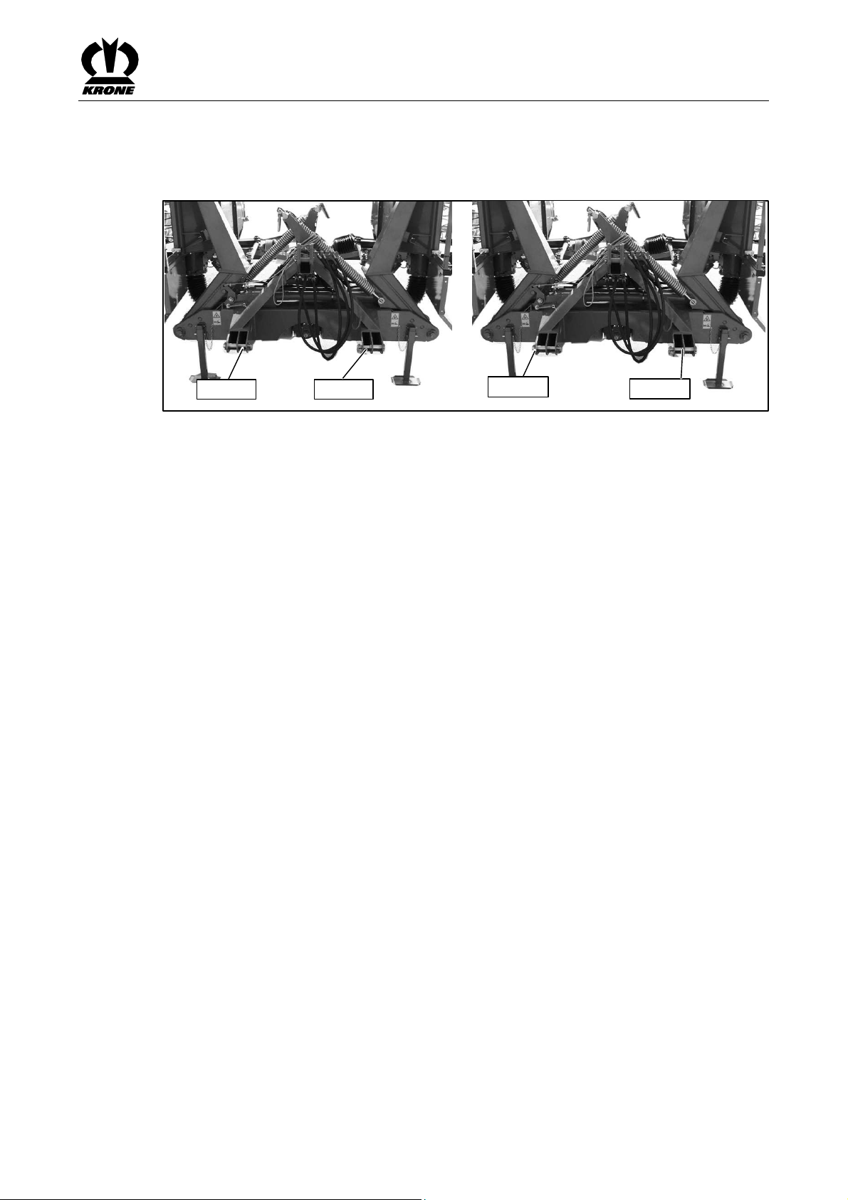
Pos:13.21/ BA/Sicherheit/Gefahrenhinweise/Mäh werke/UnbeabsichtigtesA bkuppelnangehängte @10\ mod_1221811842601_78.doc @137877
Danger! - Inadvertent uncoupling of the machine during road travel or work.
Effect: Danger to life, serious injuries or serious damage to the machine.
• Use extreme caution when attaching or detaching devices to or from the tractor! The
accident prevention regulations must be complied with absolutely.
• In order to prevent swivelling of the machine during transport or work, the lower
suspension arms on the tractor must be secured by limiting chains or bars. If the lower
suspension arms (1) are equipped with catch hooks, the following items must be taken
into consideration:
High forces develop in the lower suspension arm bolts (3) especially in the headland position.
For this reason, the catch hooks must be in a flawless condition. Additionally, the catch hooks
must be secured in the provided locking hole (4) against unwanted opening after the machine
has been connected to the tractor.
Pos:13.22/ BA/Erstinbetriebnahme/EasyCut/Anku ppelnBild EC7540/9140 @11\mod_ 1223293439581_78.doc @145432
Commissioning
Pos:13.23/ BA/Erstinbetriebnahme/EasyCut/Anku ppelnText EC280/320 (280/320CV-Q)@ 9\mod_12205374213 83_78.doc@ 126948
Pos:13.24/ BA/-----Seitenumbruch------ @0\mod_119617 5311226_0.doc@ 4165
Fig. 8
• Attach the machine onto the lower suspension arm (1) of the tractor.
• Hook the top link (2) into the upper hole of the 3-point support.
31

Commissioning
Pos:13.25/ BA/Erstinbetriebnahme/EasyCut/L ängenanpassungBild EC7540/9140 @11\mod_12233803 84360_78.doc@ 145751
EC-0-108
Pos:13.26/ BA/Erstinbetriebnahme/EasyCut/L ängenanpassung_ohnePf ahlsicherung@ 10\mod_1221813873039_78.d oc@ 138060
Pos:13.27/ BA/Sicherheit/Gelenkwelle/Achtung Schwenkbereich/Freira umüberprüfen @9\mod_122053 6308930_78.doc@ 126898
Pos:13.28/ BA/Erstinbetriebnahme/Gelenkwelle/Tr aktorwechselGelenkw ellenlängebeachten @6\mod _1214996938591_78.doc@ 97742
Pos:14/BA/-- ---Seitenumbruch------ @0\mod_119617531 1226_0.doc@ 4165
Fig. 9
The length of the PTO shaft (1) must be adjusted.
• Disassemble the PTO shaft.
• Install each half (1) and (2) on the tractor and machine side respectively.
• Check the special section tubes and guard tubes.
• Shorten special section tubes and guard tubes to an extent that the PTO shaft can move
freely in the shortest operating position.
• For additional operating instructions refer to the operating instructions of the PTO shaft
manufacturer.
Caution! - Swivel range of the PTO shaft
Effect: Damage to the tractor or the machine
• Check the swivel range and clearance of the PTO shaft!
Caution! - Changing the tractor
Effect: Damage to the machine
When using the machine for the first time and whenever changing the tractor Check PTO shaft
for the correct length. If the length of the PTO shaft does not match the tractor, always observe
the chapter entitled "Adjusting the length of the PTO shaft".
32

Pos:15.1/Üb erschriften/Überschriften 1/F-J/Inbetriebnahme @0\mod_1196327 075811_78.doc@ 6375
6 Start-up
Pos:15.2/Üb erschriften/Überschriften 2/A-E/Anbauan denTrakt or@0\m od_1199717845194_78.doc @34039
6.1 Mounting onto the Tractor
Pos:15.3/B A/Sicherheit/Gefahrenhinweise/Mähw erke/Unbeabsichtigtes Abkuppelnangebaute @9\mod _1220537942289_78.doc @126969
Danger! - Inadvertent uncoupling of the machine during road travel or work.
Effect: Danger to life, serious injuries or serious damage to the machine.
• Use extreme caution when attaching or detaching devices to or from the tractor! The
accident prevention regulations must be complied with absolutely.
• The lower suspension arms on the tractor must be fixed in position
with the retaining chains or bars to prevent the machine from swivelling out during
transport or work. If the lower suspension arms (1) are equipped with catch hooks, the
following items must be taken into consideration:
Especially in the headland position, high forces develop in the lower suspension arm bolts (3)
that act upwards in the left-hand hook.
For this reason, the catch hooks must be in a flawless condition.
Additionally, the catch hooks must be secured in the provided locking hole (4) against
unwanted opening after the machine has been connected to the tractor.
Pos:15.4/B A/Sicherheit/Gefahrenhinweise/Mähw erke/AchslastenBeein trächtigungder Lenkfähigkeit@ 9\mod_12208665559 85_78.doc@ 128119
Warning - Impairment of the steerability of the tractor.
Start-up
Pos:15.5/B A/Erstinbetriebnahme/EasyCut/An kuppelnBild EC7540/9140 @11\mod_1 223293439581_78.doc@ 145432
Pos:15.6/B A/Erstinbetriebnahme/EasyCut/An kuppelnTextEC 280/320 (280/320CV-Q)@ 9\mod_122053742138 3_78.doc@ 126948
Pos:15.7/B A/-----Seitenumbruch------ @0\mod_1196175 311226_0.doc@ 4165
Effect: Damage to the tractor or the machine.
The attachment of implements at the front and rear must not cause exceedance of the max.
permissible weight, of the permissible axle loads and of the carrying capacities of the tractor
tyres. Even with a fitted rear-mounted accessory unit, the front axle must always be loaded with
a minimum 20% service weight of the tractor.
Make sure that these prerequisites are met prior to driving.
Fig. 10
• Attach the machine onto the lower suspension arm (1) of the tractor.
• Hook the top link (2) into the upper hole of the 3-point support.
33

Start-up
Pos:15.8/Üb erschriften/Überschriften 2/F-J/Hydraulik@ 0\mod_119977603495 0_78.doc@ 34205
6.2 Hydraulics
Pos:15.9/Üb erschriften/Überschriften 3/P-T/SpezielleSic herheitshinweise@ 0\mod_1197301069931_7 8.doc@1 7662
6.2.1 Special Safety Instructions
Pos:15.10/ BA/Sicherheit/Hydraulik/Gefahr Anschlussd erHydraulikleitungen @0\mo d_1199776548685_78.doc @34225
Warning ! - Connection of the hydraulic line
Effect: severe injuries due to penetration of hydraulic oil under the skin.
• When connecting the hydraulic hoses to the hydraulic system of the tractor, the system
must be relieved of the pressure on either side.
• Due to the risk of injury when searching for leaks, always use suitable tools and wear
protective goggles.
• Seek medical help immediately should injuries occur! Danger of infection.
• Depressurise prior to uncoupling the hydraulic hoses and working on the hydraulic
system!
• Check the hydraulic hose lines at regular intervals and replace them if damaged or worn!
The replacement hoses must fulfil the technical requirements set by the equipment
manufacturer.
Pos:15.11/Ü berschriften/Überschriften 3/A-E/Anschlussd erHydraulikleitunge n@0\mo d_1199777037794_78.doc @34244
6.2.2 Connecting the hydraulic lines
Pos:15.12/ BA/Sicherheit/Hydraulik/Vertauschen derH ydraulikkleitungen@ 9\mod_1220871857985_78.d oc@ 128182
Warning - If the hydraulic hoses are interchanged when connecting them to the
hydraulic system of the tractor, the functions will be interchanged as well.
Effect: Injuries, serious damage to the machine
• Identify the hydraulic connections.
• Always ensure correct connection between the machine and the tractor.
• When engaging the hydraulic hose, the hydraulic control unit must be in float position or
in "lowering" position.
Pos:15.13/ BA/Sicherheit/Hydraulik/Verschmutzu ngderH ydraulikanlage@ 2\mod_1202393336803_7 8.doc@5 9155
Caution! - Soiling of the hydraulic system
Effect: Damages to the machine
• When connecting the quick couplings, ensure that these are clean and dry.
• Note chafing areas or points of contact.
Pos:15.14/ BA/Sicherheit/Betätigungsseil/Betätig ungsseilverlegen @8\mod_12 19298996457_78.doc@ 111447
Danger! - Unintended actions triggered.
Effect: Danger to life, injuries or damage to the machine.
• The actuating rope must be routed in such a way that no movements are unintentionally
triggered in any transport or working positions.
• The actuating rope must not come into contact with the tractor tyres
• Note chafing areas or points of contact.
Pos:15.15/ BA/-----Seitenumbruch------ @0\mod_119617 5311226_0.doc@ 4165
34

Pos:15.16/ BA/Inbetriebnahme/Schwader/Hinw eisHydraulikaufkleber beachten@ 9\mod_12199975317 85_78.doc@ 124879
Pos:15.17/ BA/Inbetriebnahme/EasyCut/Hydrauli k/Hydraulikanschluss BildEC 9140/75 40@17\ mod_1236087118303_78.doc @201128
Start-up
Note
Connect the hydraulic lines correctly
• The hydraulic hoses are identified by coloured hose clips.
• When connecting the hydraulic lines, observe the sticker for the tractor hydraulics (see
the "Safety" chapter: "Position of the general information labels on the machine").
Pos:15.18/ BA/Inbetriebnahme/EasyCut/Hydrauli k/Steuergerät2xEW @11\mod _1223382062798_78.doc@ 145797
Pos:15.19/ BA/Inbetriebnahme/EasyCut/Hydrauli k/Verweisauf Kippschalteran derBedie nungEC 7540/9140@ 11\mod_1223382973595_78.d oc@14 5841
Figure 11
Two single-action control units are required on the tractor to operate the machine.
The following functions of control devices depend on the setting of the flip switches on the
Pos:15.20/ BA/Inbetriebnahme/EasyCut/Hydrauli k/AnschlussHydrauli kleitungEC7540/9140 mitQFB @11\mo d_1223382307470_78.doc @145819
control unit (see chapter on Operation "Function of the switches on the control unit".)
Single-action control unit (1) (red 1):
• raises or lowers both mowing units from the transport position to the headland position
• raises or lowers the left mowing unit from the working position to the headland position or
With the cross conveyor only:
• raises or lowers the left cross conveyor
Single-action control unit (2) (red 2):
• raises or lowers the right mowing unit from the working position to the headland position
With cross conveyor option only:
Pos:15.21/ BA/-----Seitenumbruch------ @0\mod_119617 5311226_0.doc@ 4165
• raises or lowers the right cross conveyor
and vice-versa.
vice-versa.
or vice-versa.
35

Start-up
Pos:15.22/Ü berschriften/Überschriften 2/A-E/Anschlußd erelektrischen Bedienung@ 2\mod_1202396974288_ 78.doc@ 59195
6.3 Connecting the electrical controls
Pos:15.23/ BA/Inbetriebnahme/EasyCut/Anschl ussele ktrischeBedienung EC2800/3200/ 3210/4013/7540/9140@ 10\mod_12220701 41960_78.doc@ 138652
The connection of the electrical controls is performed by means of the power supply cable
• Insert the plug of the power supply cable into the tractor's continuous power socket.
• Position the cable so that it will not come in contact with the wheels.
Pos:15.24/ BA/Sicherheit/elektrische Bedienung/Achtung Anschlussder Bedienung@ 11\mod_122242102949 9_78.doc@ 141746
Caution! - Connecting the electrical controls
Effect: Damage to the control unit
Before inserting the plugs, make certain the plugs and sockets are clean and dry. Dirt and
moisture may result in short circuits!
Pos:15.25/ BA/-----Seitenumbruch------ @0\mod_119617 5311226_0.doc@ 4165
36

Pos:15.26/Ü berschriften/Überschriften 2/A-E/Beleuchtung@ 0\mod_1195658 399935_78.doc@ 1881
6.4 Lighting
Pos:15.27/ BA/Sicherheit/Fahren undTransport/Beleuch tung/Beleuchtungsanlage alleMaschinen @7\mod_121 5519058839_78.doc@ 103206
Danger! - Lighting system
Effect: Danger to life, serious injuries or serious damage to the machine.
• Before transporting on public roads, always connect the lighting system and perform a
function check.
• Keep the lighting system clean. Soiled lights and spotlights impair road safety.
• Replace defective light bulbs or broken spotlights.
• When transporting on public highways, the machine must be in the transport position.
Pos:15.28/Ü berschriften/Überschriften 2/A-E/AnschlussB eleuchtung@ 33\mod_1254385308979_78. doc@3 19105
6.5 Lighting connection
Pos:15.29/ BA/Inbetriebnahme/EasyCut/Beleucht ung/AnschlussBeleucht ungT1EC 7540/9140 @11\mod_1 223384700516_78.doc@ 145926
To comply with the Road Traffic Licensing Regulations, the machine is equipped as follows by
default:
• 3-chamber rear lamps (3) (direction indicator: reversing light and brake light)
• with red reflectors on the rear (4)
Pos:15.30/ BA/Inbetriebnahme/EasyCut/Beleucht ung/AnschlussBeleucht ungT2Bil dEC7 540/9140@ 11\mod_1223384996095_78. doc@145 948
• with lateral yellow reflectors on the rear (5)
Start-up
Pos:15.31/ BA/Inbetriebnahme/EasyCut/Beleucht ung/AnschlussBeleucht ungT3EC 2800/3200 3210/4013/7540/9140 @11\mod_12 22421634749_78.doc@ 141790
Fig. 12
The lighting system is connected via the 7-pin connection cable (2).
To do this:
• Insert the 7-pin connection cable plug (2) into the appropriate socket (1) of the machine.
• Insert the 7-pin connection cable plug (2) into the appropriate socket of the tractor.
• Position the cable so that it will not come in contact with the wheels.
Pos:15.32/ BA/Inbetriebnahme/Schwader/Hinw eisSauberkeit derStecker undSteckdose n@2\ mod_1202399563131_78.doc @59273
Note
Before inserting the plugs, make certain the plugs and sockets are clean and dry. Dirt and
moisture may result in short circuits!
Pos:15.33/ BA/-----Seitenumbruch------ @0\mod_119617 5311226_0.doc@ 4165
2
3
5
4
EC810022
37

Start-up
Pos:15.34/Ü berschriften/Überschriften 2/F-J/Gelenkwelle @0\mod_1199781879 794_78.doc@ 34542
6.6 PTO shaft
Pos:15.35/Ü berschriften/Überschriften 3/P-T/Spezielle Sicherheitshinweise@ 0\mod_1197301069931_ 78.doc@ 17662
6.6.1 Special Safety Instructions
Pos:15.36/ BA/Sicherheit/Gelenkwelle/Sich drehendeGel enkwelle_2@ 0\mod_1199781692950_78.doc @3452 3
Danger! - Rotating PTO shaft
Effect: Danger to life or serious injuries
• Install or detach the PTO shaft only with the engine switched off and the ignition key
removed.
• Secure the tractor against rolling.
• Make sure that the PTO shaft is coupled properly (the lock of the PTO shaft must have
snapped in).
• Make sure that the protective devices are attached properly.
• Never use a PTO shaft, the protective devices of which have not been attached.
• Replace damaged protective devices immediately
• Attach the safety chain of the PTO shaft so that the guard tube does not rotate
simultaneously with the PTO shaft.
Pos:15.37/ BA/Sicherheit/Gelenkwelle/Falsche Zapfwellendrehzahl 1000U/mi n@10\m od_1221819449336_78.doc @138326
Danger! - Incorrect PTO speed
Effect: Danger to life, serious injuries or damage to the machine.
• This machine may only be driven with a max. PTO speed of 1000 rpm.
• Before switching on the PTO, make sure that you have selected the correct PTO speed.
Pos:15.38/ BA/Sicherheit/Gelenkwelle/Achtung Schwenkbereich/Freira umüberprüfen @9\mod_122053 6308930_78.doc@ 126898
Caution! - Swivel range of the PTO shaft
Effect: Damage to the tractor or the machine
• Check the swivel range and clearance of the PTO shaft!
Pos:15.39/ BA/-----Seitenumbruch------ @0\mod_119617 5311226_0.doc@ 4165
38

Pos:15.40/Ü berschriften/Überschriften 3/F-J/Gelenkwelle montieren@ 11\mod_1223358863095_78.doc @14 5571@3 @1
6.6.2 Install the PTO shaft
Pos:15.41/ BA/Inbetriebnahme/EasyCut/Anbau Gelenkwelle/Anbau Gelenkwelle EC7540/9140 Bild@ 11\mod_1223383268376_78.doc @145 862@ @1
Start-up
Pos:15.42/ BA/Inbetriebnahme/EasyCut/Anbau Gelenkwelle/Anbau Gelenkwelle gezogene/angehängte EasyCuts @9\mod_12208748 76438_78.doc@ 128292@ @ 1
Fig. 13
• Slide the PTO shaft (1) onto the PTO end of the tractor and secure it.
Pos:15.43/Ü berschriften/Überschriften 2/U-Z/Zwischengelenkwelle @3\mod_ 1204702241039_78.doc @71481 @2@ 1
• Secure the PTO shaft guard against turning with the retaining chain (2).
6.7 Intermediate PTO shaft
Pos:15.44/ BA/Inbetriebnahme/EasyCut/Anbau Gelenkwelle/Zwischengel enkwelle/Zwischengelenkwellen BildEC7540/9 140@ 129\mod_1346747746275_78.doc @1154079 @ @1
Pos:15.45/ BA/Inbetriebnahme/EasyCut/Anbau Gelenkwelle/Zwischengel enkwelle/Zwischengelenkwelle TextEC7540/ 9140@1 29\mod_1346747092747_78.doc @1153895 @ @1
Fig. 14
The intermediate PTO shafts (1) for the tedder drives are coupled to the gearbox of the
headstock via the friction clutches (2). The retaining chains (3) must be fastenend on the
respective guard cups (4).
Pos:15.46/ BA/Inbetriebnahme/EasyCut/Hinweis Reibkupplung @11\mod_12233 58975938_78.doc@ 145593@ @ 1
Note - Friction Clutch
Effect: Conserve functionality and increased service life
• The friction clutch (2) must be vented prior to commissioning and once a year prior to
harvesting. (See section Before new season "Friction clutch")
Pos:15.47/ BA/---------------Seitenumbruch---- ------------@ 0\mod_1196175311226_0.doc @4165 @ @1
39

Start-up
Pos:15.48/Ü berschriften/Überschriften 2/A-E/Abstellstützei nTransportstellung schwenken @10\mod_1221637 347634_78.doc@ 135539
6.8 Swivelling parking support into transport position
Pos:15.49/ BA/Bedienung/Eas yCut/Abstellstütze/Abstellstütze eingeklapptBild EC7540/9140 @11\mod_12234 44129381_78.doc@ 146330
2
Pos:15.50/ BA/Bedienung/Eas yCut/Abstellstütze/Abstellstützen inTransportstell ungschwenken @12\mod_1224 048566368_78.doc@ 149887
Pos:16/BA/-- ---Seitenumbruch------ @0\mod_119617531 1226_0.doc@ 4165
3
1
22
1
4
EC800009
Fig. 15
After the machine is attached, swivel the parking supports into transport position.
• Use the three-point hydraulic system to raise the machine somewhat.
• Swivel the parking supports (1, 2) into transport position and lock it in place with the bolts
(3, 4).
40

Pos:17.1/Üb erschriften/Überschriften 1/F-J/Fahrenund Transport@ 0\mod_119633004 9217_78.doc@ 6553
7 Driving and Transport
Pos:17.2/B A/Sicherheit/Fahrenu ndTransport/Transport /Straße nfahrtEC 280/320@ 9\mod_1220877391360_78.doc @1283 56
Danger! - Transport / road travel
Effect: Danger to life, serious injuries or serious damage to the machine.
• When driving on public roads, the provisions of the Road Traffic Licensing Regulations
must be adhered to (lighting, identification, axle loads, permissible measurement of
additional housing component, etc.)!
• When being transported on public roads, the mowing unit must be lifted.
Pos:17.3/B A/Sicherheit/Fahrenu ndTransport/Absperrha hn/Transport/ StraßenfahrtAbs perrhahnschließen @11\mod_ 1223386244345_78.doc @145994
Danger! - Transport / road travel
Effect: Danger to life, serious injuries or serious damage to the machine.
• In transport position, always close the hydraulic shut-off valve.
Pos:17.4/B A/Sicherheit/Fahrenu ndTransport/Gefahr Straßenfahrt mitBedieneinheit /QFB EC7540/91 40@11\ mod_1223440953788_78.doc @146147
Danger! - Unexpected actions on the machine.
Effect: Danger to life, serious injuries or serious damage to the machine.
• Depending on the position of the control devices, switching the electrical control unit
could cause functions to be triggered. Caution is therefore advised during operation if
there is anyone in the area of the machine.
• To prevent functions from being triggered accidentally, it is essential to turn off the
control unit when the machine is being transported.
• To move the entire machine to the transport position, the cross conveyor belts must
previously have been let down so they cannot collide with each other in the transport
position.
Pos:17.5/Üb erschriften/Überschriften 2/U-Z/VonArbeitsst ellungin Transportstellung@ 2\mod_1202466246542 _78.doc@ 59681
7.1 Switching from working position to transport position
Pos:17.6/B A/Sicherheit/Fahrenu ndTransport/Hochsch wenkendes Mähwerksin Transportstellung @9\mod_12208772 53845_78.doc@ 128335
Danger! - Swinging the mowing unit up into transport position
Effect: Danger to life or serious injuries.
• Before swivelling the mowing unit up into transport position, turn off the PTO.
• The mowing unit may be lifted only once it has come to a complete standstill.
• Folding up of the mower as well as approaching it only once the machine has come to a
complete standstill!
• The mowing discs can continue to rotate after the drive has been switched off.
• In transport position, it is essential to observe the larger height of the mowing unit.
• Riding on the mowing unit is not permitted.
Pos:17.7/B A/-----Seitenumbruch------ @0\mod_1196175 311226_0.doc@ 4165
Driving and Transport
41

Driving and Transport
Pos:17.8/B A/Fahrenund Transport/EasyCut/Fahren-Tr ansportBild EC7540/9140 @11\mod_ 1223386858860_78.doc @146016
Pos:17.9/B A/Fahrenund Transport/EasyCut/Fahren/Tra nsportText mitA bsperrhahnEC 7540/9140@ 11\mod_122338693067 3_78.doc@ 146038
Fig. 16
For transport/road travel, the disc mower units must be folded upward.
To do this:
• Switch off PTO drive.
• Swivel the parking supports into transport position and lock it into position with the bolts
• Move the flip switch (2) to the "Down" position (see chapter on operation "Function of
• Move the flip switch (3) to the "Middle" position (see chapter on operation "Function of
• Activate the single-action control device (1) (red 1) to raise the mowing units slowly from
• Move the flip switch (2) to the "Up" position (see chapter on operation "Function of
• Activate the single-action control device (red 1) to raise the mowing units from the
• Switch off the control unit.
• Close the shut-off valve (1).
• Raise the right and left parking supports for transport/road travel and lock them in place
• Swivel the parking back for the transport/road travel and lock it in place with the bolt (see
Pos:17.10/ BA/-----Seitenumbruch------ @0\mod_119617 5311226_0.doc@ 4165
2
1
3
4
EC800038
(see chapter on start-up entitled "Swivelling the parking support into transport position").
switches on the control unit").
switches on the control unit").
the working position to the headland position.
switches on the control unit").
headland position to the transport position.
with the bolt (see chapter on Operation "Parking support").
chapter on Operation "Parking Support").
42

Pos:17.11/Ü berschriften/Überschriften 3/P-T/Transportverriegelung prüfen@ 11\mod_1223388487798 _78.doc@ 146080
7.1.1 Checking the transport interlock
Pos:17.12/ BA/Sicherheit/Fahren undTransport/Transp ortverriegelung/Transport/Straßenfahrt Prüfend erTransportverriegelung EC7140/ 9540@ 11\mod_1223388250360_78.doc @146060
Danger! - Checking the Transport Interlock
Effect: Danger to life, injuries or damage to the machine.
Make certain after swivelling the mowing units up that the right and left locks are engaged.
Pos:17.13/ BA/Fahrenund Transport/EasyCut/Vergewiss ern,dass dieVerriegelungen eingerastet sindBild @11\mod_12233894 21876_78.doc@ 146125
Driving and Transport
Pos:17.14/ BA/Fahrenund Transport/EasyCut/Vergewiss ern,dass dieVerriegelungen eingerastet sind.@ 11\mod_1223388604657_78.doc @146104
Fig. 17
By folding up the mowing units attached to the rear, the mowing units are automatically locked
against inadvertent lowering through a mechanical interlock (1).
Make certain after swivelling the mowing units up that the right and left locks (1) are engaged.
Pos:18/BA/-- ---Seitenumbruch------ @0\mod_119617531 1226_0.doc@ 4165
43

Operation
Pos:19.1/Üb erschriften/Überschriften 1/A-E/Bedienung@ 0\mod_119978950540 3_78.doc@ 34825
8 Operation
Pos:19.2/B A/Sicherheit/Fahrenu ndTransport/Gefahr Straßenfahrt mitBedieneinheit /QFB EC7540/91 40@11\ mod_1223440953788_78.doc @146147
Danger! - Unexpected actions on the machine.
Effect: Danger to life, serious injuries or serious damage to the machine.
• Depending on the position of the control devices, switching the electrical control unit
could cause functions to be triggered. Caution is therefore advised during operation if
there is anyone in the area of the machine.
• To prevent functions from being triggered accidentally, it is essential to turn off the
control unit when the machine is being transported.
• To move the entire machine to the transport position, the cross conveyor belts must
previously have been let down so they cannot collide with each other in the transport
position.
Pos:19.3/B A/-----Seitenumbruch------ @0\mod_1196175 311226_0.doc@ 4165
44

Pos:19.4/Üb erschriften/Überschriften 2/F-J/Funktionder Schalter Bedieneinheit@ 35\mod_1257922602863_78.d oc@ 333387
With "cross conveyor" option
8.1 Function of the switches on the control unit
Pos:19.5/B A/Bedienung/EasyCut /Funktionder SchalterBedien einheitmit QFBEC7540/9140 @11\mo d_1223446903803_78.doc @146462
Operation
2
1
3
4
EC800038
Fig. 18:
The control unit can be used to select various functions of the machine. The actual functions are
performed by the control units.
The following table explains the function of the individual switches.
Item Designation Function
1 Pilot lamp (red) Lit when the control unit is turned on.
2 Flip switch Middle: Control unit off
Top: Control unit (1) (red 1): raises or lowers both mowing units
from the transport position to the headland position and vice-
versa.
Bottom: lower rocker switch (3) is activated.
Left: Control unit (1) (red 1): raises or lowers the left mowing unit
from the working position to the headland position or vice-
versa Control unit (2) (red 2): raises or lowers the right
Rocker switch
(only active if
3
rocker switch 2
is pointing
down)
4 Rotary
potentiometer
Middle: Control unit (1) (red 1): raises or lowers both mowing units
right: With "cross conveyor" option
The rotary potentiometer can be used to adjust the speed of the cross
conveyors.
clockwise = faster
anticlockwise = slower
mowing unit from the working position to the headland
position or vice-versa
from the working position to the headland position or vice-
versa
Control unit (1) (red 1): raises and lowers the left cross
conveyor. Control unit (2) (red 2): raises and lowers the right
cross conveyor.
Pos:19.6/B A/-----Seitenumbruch------ @0\mod_1196175 311226_0.doc@ 4165
45

Operation
Pos:19.7/Üb erschriften/Überschriften 2/U-Z/VonTransport inAr beitsstellung@ 2\mod_1202466185276_78.doc @596 62
8.2 From transport into working position
Pos:19.8/B A/Sicherheit/Gefahrenhinweise/Mähw erke/Absenkendes Mähwerksi nArbeitsstellung EC280/320 @9\mod _1220879244798_78.doc @128439
Danger! - Lowering the mowing unit into the working position
Effect: Danger to life, injuries or damage to the machine.
• Lower the mowing unit only when you are absolutely sure that neither persons, animals
nor objects are in the swivel range of the mowing unit.
• Switch on the PTO only when the mowing unit is resting on the ground.
Pos:19.9/B A/Bedienung/EasyCut /VonTransport inArbeitsstellung BildEC 7540/9140@ 11\mod_1223442776975_78.d oc@ 146308
Pos:19.10/ BA/Bedienung/Eas yCut/Transportin Arbeitsstellung mitAbsperrhahn TextEC 7540/9140@ 11\mod_1223442362 085_78.doc@ 146286
Fig. 19
To do this:
• Open the shut-off valve (1).
• Move the flip switch (2) to the "Up" position (see chapter on operation "Function of
• To lower the mowing unit, pull up the lock (1) from the tractor using the actuating rope (2).
• Activate the single-action control device (1) (red 1) to lower the mowing units slowly from
• Move the flip switch (2) to the "Down" position (see chapter on operation "Function of
• Move the flip switch (3) to the "Middle" position (see chapter on operation "Function of
• Activate the single-action control device (red 1) to lower the mowing units from the
Pos:19.11/ BA/-----Seitenumbruch------ @0\mod_119617 5311226_0.doc@ 4165
2
1
3
4
EC800038
switches on the control unit").
the transport position to the headland position.
switches on the control unit").
switches on the control unit").
headland position to the working position.
46

Pos:19.12/Ü berschriften/Überschriften 2/U-Z/Vordem Mäheinsatz @3\mod_1204788 384465_78.doc@ 73168
8.3 Before mowing
Pos:19.13/ BA/Sicherheit/Gefahrenhinweise/Mäh werke/Gefahr- Arbeitseinsatz/ Mähen@ 73\mod_1307695972 255_78.doc@ 654926
DANGER! - Using the machine for work
Effect: Danger to life, injuries or damage to the machine.
• The glide skids must rest on the ground before start-up and during work
• Maintain an adequate safety distance from the cutting tools during operation
• There is danger of foreign objects being forcibly ejected even when the machine is
operated properly. Persons must therefore be directed out of the danger zone of the
machine.
• Special care should be taken when working near roads and buildings)
Pos:19.14/ BA/Sicherheit/Gefahrenhinweise/Mäh werke/UnerwarteteBew egungder Schneidwerkzeuge bzw.desM ähwerkes.Fortschl eudernvon Steinenwährend des@ 3\mod_1204788756340_78.d oc@ 73207
Danger! - Unexpected movement of the cutting tools or the mowing unit. Stones are
hurled up during operation
Effect: Danger to life, injuries or damage to the machine.
• Do not carry out work on the disc mower until the PTO has been switched off, the engine
has been turned off and the ignition key has been removed! Secure the tractor against
accidental start-up and against rolling!
• Support the lifted cutter bar! Never step under suspended loads!
• Before using the machine, always check the protective devices for damage. Replace
damaged protective devices immediately.
• Safe operation is only guaranteed if the blades have been fitted according to the
instructions!
• Before starting operation, always check the mowing unit for damaged, missing or worn
blades, retaining bolts, leaf springs and cutting discs/blade drum; replace any parts that
are damaged, missing or worn!
• Always replace missing and damaged blades in sets to prevent unbalanced rotation!
• Never install unevenly worn blades on a drum/disc!
• Whenever a blade is changed, also inspect the fasteners and, if required, replace them!
• Move the protective devices into their protective positions.
Operation
Pos:19.15/ BA/Bedienung/Eas yCut/BeimMähen Steuerventilsc hwimmstellung/senken@ 9\mod_12208814123 91_78.doc@ 128661
Pos:19.16/ BA/-----Seitenumbruch------ @0\mod_119617 5311226_0.doc@ 4165
Note! - While mowing
Effect: Proper use of the machine
• Leave control unit(s) in the "Lower" or "Float position" position for work.
47

Operation
Pos:19.17/Ü berschriften/Überschriften 3/P-T/Schutzeinrichtung herunterklappen@ 9\mod_122088107 9079_78.doc@ 128594
8.3.1 Folding down the Safety Device
Pos:19.18/ BA/Sicherheit/Gefahrenhinweise/Mäh werke/Fortschleudernvo nSteinen (2011-10-1107:44:0 8)@3\ mod_1204709370914_78.doc @71873
Danger! - Stones are hurled up during operation
Effect: Danger to life or serious injuries.
• Check the guard cloths regularly. Worn or damaged guard cloths must be replaced!
• The protective equipment on the mowing unit, e.g. cloths and hoods, protects against
flying stones and similar objects, and prevents access to dangerous parts. For this
reason you must always move them to their protective position before starting work.
Pos:19.19/ BA/Bedienung/Eas yCut/Schutze/Schutzeinrichtung herunterklappenBil dEC2 80/320CV-Q @10\mod_1221 543535479_78.doc@ 134305
1
Pos:19.20/ BA/Bedienung/Eas yCut/Schutze/Schutzeinrichtung herunterklappenTe xtEC 2800/3200@ 10\mod_1222153147826_78.d oc@13 8945
Figure 20
Fold down the protective devices (1) (guard cloths) on the left and right side before operation.
Pos:19.21/ BA/-----Seitenumbruch------ @0\mod_119617 5311226_0.doc@ 4165
EC-113-1
48

Pos:19.22/Ü berschriften/Überschriften 2/A-E/Abstellstützei nTransportstellung schwenken @10\mod_1221637 347634_78.doc@ 135539
8.4 Swivelling parking support into transport position
Pos:19.23/ BA/Bedienung/Eas yCut/Abstellstütze/Achtung Abstellstütze eingeklapptEC 280/320CV- Q@1 0\mod_1221637532743_78.doc @135563
Caution! - Parking support(s) not swivelled into transport position before road/transport
travel and for work!
Effect: Damage to the machine
• Make certain before road/transport travel and for work that the parking support(s) is/are
raised or folded in and secured in place with a bolt!
Pos:19.24/ BA/Bedienung/Eas yCut/Abstellstütze/Abstellstütze eingeklapptBild EC7540/9140 @11\mod_12234 44129381_78.doc@ 146330
2
Operation
Pos:19.25/ BA/Bedienung/Eas yCut/Abstellstütze/Abstellstützen einklappenEC 7540/9140 @11\mod_122344 4229897_78.doc@ 146352
Pos:19.26/ BA/-----Seitenumbruch------ @0\mod_119617 5311226_0.doc@ 4165
3
1
22
1
4
EC800009
Fig. 21
The machine is equipped with three parking supports (1+2).
• The parking supports (2) on the right-hand and left-hand sides in working position of the
disc mower must be lifted and locked in position with the bolt (3).
• Swivel the parking support (1) backward and lock it in position with the bolt (4).
49

Operation
Pos:19.27/Ü berschriften/Überschriften 3/P-T/SeitlicheLe nkereinstellen @9\mod_1220 882767235_78.doc@ 128767
8.4.1 Adjusting the lateral suspension arm
Pos:19.28/ BA/Sicherheit/EasyCut/Einstellung derUnterle nkerhöheam Traktor@ 9\mod_1220882859813_78. doc@1 28789
Danger! - Height adjustment of the lower suspension arms on the tractor
Effect: Danger to life, injuries or damage to the machine.
• Switch off the PTO.
• Secure the tractor against rolling.
• Do not step into the space between the tractor and the machine.
Pos:19.29/ BA/Bedienung/Eas yCut/Höheneinstellung/Höheneinstellung beimM ähenüberdi eUnterlenker amTraktor BildEC 7540/9140@ 11\mod_1223444555710_78.doc @14637 4
Pos:19.30/ Abkürzungen/Abkürz ungensprachneutral/E asyCut/EasyCut9140 CV@ 11\mod_1223444731538_0.d oc@ 146416
Pos:19.31/ BA/Bedienung/Eas yCut/Höheneinstellung/Höheneinstellung 50mm beimMä henüber dieUnterlenker amTraktor @10\mod_ 1221543862838_78.doc @134372
Fig. 22
(EasyCut 9140 CV)
During mowing, the height of the 3-point support must be adjusted so that the lateral
suspension arms (1) in the front area (1) are a= about 50 mm higher than in the rear area (2).
The setting can be selected via the height adjustment of the lower suspension arms on the
Pos:19.32/ Abkürzungen/Abkürz ungensprachneutral/E asyCut/EasyCut7540/91 40@1 1\mod_1223453159866_0.doc @146591
Pos:19.33/ BA/Bedienung/Eas yCut/Höheneinstellung/Höheneinstellung 20mm beimMä henüber dieUnterlenker amTraktor. @9\mod _1220882038173_78.doc@ 128725
tractor.
(EasyCut 7540, EasyCut 9140)
During mowing, the height of the 3-point support must be adjusted so that the lateral
suspension arms (1) in the front area (1) are a = about 20 mm higher than in the rear area (2).
The setting can be selected via the height adjustment of the lower suspension arms on the
Pos:19.34/ Abkürzungen/Abkürz ungensprachneutral/E asyCut/EasyCut10000 Shift@ 41\mod_1271851241507 _0.doc@ 373499
Pos:19.35/ BA/Bedienung/Eas yCut/Höheneinstellung/Höheneinstellung 0mm beimM ähenüberdi eUnterlenker amTraktor. @41\mod _1271851318445_78.doc@ 373526
tractor.
(EasyCut 10000 Shift)
During mowing, the height of the headstock must be adjusted so that the lateral suspension
arms (1) in the front area (1) and the rear area (2) are at the same level (a= ca. 0 mm).
The adjustment is made through the height adjustment of the lower suspension arms on the
Pos:19.36/ BA/-----Seitenumbruch------ @0\mod_119617 5311226_0.doc@ 4165
tractor.
50

Pos:19.37/Ü berschriften/Überschriften 2/U-Z/Vorgewendestellung @0\mod_11 96414916041_78.doc@ 8116
8.5 Headland Position
Pos:19.38/ BA/Sicherheit/Vorgewendestellung/ VorgewendeMähwerke EC280/ 320CV-Q @10\mod_1221544 654385_78.doc@ 134415
Danger! - Lifting the mowing unit from the working position into headland position
Effect: Danger to life, injuries or damage to the machine.
• Lift the mowing unit into headland position only when you are absolutely sure that neither
persons, animals nor objects are in the swivel range of the mowing unit.
Pos:19.39/ BA/Sicherheit/Fahren undTransport/Gefahr Straßenfahrt mitBedieneinheit /QFB EC7540/9 140@11 \mod_1223440953788_78.doc @146147
Danger! - Unexpected actions on the machine.
Effect: Danger to life, serious injuries or serious damage to the machine.
• Depending on the position of the control devices, switching the electrical control unit
could cause functions to be triggered. Caution is therefore advised during operation if
there is anyone in the area of the machine.
• To prevent functions from being triggered accidentally, it is essential to turn off the
control unit when the machine is being transported.
• To move the entire machine to the transport position, the cross conveyor belts must
previously have been let down so they cannot collide with each other in the transport
position.
Pos:19.40/ BA/-----Seitenumbruch------ @0\mod_119617 5311226_0.doc@ 4165
Operation
51

Operation
Pos:19.41/ BA/Bedienung/Eas yCut/Vorgewendemit QFBEC 7540/9140@ 11\mod_12234456 44194_78.doc@ 146440
Pos:19.42/ BA/-----Seitenumbruch------ @0\mod_119617 5311226_0.doc@ 4165
2
1
3
4
EC800038
Fig. 23
All the functions that are available while driving in headland position are listed below.
Rocker switch (2) Rocker switch (3) Description
Control unit (1) (red 1): raises or lowers the left
mowing unit from the working position to the headland
position or vice-versa. Control unit (2) (red 2): raises or
Bottom
Left
Bottom Middle
Bottom
Right
lowers the right mowing unit from the working position
to the headland position or vice-versa.
Control unit (1) (red 1): raises or lowers both mowing
units from the working position to the headland
position or vice-versa
With "Cross conveyor" option control unit (1) (red
1): raises and lowers the left cross conveyor. Control
unit (2) (red 2): raises and lowers the right cross
conveyor. .
52

Pos:19.43/Ü berschriften/Überschriften 2/A-E/Abbauder Maschine @3\mod_120479238 7824_78.doc@ 73245
8.6 Detaching the machine
Pos:19.44/ BA/Sicherheit/EasyCut/Maschine abstellen_mitH ydraulikschlauch@ 9\mod_12208832084 23_78.doc@ 128830
Danger! - Unexpected movements of the machine
Effect: Danger to life, serious injuries
• No one is permitted inside the danger zone.
• Park the machine on a solid and even surface.
• You should not unhitch the machine until the engine has been switched off and the
ignition key has been removed.
• Secure the tractor against rolling.
• Use extreme caution when attaching implements to or detaching them from the tractor!
The accident prevention regulations must be complied with absolutely.
• When connecting the hydraulic hose to and disconnecting it from the hydraulic system of
the tractor, the tractor system as well as the machine system must be depressurised!
Move the appropriate control valves into the flow position.
• When detaching the machine, do not walk between the tractor and the machine!
Pos:19.45/ BA/Bedienung/Eas yCut/AbkoppelnBild EC7540/91 40@1 1\mod_1223450642553_78.doc @146505
Operation
Pos:19.46/ BA/Bedienung/Eas yCut/AbkoppelnEC 7540/9140@ 11\mod_1223450393 163_78.doc@ 146484
Pos:19.47/ BA/-----Seitenumbruch------ @0\mod_119617 5311226_0.doc@ 4165
Fig. 24
• Lower the three parking supports (1) and secure them in position with bolts (2).
• Use the tractor hydraulics to lower the machine to the ground.
• Remove the PTO shaft (3) from the tractor and place it on the storage surface (4).
• Disconnect the hydraulic hoses (5) from the tractor, fit the dust caps and hang them onto
the connection block.
• Disconnect the connection of the lighting cable (6) between the tractor and machine and
place it in the supports provided for that purpose.
• Disconnect the power supply plug (7) between the tractor and machine and place it in the
supports provided for that purpose.
• Remove the control unit (8) from the tractor and fasten it to the three point block.
• Remove the synthetic rope (9) from the tractor
• Relieve the top suspension arm and pull out the bolt on the device side / unhook the top
suspension arm.
• Pull out the lower suspension arm / release the catch hook.
53

Operation
Pos:19.48/Ü berschriften/Überschriften 2/A-E/Abstellen@ 0\mod_119980198062 2_78.doc@ 35320
8.7 Parking
Pos:19.49/ BA/Bedienung/Eas yCut/Abstellenmit hochgeklapptenM ähwerkenBild EC7540/91 40@1 1\mod_1223451145428_78.doc @146548
Pos:19.50/ BA/Bedienung/Eas yCut/Abstellenmit hochgeklapptenM ähwerkenEC 7540/9140@ 11\mod_122345092346 0_78.doc@ 146527
Pos:20/BA/-- ---Seitenumbruch------ @0\mod_119617531 1226_0.doc@ 4165
Fig. 25
Note - Parking with the mowing units folded up
Effect: Save space
For reasons of space, the machine can also be folded up for parking.
In this case, take special care to ensure that the two interlocks (1) (LH and RH) are hooked in
and that the mowing unit is parked only on especially solid ground such as concrete or asphalt.
54

Pos:21.1/Üb erschriften/Überschriften 1/A-E/Einstellungen@ 0\mod_119986878 3862_78.doc@ 36141
9 Settings
Pos:21.2/B A/Sicherheit/Gefahrenhinweise/Einstell arbeitenangebaute Maschinen@ 6\mod_121445587 5276_78.doc@ 94250
Danger! - Unexpected movements of the machine
Effect: Danger to life or serious injuries.
• Setting tasks must only be performed when the drive is switched off and the engine is at
a standstill!
• Switch off the engine
• Remove the ignition key.
• Secure the tractor against rolling.
Pos:21.3/Üb erschriften/Überschriften 2/A-E/Einstellender Schnitthöhe @0\mod_1196 660879619_78.doc@ 9191
9.1 Adjusting the cutting height
Pos:21.4/B A/Einstellungen/Mähwerke/Schnitthö he/SchnitthöheBild EC7540/ 9140@1 1\mod_1223453474460_78.doc @146635
Settings
Pos:21.5/B A/Einstellungen/Mähwerke/Schnitthö he/Schnitthöhegrößer_geri ngerEC280/320 @9\mod _1220960304209_78.doc@ 130271
Pos:21.6/B A/-----Seitenumbruch------ @0\mod_1196175 311226_0.doc@ 4165
Fig. 26
The cutting height is adjusted via the top link (1).
To do this:
• Swivel the parking support(s) down
• Lower the machine into working position and set it down on the parking support(s).
• Rotate the top suspension arm (1).
• Fold in the parking support(s).
Top suspension arm longer = bigger cutting height
Top suspension arm shorter = smaller cutting height
55

Settings
Pos:21.7/Üb erschriften/Überschriften 2/U-Z/Überschnitt einstellen@ 79\mod_131487 5045910_78.doc@ 698940
9.2 Adjust overcut
Pos:21.8/A bkürzungen/Abkürzu ngensprachneutral/Eas yCut/EasyCut9140 Shift@ 79\mod_1314876093621_ 0.doc@6 98993
Pos:21.9/B A/Einstellungen/Mähwerke/EasyC ut/Überschnitteinstellen Ausführung Shift@7 9\mod_1314875668288_78.doc @698968
(EasyCut 9140 Shift)
Fig. 27
The overcut to the front mowing unit can be reduced or enlarged with the outrigger arms (2)
(right and left side of machine). The machine is preset to position (I) in the factory.
Pos.I = basic setting (max. mowing width).
Pos.II = increase overcut 6 cm (on each side).
Pos.III = increase overcut 12 cm (on each side).
Procedure:
• Connect machine properly to the tractor.
• Lower the machine into working position.
• Lift machine slightly with the tractor's rear hydraulics.
• PTO shaft drive and tractor engine OFF.
• Activate tractor parking brake.
• Remove the ignition key.
Pos:21.10/ BA/-----Seitenumbruch------ @0\mod_119617 5311226_0.doc@ 4165
Warning! - Outrigger arm can slip out.
Danger of injury due to crushing.
Never pull the outrigger arm (2) out further than is required for the adjustment.
• Remove the bolt (1).
• Move the outrigger arm (2) to the required position only with suitable equipment (same
setting for right and left side of machine).
• Install the bolt (1) and secure in place.
56

Pos:21.11/Ü berschriften/Überschriften 2/U-Z/Überschnittei nstellen @79\mod_13148 75045910_78.doc@ 698940
9.3 Adjust overcut
Pos:21.12/ Abkürzungen/Abkürz ungensprachneutral/E asyCut/EasyCut10000 Shift@ 41\mod_1271851241507 _0.doc@ 373499
Pos:21.13/ BA/Einstellungen/Mähwerke/EasyCut/Üb erschnitteinstellen EC10 000Shift/ ECB 970@ 79\mod_1314876822108 _78.doc@ 699024
(EasyCut 10000 Shift)
Fig. 28
The overcut to the front mowing unit can be reduced or enlarged with the outrigger arms (2)
(right and left side of machine).
Pos.I = max. mowing width
Pos.II = increase overcut by 7,5 cm (on each side)
Pos.III = increase overcut by 15 cm (on each side)
Procedure:
• The machine must be properly connected to the tractor
• Bring machine into transport position with tractor rear hydraulics
• P.T.O. shaft drive and tractor engine OFF
• Activate tractor parking brake
• Remove the ignition key
Settings
EC-319-0
Pos:21.14/ BA/-----Seitenumbruch------ @0\mod_119617 5311226_0.doc@ 4165
WARNING! - Outrigger arm can slip out.
Risk of injury due to crushing.
The locking bolt (1) must be properly engaged in one of the positions (I, II or III).
• Pull the locking bolt (1) and bring into desired position (adjust right hand and left hand
side identically)
• Make certain that the locking bolt engages properly
57

Settings
Pos:21.15/Ü berschriften/Überschriften 2/A-E/Einstellung derSchutze @3\mod_12047 09091570_78.doc@ 71854
9.4 Adjusting the Guards
Pos:21.16/ Abkürzungen/Abkürz ungensprachneutral/E asyCut/EasyCut9140 CV@ 11\mod_1223444731538_0.d oc@ 146416
Pos:21.17/ BA/Sicherheit/Gefahrenhinweise/Mäh werke/Fortschleudernvo nSteinen (2011-10-1107:44:0 8)@3\ mod_1204709370914_78.doc @71873
Pos:21.18/ BA/Einstellungen/Mähwerke/Seitliche Schutze @3\mod_1204709512 195_78.doc@ 71892
9.4.1 Lateral guards
(EasyCut 9140 CV)
Danger! - Stones are hurled up during operation
Effect: Danger to life or serious injuries.
• Check the guard cloths regularly. Worn or damaged guard cloths must be replaced!
• The protective equipment on the mowing unit, e.g. cloths and hoods, protects against
flying stones and similar objects, and prevents access to dangerous parts. For this
reason you must always move them to their protective position before starting work.
Pos:21.19/ BA/-----Seitenumbruch------ @0\mod_119617 5311226_0.doc@ 4165
EC-0-027
Fig. 29
Lateral guards can be vertically adjusted. For this purpose, unscrew the screws (1) and (2).
Adjust the mounting bar (3) vertically. Tighten the screws.
58

Pos:21.20/ BA/Einstellungen/Mähwerke/Vorder eSchutze @11\mod_1223360 152282_78.doc@ 145615
9.4.2 Front guards
1
a
Settings
Pos:21.21/ BA/-----Seitenumbruch------ @0\mod_119617 5311226_0.doc@ 4165
AMT4-0-033
Figure. 30
Height adjustment determined by side guards.
Dimension a = 440 mm.
Predefined dimension "a" on the front guard (1) offers optimum protection against ejected
objects. (Guard is in parallel to the ground)
A screw driver is used to open the front guards. Use the screwdriver to push in the ratchet
mechanism.
EC-0-044
59

Settings
Pos:21.22/Ü berschriften/Überschriften 2/A-E/Einstellung derEntlastungsfedern @0\m od_1196666659447_78.doc@ 10133
9.5 Adjusting the Compensation Springs
Pos:21.23/ BA/Sicherheit/Gefahrenhinweise/Mäh werke/Einstellungan denEntlastu ngsfedernEC 7540/9140@ 36\mod_1258966594 894_78.doc@ 335742
DANGER! – Setting on the compensation springs
Effect: Danger to life or serious injuries
• The threaded spindles (2) of the compensation springs (1) must not be turned out further
than dimension X (see table).
• The nuts (3) must not be resting against the feeder rake (4) (make certain dimension a is
set to 3-5 mm).
Pos:21.24/ BA/Einstellungen/Mähwerke/EasyCut/B odendruck/Bodendruck allgemeinerText alleEC @0\mod_ 1196667271181_78.doc @10190
The ground pressure for the cutter bar is adjusted to local conditions by means of the
compensation springs. In order to protect the sward the load on the mowing spar must be
relieved so that it does not jump when mowing, yet does not leave any skid marks on the
Pos:21.25/ BA/Einstellungen/Mähwerke/EasyCut/B odendruck/BodendruckZ usatzEC 7540/9140@ 11\mod_1223453930835_7 8.doc@ 146679
Pos:21.26/ BA/Einstellungen/Mähwerke/EasyCut/E ntlastungsfeder(n)/Entlastungsfeder BildEc7 540/9140/10000@ 42\mod_1272541667536_78. doc@ 379120
ground.
The ground pressure can be adjusted through threaded spindles (2).
EasyCut 7540 80 mm
EasyCut 9140 Shift 80 mm
EasxCut 9410 CV 80 mm
EasyCut 9140 CV Collect 50 mm
EasyCut 10000 Shift 80 mm
Pos:21.27/ BA/Einstellungen/Mähwerke/EasyCut/E ntlastungsfeder(n)/Einstellung Entlastungsfeder HinweisEC 7540/9140@ 11\mod_1223454434944 _78.doc@ 146725
Fig. 31
Note - Setting on the compensation springs
Effect: equal ground pressure
• For the adjustment of the compensation springs, the disc mower must be moved into the
• Always make sure that the tensioning lengths of the springs on the right-hand and left-
Pos:21.28/ BA/-----Seitenumbruch------ @0\mod_119617 5311226_0.doc@ 4165
X
EasyCut 9140 CV / Collect
1
a
2
3
transport position.
hand sides are equal.
1
EasyCut 7540 /
EasyCut 9140 Shift
EasyCut 10000 Shift
4
1
2
2
a
3
4
EC810015_4
60

Pos:21.29/Ü berschriften/Überschriften 2/A-E/EinstellbareDr osseln@ 0\mod_1197295892260_78.doc @17199
9.6 Adjustable throttles
Pos:21.30/ BA/Einstellungen/Drossel/Drossel einstellenBil dEC7540/9140 @11\mod _1223455573210_78.doc@ 146834
Settings
Pos:21.31/ BA/Einstellungen/Drossel/Drossel einstellenallge meinEC7540/9140 @11\mo d_1223455063038_78.doc @146768
Fig. 32
You can use the adjustable throttles (1,2) to adjust the raising and lowering speed of the
hydraulic cylinders.
Pos:21.32/ BA/Einstellungen/Drossel/Drossel (1)Aushubge schwindigkeitArbeits- inVorge wendestellung@ 11\mod_1223455172960_ 78.doc@ 146790
Throttle (1)
Pos:21.33/ BA/Einstellungen/Drossel/Drossel (2)Aushubge schwindigkeitVorgewe nde-Transportstellung @11\ mod_1223455458835_78.doc @146812
Throttle (1) adjusts the lifting speed from working position to headland position.
Throttle (2)
Pos:21.34/ BA/-----Seitenumbruch------ @0\mod_119617 5311226_0.doc@ 4165
Throttle (2) adjusts the lifting speed from headland position to transport position.
61

Settings
Pos:21.35/Ü berschriften/Überschriften 2/A-E/Einstellung derZetterdrehzahl @0\mod_1 196668564463_78.doc@ 10266
9.7 Adjusting the Tedder Speed
Pos:21.36/ Abkürzungen/Abkürz ungensprachneutral/E asyCut/EasyCut9140 CV@ 11\mod_1223444731538_0.d oc@ 146416
Pos:21.37/ BA/Sicherheit/Gefahrenhinweise/Einst ellungenan derMaschine @0\mod_1 196668628056_78.doc@ 10285
Pos:21.38/ BA/Einstellungen/Mähwerke/Zetterdr ehzahl/Zetterdrehzahl BildEC280/320 CV-Q@ 10\mod_1221550487745_78. doc@134 924
(EasyCut 9140 CV)
Danger! - Settings on the machine
Effect: Danger to life, injuries or damage to the machine.
• Setting tasks must only be performed when the drive is switched off and the engine is at
a standstill! Remove the ignition key!
900
600
EC-2-119
Pos:21.39/ BA/Einstellungen/Mähwerke/Zetterdr ehzahl/Zetterdrehzahl einstellen600/900 @11\mod_122 3613453645_78.doc@ 148195
Pos:21.40/ BA/-----Seitenumbruch------ @0\mod_119617 5311226_0.doc@ 4165
Figure 33
Two tedder speeds can be set on the speed gearbox. This affects the conditioning effect and
the power consumption.
Minimum speed: 600 rpm.
Maximum speed: 900 rpm.
• Unscrew the wing screw (1) from the actuating lever (2).
• Rotate the actuating lever (2) 180°. In doing so, turn the mower drum (3) so that the
actuating lever can be rotated completely.
• Secure the actuating lever (2) with the wing screw (1).
62

Pos:21.41/Ü berschriften/Überschriften 2/A-E/Einstellend esAufbereitungsblechs @0\ mod_1196670615681_78.doc @10399
9.8 Adjusting the conditioner plate
Pos:21.42/ Abkürzungen/Abkürz ungensprachneutral/E asyCut/EasyCut9140 CV@ 11\mod_1223444731538_0.d oc@ 146416
Pos:21.43/ BA/Einstellungen/Mähwerke/Einstellung desA ufbereitungsblechesBild EC2 8/32CV 280/320CV @3\mod_120471 3442195_78.doc@ 72144
(EasyCut 9140 CV)
Fig. 34
Pos:21.44/ BA/Einstellungen/Mähwerke/Einstellung desA ufbereitungsblechesTe xtEasyCut @3\mod_120471 3282555_78.doc@ 72125
The conditioning of the mowed crop can be influenced by adjusting the conditioning plate
through the crank (1). The adjustment depends on the desired degree of conditioning of the
crop.
Settings
EC-032-0
Pos:21.45/ BA/-----Seitenumbruch------ @0\mod_119617 5311226_0.doc@ 4165
+: Degree of conditioning is increased
-: Degree of conditioning is decreased
Always check the tedder for damaged tines before the machine is used:
Straighten any bent tines.
Replace any broken tines.
63

Settings
Pos:21.46/Ü berschriften/Überschriften 2/A-E/Einstellung derPfahlsicherung @9\mod_12 20961168693_78.doc@ 130388
9.9 Setting of the pole protection mechanism
Pos:21.47/ BA/Sicherheit/EasyCut/Einstellung ander Pfahlsicherung @9\mod_12209609 55600_78.doc@ 130367
Caution! - Adjusting the pole protection mechanism
Effect: Damage to the machine
• If the setting value is changed, the trigger moment will also change. If the spring on the
pole protection mechanism is pretensioned more than prescribed by the manufacturer,
there is a risk of damaging the disc mower.
• The spring on the pole protection mechanism must be tensioned at least to the extent
that the pole protection mechanism does not respond in transport position even with
abrupt loads.
Pos:21.48/ BA/Einstellungen/Mähwerke/EasyCut/P fahlsicherung/Pfahlsicherung BildEC7540/9 140@ 11\mod_1223456077022_78.doc @146857
Pos:21.49/ BA/Einstellungen/Mähwerke/EasyCut/P fahlsicherung/Pfahlsicherung allgemein@ 9\mod_1220961293021_ 78.doc@ 130429
Fig. 35
In order to protect the disc mower against damages during driving over obstacles, it is equipped
with a so-called pole protection mechanism.
The optimal setting for the trigger moment takes place in the factory.
Pos:21.50/ BA/Einstellungen/Mähwerke/EasyCut/P fahlsicherung/Pfahlsicherung EC7540/9140/ 10000Shift Tabelle@ 41\mod_1271851995757_78.doc @3735 51
EASYCUT 7540 85 mm
EASYCUT 9140 85 mm
EASYCUT 9140 CV 85 mm
EASYCUT 10000 Shift 85 mm
Pos:21.51/ BA/Einstellungen/Mähwerke/EasyCut/P fahlsicherung/Pfahlsicherung nachdem AuslösenEC 7540/9140 @11\mod_12234 56599053_78.doc@ 146901
After the pole protection mechanism is triggered, the mowing unit swings back. The pole
Pos:21.52/ BA/-----Seitenumbruch------ @0\mod_119617 5311226_0.doc@ 4165
protection mechanism will catch again as soon as you move back.
Mower type Dimension x
64

Pos:21.53/Ü berschriften/Überschriften 2/A-E/EinstellenSc hwadbreite@ 0\mod_1196673972744_78.d oc@105 89
9.10 Adjusting the swath width
Pos:21.54/ Abkürzungen/Abkürz ungensprachneutral/E asyCut/EasyCut9140 CV@ 11\mod_1223444731538_0.d oc@ 146416
Pos:21.55/ BA/Einstellungen/Mähwerke/Schwa dbreite/Brei tablage/Einstellung derSchwadbreite EC9140CV @11\ mod_1223457004335_78.doc @146921
(EasyCut 9140 CV)
A number of different forms of spreading are available:
• Swathing
• Wide spreading
• Wide spreading with the "Cross Conveyor" option
Pos:21.56/Ü berschriften/Überschriften 3/A-E/Einstellung beiSchwadablage @3\mod_1 204713732476_78.doc@ 72183
9.10.1 Adjustment for Swathing
Pos:21.57/ BA/Einstellungen/Mähwerke/Schwa dbreite/Brei tablage/Einstellung derSchwadablage Bild EC280/320CV- Q@10\ mod_1221551942041_78.doc @134946
Settings
Pos:21.58/ BA/Einstellungen/Mähwerke/Schwa dbreite/Brei tablage/Einstellung derSchwadablage Text EC280/320CV-Q @10 \mod_1221551972416_78.doc @134968
Fig. 36
The swath width is adjusted by the swath flaps (1) on the rear of the machine. The swath flaps
Pos:21.59/ BA/-----Seitenumbruch------ @0\mod_119617 5311226_0.doc@ 4165
are locked in position by means of the ring nuts.
EC-0-121
65

Settings
Pos:21.60/Ü berschriften/Überschriften 3/A-E/Breitablage@ 3\mod_120471376 4351_78.doc@ 72202
9.10.2 Wide spreading
Pos:21.61/ BA/Einstellungen/Mähwerke/Schwa dbreite/Brei tablage/EinstellungBr eitablageBild EC280/320 CV-Q@ 10\mod_1221552071526_ 78.doc@ 134990
Pos:21.62/ BA/Einstellungen/Mähwerke/Schwa dbreite/Brei tablage/EinstellungBr eitablageText EC280/320 CV-Q@ 10\mod_1221552107276_ 78.doc@ 135012
Fig. 37
The tedder flaps (1) are fully open. Mount the deflector plates (2) as shown here. Depending on
the operating conditions, the deflector plates (2) may have to be adjusted to provide for equal
Pos:21.63/ BA/-----Seitenumbruch------ @0\mod_119617 5311226_0.doc@ 4165
distribution across the entire area.
EC-0-122
66

Pos:21.64/Ü berschriften/Überschriften 3/A-E/Breitablageb eiOption Querförderband@ 11\mod_122345745406 9_78.doc@ 146943
9.10.3 Wide spreading with the "Cross Conveyor" option
Pos:21.65/ BA/Einstellungen/Mähwerke/Schwa dbreite/Brei tablage/EinstellungBr eitablageBild EC7140/9540 mitQFB @75\mo d_1309345800628_78.doc @662220
3
Settings
Pos:21.66/ BA/Einstellungen/Mähwerke/Schwa dbreite/Brei tablage/EinstellungBr eitablageText Zusatz EC7540/9140 QFB@ 11\mod_1223457573803 _78.doc@ 146965
Pos:21.67/ BA/Einstellungen/Mähwerke/Schwa dbreite/Brei tablage/EinstellungBr eitablageText EC280/320 CV-Q@ 10\mod_1221552107276_ 78.doc@ 135012
Fig. 38
Cross conveyor is not use
The tedder flaps (1) are fully open. Mount the deflector plates (2) as shown here. Depending on
the operating conditions, the deflector plates (2) may have to be adjusted to provide for equal
Pos:21.68/ BA/Einstellungen/Mähwerke/Schwa dbreite/Brei tablage/EinstellungBr eitablageText ZusatzEC 7540/9140QF B(QFBwird eingesetzt)@ 75\mod_1309346322909_ 78.doc@ 662278
distribution across the entire area.
Cross conveyor in use
2
1
2
1
2
3
4
EC800039_1
Pos:22/BA/-- ---Seitenumbruch------ @0\mod_119617531 1226_0.doc@ 4165
For use with the cross conveyor activated, we recommend removing the wide distributor
plates (2).
To do this:
• Loosen the ring screws (3) to remove the wide distributor plates (2)
• Insert the wide distributor plates in the support (4) on the light holder and fasten them in
place with ring screws (3)
67

Settings
Pos:23/BA/Di eseSeite istbewusst freigelassen worden.@ 1\mod_1201783680373_78.doc @54443
Pos:24/BA/-- ---Seitenumbruch------ @0\mod_119617531 1226_0.doc@ 4165
This page has been left blank deliberately!!
68

Pos:25.1/Üb erschriften/Überschriften 1/U-Z/Wartung@ 0\mod_1199883581050 _78.doc@ 36685
10 Maintenance
Pos:25.2/Üb erschriften/Überschriften 2/P-T/SpezielleSic herheitshinweise@ 0\mod_1196660495760_7 8.doc@9 134
10.1 Special Safety Instructions
Pos:25.3/B A/Sicherheit/EasyCut/Reparatur-,Wart ungs-und Reinigungsarbeiten@ 9\mod_122096271 1787_78.doc@ 130625
Danger! - When performing repair, maintenance or cleaning work on the machine, or in
the case of technical intervention, drive elements may start moving (caution, the cutting
discs continue to run).
Effect: Danger to life or serious injuries
• Switch off the PTO and disengage it.
• Switch off the tractor engine and remove the ignition key.
• Secure the tractor against accidental start-up and against rolling.
• When performing work on the disc mower, move the disc mower to transport position first
and close the transport lock (hydraulic valve) on the hydraulic hose.
Pos:25.4/B A/Sicherheit/Gefahrenhinweise/Mähw erke/Beiunregelmäßig erKontrolle derMesserklingen undHalte bolzen@ 0\mod_1196782406281_78.doc @14870
Danger! - When checking the cutter blades and retaining bolts only sporadically
Effect: Danger to life, injuries or damage to the machine.
• Always check the mowing units for damaged, missing or worn blades, retaining bolts, leaf
springs and cutting discs/blade drum before starting operation; replace any parts that are
damaged, missing or worn!
• Always replace missing and damaged blades in sets to prevent unbalanced rotation!
• Never mount unevenly worn blades on a drum/disc!
• Whenever a blade is changed, also inspect the fasteners and replace them, if necessary!
Pos:25.5/Üb erschriften/Überschriften 3/P-T/Probelauf@ 0\mod_1196833698843 _78.doc@ 15023
10.1.1 Test run
Pos:25.6/B A/Sicherheit/Gefahrenhinweise/Mähw erke/ProbelaufMehrz ahll@ 0\mod_1196782825187_78.doc @14889
Danger! - Testing the machine after repair, maintenance or cleaning work and after
technical intervention.
Effect: Danger to life or serious injuries
• The mowing unit must be in working position
• Do not switch on the drives until the mowing units are resting on the ground and you are
absolutely sure that neither persons, animals nor objects are in the danger zone.
• Start a trial run of the machine only from the driver’s seat.
Pos:25.7/B A/-----Seitenumbruch------ @0\mod_1196175 311226_0.doc@ 4165
Maintenance
69

Maintenance
A
Pos:25.8/Üb erschriften/Überschriften 2/A-E/Ersatzteile@ 0\mod_119678299123 4_78.doc@ 14927
10.2 Spare Parts
Pos:25.9/B A/Sicherheit/Gefahrenhinweise/Mähw erke/Verwendungvon nichtzug elassenenErsatzteilen @0\ mod_1196783037140_78.doc @14946
Danger! - Using non-approved spare parts.
Effect: Danger to life, serious injuries or loss of warranty claims as well as exclusion of liability
• Use only authentic KRONE spare parts and accessories authorised by the manufacturer.
The use of spare parts, accessories or additional equipment not manufactured, tested or
approved by KRONE will exclude any liability for consequential damage.
Pos:25.10/Ü berschriften/Überschriften 2/A-E/Anzugsdrehmomente @45\mod_ 1277103093968_78.doc @410970
10.3 Tightening Torques
Pos:25.11/ BA/Wartung/Drehmomente /Anzugsmomente/Dr ehmomente@ 45\mod_1277102920578_7 8.doc@4 10945
The tightening torque MA is stated in Nm
(unless otherwise indicated).
5.6 6.8 8.8 10.9 12.9
Ø
M 4
M 5
M 6
M 8
M 10
M12
M14
M14x1.5
M 16
M16x1.5
M 20
M 24
M 24x1.5
M 24x2
M 27
M 27x2
M30
29 37 49 72 84
42 64 85 125 145
350
A = Thread size
(The stability class can be seen on the head of the
screw.)
MA (Nm)
2.2 3 4.4 5.1
4.5 5.9 8.7 10
7.6 10 15 18
18 25 36 43
100 135 200 235
145 215 255
160 210 310 365
225 330 390
425 610 710
730 1050 1220
800 1150 1350
1100 1550 1800
1150 1650 1950
1450 2100 2450
NOTE
The table above does not apply to countersunk screws with a hexagonal socket head if the
countersunk screw is tightened with the hexagonal socket head.
Pos:25.12/ BA/-----Seitenumbruch------ @0\mod_119617 5311226_0.doc@ 4165
70

Pos:25.13/Ü berschriften/Überschriften 2/A-E/Anzugsdrehmomente überInnensechs kant@ 45\mod_1277106415765_78.doc @411230
A
10.4 Tightening Torques (Countersunk Screws)
Pos:25.14/ BA/Wartung/Drehmomente /Anzugsmomente/Dr ehmomenteüber Innensechskant @45\mod_12771 06232328_78.doc@ 411205
The tightening torque MA is stated in Nm
(unless otherwise indicated).
5.6 8.8 10.9 12.9
Ø
M 4
M 5
M 6
M 8
M 10
M 12
M 14
M 16
M 20
MA (Nm)
2.5 3.5 4.1
4.7 7 8
8 12 15
20 29 35
23 39 58 67
34 68 100 116
108 160 188
168 248 292
340 488 568
Maintenance
A = Thread size
(The stability class can be seen on the head of the
screw.)
A
BM 400 0234
NOTE
The table above applies only to countersunk screws with hexagonal socket heads and metric
threading that are tightened by the hexagonal socket head.
Pos:25.15/Ü berschriften/Überschriften 3/A-E/Abweichendes Drehmoment@ 0\mod_1196950054171_7 8.doc@1 5312
10.4.1 Deviating Torque
Pos:25.16/ BA/Wartung/Selbstfahrer/Grundmasc hine/AbweichendesDre hmomentEasyCut @3\mod_1 204885737515_78.doc@ 73465
Screws / nuts MA [Nm]
Nut for cutting disc flange 850
Nut for shear protection (rotary hub) 300
Bearing housing for cutting disc 50
Bearing housing for blade drum 50
Pos:25.17/ BA/Wartung/Mutternu ndSchrauben (50h)anziehen @0\ mod_1196949864530_78.doc @15293
Note
Regularly check that nuts and bolts are tightly in place (approx. every 50 hours) and tighten
them if necessary.
Pos:25.18/ BA/-----Seitenumbruch------ @0\mod_119617 5311226_0.doc@ 4165
71

Maintenance
Pos:25.19/Ü berschriften/Überschriften 2/F-J/Füllmengen undSchmiermittelbezeic hnungender Getriebe@ 0\mod_1196951094046_78.d oc@ 15335
10.5 Filling Quantities and Lubrication Designations for Gearboxes
Pos:25.20/ BA/Wartung/Tabellen_Füllmengen/M ähwerke/TabelleFüllm engenEC 7540/9140/10000S hift@41\ mod_1271854358648_78.doc @373574
Filling
Quantity
[litres] Brand name Brand name
Main gearbox 1.7
Main gearbox (cross conveyor) 2.2
Speed gearbox (CV machines) 2 x 1.9 l
Filtered oils
Bio-degradable
lubricants
Mower Drive Gearbox 2 x 0.4
SAE 90
Cutter bar EasyCut 7540 2 x 6.0 l
Cutter bar EasyCut 9140 2 x 7.0 l
Cutter bar EasyCut 9140 CV 2 x 7.0 l
Cutter bar EasyCut 10000 Shift 2 x 8.0 l
Pos:25.21/ BA/Wartung/Zeitintervalle anden Getrieben@ 0\mod_1196951919921_78. doc@1 5373
10.5.1 Oil Level Check and Oil Change Intervals (Gearboxes)
Note - Oil level check and oil change (gearboxes) and lubricating the machine
Effect: Long expected service life of machine
• First oil change on all gearboxes after 50 operating hours, then every 200 operating
hours (but at least once a year).
• Before using the machine always check the oil level.
• With bio-degradable oils the changing intervals must be complied with absolutely
because of ageing of the oils.
Pos:25.22/ BA/-----Seitenumbruch------ @0\mod_119617 5311226_0.doc@ 4165
On request
72

Pos:25.23.1/Ü berschriften/Überschriften 2/F-J/Hauptgetriebe @0\mod_1197005 740033_78.doc@ 15416
10.6 Main gearbox
Pos:25.23.2/ BA/Wartung/Ölkontrolle_Wechsel/M ähwerke/BildHauptgetrie beEC7 540/9140@ 11\mod_1223468187241_78.doc @14 7078
Maintenance
Pos:25.23.3/ BA/Wartung/Ölkontrolle_Wechsel/Öl kontrolleSAE 90@ 0\mod_1197008973815_78.doc @1564 9
Pos:25.23.4/ BA/Wartung/Ölkontrolle_Wechsel/Öl wechselVersion3 @1\mod_ 1201255900073_78.doc @52826
Pos:25.23.5/ BA/Wartung/Ölkontrolle_Wechsel/Ölq ualität/Ölmenge: sieheKapitel @ 0\mod_1197007859486_7 8.doc@ 15531
Pos:25.23.6/ BA/Wartung/Ölkontrolle_Wechsel/Alt ölordnungsgemäß entsorgen @0\mod_1197008117 002_78.doc@ 15550
Pos:25.24/ BA/-----Seitenumbruch------ @0\mod_119617 5311226_0.doc@ 4165
Fig. 39
Oil level check:
• For time intervals, see Chapter "Oil Level Check and Oil Change Intervals (Gearboxes)".
• Unscrew the inspection screw (1)
• Oil level up to bore hole (1)
• If necessary, top up the oil (SAE 90)
• Screw the check screw (1) back in.
Oil change:
• For time intervals, see Chapter "Oil Level Check and Oil Change Intervals (Gearboxes)".
• Screw out the oil drain plug (2)
• Collect the used oil in a suitable drip pan
• Screw in the oil drain plug (2)
• Top up the oil (3) (oil level up to hole (1))
• Screw the inspection screw (1) and locking screw (3) back in.
Oil quality / oil quantity: see Chapter "Filling Quantities and Lubricant Designations for
Gearboxes"
Note
The used oil must be disposed of correctly
73

Maintenance
Pos:25.25.1/Ü berschriften/Überschriften 2/P-T/Schaltgetriebe @0\mod_11970 10889455_78.doc@ 15766
10.7 Speed gearbox
Pos:25.25.2/ Abkürzungen/Abkürz ungensprachneutral/E asyCut/EasyCut9140 CV@ 11\mod_1223444731538 _0.doc@ 146416
Pos:25.25.3/ BA/Wartung/Ölkontrolle_Wechsel/M ähwerke/BildSchaltgetrie beEC2 80/320CV-Q @10\mod_1221 554742026_78.doc@ 135282
(EasyCut 9140 CV)
EC-1-101
Pos:25.25.4/ BA/Wartung/Ölkontrolle_Wechsel/Öl kontrolleSAE 90@ 0\mod_1197008973815_78.doc @1564 9
Pos:25.25.5/ BA/Wartung/Ölkontrolle_Wechsel/Öl wechselVersion1 (Belüftungsfilter) @0\mod_11970 10026283_78.doc@ 15747
Pos:25.25.6/ BA/Wartung/Ölkontrolle_Wechsel/Ölq ualität/Ölmenge: sieheKapitel @ 0\mod_1197007859486_7 8.doc@ 15531
Pos:25.25.7/ BA/Wartung/Ölkontrolle_Wechsel/Alt ölordnungsgemäß entsorgen @0\mod_1197008117 002_78.doc@ 15550
Pos:25.26/ BA/-----Seitenumbruch------ @0\mod_119617 5311226_0.doc@ 4165
Figure 40
Oil level check:
• For time intervals, see Chapter "Oil Level Check and Oil Change Intervals (Gearboxes)".
• Unscrew the inspection screw (1)
• Oil level up to bore hole (1)
• If necessary, top up the oil (SAE 90)
• Screw the check screw (1) back in.
Oil change:
• For time intervals, see Chapter "Oil Level Check and Oil Change Intervals (Gearboxes)".
• Screw out the screw plug (2).
• Collect the used oil in a suitable drip pan
• Screw in the screw plug (2)
• Fill oil (3) (oil level up to hole (1))
• Screw the inspection screw (1) and ventilation filter (3) back in.
Oil quality / oil quantity: see Chapter "Filling Quantities and Lubricant Designations for
Gearboxes"
Note
The used oil must be disposed of correctly
74

Pos:25.27.1/Ü berschriften/Überschriften 2/K-O/Mäherantriebsgetriebe @9\ mod_1221045800746_78.doc @131475
10.8 Mower Drive Gearbox
Pos:25.27.2/ Abkürzungen/Abkürz ungensprachneutral/E asyCut/EasyCut7540/9 140/10000@ 53\mod_1290084230250_0.doc @50 9020
Pos:25.27.3/ BA/Wartung/Ölkontrolle_Wechsel/M ähwerke/BildMäheran triebsgetriebeEC 280/320@ 9\mod_1221045935246_7 8.doc@1 31519
(EasyCut 7540, EasyCut 9140 Shift , EasyCut 10000 Shift)
Maintenance
EC-170-1
Pos:25.27.4/ BA/Wartung/Ölkontrolle_Wechsel/Öl kontrolleSAE 90@ 0\mod_1197008973815_78.doc @1564 9
Pos:25.27.5/ BA/Wartung/Ölkontrolle_Wechsel/Öl wechselVersion5 @9\mod_ 1221047052043_78.doc @131562
Pos:25.27.6/ BA/Wartung/Ölkontrolle_Wechsel/Ölq ualität/Ölmenge: sieheKapitel @ 0\mod_1197007859486_7 8.doc@ 15531
Pos:25.27.7/ BA/Wartung/Ölkontrolle_Wechsel/Alt ölordnungsgemäß entsorgen @0\mod_1197008117 002_78.doc@ 15550
Pos:25.28/ BA/-----Seitenumbruch------ @0\mod_119617 5311226_0.doc@ 4165
Figure 41
Oil level check:
• For time intervals, see Chapter "Oil Level Check and Oil Change Intervals (Gearboxes)".
• Unscrew the inspection screw (1)
• Oil level up to bore hole (1)
• If necessary, top up the oil (SAE 90)
• Screw the check screw (1) back in.
Oil change:
• For time intervals, see Chapter "Oil Level Check and Oil Change Intervals (Gearboxes)".
• Screw out the oil drain plug (1)
• Collect the used oil in a suitable drip pan
• Screw in the oil drain plug (1)
• Top up the oil (2) (oil level up to hole (1))
Oil quality / oil quantity: see Chapter "Filling Quantities and Lubricant Designations for
Gearboxes"
Note
The used oil must be disposed of correctly
75

Maintenance
Pos:25.29.1/Ü berschriften/Überschriften 2/K-O/Ölstandskontrolle undÖlwechs elamMä hholm@ 0\mod_1197017549815_78.doc @15963
10.9 Oil level check and oil change on the cutter bar
Pos:25.29.2/Ü berschriften/Überschriften 3/K-O/Ölwechsel@ 0\mod_1197021 941955_78.doc@ 16139
10.9.1 Oil change
Pos:25.29.3/ BA/Wartung/Mähwerke/Hinweis EinÖl wechselamMä hholmist nichterforderlich. @68\ mod_1304577391388_78.doc @628708
Note
No oil change is required on the cutter bar.
Pos:25.29.4/Ü berschriften/Überschriften 3/K-O/Ölkontrolle @0\mod_11970219 08190_78.doc@ 16120
10.9.2 Checking the oil level
Pos:25.29.5/ BA/Sicherheit/Gefahrenhinweise/Mä hwerke/Schnellrotier endeMesserteller/Messertr ommel_2@ 0\mod_1197022569252_78.doc @161 65
Danger! - Rapidly rotating cutting discs/blade drums.
Effect: Danger to life or serious injuries.
Lower guards. Nobody should be in the danger zone around the machine.
Pos:25.29.6/ BA/Sicherheit/Gefahrenhinweise/Mä hwerke/Schnellrotier endeMesserteller/Messertr ommeln_1@ 0\mod_1197017696736_78.doc @16 001
Danger! - Rapidly rotating cutting discs/blade drums.
Effect: Danger to life or serious injuries.
• Switch off the engine and remove the ignition key.
• The cutting discs/blade drums continue to run!
• Do not leave the driver’s cab until the cutting discs/blade drums have come to a complete
stop.
Pos:25.29.7/ BA/Wartung/Mähwerke/Ölkontrolle Mähholm EasycutEC 280/320@ 9\mod_1221047992481_78.d oc@ 131607
Pos:25.30/ BA/-----Seitenumbruch------ @0\mod_119617 5311226_0.doc@ 4165
EC-0-003
Fig. 42
• Allow the machine to run briefly.
• Wait until cutting discs/blade drums have come to a complete stop.
• Move the cutter bar into transport position.
Check the oil level before every use
• Remove the oil level inspection screw (1) from the cutter bar.
• The oil level must be up to the bore hole. If required, top up the oil (SAE 90)
• Screw in the oil level inspection screw (1) again and tighten securely.
76

Pos:25.31/ BA/DieseSeite istbewusst freigelassen worden.@ 1\mod_1201783680373_78.doc @544 43
Pos:25.32/ BA/-----Seitenumbruch------ @0\mod_119617 5311226_0.doc@ 4165
Maintenance
This page has been left blank deliberately!!
77

Maintenance
Pos:25.33.1/Ü berschriften/Überschriften 2/K-O/Kontrolle derMähklingen undMesserhal terung@ 0\mod_1197265641329_78.doc @16323
10.10 Checking the Cutter Blades and Blade Holder
Pos:25.33.2/ BA/Sicherheit/Gefahrenhinweise/Mä hwerke/Fehlendeund beschädigte Mähklingenund Mähklingenhalterungen @ 0\mod_1197265722813_78.d oc@16 342
Warning! - Missing and damaged cutter blades and cutter blade retainers.
Effect: Danger to life, serious injuries or damage to the machine
• Check cutter blades at least once per day and check retaining bolts every time you
change the blades or after contact with foreign objects.
• Immediately replace missing or damaged cutter blades and cutter blade retainers
Pos:25.33.3/Ü berschriften/Überschriften 3/K-O/Mähklingen @0\mod_1197265 959110_78.doc@ 16361
10.10.1 Cutter Blades
Pos:25.33.4/ BA/Wartung/Mähwerke/Die Bohrungder Mähklingen kannsich durchVerschleiß aufweiten.@ 10\mod_1221048982 715_78.doc@ 131675
The borehole on the cutter blades may spread due to wear.
Pos:25.33.5/ BA/Sicherheit/Gefahrenhinweise/Mä hwerke/Zugeringe Materialstärke andenM ähklingen_neu@ 3\mod_1204727167898 _78.doc@ 72588
Danger! - Insufficient thickness of material on the cutter blades.
Effect: Danger to life or serious injuries.
• The cutter blades must be replaced at the latest when the wear limit is reached (see
mark (1) on the cutter blade; dimension a less than or equal to 7 mm).
Pos:25.33.6/ BA/Wartung/Mähwerke/Mähklingen beidseitig verwenbar_neu@ 3\mod_1204728012601_ 78.doc@ 72608
a
Pos:25.33.7/ BA/-----Seitenumbruch------ @0\mod_11961 75311226_0.doc@ 4165
1
EC 253 0
Fig. 43
Note - The cutter blades can be turned around and used on both sides.
• When cutter blades are missing or damaged, they must be replaced as a complete set.
This prevents dangerous unbalanced rotation
78

Pos:25.33.8/ BA/Wartung/Mähwerke/Messersc hraub/M esserschnellverschluss/Messerschra ubverschlussHaltebolzen 14m m@0\ mod_1197267907375_78.doc @16425
10.10.2 Blade screw connection
Danger! - Insufficient thickness of material on the retaining bolts.
Effect: Danger to life or serious injuries.
• At every blade changing check the thickness of the holding bolts material.
• Damage or worn retaining bolts must always be replaced by sets on each cutting
disc/blade drum!
• The material thickness of the retaining bolts must not be less than 14 mm at the weakest
point.
Maintenance
Pos:25.33.9/ BA/-----Seitenumbruch------ @0\mod_11961 75311226_0.doc@ 4165
Fig. 44
min. 14 mm
EC-240-0
79

Maintenance
Pos:25.33.10 /BA/Wartung/Mähwerke/Messerschr aub/Me sserschnellverschluss/Messerschnell verschlussHaltebolze n14mm@ 0\mod_11972680878 75_78.doc@ 16444
10.10.3 Blade Quick-Fit Device
Danger! - Insufficient thickness of material on the retaining bolts.
Effect: Danger to life or serious injuries.
• At every blade changing check the thickness of the holding bolts material.
• Damage or worn retaining bolts must always be replaced by sets on each cutting
disc/blade drum!
• The material thickness of the retaining bolts must not be less than 14 mm at the weakest
point.
• The material thickness of the leaf spring must not be less than 3 mm at the weakest
point.
Pos:25.33.11 /BA/-----Seitenumbruch------ @0\mod_1196 175311226_0.doc@ 4165
Fig. 45
min. 14 mm
EC-239-0
80

Pos:25.33.12 /BA/Wartung/Mähwerke/Regelmäßig eKontrolle derBlattfedern @0\mod _1197268274609_78.doc@ 16464
10.10.4 Periodical Inspection of the Leaf Springs
Danger! - Worn application seam on the leaf springs.
Effect: Danger to life or serious injuries.
• Check the leaf springs for damages at least once a day or after contact with foreign
objects.
• The abrasion limit of the leaf springs will be achieved if the application seam (1) is worn
on one point.
Maintenance
Pos:25.33.13 /BA/-----Seitenumbruch------ @0\mod_1196 175311226_0.doc@ 4165
1
1
EC 225 0
Fig. 46
Note
Use only original Krone spare parts to replace the leaf springs.
81

Maintenance
Pos:25.33.14 /BA/Wartung/Mähwerke/Regelmäßig eKontrolle derMesserteller bzw.-tro mmeln@ 0\mod_1197268487390_78.doc @16483
10.10.5 Periodical Inspection of the Cutting Discs / Blade Drums
Danger! - Deformed Cutting Discs / Blade Drums
Effect: Danger to life or serious injuries.
• Check the cutting discs or blade drums for damages at least once per day or after
contact with foreign objects.
• In case of deformed cuttings discs or drums, the dimension of A = 48 mm must never be
exceeded.
1
A
Pos:25.33.15 /BA/-----Seitenumbruch------ @0\mod_1196 175311226_0.doc@ 4165
EC-0-211
Fig. 47
Note
The cutting discs or drums must be replaced by Original Krone spare parts only.
82

Pos:25.33.16 /BA/Wartung/Mähwerke/Verschleissg renzefür Auswaschungen@ 0\mod_119726873887 5_78.doc@ 16502
10.10.6 Abrasion Limit
Danger! - Abrasion on the cutting discs / blade drums
Effect: Danger to life or serious injuries.
• The abrasion limit (2) will be achieved if the min. material thickness of 3 mm is no longer
given.
2
Maintenance
2
EC-226-0
Pos:25.33.17 /BA/-----Seitenumbruch------ @0\mod_1196 175311226_0.doc@ 4165
Fig. 48
Note
If cutting discs or blade drums show deformations or wear in form of abrasions (2) or similar,
these components have to be replaced by Original Krone spare parts .
83

Maintenance
Pos:25.33.18 /Überschriften/Überschriften 2/K-O/Messerwechsel anMessertell ern@0\ mod_1197269068562_78.doc @16521
10.11 Blade Changing on Cutting Discs
Pos:25.33.19 /BA/Sicherheit/Gefahrenhinweise/M ähwerke/Schnellrotiere ndeMesserteller/Mess ertrommeln_1@ 0\mod_1197017696736_78.doc @1 6001
Danger! - Rapidly rotating cutting discs/blade drums.
Effect: Danger to life or serious injuries.
• Switch off the engine and remove the ignition key.
• The cutting discs/blade drums continue to run!
• Do not leave the driver’s cab until the cutting discs/blade drums have come to a complete
stop.
Pos:25.33.20 /BA/Sicherheit/Gefahrenhinweise/M ähwerke/Sichlösende Mähklingen@ 0\mod_1197269 483265_78.doc@ 16540
Danger! - Cutter blades coming loose
Effect: Danger to life or serious injuries.
• After changing the blades check that they fit perfectly and that they can move freely.
• Whenever a blade is changed, also inspect the fasteners and replace them, if necessary!
• Always replace missing and damaged blades in sets to prevent unbalanced rotation!
• Never mount unevenly worn blades on a drum/disc!
Pos:25.33.21 /BA/-----Seitenumbruch------ @0\mod_1196 175311226_0.doc@ 4165
84

Pos:25.33.22 /Überschriften/Überschriften 3/K-O/Messerschraubverschl uß@ 0\mod_1197270941296_78.doc @16578
10.11.1 Blade Screw Connection
Pos:25.33.23 /BA/Wartung/Mähwerke/Messerschr aub/Me sserschnellverschluss/Beschreibung Messerwechsel Messerschraubverschluss @47\mod _1285661949953_78.doc@ 456898
Pic. 49
• Fold up safety device
• Clean the area
• Remove damaged or worn blades
• To fit the blades, insert the blade (5) between the wear skid (2) and the cutting disc (1)
• Insert the retaining bolt (3) from below through the wear skid, the blade and the cutting
disc
• Place the locknut (4) on the retaining bolt from above and tighten it firmly (tightening
torque refer to chapter “Torques”)
• Repeat the process for all blades
• After fitting the blades, fold the safety device down again
Maintenance
EC-0-250
Pos:25.33.24 /BA/-----Seitenumbruch------ @0\mod_1196 175311226_0.doc@ 4165
Note
• The cutter blades of anticlockwise rotating cutting discs / blade drums are different to
those of clockwise rotating ones. Make certain the direction of rotation is correct when
installing!
• The arrow on the cutter blades must match the direction of rotation of the corresponding
cutting discs / blade drums
• The locknut (4) used to secure the retaining bolts must not be used more than once
Order No. for clockwise rotating blade: 139-889
Order No. for anticlockwise rotating blade: 139-888
85

Maintenance
Pos:25.33.25 /Überschriften/Überschriften 3/K-O/Messerschnellverschluß @0\m od_1197271019859_78.doc @16597
10.11.2 Blade Quick-Fit Device
Pos:25.33.26 /BA/Wartung/Mähwerke/Messerschr aub/Me sserschnellverschluss/Beschreibung Messerwechsel Messerschnellverschluss @0\mod_1 197271100500_78.doc@ 16616
2
5
3 4
EC-251-0
Fig. 50
• Clean the area.
• Remove damaged or worn blades.
• Push the special tool (1) {blade key} between the cutter disc (4) and leaf spring (3) and
press down with one hand.
• Guide a new blade (2) onto the retaining bolt and allow the blade key to return upwards.
• After fitting the blades, fold the protective device down again.
Note
• The cutter blades of anticlockwise rotating cutting discs / blade drums are different than
those of clockwise rotating ones. Make certain the direction of rotation is correct when
installing!
• The arrow on the cutter blades must match the direction of rotation of the corresponding
cutting discs / blade drums.
• The hex nut (4) used to secure the retaining bolts must not be used more than once.
Pos:25.33.27 /BA/-----Seitenumbruch------ @0\mod_1196 175311226_0.doc@ 4165
Order No. for clockwise rotating blade: 139-889
Order No. for anticlockwise rotating blade: 139-888
86

Pos:25.33.28 /BA/Wartung/Mähwerke/Stoßkante nerneuern @0\mod_119727 1320468_78.doc@ 16636
10.12 Replacing the linings
Caution! - If the linings are checked irregularly.
Effect: Damage to the machine
• Always check the mowing unit for damaged linings prior to start-up and replace linings, if
necessary!
• Adjust the welding current and the welding material to the cutter bar material and to the
lining or carry out a trial welding if necessary.•
Maintenance
Pos:25.34/ BA/-----Seitenumbruch------ @0\mod_119617 5311226_0.doc@ 4165
EC-0-012
Fig. 51
• Open the welding seams of the old lining.
• Remove the lining
• Deburr the contact surface.
EC-252-0
Fig. 52
• Adapt the new lining (3).
• Weld short I seams on the upper surface of the cutter bar in the areas marked (1) (each
should be approx. 30 mm).
• Do not weld the edges (2).
• On the lower surface of the cutter bar, weld the lining (3) to the cutter bar along the
whole length in area (5).
• Do not weld the edges (4).
87

Maintenance
Pos:25.35.1/Ü berschriften/Überschriften 2/K-O/Kreiselnabe mitSchersicherung (optional) @4\mod_1213097920 976_78.doc@ 86356
10.13 Rotary hub with shear fuse (optional)
Pos:25.35.2/ BA/Wartung/Mähwerke/Schersich erung/BildMähholm Aufstellung ec9140_7540 @15\mod_12324 47963448_78.doc@ 173966
Fig. 53:
Pos:25.35.3/ BA/-----Seitenumbruch------ @0\mod_11961 75311226_0.doc@ 4165
88

Pos:25.35.4/ BA/Sicherheit/Gefahrenhinweise/Mä hwerke/Schnellrotier endeMesserteller/Messertr ommeln_1@ 0\mod_1197017696736_78.doc @16 001
Danger! - Rapidly rotating cutting discs/blade drums.
Effect: Danger to life or serious injuries.
• Switch off the engine and remove the ignition key.
• The cutting discs/blade drums continue to run!
• Do not leave the driver’s cab until the cutting discs/blade drums have come to a complete
Pos:25.35.5/ BA/Wartung/Mähwerke/Schersich erung/LegendeMähhol mAufstellung EasyCut´s@ 4\mod_1213098609195_78. doc@86 463
Explanation of abbreviations:
A= Direction of rotation "A" to the middle
B= Direction of rotation "B" in pairs
RZ= Central bearing housing (clockwise threading), without identifying groove.
RE= Eccentric bearing housing (clockwise threading, without identifying groove).
LZ= Central bearing housing (anticlockwise threading), with identifying groove.
LE= Eccentric bearing housing (anticlockwise threading), with identifying groove.
Pos:25.35.6/ BA/Wartung/Mähwerke/Schersich erung/BeschreibungSch ersicherung@ 3\mod_1204205493155_78.doc @6996 4
For protection against overload on the mowing units, the rotary hubs (1) are secured with nuts
(2) and shear pins (3).
If the machine strikes obstacles (for example stones), the 2 shear pins in the rotary hub will be
sheared off. The rotary hub and nut turn upward on the pinion shaft.
• The cutting discs or drums which move crop to the left (as seen in the direction of travel)
• The cutting discs or drums which move crop to the right (in the direction of travel)
To distinguish between right-hand (clockwise) threading (RE/RZ) and left-hand (anti-clockwise)
threading (LE/LZ), the nuts (2) and pinion shaft (4) for left-hand threading (LE/LZ) have a
distinctive grove (a, b).
• Left-handed (LE/LZ) nuts (2) have distinctive grooves (a) on the bevel.
Pos:25.35.7/ BA/-----Seitenumbruch------ @0\mod_11961 75311226_0.doc@ 4165
• Left-handed (LE/LZ) pinion shafts (4) have a distinctive groove (b) on the face.
Maintenance
stop.
(LE/LZ) have left-handed threading.
(RE/RZ) have right-handed threading.
89

Maintenance
Pos:25.35.8/ BA/Wartung/Mähwerke/Schersich erung/BildMähholm Aufstellung ec10000S hift@ 41\mod_1271839589882_78.doc @373449
Fig. 54
Pos:25.35.9/ BA/-----Seitenumbruch------ @0\mod_11961 75311226_0.doc@ 4165
90

Pos:25.35.10 /BA/Sicherheit/Gefahrenhinweise/M ähwerke/Schnellrotiere ndeMesserteller/Mess ertrommeln_1@ 0\mod_1197017696736_78.doc @1 6001
Danger! - Rapidly rotating cutting discs/blade drums.
Effect: Danger to life or serious injuries.
• Switch off the engine and remove the ignition key.
• The cutting discs/blade drums continue to run!
• Do not leave the driver’s cab until the cutting discs/blade drums have come to a complete
Pos:25.35.11 /BA/Wartung/Mähwerke/Schersic herung/LegendeMähholm Aufstellung EasyCut´s@ 4\mod_1213098609195_7 8.doc@8 6463
Explanation of abbreviations:
A= Direction of rotation "A" to the middle
B= Direction of rotation "B" in pairs
RZ= Central bearing housing (clockwise threading), without identifying groove.
RE= Eccentric bearing housing (clockwise threading, without identifying groove).
LZ= Central bearing housing (anticlockwise threading), with identifying groove.
LE= Eccentric bearing housing (anticlockwise threading), with identifying groove.
Pos:25.35.12 /BA/Wartung/Mähwerke/Schersic herung/BeschreibungSc hersicherung@ 3\mod_1204205493155_78.doc @699 64
For protection against overload on the mowing units, the rotary hubs (1) are secured with nuts
(2) and shear pins (3).
If the machine strikes obstacles (for example stones), the 2 shear pins in the rotary hub will be
sheared off. The rotary hub and nut turn upward on the pinion shaft.
• The cutting discs or drums which move crop to the left (as seen in the direction of travel)
• The cutting discs or drums which move crop to the right (in the direction of travel)
To distinguish between right-hand (clockwise) threading (RE/RZ) and left-hand (anti-clockwise)
threading (LE/LZ), the nuts (2) and pinion shaft (4) for left-hand threading (LE/LZ) have a
distinctive grove (a, b).
• Left-handed (LE/LZ) nuts (2) have distinctive grooves (a) on the bevel.
Pos:25.35.13 /BA/-----Seitenumbruch------ @0\mod_1196 175311226_0.doc@ 4165
• Left-handed (LE/LZ) pinion shafts (4) have a distinctive groove (b) on the face.
Maintenance
stop.
(LE/LZ) have left-handed threading.
(RE/RZ) have right-handed threading.
91

Maintenance
Pos:25.35.14 /BA/Wartung/Mähwerke/Schersic herung/Nachdem AbscherenEas yCut@ 3\mod_1204205154608_78.doc @69944
10.13.1 After Shearing Off
Caution! - Correct installation position of the bearing housing not observed.
Effect: Damage to the machine
• Right rotating (RE/RZ) cutting discs and drums always have right-handed pinion shafts
and nuts (no groove mark on the pinion shaft and nut).
• Left rotating (LE/LZ) cutting discs and drums always have left-handed pinion shafts and
nuts (with groove mark on the pinion shaft and nut).
7
8
Fig. 55
3a
a
2
9
3a
3
3a
3
d
b
1
4
c
10
EC-255-0
92

Pos:25.36/ BA/-----Seitenumbruch------ @0\mod_119617 5311226_0.doc@ 4165
Maintenance
• Remove the cutting disc or drum.
• Remove retaining ring (7).
• Unscrew the hexagon head bolts (8).
• Use the special key (10) included with delivery to remove the nut (2).
• Remove the hub (1).
• Remove the damaged shear pins (3).
• Check the nut and hub for damage. Replace damaged parts with KRONE original
replacement parts.
• Fill the space above the bearing with grease (c).
• Place the hub on the pinion shaft.
• Drive the new shear pins (3) through the hub (1) and shaft (4).
Note - Note the position of the shear pins!
• Drive the shear pins (3) into the hole from outside until the end of the pin reaches the
surface of the hub (d).
• he slots of the shear pins (3) must be mounted facing each other horizontally (see detail
(I)).
• Install the nut (2) using the special key (10) included with delivery (tighten to a tightening
torque of 300 Nm).
• Install and tighten the hexagon head bolts (8) with detent edged washers.
• Install the retaining ring (7).
• Install the cutting disc (5) or blade drum (6).
93

Maintenance – lubrication chart
Pos:25.37.1/Ü berschriften/Überschriften 1/U-Z/Wartung- Schmierplan @0\mod_1197 359304198_78.doc@ 18232
11 Maintenance – lubrication chart
Pos:25.37.2/Ü berschriften/Überschriften 2/P-T/SpezielleSi cherheitshinweise@ 0\mod_119666049576 0_78.doc@ 9134
11.1 Special Safety Instructions
Pos:25.37.3/ BA/Sicherheit/Gefahrenhinweise/Mä hwerke/GefahrWartung allgemein EasyCut@ 11\mod_1223620198301_78.d oc@ 148349
Danger! - When performing repair, maintenance or cleaning work on the machine, or in
the case of technical intervention, drive elements may start moving (caution, the cutting
discs continue to run).
Effect: Danger to life, injuries or damage to the machine.
• Move the machine to the working position and lower it to the ground
• Switch off the tractor engine and remove the ignition key.
• Secure the tractor against accidental start-up and against rolling.
• Switch off the PTO and disengage it.
• After repair, maintenance, cleaning work or technical modifications are complete, mount
all protective coverings and safety devices again properly.
• Avoid skin contact with oils, greases, cleaning agents and solvents.
• In the event of injuries or burns due to oils, cleaning agents or solvents, contact a doctor
immediately.
• All other safety instructions must also be followed to avoid injuries and accidents.
Pos:25.37.4/ BA/-----Seitenumbruch------ @0\mod_11961 75311226_0.doc@ 4165
94

Pos:25.37.5/Ü berschriften/Überschriften 2/F-J/Gelenkwelle @0\mod_1199781 879794_78.doc@ 34542
11.2 PTO shaft
Pos:25.37.6/ Abkürzungen/Abkürz ungensprachneutral/E asyCut/EasyCut7540 /Eas yCut9140 Shift@11\ mod_1223444696991_0.doc @146394
Pos:25.37.7/ BA/Wartung/Mähwerke/EasyCut /AM Mähwerke/Abschmieren Gelenkwelle EasyCut100 h@ 44\mod_1275544141265_78.doc @392033
EasyCut 7540 / EasyCut 9140 Shift
Fig. 56
Lubricate the PTO shafts at the intervals indicated in the drawing with a multi-purpose grease.
Pos:25.37.8/ Abkürzungen/Abkürz ungensprachneutral/E asyCut/EasyCut9140 CV/ EasyCut914 0CVC ollect@ 44\mod_1275545660375_0.doc @392161
Pos:25.37.9/ BA/Wartung/Mähwerke/EasyCut /AM Mähwerke/Abschmieren Gelenkwelle EasyCut100 h/2 50h@ 44\mod_1275544870 187_78.doc@ 392086
Follow the operating instructions of the PTO shaft manufacturer.
EasyCut 9140 CV / EasyCut 9140 CV Collect
Maintenance – lubrication chart
Pos:25.37.10 /BA/-----Seitenumbruch------ @0\mod_1196 175311226_0.doc@ 4165
Fig. 57
Lubricate the PTO shafts at the intervals indicated in the drawing with a multi-purpose grease.
Follow the operating instructions of the PTO shaft manufacturer.
95

Maintenance – lubrication chart
Pos:25.37.11 /Überschriften/Überschriften 2/P-T/Schmierplan @0\mod_1197361 829026_78.doc@ 18495
11.3 Lubrication Chart
Pos:25.37.12 /Abkürzungen/Ab kürzungensprachneutral/ EasyCut/EasyCut7540/ 9140@ 11\mod_1223453159866_0.doc @146591
Pos:25.37.13 /BA/Wartung/Hinweisa usGründen derÜbersicht @2\mod _1202799283498_78.doc@ 61453
Pos:25.37.14 /BA/Wartung/Mähwerke/EasyCut /AM Mähwerke/Schmierpläne/Sc hmierplanEC 7540/9140@ 11\mod_1223469752491 _78.doc@ 147217
(EasyCut 7540, EasyCut 9140)
Note
To make the illustration easier to read, the greasing points have only been shown on one side
of the machine. The greasing same points are present on the other side of the machine (mirrorimage).
Fig. 58:
*) EasyCut 9140 CV only
**) EasyCut 7540 only
Pos:25.37.15 /BA/-----Seitenumbruch------ @0\mod_1196 175311226_0.doc@ 4165
96
EC800018

Pos:25.37.16 /Abkürzungen/Ab kürzungensprachneutral/ EasyCut/EasyCut1000 0Shift @41\mod_127185124 1507_0.doc@ 373499
Pos:25.37.17 /BA/Wartung/Hinweisa usGründen derÜbersicht @2\mod _1202799283498_78.doc@ 61453
(EasyCut 10000 Shift)
Note
To make the illustration easier to read, the greasing points have only been shown on one side
of the machine. The greasing same points are present on the other side of the machine (mirrorimage).
Pos:25.37.18 /BA/Wartung/Mähwerke/EasyCut /AM Mähwerke/Schmierpläne/Sc hmierplanEC 10000Shift @42\mod_1 272545001240_78.doc@ 379173
Maintenance – lubrication chart
Fig. 59
Pos:26/BA/-- ---Seitenumbruch------ @0\mod_119617531 1226_0.doc@ 4165
EC-320-0
97

Placing in Storage
Pos:27.1/Üb erschriften/Überschriften 1/A-E/Einlagerung@ 0\mod_11973854591 20_78.doc@ 19966
12 Placing in Storage
Pos:27.2.1 /BA/Einlagerung/Maschine aneinem trockenemOrt abstellen @70\mod_1305630 069850_78.doc@ 638292
• Park the machine in a dry location, but not in the vicinity of artificial fertilisers or livestock
Pos:27.2.2 /BA/Einlagerung/Vord erEinwinterung dieMaschine innenund außengrü ndlichreinigen @70\mod _1305635346852_78.doc@ 638460
Pos:27.2.3 /BA/Einlagerung/Gelenkwelle auseinanderziehen undeinfetten @70\mod_13 05631424563_78.doc@ 638348
Pos:27.2.4 /BA/Einlagerung/Alle Gelenkstelleneinölen @70\mo d_1305633347429_78.doc @638432
Pos:27.2.5 /BA/Einlagerung/Lackschäden ausbessern, blankeStellen gründlichmit Rostschutzmittel konservieren@ 70\mod_1305630900253_7 8.doc@ 638320
Pos:27.2.6 /BA/Einlagerung/Alle beweglichenBauteile überprüfen @70 \mod_1305632768685_78.doc @638404
Pos:27.2.7 /BA/Einlagerung/Verwenden Sienur Original-KRONE-Ersatzteile @70\mod_1 305632212285_78.doc@ 638376
Pos:27.2.8 /BA/Einlagerung/Sammelliste erstellen@ 70\mod_1305626681125 _78.doc@6 38264
Pos:27.3/B A/-----Seitenumbruch------ @0\mod_1196175 311226_0.doc@ 4165
buildings.
• Before placing the machine in winter storage, clean inside and outside thoroughly. If you
use a high-pressure cleaner to do this. do not keep a stream of water directed at bearing
points. After cleaning is completed, lubricate all lubrication points. Do not wipe off any
grease that comes out of bearing points. The hardened grease will provide additional
protection against moisture.
• Disassemble the PTO shaft. Lubricate the inner tubes and the guard tube with grease.
Grease the lubrication points on the cross joint and on the bearing rings of the guard
tubes.
• Oil all joint points!
• Touch up damaged paint and preserve all uncoated areas thoroughly with rust protection
agent.
• Check all movable components such as deflector rollers, joints, tension rollers, etc. to
make certain they move easily. If necessary remove, clean, grease and remount. If
necessary, replace with new parts.
• Use only original KRONE replacement parts.
Perform the necessary repair tasks during the time immediately after the harvest season. Draw
up a list of all replacement parts you will need. This will make it easier for your KRONE dealer to
process your orders and you will be certain that your machine will be ready for use at the
beginning of the next season.
98

Pos:27.4/Üb erschriften/Überschriften 1/U-Z/VorBeginn derneue nSaison@ 4\mod_121127264 7559_78.doc@ 82867
13 Before the Start of the New Season
Pos:27.5/Üb erschriften/Überschriften 2/P-T/SpezielleSic herheitshinweise@ 0\mod_1196660495760_7 8.doc@9 134
13.1 Special Safety Instructions
Pos:27.6/B A/Sicherheit/Gefahrenhinweise/Mähw erke/GefahrWartung allgemein EasyCut@ 11\mod_1223620198301_78.doc @1483 49
Danger! - When performing repair, maintenance or cleaning work on the machine, or in
the case of technical intervention, drive elements may start moving (caution, the cutting
discs continue to run).
Effect: Danger to life, injuries or damage to the machine.
• Move the machine to the working position and lower it to the ground
• Switch off the tractor engine and remove the ignition key.
• Secure the tractor against accidental start-up and against rolling.
• Switch off the PTO and disengage it.
• After repair, maintenance, cleaning work or technical modifications are complete, mount
all protective coverings and safety devices again properly.
• Avoid skin contact with oils, greases, cleaning agents and solvents.
• In the event of injuries or burns due to oils, cleaning agents or solvents, contact a doctor
immediately.
• All other safety instructions must also be followed to avoid injuries and accidents.
Pos:27.7/Üb erschriften/Überschriften 2/P-T/Probelauf@ 0\mod_1196782963921 _78.doc@ 14908
13.2 Test run.
Pos:27.8/B A/Sicherheit/Gefahrenhinweise/Mähw erke/ProbelaufMehrz ahll@ 0\mod_1196782825187_78.doc @14889
Danger! - Testing the machine after repair, maintenance or cleaning work and after
technical intervention.
Effect: Danger to life or serious injuries
• The mowing unit must be in working position
• Do not switch on the drives until the mowing units are resting on the ground and you are
absolutely sure that neither persons, animals nor objects are in the danger zone.
• Start a trial run of the machine only from the driver’s seat.
Pos:27.9/B A/-----Seitenumbruch------ @0\mod_1196175 311226_0.doc@ 4165
Before the Start of the New Season
99

Before the Start of the New Season
Pos:27.10/ BA/Einlagerung/EasyCut /AMM ähwerke/Vorder Saisaonoh neBereifung @3\mod_120473 1533226_78.doc@ 72767
• Lubricate the machine thoroughly. Remove any condensation water which may have
collected in the bearings.
• Check oil level in the gearbox(es) and top up if necessary.
• Check all screws to make certain they are tight or retighten them if necessary.
• Check all electrical connection cables and the lighting. Repair or replace if necessary.
• Check the entire setting of the machine and correct if necessary.
• Re-read the operating instructions thoroughly.
Note
Use vegetable oils and greases.
Pos:27.11/ BA/Einlagerung/Reibkupplung/Reib kupplunglüften vorder Saison@ 3\mod_1204731645242_78. doc@727 87
Pos:27.12/ BA/-----Seitenumbruch------ @0\mod_119617 5311226_0.doc@ 4165
• Vent the friction clutch to release the adhesion of the friction lining.
100
 Loading...