

Krone EasyCut 28, EasyCut 28 P, EasyCut 28 M, EasyCut 32, EasyCut 32 P Operating Instructions Manual

<v>T - Typ1</v>
EasyCut 28
<v>T - Typ2</v>
EasyCut 28 P
<v>T - Typ3</v>
EasyCut 28 M
<v>T - Typ4</v> </v>
<v>T - Typ5</v> </v>
(
<v>T - ab Masch.-Nr.</v>
from serial no.
<v>T - Bestell-Nr.</v>
Order no.
</v>
: 150 000 015 02 EN
Disc Mower
</v>
</v>
</v>
</v>
: 785 000)
<v>T - Typ6</v>
EasyCut 32
<v>T - Typ7</v>
EasyCut 32 P
<v>T - Typ8</v>
EasyCut 32 M
<v>T - Typ9</v> </v>
<v>T - Typ10</v> </v>
</v>
</v>
</v>
<v>B - Titelbild</v> </v>
O p e r a t i n g I n s t r u c t i o n s
08.09.2009

Table of Contents
Pos: 1 /BA/Konformitätserklärungen/Eas yCut/EasyC ut 28/32 28/32P 28M @ 10\m od_1221641747 368_78.doc @ 135737
EC Declaration of Conformity
according to EC directive 98/37EC
of June 22, 1998
We Maschinenfabrik Bernard Krone GmbH
Heinrich-Krone-Str. 10, D-48480 Spelle
declare on our sole responsibility that the product
Front disc mower
Type: EasyCut 28 ; EasyCut 28 P ; EasyCut 28 M
EasyCut 32 ; EasyCut 32 P ; EasyCut 32 M
to which this declaration refers corresponds to the relevant basic safety and health
requirements of the EC Directive 98/37/EC of 22 June 1998.
Spelle, 01.10.08
Pos: 2 /BA/Vorwort/Sehr geehrter Kunde @ 0\mod_ 1195626300326 _78.doc @ 905
Dear
Dear
customer,
customer,
(Dr.-Ing. Josef Horstmann, Managing Director)
(ppa. Dr.-Ing. Klaus Martensen, Director of Design and Development)
You have now received the operating instructions for the KRONE
product which you have purchased.
These operating instructions contain important information for the
proper use and safe operation of the machine.
If these operating instructions should become wholly or partially
unusable, you can obtain replacement operating instructions for
your machine by stating the number given overleaf.
Pos: 3 /BA/-----Seitenumbruch----- - @ 0\mod_119617 5311226_0.doc @ 4165
2

Pos: 4 /Überschriften/Überschriften 1/F-J/ Inhaltsverzeic hnis @ 31\m od_12519699 52727_78.doc @ 302165
Table of Contents
1 Table of Contents
Pos: 5 /BA/Inhaltsverzeichnis Sprachen neutral @ 10\ mod_12215748 99104_0.doc @ 135495
1
Table of Contents ................................................................................................................................... 3
2
Foreword ................................................................................................................................................. 6
3
Introduction ............................................................................................................................................. 7
3.1
Purpose of Use .................................................................................................................................. 7
3.2
Validity ............................................................................................................................................... 7
3.2.1 Contact ........................................................................................................................................... 7
3.3
Identification Plate ............................................................................................................................. 8
3.4
Information Required for Questions and Orders................................................................................ 8
3.5
Intended Use ..................................................................................................................................... 9
3.6
Technical data ................................................................................................................................... 9
4
Safety ..................................................................................................................................................... 11
4.1
Identifying Symbols in the Operating Instructions ........................................................................... 11
4.2
Identification of Hazard Warnings .................................................................................................... 11
4.2.1 Personnel Qualification and Training ........................................................................................... 12
4.2.2 Dangers in Case of Non-compliance with the Safety Instructions ............................................... 12
4.2.3 Safety-conscious work practices ................................................................................................. 12
4.3
Safety Instructions and Accident Prevention Regulations ............................................................... 13
4.4
Attached devices ............................................................................................................................. 14
4.5
PTO operation ................................................................................................................................. 15
4.6
Hydraulic system ............................................................................................................................. 16
4.7
Tyres ................................................................................................................................................ 16
4.8
Maintenance .................................................................................................................................... 17
4.9
Unauthorised Conversion/Modification and Spare Parts Production .............................................. 18
4.10 Inadmissible Modes of Operation .................................................................................................... 18
4.11 Introduction ...................................................................................................................................... 19
4.12 Position of the Adhesive Safety Stickers on the Machine ............................................................... 20
4.13 Position of the General Information Labels on the Machine ............................................................ 22
4.13.1 Re-Ordering the Adhesive Safety and Information Labels ...................................................... 23
4.13.2 Affixing the Adhesive Safety and Information Labels .............................................................. 23
5
Commissioning ..................................................................................................................................... 24
5.1
Special Safety Instructions .............................................................................................................. 24
5.2
First installation ................................................................................................................................ 24
5.3
Fitting the guard cloths .................................................................................................................... 25
5.4
Installation of Weiste triangle ........................................................................................................... 26
5.5
Preparation on the front-mounted disc mower ................................................................................ 26
5.6
Lighting ............................................................................................................................................ 27
6
Start-up .................................................................................................................................................. 28
6.1
Mounting onto the Tractor ................................................................................................................ 28
3

Table of Contents
6.2
PTO shaft ......................................................................................................................................... 30
6.2.1 Length adjustment ....................................................................................................................... 30
6.3
Install the PTO shaft ........................................................................................................................ 31
6.4
Checking the First fitting .................................................................................................................. 32
6.5
Trial run after first installation........................................................................................................... 33
7
Driving and Transport .......................................................................................................................... 34
7.1
Lighting ............................................................................................................................................ 34
8
Operation ............................................................................................................................................... 36
8.1
Before mowing ................................................................................................................................. 36
8.2
Moving the guards into the working position ................................................................................... 37
8.3
Detaching the machine .................................................................................................................... 38
8.4
Removing the compensation spring(s) ............................................................................................ 38
9
Settings ................................................................................................................................................. 40
9.1
Compensation Spring(s) .................................................................................................................. 41
9.2
Adjusting the Compensation Springs .............................................................................................. 42
9.3
Adjusting the cutting height.............................................................................................................. 43
9.3.1 Telescopic upper suspension arm ............................................................................................... 43
9.4
Setting of the V-belt Tension ........................................................................................................... 44
10 Maintenance .......................................................................................................................................... 46
10.1 Special Safety Instructions .............................................................................................................. 46
10.1.1 Test run .................................................................................................................................... 46
10.2 Spare Parts ...................................................................................................................................... 47
10.3 Torques ............................................................................................................................................ 47
10.4 Torques (Countersunk Screws) ....................................................................................................... 48
10.4.1 Deviating Torque ..................................................................................................................... 48
10.5 Filling Quantities and Lubrication Designations for Gearboxes ....................................................... 49
10.5.1 Oil Level Check and Oil Change Intervals (Gearboxes) .......................................................... 49
10.6 Angular gearbox .............................................................................................................................. 50
10.6.1 Front Mowing Unit (CV+CRI) ................................................................................................... 50
10.7 Mower Drive Gearbox ...................................................................................................................... 51
10.8 Oil level check and oil change on the cutter bar .............................................................................. 52
10.8.1 Aligning the Cutter Bar ............................................................................................................. 52
10.8.2 Checking the oil level ............................................................................................................... 53
10.9 Checking the Cutter Blades and Blade Holder ................................................................................ 54
10.9.1 Cutter Blades ........................................................................................................................... 54
10.9.2 Blade screw connection ........................................................................................................... 55
10.9.3 Blade Quick-Fit Device ............................................................................................................ 56
10.9.4 Periodical Inspection of the Leaf Springs ................................................................................ 57
10.9.5 Periodical Inspection of the Cutting Discs / Blade Drums ....................................................... 58
10.9.6 Abrasion Limit .......................................................................................................................... 59
4

10.10
Blade Changing on Cutting Discs ................................................................................................ 60
Table of Contents
10.10.1 Blade Screw Connection ......................................................................................................... 61
10.10.2 Blade Quick-Fit Device ............................................................................................................ 62
10.11
Replacing the linings .................................................................................................................... 63
10.12
Rotary hub with shear fuse (optional) .......................................................................................... 64
10.12.1 After Shearing Off .................................................................................................................... 66
11 Maintenance – lubrication chart ......................................................................................................... 68
11.1 Special Safety Instructions .............................................................................................................. 68
11.2 PTO shaft ......................................................................................................................................... 68
11.3 Lubrication Chart ............................................................................................................................. 69
12 Placing in Storage ................................................................................................................................ 70
13 Before the Start of the New Season ................................................................................................... 71
13.1 Special Safety Instructions .............................................................................................................. 71
13.2 Test run. ........................................................................................................................................... 71
14 Special equipment ................................................................................................................................ 73
14.1 Special Safety Instructions .............................................................................................................. 73
14.2 Conversion to narrower swathing (EasyCut 28 M, EasyCut 32 M) ................................................. 74
14.3 Conversion for mowing steep slopes (EasyCut 28 M, EasyCut 32 M) ............................................ 76
Pos: 6 /BA/-----Seitenumbruch----- - @ 0\mod_119617 5311226_0.doc @ 4165
5

Foreword
Pos: 7.1 /Überschriften/Überschriften 1/U-Z/Vorwort @ 0\mod_1195 627720123_78. doc @ 982
2 Foreword
Pos: 7.2 /BA/Vorwort/EasyCut/Verehrter Kunde EasyC ut @ 3\mod_1 20454639493 4_78.doc @ 7 0529
Dear Customer!
By purchasing the disc mower, you have acquired a quality product made by KRONE.
We are grateful for the confidence you have invested in us in buying this machine.
To be able to use the disc mower optimally, please read these operating instructions thoroughly
before you start using the machine.
The contents of this manual are laid out in such a way that you should be able to perform any
task by following the instructions step by step. It contains extensive notes and information about
maintenance, how to use the machine safely, secure working methods, special precautionary
measures and available accessories. This information and these instructions are essential,
important and useful for the operational safety, reliability and durability of the disc mower.
Pos: 7.3 /BA/Vorwort/EasyCut/Weiterer Verlauf EasyCut @ 3\mod_1 20454685024 6_78.doc @ 7 0549
Note
In the operating instructions which follow, the disc mower will also be
referred to as the "machine".
Pos: 7.4 /BA/Vorwort/Beachten Sie für M aschine @ 0\ mod_119562 6904076_78.doc @ 944
Pos: 8 /BA/-----Seitenumbruch----- - @ 0\mod_119617 5311226_0.doc @ 4165
Please note:
The operating instructions are part of your machine.
Only operate this machine after you have been trained to do so and according to these
instructions.
It is essential to observe the safety instructions!
It is also necessary to observe the relevant accident prevention regulations and other generally
recognised regulations concerning safety, occupational health and road traffic.
All information, illustrations and technical data in these operating instructions correspond to the
latest state at the time of publication.
We reserve the right to make design changes at any time and without notification of reasons.
Should you for any reason not be able to use these operating instructions either wholly or
partially, you can receive a replacement set of operating instructions for your machine by
quoting the number supplied overleaf.
We hope that you will be satisfied with your KRONE machine.
Maschinenfabrik Bernard Krone GmbH
Spelle
6

Pos: 9.1 /BA/Einleitung/Einleitung @ 0\ mod_11955624 98677_78.doc @ 416
3 Introduction
These operating instructions contain fundamental instructions. These must be observed in
operation and maintenance. For this reason, these operating instructions must be read by
operating personnel before commissioning and use, and must be available for easy reference.
Follow both the general safety instructions contained in the section on safety and the specific
safety instructions contained in the other sections.
Introduction
Pos: 9.2 /Überschriften/Überschriften 2/U-Z/Verwend ungszweck @ 1\ mod_12017072 46738_78.d oc @ 54055
3.1 Purpose of Use
Pos: 9.3 /BA/Einleitung/EasyCut/Verwe ndungszweck Mä her @ 3\mo d_120454749 5418_78.doc @ 70590
Pos: 9.4 /BA/Einleitung/Gültigkeit/Eas yCut /EasyCut 2 8/32 28/32P 2 8M @ 10\mod_ 12216420271 81_78.doc @ 135781
The EasyCut disc mower is used for cutting crops growing on the ground (except maize).
3.2 Validity
These operating instructions apply to disc mowers of the series:
Pos: 9.5 /Überschriften/Überschriften 3/A-E/Ansprechp artner @ 0\ mod_119556939 4286_78.doc @ 839
EasyCut 28; EasyCut 28 P; EasyCut 28 M; EasyCut 32 ; EasyCut 32 P; EasyCut 32 M
3.2.1 Contact
Pos: 9.6 /Adressen/Adresse Maschinenf abrik KRONE Spelle @ 0\ mod_119556853 1083_78.doc @ 734
Maschinenfabrik Bernard Krone GmbH
Heinrich-Krone-Strasse 10
D-48480 Spelle (Germany)
Telephone: + 49 (0) 59 77/935-0 (Head Office)
Fax.: + 49 (0) 59 77/935-339 (Head Office)
Fax.: + 49 (0) 59 77/935-239 (Spare parts - domestic)
Fax.: + 49 (0) 59 77/935-359 (Spare parts - export)
Email: info.ldm@krone.de
Pos: 9.7 /BA/-----Seitenumbruch---- -- @ 0\mod_119 6175311226_0.doc @ 4165
7

Introduction
Pos: 9.8 /Überschriften/Überschriften 2/K-O/Kennzeich nung @ 0\mo d_119556462 2099_78.doc @ 496
3.3 Identification Plate
Pos: 9.9 /BA/Einleitung/Kennzeichnung/ EasyCut/Ken nzeichnung Eas yCut 28/32 28/ 32P 28M @ 10\ mod_122164 2592431_78.doc @ 135803
1
Fig. 1:
Pos: 9.10 /BA/Einleitung/Angaben für Anfr age und Best ellungen_Masc hnr. @ 9\ mod_12205075059 30_78.doc @ 1 26110
3.4 Information Required for Questions and Orders
The machine data are specified on the type plate (1). It is attached to the carrying bar.
Year
Pos: 9.11 /BA/-----Seitenumbruch------ @ 0\mod_11 96175311226_0.d oc @ 4165
Mach. No.
Type
Note
The entire identification plate represents a legal document and should not be
altered or rendered illegible!
When asking questions concerning the machine or ordering spare parts, be sure to provide type
designation, machine number and the year of manufacture of the relevant machine: To ensure
that these data are always available, we recommend that you enter them in the fields above.
Note
Authentic KRONE spare parts and accessories authorised by the
manufacturer help to ensure safety. The use of spare parts, accessories or
additional equipment not manufactured, tested or approved by KRONE will
exclude any liability for consequential damage.
8

Pos: 9.12.1 /Überschriften/Überschrift en 2/A-E/Bestim mungsgemäß er Gebrauch @ 0\ mod_119640 1545090_78.d oc @ 7728
3.5 Intended Use
Pos: 9.12.2 /BA/Einleitung/Bestimmungsg emäßer Gebra uch/Eas yCut/Bestimmungsg emäßer Gebra uch (Einzahl) @ 3\mod_12 04548357809 _78.doc @ 7067 1
Pos: 9.12.3 /BA/Einleitung/Bestimmungsg emäßer Gebra uch/Nicht b estimmungs g emäss @ 0\mo d_11964013243 40_78.doc @ 7690
The disc mower is built exclusively for customary use in agricultural work (intended use).
Any use of the machine for other purposes is deemed not to be in accordance with intended
use. The manufacturer shall not be liable for any resulting damage; the user alone shall bear
the risk.
Operation in accordance with intended use also includes observing the operating, maintenance
and service instructions specified by the manufacturer.
Unauthorised modifications to the machine may affect the properties of the machine or disrupt
proper operation. For this reason, unauthorised modifications shall exclude any liability of the
Pos: 9.13 /BA/Einleitung/Technische D aten @ 0\mo d_11955663748 65_78.doc @ 59 4
manufacturer for consequential damage.
3.6 Technical data
All information, illustrations and technical data in these operating instructions correspond to the
latest state at the time of publication. We reserve the right to make design changes at any time
and without notification of reasons.
Introduction
Pos: 9.14 /BA/Einleitung/Technische D aten/EasyCut/E asyCut 28 /28P/ 28M @ 13\m od_122693021 5225_78.doc @ 166636
a
Type EasyCut 28 EasyCut 28 P EasyCut 28M
Working width [mm] 2710 2710 2710
Transport width [mm] 2565 2565 2565
Number of mowing discs
Number of mower drums
4 4 4 (2*)
2 2 4
Acreage [ha/h] 3 - 3.5 3 - 3.5 3 - 3.5
Power consumption [kW/HP]
44 / 60 44 / 60 40 / 55
PTO speed [rpm] 1000 1000 1000
Service weight [kg] 680 700 520
* Optional
Pos: 9.15 /BA/Einleitung/Technische D aten/EasyCut/E asyCut 32 /32P/ 32M @ 13\m od_12269300 12303_78.doc @ 166590
a
Type EasyCut 32 EasyCut 32 P EasyCut 32 M
Working width [mm] 3140 3140 3140
Transport width [mm] 3000 3000 3000
Number of mowing discs
Number of mower drums
5 5 5 (3*)
2 2 4
Acreage [ha/h] 3.5 - 4 3.5 – 4 3.5 – 4
Power consumption [kW/HP]
51 / 70 51 / 70 44 / 60
PTO speed [rpm] 1000 1000 1000
Service weight [kg] 840 860 640
* Optional
Pos: 10 /BA/-----Seitenumbruch------ @ 0\mod_11961 75311226_0.d oc @ 4165
9

Introduction
Pos: 11 /BA/Diese Seite ist bewusst freig elassen word en. @ 1\mod _120178368037 3_78.doc @ 5 4443
Pos: 12 /BA/-----Seitenumbruch------ @ 0\mod_11961 75311226_0.d oc @ 4165
This page has been left blank deliberately!!
10

Pos: 13.1 /Überschriften/Überschriften 1/ P-T/Sicherheit @ 0\mod_119 5566748646_ 78.doc @ 635
4 Safety
Pos: 13.2 /BA/Sicherheit/Kennzeichnung von Hinweise n in der Betri ebsanleitung Ei nführungstext @ 0\mod_1195 637804826_78. doc @ 1098
4.1 Identifying Symbols in the Operating Instructions
The safety instructions contained in this manual which could result in personal injury if not
Pos: 13.3 /BA/Sicherheit/Kennzeichnung der Gefahrenhi nweise (200 9-08-14 12:06: 14) @ 0\mod_ 11955674543 33_78.doc @ 693
4.2 Identification of Hazard Warnings
followed are identified by the general danger sign:
Danger!
Safety
Pos: 13.4 /BA/Sicherheit/Allgemeine Fu nktionshinweis e @ 0\mod_ 1196869714452 _78.doc @ 15 185
Pos: 13.5 /BA/-----Seitenumbruch------ @ 0\mod_11 96175311226_0.d oc @ 4165
Danger!
Type and source of the hazard
Effect: Danger to life or serious injuries.
• Measures for hazard prevention
Warning sign
Warning!
Type and source of the hazard
Effect: Danger to life or serious injuries.
• Measures for hazard prevention
Caution!
Caution!
Type and source of the hazard
Effect: Danger to life or serious injuries.
• Measures for hazard prevention
General function instructions are indicated as follows:
Note!
Note - Type and source of the note
Effect: Economic advantage of the machine
• Actions to be taken
Instructions which are attached to the machine need to be followed and kept fully legible.
11

Safety
Pos: 13.6.1 /BA/Sicherheit/Personalqualifi kation und-Sc hulung @ 0\ mod_11956393 83185_78.doc @ 1136
4.2.1 Personnel Qualification and Training Fehler! Textmarke nicht definiert.
The machine may be used, maintained and repaired only by persons who are familiar with it
and have been instructed about the dangers connected with it. The operator must define areas
of responsibility and monitoring of personnel. Should personnel lack the required knowledge,
they must receive the required training and instruction. The operator must ensure that the
contents of these operating instructions have been fully understood by personnel.
Repair work not described in these operating instructions should only be performed by
Pos: 13.6.2 /BA/Sicherheit/Gefahren bei Nic htbeacht ung der Sicherh eitshinweise @ 0\mod_11956 39434013_78.d oc @ 1155
authorised service centres.
4.2.2 Dangers in Case of Non-compliance with the Safety Instructions
Failure to follow the safety instructions could result in personal injury and environmental
hazards as well as damage to the machine. If the safety instructions are not respected, this
could result in the forfeiture of any claims for damages.
Failure to follow the safety instructions could result, for example, in the following hazards:
• Endangering of persons due to not protected working areas.
• Breakdown of important machine functions
• Failure of prescribed methods for repair and maintenance
• Endangering of persons due to mechanical and chemical effects
Pos: 13.6.3 /BA/Sicherheit/Sicherheitsbe wußtes Arbeit en @ 0\mod_ 11956397925 76_78.doc @ 11 74
• Damage to the environment due to leaking hydraulic oil
4.2.3 Safety-conscious work practices
Pos: 13.6.4 /BA/-----Seitenumbruch----- - @ 0\mod_11 96175311226_0. doc @ 4165
Always observe the safety instructions set out in these operating instructions, all existing
accident prevention rules and any internal work, operating and safety rules issued by the
operator.
The safety and accident prevention regulations of the responsible professional associations are
binding.
The safety instructions provided by the vehicle manufacturer should also be observed.
Observe the applicable traffic laws when using public roads.
Be prepared for emergencies. Keep the fire extinguisher and first aid box within reach. Keep
emergency numbers for doctors and fire brigade close to the telephone.
12

Pos: 13.6.5 /BA/Sicherheit/Sicherheits- und Unfall verhütungs-Vorschrif ten Swadro_ Ladewagen @ 2\mod_12033 99635173_78.d oc @ 65905
4.3 Safety Instructions and Accident Prevention Regulations
1 Please follow all generally applicable safety and accident prevention regulations in
addition to the safety instructions contained in these operating instructions!
2 The attached warning and safety signs provide important information for safe operation.
Pay attention to these for your own safety!
3 When using public roads, make sure to observe the applicable traffic regulations!
4 Make sure that you are familiar with all equipment and controls as well as with their
functions before you begin working with the machine. Während des Arbeitseinsatzes ist
es dazu zu spät!
5 The user should wear tight fitting clothes. Locker getragene Kleidung vermeiden.
6 Keep the machine clean to prevent the danger of fire!
7 Before starting or moving the machine, make certain that nobody is in the vicinity of the
machine! (Watch for children!) Make sure that you have a clear view!
8 You may carry passengers during operation and transport on the working implement only
if they use the passenger seat provided.
9 Couple implements correctly! Attach and secure implements to specified devices only!
10 When attaching or detaching implements, place the supporting devices in the correct
positions!
11 Use extreme caution when attaching or detaching implements onto or from the tractor!
12 Always attach ballast weights properly to the fixing points provided!
13 Observe permitted axle loads, gross weight and transport dimensions!
14 Check and install transport equipment, such as lighting, warning devices and protective
equipment!
15 Actuating mechanisms (cables, chains, linkages etc.) for remote controlled devices must
be positioned in such a way that no movements are unintentionally triggered in any
transport or working positions.
16 Ensure that implements are in the prescribed condition for on-road travel and lock them in
place in accordance with the manufacturer's instructions!
17 Never leave the driver's seat when the vehicle is moving!
18 Always drive at the correct speed for the prevailing driving conditions! Avoid sudden
changes in direction when travelling uphill or downhill or across a gradient!
19 Hitched implements and ballast weights effect the driving, steering and braking response
of the machine. Make sure that you are able to brake and steer the machine as required!
20 Take into account the extension radius and/or inertia of an implement when turning
corners!
21 Start up implements only when all safety devices have been attached and set in the
required position!
22 Keep safety equipment in good condition. Replace missing or damaged parts.
23 Keep clear of the working range of the machine at all times!
24 Do not stand within the turning and swivel range of the implement!
25 Never operate the hydraulic folding frames if anyone is inside the swivel range!
Safety
13

Safety
26 Parts operated by external power (e.g. hydraulically) can cause crushing and shearing
injuries!
27 Before leaving the tractor, lower the implement onto the ground, apply the parking brake,
switch off the engine and remove the ignition key!
28 No one should stand between the tractor and the implement unless the vehicle has been
Pos: 13.6.6 /BA/Sicherheit/Angebaute Geräte/Geräte a ngebaut EasyC ut @ 3\mo d_12045525889 96_78.doc @ 70 752
secured against rolling by means of the parking brake and/or wheel chocks!
4.4 Attached devices
1 Use extreme caution when attaching or detaching implements onto or from the tractor!
2 Couple the respective application devices to the appropriate couplings (e.g. three-point
suspension) only and secure them in a way (transport, use) that excludes inadvertent
lifting or lowering of the device.
3 When using three-point linkage, the attachment categories of the tractor and the device
(e.g. PTO speed, hydraulic system) must be coordinated!
4 When using the outside controls for the three-point linkage, do not step between the
Pos: 13.6.7 /BA/-----Seitenumbruch----- - @ 0\mod_11 96175311226_0. doc @ 4165
tractor and the device (risk of injury)!
14

Pos: 13.6.8 /BA/Sicherheit/Zapfwellenbetri eb Traktor @ 0\mod_11996 99899350_78. doc @ 33264
4.5 PTO operation
1 Use only PTO shafts specified by the manufacturer!
2 The guard tube and guard cone of the PTO shaft and the PTO guard must be attached
and in good working condition (on the implement side, too)!
3 Make sure that the required tube covers are in place for PTO shafts in transport and
working position!
4 Before installing or detaching PTO shafts, disengage the PTO, switch off the engine and
remove the ignition key!
5 When using PTO shafts with an overload safety or free-running coupling which are not
shielded by the guard on the tractor, mount the overload safety or free-running coupling
on the implement side!
6 Always make sure that the PTO shaft is properly installed and secured!
7 Attach chains to prevent the PTO shaft guard from rotating with the shaft!
8 Before switching on the PTO, make sure that the selected PTO speed of the tractor
matches the permissible implement speed!
9 Before switching on the PTO shaft make sure that no person is in the danger zone of the
device!
10 Never switch on the PTO if the engine is switched off!
11 No one should be in the vicinity of the rotating PTO or PTO shaft when the PTO is in use.
12 Always switch off the PTO shaft when the angle is too large or the PTO shaft is not
required!
13 Caution! After disengaging the PTO danger due to the flywheel running on! Keep away
from the implement during this time. The machine may be worked on only if it is
completely at standstill and if the flywheel is secured by the parking brake.
14 Cleaning, lubricating or adjusting PTO driven implements or the PTO shaft only with PTO
disengaged, engine switched off and ignition key withdrawn! Secure the fly-wheel with the
parking brake.
15 Place the disconnected PTO shaft onto the support provided!
16 After detaching the PTO shaft, attach the protective cover to the PTO end!
17 If damage occurs, correct this immediately before using the implement!
Pos: 13.6.9 /BA/Sicherheit/Zapfwellenbetri eb Zusatz @ 2\mod_1203 524761314_7 8.doc @ 6651 3
Note
The instructions of the manufacturer must be observed with regard to the PTO shaft. (separate
operating instructions)
Pos: 13.6.10 /BA/-----Seitenumbruch--- --- @ 0\mod_1 196175311226_ 0.doc @ 4165
Safety
15

Safety
Pos: 13.6.11 /BA/Sicherheit/Hydrauli kanlage @ 2\m od_1203503691 986_78.doc @ 6 6225
4.6 Hydraulic system
1 The hydraulic system is pressurised!
2 When connecting hydraulic cylinders and motors, make sure the hydraulic hoses are
connected as specified!
3 When connecting the hydraulic hoses to the tractor hydraulics, make sure that the
hydraulics of both the tractor and the implement have been depressurized!
4 In the case of hydraulic connections between tractor and machine, the coupling sleeves
and plugs should be marked to ensure a proper connection! Bei Vertauschen der
Anschlüsse umgekehrte Funktion (z.B. Heben/Senken) - Unfallgefahr!
5 When searching for leaks, use suitable aids to avoid the risk of injury!
6 Liquids escaping under high pressure (hydraulic oil) can penetrate the skin and cause
serious injury! Seek medical help immediately should injuries occur! Danger of infection!
7 Before working on the hydraulic system, depressurise the system and switch off the
Pos: 13.6.12 /BA/Sicherheit/Hydrauli kanlage Zusatz Alt erung der Hydr aulikschlauchlei tungen @ 3\ mod_1204552 944856_78.doc @ 70772
engine!
8 Check the hydraulic hose lines at regular intervals and replace them if damaged or worn!
The new hoses must fulfill the technical requirements set by the manufacturer of the
Pos: 13.6.13 /Überschriften/Überschrifte n 2/P-T/Reifen @ 0\mod_11 97357995667 _78.doc @ 18 075
implement!
4.7 Tyres
Pos: 13.6.14 /BA/Sicherheit/Reifen @ 0\ mod_119564 6435716_78.doc @ 1346
1 When working on the tyres, make sure that the implement is safely lowered and secured
against rolling (wheel chocks).
2 Installing wheels and tyres requires adequate knowledge and suitable tools!
3 Repair work on the tyres and wheels should be done by specially trained personnel using
appropriate installation tools only!
4 Check tyre pressure regularly! Inflate the tyres to the recommended pressures!
5 Check the wheel nuts periodically! Missing wheel nuts can result in a wheel falling off and
Pos: 13.6.15 /BA/-----Seitenumbruch--- --- @ 0\mod_1 196175311226_ 0.doc @ 4165
the machine tipping over.
16

Pos: 13.6.16 /BA/Sicherheit/Wartung/ Wartung Mäher mit Gasspeic her+ Auswechs eln von Arbeitsw erkzeugen @ 0\mod_11956 47075607_78.d oc @ 1442
4.8 Maintenance
1 Always make certain that the drive and the engine are switched off before doing any
2 Regularly check that nuts and bolts are properly seated and tighten if necessary!
3 When carrying out maintenance work on a raised mowing unit, always use suitable
4 When replacing working tools with cutting edges, use suitable tools and gloves!
5 Oils, greases and filters must be disposed of correctly!
6 Always disconnect the power supply before working on the electrical system!
7 If protective devices and guards are subject to wear, check them regularly and replace
8 When performing electrical welding work on the vehicle and mounted devices, turn the
9 Replacement parts must at least comply with the technical requirements set by the
10 Only use nitrogen for filling pneumatic accumulators - risk of explosion!
Pos: 13.6.17 /BA/-----Seitenumbruch--- --- @ 0\mod_1 196175311226_ 0.doc @ 4165
Safety
repairs, maintenance or cleaning! - Remove the ignition key!
means to secure it against falling.
them in good time!
power supply off at main battery switch or disconnect generator cable and battery!
manufacturer of the implements! This is guaranteed by original KRONE spare parts!
17

Safety
Pos: 13.6.18 /BA/Sicherheit/Eigenmächtig er Umbau u nd Ersatzteilhers tellung @ 1\mod_1201937 705539_78.doc @ 55745
4.9 Unauthorised Conversion/Modification and Spare Parts Production
Conversions or modifications of the machine are permitted only with prior consultation with the
manufacturer. Original spare parts and accessories authorised by the manufacturer help to
Pos: 13.6.19 /BA/Sicherheit/Unzulässig e Betriebsweis en @ 11\mod_ 12233576999 23_78.doc @ 145527
ensure safety. Use of other parts may void liability for resulting damage.
4.10 Inadmissible Modes of Operation
The operating safety of the delivered machine is guaranteed only when it is used as intended in
compliance with the introductory section "Intended use" of the operating instructions. The limit
Pos: 13.7 /BA/-----Seitenumbruch------ @ 0\mod_11 96175311226_0.d oc @ 4165
values listed in the data charts should not be exceeded under any circumstances.
18

Pos: 13.8 /BA/Sicherheit/EasyCut/Sic herheit Einführung EasyCut @ 3\mod_12045 53763950_78.do c @ 70812
4.11 Introduction
The disc mower is equipped with all safety devices (protective devices). However, it is not
possible to eliminate all potential hazards on this machine as this would impair its full functional
capability. Hazard warnings are attached to the machine in the relevant areas to warn against
any dangers. The safety instructions are provided in the form of so-called warning pictograms.
Pos: 13.9 /BA/Sicherheit/Beschädigte od er unlesbare A ufkleber @ 0\mod_11955 67214115_78.doc @ 674
Important information on the position of these safety signs and what they mean is given below!
Safety
Pos: 13.10 /BA/-----Seitenumbruch---- -- @ 0\mod_1 196175311226_ 0.doc @ 4165
Danger!
Danger zone of the machine
Effect: Danger to life or serious injuries.
• Immediately replace damaged or illegible adhesive labels.
• Following repair work, always attach appropriate adhesive safety
stickers to all the replaced, modified or repaired components.
• Never clean areas carrying an adhesive safety label using a highpressure cleaner.
• Familiarise yourself with the statement of the warning pictograms. The
adjacent text and the selected location on the machine provide
information on the special danger spots on the machine.
19

Safety
Pos: 13.11 /Überschriften/Überschriften 2/K-O/Lage der Sicherheitsa ufkleber an der M aschine @ 0\mod_11956 34967326_78.do c @ 1020
4.12 Position of the Adhesive Safety Stickers on the Machine
Pos: 13.12 /BA/Sicherheit/Aufkleber/Eas yCut/Sicherhei tsaufkleber E asyCut 28/32 2 8P/32P 28M @ 13\mod_1226 930402162_78.d oc @ 166659
GL
Fig. 2:
Fig. 3:
EasyCut 28 M; EasyCut 32 M
20

Safety
1)
Before starting the machine,
read and observe the
operating instructions and
safety instructions.
Order No. 939 471-1 (1x)
3) Order No. 939 576-0 (4x)
(2x) for EC 28 M / 32 M
a) Caution: some machine parts will stay in
operation for an extended period of time
before being switched off completely. Do
not touch any moving parts of the
machine. Wait until they have come to a
complete stop.
b) Move the protective devices into
protective position prior to start-up.
c) When the machine is running, keep your
distance.
4)
While parts are moving, never
reach into areas where there is
a risk of being crushed.
2)
The PTO speeds must not exceed 1000 rpm!
The operating pressure of the hydraulic
system must not exceed 200 bar!
939 101-4
MAX.
1000/
min
MAX.
200
bar
Order No. 939 101-4 (1x)
STOP
939 410 2
3a 3b 3c
5)
540 O.K. 540
1000 O.K. 1000
Order No. 939 106-3
(1x)
942 197-1
Order No. 942 196-1 (2x)
(EC 28P/32P)
6)
Danger in the swivel range
(for EC 28 M / EC 32 M only)
939 472-2
Order No. 939 472-2 (2x)
Pos: 13.13 /BA/-----Seitenumbruch---- -- @ 0\mod_1 196175311226_ 0.doc @ 4165
942 196 -1
Lebensgefahr!
Danger de mort!
Livsfara!
540 1000
540 730
Danger to life!
Levensgevaarlijk!
¡Peligro de muerte!
21

Safety
Pos: 13.14 /Überschriften/Überschriften 2/K-O/Lage der allgemeinen Hi nweisaufkle ber an der Masc hine @ 0\m od_1195635067 920_78.doc @ 1039
4.13 Position of the General Information Labels on the Machine
Pos: 13.15 /BA/Sicherheit/Aufkleber/Eas yCut/Hinweisa ufkleber Eas yCut 28/32 28P/3 2P 28M @ 29\mod_125127 4295430_78.doc @ 282045
Fig. 4:
1)
942 342-2 (1x) EasyCut 28
942 343-1 (1x) EasyCut 32
942 561-0 (1x) EasyCut 28P
942 562-0 (1x) EasyCut 32 P
3)
255 499-2
255 499-2 (1x) with
blade Quick-Fit Device
4)
139-888
139 888-0 139 889-0
80
939 567-1 (1x)
2)
3)
942 301-0 (1x)
Ø 17,5 mm
min. 14 mm
80
255 498-1
255 498-1 (1x) with blade
screw connection
5)
139-889
939 161-2 (1x)
6)
942 089-2 (1x)
120
80
942 089-2
22

8)
7)
D
D
Vor der Erstinbetriebnahme und 1x jährlich vor
der Ernte muss die Reibkupplung gelüftet werden
El embrague de seguridad debe someterse a una
purga antes de la primera puesta en marcha y una
E
vez al año antes de iniciarse la campaña de trabajo.
La sécuritéà friction doit faire l'objet d'une purge
F
lors de la première mise en route et une fois par
an avant le début de la saison.
The friction clutch must be bled at the first
GB
operation and once a year before the harvesting
season.
La frizione di sicurezza deve essere sottomessa ad
I
uno spurgo alla prima messa in campo come pure
una volta all'anno prima della campagna.
125
939 278 -2
80
27 005 384 0 (1x)
939 278-2 (1x) (EasyCut 28 M / EasyCut 32 M)
Pos: 13.16 /BA/Sicherheit/Nachbestellung / Anbringung Aufkleber @ 0\mod_119563 7337107_78.doc @ 1079
4.13.1 Re-Ordering the Adhesive Safety and Information Labels
Safety
Note
Every adhesive safety and information label is assigned an order number and
can be ordered directly from the manufacturer or from an authorized dealer
(see Section "Contact").
4.13.2 Affixing the Adhesive Safety and Information Labels
Note
Affixing an adhesive label
Effect: Adhesion of the label
• The surface for affixing the adhesive label must be clean and free of
dirt, oil and grease.
Pos: 14 /BA/-----Seitenumbruch------ @ 0\mod_11961 75311226_0.d oc @ 4165
23

Commissioning
Pos: 15.1 /Überschriften/Überschriften 1/ A-E/Erstinbe triebnahme @ 0\mod_11963 14201498_78.d oc @ 5855
5 Commissioning
Pos: 15.2 /Überschriften/Überschriften 2/ P-T/Spezielle Sicherheitshi nweise @ 0\m od_11966604 95760_78.doc @ 9 134
5.1 Special Safety Instructions
Pos: 15.3 /BA/Sicherheit/Gefahrenhinweis e/Einstellarb eiten gezogen e Maschinen @ 0\mod_1199 717011038_7 8.doc @ 3398 0
Danger! - Unexpected movements of the machine
Effect: Danger to life or serious injuries.
• Setting tasks must only be performed when the drive is switched off and the engine is at
a standstill!
• Switching off the engine
• Remove the ignition key.
• Secure the machine against the possibility of rolling back.
Pos: 15.4 /Überschriften/Überschriften 2/ A-E/Erstmo ntage @ 1\mod _120222626198 2_78.doc @ 58 270
5.2 First installation
Pos: 15.5 /BA/Sicherheit/Gefahrenhinweis e/Fehlerhafter Z usammen bau @ 1\mod_1 202224212591 _78.doc @ 58 171
Pos: 15.6 /BA/Sicherheit/Gefahrenhinweis e/Fehlende Schutztücher Erstinbetriebna hme @ 3\mo d_12046280722 51_78.doc @ 71 025
Danger! - Incorrect assembly
Effect: Danger to life, serious injuries or serious damage to the machine.
• Only authorised service centres may assemble the machine.
• The machine must be assembled with special care.
• Always heed the applicable accident prevention regulations.
• Use only safe and sufficiently dimensioned lifting equipment and load-securing
equipment.
• The machine may be taken into operation only after all the safety devices have been
installed.
• If unauthorised modifications are made to the machine, the manufacturer is released
from liability for any resulting damage.
Danger!
Pos: 15.7 /Abkürzungen /Abkürzunge n sprachneutral/E asyCut/Eas yCut 28 M @ 10 \mod_12216582 68900_0.doc @ 136051
(EasyCut 28 M)
Pos: 15.8 /BA/Erstinbetriebnahme/Erst montage @ 1\ mod_12022241 11998_78.doc @ 58190
Pos: 15.9 /BA/-----Seitenumbruch------ @ 0\mod_11 96175311226_0.d oc @ 4165
The document "Assembly Instructions" describes how to install the device for the first time.
Missing guard cloths
Effect: Lebensgefahr, schwere Verletzungen oder schwere Schäden an der
Maschine.
• Before starting up the machine for the first time, install all supplied
guard cloths on the machine.
24

Pos: 15.10 /Abkürzungen /Abkürzung en sprachneutral/ EasyCut/Eas yCut 28, EasyCut 28 P, Eas yCut 32, Eas yCut 32 P @ 10\ mod_122165839 5259_0.doc @ 136073
(EasyCut 28; EasyCut 28 P; EasyCut 32; EasyCut 32 P)
Pos: 15.11 /BA/Erstinbetriebnahme/E asyCut/Schutzt ücher montier en EC 28/32 (P) Bild @ 10\ mod_122165876449 3_78.doc @ 1 36118
5.3 Fitting the guard cloths
Commissioning
4
Fig. 5:
Pos: 15.12 /BA/Erstinbetriebnahme/E asyCut/Schutzt ücher montiert EC 28/32 (P) @ 1 0\mod_12216 58896868_78.d oc @ 136140
Item Part No. Name EC 28 EC 32
1 904 731 Square coach bolt M 8 x 20 33 34
2 910 603 Washer 8.4 x 24 x 2 43 44
3 908 706 Hex nut NM 8 38 39
4 900 614 Hex screw M 8 x 20 5 5
Pos: 15.13 /BA/-----Seitenumbruch---- -- @ 0\mod_1 196175311226_ 0.doc @ 4165
25

Commissioning
Pos: 15.14 /BA/Erstinbetriebnahme/E asyCut/Anbau Weiste-Dreiec k @ 3\mod_120 4640890345_ 78.doc @ 711 60
5.4 Installation of Weiste triangle
1
Fig. 6:
Pos: 15.15 /BA/Sicherheit/Gefahrenhin weise/Mähwer ke/Warnung A nbau des Kupp eldreiecks (Weis te Dreiec k) @ 3\mod_1204 638378407_7 8.doc @ 71102
Warning
Installation of the triangle linkage (Weiste triangle)
Effect: Danger to life or serious injuries. Considerable damage to the machine
Observe manufacturer's operating instructions for the triangle linkage!
Pos: 15.16 /BA/Erstinbetriebnahme/E asyCut/Anbau Weiste-Dreiec k Text @ 3\mod _1204638631 735_78.doc @ 7 1179
For the installation of the front-mounted disc mower, a Weiste triangle (1) is attached to the front
hydraulics. Adjust the top suspension arm in such a way that the triangle is inclined slightly
Pos: 15.17 /BA/Erstinbetriebnahme/E asyCut/Vorbereit ung am Frontsc heibenmäher EC 28/32 28P/ 32P 28M @ 1 0\mod_12216 59810103_78.d oc @ 136162
forward.
5.5 Preparation on the front-mounted disc mower
AFL 245-0-007
EC-1-005
Fig. 7:
• Push the PTO shaft (3) with full protection (4) onto the PTO shaft end of the machine.
• The safety mechanism must engage
Pos: 15.18 /BA/-----Seitenumbruch---- -- @ 0\mod_1 196175311226_ 0.doc @ 4165
• Secure the PTO shaft guard (2) against turning with pipe clamp (2).
26

Pos: 15.19 /Überschriften/Überschriften 2/A-E/Beleuchtu ng @ 0\ mod_119565839993 5_78.doc @ 1 881
5.6 Lighting
Pos: 15.20 /BA/Erstinbetriebnahme/E asyCut/Beleuchtu ng montieren EC 28/32 (P) @ 10\mod_1221 661519150_78. doc @ 13623 3
Commissioning
Pos: 16 /BA/-----Seitenumbruch------ @ 0\mod_11961 75311226_0.d oc @ 4165
EC-0-016
Fig. 8:
• Install the light holder (1).
• From above, push warning boards (2) with lighting (3) into the light holder * (1).
• Secure with a spring cotter pin (4).
• Check functionality of the lighting.
* = Standardised section according to Din 11027
27

Start-up
Pos: 17.1 /Überschriften/Überschriften 1/ F-J/Inbetrieb nahme @ 0\ mod_1196327075 811_78.doc @ 6375
6 Start-up
Pos: 17.2 /Überschriften/Überschriften 2/ A-E/Anbau an den Traktor @ 0\mod_119 9717845194_78 .doc @ 34039
6.1 Mounting onto the Tractor
Pos: 17.3 /BA/Sicherheit/Gefahrenhinweis e/Mähwer ke/Unbeabsichtigt es Abkuppeln Fr ontmähwer ke @ 3\mod_1 20464166073 5_78.doc @ 712 18
Pos: 17.4 /BA/-----Seitenumbruch------ @ 0\mod_11 96175311226_0.d oc @ 4165
Danger!
Inadvertent uncoupling of the machine during road travel or work.
Effect: Danger to life, serious injuries or serious damage to the machine.
• Use extreme caution when attaching implements to or detaching them
from the tractor! The accident prevention regulations must be complied
with absolutely.
• When attaching or detaching the machine, do not walk between the
tractor and the machine!
• The lower suspension arms of the front hydraulics on the tractor must
be adjusted to swing freely. (see operating instructions for the front
hydraulics)
• If the lower suspension arms on the tractor cannot be adjusted to swing
freely, free-swinging lower suspension arm adapters must be installed.
• Lower suspension arm adapter order no. 140 190 (1x)
28

Pos: 17.5 /BA/Inbetriebnahme/EasyC ut/Vorbereitung a m Traktor Bil d EC 28/32 @ 10\mod_1221 731786130_78.doc @ 136570
Start-up
1
3
Fig. 9:
Pos: 17.6 /BA/Inbetriebnahme/EasyC ut/Vorbereitung Ac htung Schutze kommen mit Vorderräder i n Berührung EC 32CV @ 10\m od_122172903 7895_78.doc @ 136299
Pos: 17.7 /BA/Inbetriebnahme/EasyC ut/Vorbereitung a m Traktor EC 2 8/32CV 28/32 @ 10\mod_12 21728655208_ 78.doc @ 136 257
Pos: 17.8 /BA/-----Seitenumbruch------ @ 0\mod_11 96175311226_0.d oc @ 4165
• Carefully position the tractor with Weiste triangle (2) in front of the holder (1) of the front-
• The tension spring (3) must not be inside the holder
• Connect the Weiste triangle (2) to the holder (1)
• Set the distance between the ratchet mechanism (4) and latch (5) by adjusting the ratchet
• Secure Weiste triangle (2) with spring cotter pin (6).
6
1
2
5
4
AFA-0-003
Caution!
Increase the distance between the machine and the tractor
Effect: Damage to the tractor or the machine
If the guards come into contact with the front wheels of the tractor, lower
suspension arm adapters can be installed between the lower suspension arm
and the Weiste triangle.
mounted disc mower.
mechanism (4) to 1 mm (using the adjusting screw (7))
7
29

Start-up
Pos: 17.9 /Überschriften/Überschriften 2/ F-J/Gelenkw elle @ 0\mod_ 11997818797 94_78.doc @ 34 542
6.2 PTO shaft
Pos: 17.10 /BA/Sicherheit/Gelenkwell e/Sich drehend e Gelenkwelle_ 2 @ 0\mod_119 9781692950_7 8.doc @ 3452 3
Danger! - Rotating PTO shaft
Effect: Danger to life or serious injuries
• Install or detach the PTO shaft only with the engine switched off and the ignition key
removed.
• Secure the tractor against rolling.
• Make sure that the PTO shaft is coupled properly (the lock of the PTO shaft must have
snapped in).
• Make sure that the protective devices are attached properly.
• Never use a PTO shaft, the protective devices of which have not been attached.
• Replace damaged protective devices immediately
• Attach the safety chain of the PTO shaft so that the guard tube does not rotate
simultaneously with the PTO shaft.
Pos: 17.11 /BA/Sicherheit/Gelenkwell e/Antriebsdrehza hl 1000 beach ten @ 3\mod_1 204700292070 _78.doc @ 71 424
Danger!
Observe drive speed
Effect: Danger to life or serious injuries
• This machine is driven at a maximum PTO speed of 1000 rpm.
Pos: 17.12 /Überschriften/Überschriften 3/K-O/Längen anpassung @ 1\mod_1201687 632810_78. doc @ 53589
6.2.1 Length adjustment
Pos: 17.13 /BA/Erstinbetriebnahme/E asyCut/Längen anpassung Gel enkwelle EC 32C VF @ 3\mod _120470166733 6_78.doc @ 7 1443
Fig. 10:
• Hold the two PTO shaft halves (1) and (2) next to each other
• Check the cover of the special section tubes and guard tubes
• Shorten special section tubes and guard tubes until they can move freely in any operating
position
• For detailed information on adjusting the length, please refer to the operating instructions
Pos: 17.14 /BA/-----Seitenumbruch---- -- @ 0\mod_1 196175311226_ 0.doc @ 4165
of the PTO shaft manufacturer
1
2
AFA-0-006
30

Pos: 17.15 /Überschriften/Überschriften 2/F-J/Gelen kwelle montier en @ 2\mod_120 2398342788_ 78.doc @ 592 53
6.3 Install the PTO shaft
Pos: 17.16 /BA/Inbetriebnahme/EasyCu t/Anbau Gele nkwelle/Anbau G elenkwelle @ 3\mod_120470 2102883_78. doc @ 71462
1
2
Start-up
Pos: 17.17 /BA/-----Seitenumbruch---- -- @ 0\mod_1 196175311226_ 0.doc @ 4165
AFA-0-005
Fig. 11:
• Swivel the PTO shaft bracket under the Weiste triangle
• Push the PTO shaft (1) onto the front PTO shaft of the tractor and secure
• Secure the PTO shaft guard against turning with the retaining chain (2).
31

Start-up
Pos: 17.18 /BA/Inbetriebnahme/EasyCu t/Überprüfung des Erstanb aues Bild EC28/3 2 @ 10\mod_1 221732152364 _78.doc @ 13 6592
6.4 Checking the First fitting
Pos: 17.19 /BA/Inbetriebnahme/EasyCu t/Überprüfung des Erstanb aues Text EC 28/ 32 28/32 CV @ 10\mod_122 1729617083_ 78.doc @ 13634 2
Pos: 17.20 /BA/-----Seitenumbruch---- -- @ 0\mod_1 196175311226_ 0.doc @ 4165
2
1
EC-221-0
Fig. 12:
To do this:
• Raise the mowing unit
Note
Lift the mowing unit parallel to the ground.
Effect: Conserve functionality and increased service life
• Lifting the mowing unit parallel to the ground will help prevent the
machine from running unevenly due to the PTO shaft.
If this is not so:
• Hook the upper suspension arm (1) into another hole on the tractor or on the Weiste
triangle (2) so that the mowing unit is raised as close as possible parallel to the ground.
32

Pos: 17.21 /BA/Inbetriebnahme/EasyCu t/Probelauf nach Erstmontag e @ 3\mod_1 20521592727 5_78.doc @ 735 55
6.5 Trial run after first installation
Start-up
Pos: 18 /BA/-----Seitenumbruch------ @ 0\mod_11961 75311226_0.d oc @ 4165
Caution!
After the first connection to the tractor, the machine must undergo a trial run.
• The machine must be in working position
• Do not switch on the PTO until the machine is resting on the ground
and you are absolutely sure that there are no persons, animals or
objects in the danger zone.
• Start a trial run of the machine from the driver’s seat of the tractor only.
• Lower the machine into working position.
• Carefully switch in the PTO of the tractor.
• Slowly increase the PTO speed to 1000 rpm.
• Check that the machine is running smoothly and without vibrations.
• Reduce the PTO speed to idling and wait for the cutting discs / mower drums to come to
a stansdstill.
• Raise or lower the machine via the tractor hydraulics.
33

Driving and Transport
Pos: 19.1 /Überschriften/Überschriften 1/ F-J/Fahren u nd Transport @ 0\mod_119633 0049217_78.d oc @ 6553
7 Driving and Transport
Pos: 19.2 /BA/Sicherheit/Fahren und Tra nsport/Mitfahr en/Gefahr Str aßenfahrt, Mitfa hren EasyC ut Front @ 3\ mod_12047843039 33_78.doc @ 7 2994
Danger! - Transport / road travel
Effect: Danger to life, serious injuries or serious damage to the machine.
• Before swivelling the machine up into transport position, switch off the PTO.
• Wait until machine stops
• When travelling on public roads, observe the applicable current regulations (lighting,
identification, axle loads, permitted front end dimension, etc.)!
• When being transported on public roads, the mowing unit must be lifted.
• It is forbidden to carry passengers on the machine.
• Before starting, ensure that you have perfect visibility on and around the tractor and the
machine.
Pos: 19.3 /BA/Sicherheit/Fahren und Tra nsport/Abs perrhahn/Transport / Straßenfahrt Absperrhahn in Fronthydrauli k Traktorseitig schließen @ 33\mod_125 4118215456_78.d oc @ 31834 2
Pos: 19.4 /Überschriften/Überschriften 2/ A-E/Beleucht ung @ 0\mod_ 1195658399935 _78.doc @ 18 81
7.1 Lighting
Pos: 19.5 /BA/Sicherheit/Fahren und Tra nsport/Beleuc htung/Beleuch tungsanlage alle Maschine n @ 7\mod_1215 519058839_7 8.doc @ 1032 06
Pos: 19.6 /BA/-----Seitenumbruch------ @ 0\mod_11 96175311226_0.d oc @ 4165
DANGER! - Transport / road travel
Effect: Danger to life, serious injuries or serious damage to the machine.
• A shut-off valve must be existent in the hydraulic line for the front hydraulic of the tractor.
• The shut-off valve must always be locked during transport / road travel.
Danger! - Lighting system
Effect: Danger to life, serious injuries or serious damage to the machine.
• Before transporting on public roads, always connect the lighting system and perform a
function check.
• Keep the lighting system clean. Soiled lights and spotlights impair road safety.
• Replace defective light bulbs or broken spotlights.
• When transporting on public highways, the machine must be in the transport position.
34

Pos: 19.7 /BA/Fahren und Transport/Ea syCut/Vorbau maß Länderab hängig EC_Fro nt @ 3\mod_ 1204784822668 _78.doc @ 73 052
A 3,5 m
Driving and Transport
Pos: 19.8 /BA/Fahren und Transport/Ea syCut/Schutze i n Transportst ellung bringe n EC28/32 @ 1 0\mod_1221735 727426_78.d oc @ 136637
Fig. 13:
Fig. 14:
EC-224-0
Note
Depending on the country
If the front end dimension "A" exceeds 3.5 m, provide suitable
means (e.g. assistant giving instructions or mirror at road junctions) to
ensure road safety (data sheet for attached implements supplied by the
Federal Minister for Transport).
EC-0-014
Pos: 20 /BA/-----Seitenumbruch------ @ 0\mod_11961 75311226_0.d oc @ 4165
Always move the guard (1) from the right and left-hand sides to the transport position before
road travel.
35

Operation
Pos: 21.1 /Überschriften/Überschriften 1/ A-E/Bedienung @ 0\mod_1 19978950540 3_78.doc @ 3 4825
8 Operation
Pos: 21.2 /Überschriften/Überschriften 2/ U-Z/Vor dem M äheinsatz @ 3\mod_120 4788384465_78.d oc @ 73168
8.1 Before mowing
Pos: 21.3 /BA/Sicherheit/Gefahrenhinweis e/Mähwer ke/Unerwartete B ewegung der Sc hneidwerkze uge bzw. des M ähwerkes. For tschleudern von Steinen w ährend des @ 3\ mod_1204788 756340_78.doc @ 73207
Danger! - Unexpected movement of the cutting tools or the mowing unit. Stones are
hurled up during operation
Pos: 21.4 /BA/Bedienung /EasyCut/Mä hen/Hinweis Bei m Mähen Front mähwerke @ 3 3\mod_12541 17934018_78.d oc @ 318312
Pos: 21.5 /BA/Bedienung /EasyCut/Mä hen/Absperrhah n für die Front hydraulik des Tr aktors lösen. @ 33\mod_1 254119058096_ 78.doc @ 3 18361
Pos: 21.6 /BA/-----Seitenumbruch------ @ 0\mod_11 96175311226_0.d oc @ 4165
Effect: Danger to life, injuries or damage to the machine.
• Do not carry out work on the disc mower until the PTO has been switched off, the engine
has been turned off and the ignition key has been removed! Secure the tractor against
accidental start-up and against rolling!
• Support the lifted cutter bar! Never step under suspended loads!
• Before using the machine, always check the protective devices for damage. Replace
damaged protective devices immediately.
• Safe operation is only guaranteed if the blades have been fitted according to the
instructions!
• Before starting operation, always check the mowing unit for damaged, missing or worn
blades, retaining bolts, leaf springs and cutting discs/blade drum; replace any parts that
are damaged, missing or worn!
• Always replace missing and damaged blades in sets to prevent unbalanced rotation!
• Never install unevenly worn blades on a drum/disc!
• Whenever a blade is changed, also inspect the fasteners and, if required, replace them!
• Move the protective devices into their protective positions.
Note while mowing
Effect: Proper use of the machine
• Change the front power lift to single-acting (only lifting, no pressing). The lowering of the
mowing unit results from the dead weight of the mowing unit. The mowing unit must not
be additionally loaded over the front power lift.
• During work the hydraulic control lever for the front power lift must be set to “Float
position“.
• Open the shut-off valve for the front hydraulic of the tractor.
36

Pos: 21.7 /BA/Bedienung /EasyCut/Sch utze/Schutze i n Arbeitsstell ung bringen EC28/ 32 @ 10\mo d_122173618 5786_78.doc @ 136703
8.2 Moving the guards into the working position
Operation
Pos: 21.8 /BA/-----Seitenumbruch------ @ 0\mod_11 96175311226_0.d oc @ 4165
EC-0-013
Fig. 15:
Move the guard covers (1) from the right and left-hand sides to the working position each time
before using the machine.
37

Operation
Danger!
Pos: 21.9 /Überschriften/Überschriften 2/ A-E/Abbau der M aschine @ 3\mod_120 4792387824_78.d oc @ 73245
8.3 Detaching the machine
Pos: 21.10 /BA/Sicherheit/EasyCut/M aschine abstellen _ohne Hydra ulikschlauch @ 3\mod_1204 793072152_78.doc @ 73283
Unexpected movements of the machine
Effect: Danger to life, serious injuries
• No one is permitted inside the danger zone.
• Park the machine on a solid and even surface.
• You should not unhitch the machine until the engine has been switched
• Secure the tractor against rolling.
• Use extreme caution when attaching implements to or detaching them
• When detaching the machine, do not walk between the tractor and the
off and the ignition key has been removed.
from the tractor! The accident prevention regulations must be complied
with absolutely.
machine!
Pos: 21.11 /Überschriften/Überschriften 2/A-E/Demon tage der Entlas tungsfeder (n) @ 3\mod_120 4792429324_78. doc @ 73264
8.4 Removing the compensation spring(s)
Pos: 21.12 /BA/Sicherheit/Gefahrenhin weise/Mähwer ke/Einstellung a n den Entlastung sfedern @ 0 \mod_119675 1594562_78.doc @ 12575
Danger!
Setting on the compensation springs
Effect: Danger to life or serious injuries
• The compensation springs must only be removed in transport position.
In the working position the compensation springs are subject to high
tensile stress.
• Severe injury can be caused if the compensation springs are removed
while in the working position.
• The lower threaded blocks on the compensation springs must be fully
screwed in.
Pos: 21.13 /BA/-----Seitenumbruch---- -- @ 0\mod_1 196175311226_ 0.doc @ 4165
38

Pos: 21.14 /BA/Bedienung /EasyCut/W eiste-Dreieck/ Abbau Weiste-Dr eieck Bild EC 28/32 @ 10\ mod_122173676 6364_78.doc @ 136752
1
Operation
2
Fig. 16:
Pos: 21.15 /BA/Bedienung /EasyCut/W eiste-Dreieck/ Abbau Weiste-Dr eieck Text EC 28/32 28/32CV @ 10\mod _122173670517 6_78.doc @ 13 6733
• Bring the front mowing unit into the transport position.
• Remove compensation spring (2) and hang it on hook (1).
• Lower front-mounted disc mower.
• Pull spring cotter pin (5) out of the Weiste triangle.
• Release the interlock of the holding triangle.
• Loosen the guard cloth.
• Remove the retaining chain (4) of the PTO shaft (3).
• Remove the PTO shaft (3) from the tractor side and place on the PTO shaft bracket
• Carefully lower the front hydraulics.
• Drive carefully out of the holder of the front-mounted disc mower.
Pos: 22 /BA/-----Seitenumbruch------ @ 0\mod_11961 75311226_0.d oc @ 4165
3
4
AFA-0-010
EC-0-020
39

Settings
Pos: 23.1 /Überschriften/Überschriften 1/ A-E/Einstellu ngen @ 0\mod _1199868783 862_78.doc @ 3 6141
9 Settings
Pos: 23.2 /BA/Sicherheit/Gefahrenhinweis e/Mähwer ke/Ausführen vo n Instandsetzu ngs-, Pflege-, Wartungs- und R einigungsar beiten @ 0\mod _1196660613 260_78.doc @ 9 153
Pos: 23.3 /BA/-----Seitenumbruch------ @ 0\mod_11 96175311226_0.d oc @ 4165
Danger!
When performing repair, maintenance or cleaning work on the machine , or in
the case of technical intervention, drive elements may start moving.
Effect: Danger to life, injuries or damage to the machine.
• Switch off the engine and remove the ignition key.
• Secure the machine against accidental start-up and against rolling!
• The cutter blades can continue to rotate after the drive has been
switched off. Only approach the machine once the work tools have
come to a complete standstill!
• After completing maintenance work reattach all safety devices properly.
• Avoid skin contact with oil and grease.
• Seek medical help immediately should injuries caused by oil escaping
under pressure occur.
40

Pos: 23.4 /Überschriften/Überschriften 2/ A-E/Entlastungs feder(n) @ 2\ mod_120350 8983876_78.doc @ 66384
9.1 Compensation Spring(s)
Pos: 23.5 /BA/Sicherheit/Gefahrenhinweis e/Mähwer ke/Einstellung an den Entlastungs federn @ 0\mod_1196751 594562_78.doc @ 12575
Settings
Pos: 23.6 /BA/Einstellungen/Mähwerke/ EasyCut/Entlas tungsfeder(n)/ Entlastungsf edern am Traktor einstellen Bil d EC 28/32 @ 1 0\mod_122173 7502192_78.d oc @ 136861
Danger!
Setting on the compensation springs
Effect: Danger to life or serious injuries
• The compensation springs must only be removed in transport position.
In the working position the compensation springs are subject to high
tensile stress.
• Severe injury can be caused if the compensation springs are removed
while in the working position.
• The lower threaded blocks on the compensation springs must be fully
screwed in.
1
a
4
2
Pos: 23.7 /BA/Einstellungen/Mähwerke/ EasyCut/Entlas tungsfeder(n)/ Entlastungsf edern am Traktor einstellen Text EC 28/32 2 8/32 CV @ 10\ mod_1221737 190442_78.doc @ 136798
Fig. 17:
• Bring the front mowing unit into the transport position
• Hook compensation spring (3) onto perforated bar (4).
• Attach with holder (2) on support point "a" and secure with hinged cotter pin (1)
Pos: 23.8 /BA/Einstellungen/Mähwerke/ EasyCut/Entlas tungsfeder(n)/ Einstellen der Entlastungsfed ern am Traktor M aß 300-40 0 Hinweis @ 10\ mod_1221737 438036_78.doc @ 136841
Pos: 23.9 /BA/-----Seitenumbruch------ @ 0\mod_11 96175311226_0.d oc @ 4165
3
5
Note
Setting dimension of the compensation springs
Effect: Proper use of the machine.
The distance between support point "a" of the compensation spring (3) and
the pivot point of the tractor's lower suspension arms (5) should be between
300 – 400 mm.
AFA-1-007
41

Settings
Pos: 23.10 /Überschriften/Überschriften 2/A-E/Einstell ung der Entlast ungsfedern @ 0\mod_11966 66659447_78.d oc @ 10133
9.2 Adjusting the Compensation Springs
Pos: 23.11 /BA/Einstellungen/Mähwer ke/EasyCut/Bo dendruck/Bode ndruck allgem einer Text alle EC @ 0\mod_ 11966672711 81_78.doc @ 10 190
The ground pressure for the cutter bar is adjusted to local conditions by means of the
compensation springs. In order to protect the sward the load on the mowing spar must be
relieved so that it does not jump when mowing, yet does not leave any skid marks on the
Pos: 23.12 /BA/Einstellungen/Mähwer ke/EasyCut/Bo dendruck/Bode ndruck einstelle n Bild EC 28/3 2 @ 10\mod_1 22173803288 0_78.doc @ 1 36927
ground.
2
1
Pos: 23.13 /BA/Einstellungen/Mähwer ke/EasyCut/Bo dendruck/Bode ndruck einstelle n Text EC 2 8/32 28/32CV @ 10\mod_1221 737841223_78.d oc @ 136908
Fig. 18:
If a telescope upper suspension arm is being used (optional)
The higher the compensation springs (1) are hooked into the perforated bar (2), the lower the
pressure on the ground in the front part of the cutter bar.
If the compensation springs are hooked in too high, the mowing unit will tip towards the
rear.
or:
The lower the compensation springs (1) are hooked into the perforated bar (2), the greater the
pressure on the ground in the front part of the cutter bar.
If the compensation springs are hooked in too low, the mowing unit will have too much
weight on the ground in front.
Pos: 23.14 /BA/-----Seitenumbruch---- -- @ 0\mod_1 196175311226_ 0.doc @ 4165
EC-145-1
Note
Retaining chain shorter= reduced ground pressure
Retaining chain longer= increased ground pressure
42

Pos: 23.15 /Überschriften/Überschriften 2/A-E/Einstell en der Schnitth öhe @ 0\mod_ 11966608796 19_78.doc @ 9191
9.3 Adjusting the cutting height
Pos: 23.16 /BA/Einstellungen/Mähwer ke/Schnitthöhe/Sc hnitthöhe Bil d EC 28/32 @ 1 0\mod_122 1738803864_78 .doc @ 136972
1
Settings
Pos: 23.17 /BA/Einstellungen/Mähwer ke/Schnitthöhe/Sc hnitthöhe gr ößer_geringer @ 0\mod_119 6661562478_78 .doc @ 9269
Fig. 19:
The cutting height is adjusted via the top link (1).
To do this:
• Lower the front mowing unit into working position
• Rotate the top suspension arm (1)
Top suspension arm longer = smaller cutting height
Pos: 23.18 /BA/Einstellungen/Mähwer ke/Teleskopob erlenker @ 3\m od_12047087 76180_78.doc @ 71835
Top suspension arm shorter = bigger cutting height
9.3.1 Telescopic upper suspension arm
1
3
2
AFA-0-012
Pos: 23.19 /BA/-----Seitenumbruch---- -- @ 0\mod_1 196175311226_ 0.doc @ 4165
AFA-0-020
Fig. 20:
In order to allow the front-mounted disc mower to adapt to the ground in the direction of travel, a
telescopic upper suspension arm can be purchased as optional additional equipment. Via the
telescopic upper suspension arm, the cutting height is set by loosening the counter nut (2) and
(3). By moving the lockclip (1), the compression spring of the telescopic upper suspension arm
is released. This guarantees optimum adaptation of the front mowing unit in the direction of
travel.
43

Settings
Pos: 23.20 /BA/Einstellungen/Mähwer ke/Einstellung der Keilriemens pannung EC 2 8/32 @ 10\mod _12217395813 80_78.doc @ 137022
9.4 Setting of the V-belt Tension
(except EC 28 M)
Pos: 24 /BA/-----Seitenumbruch------ @ 0\mod_11961 75311226_0.d oc @ 4165
EC-0-008
Fig. 21:
The drive V-belts maintain their tension by means of a compression spring (2). To adjust
dimension "a", unscrew the nut (1). Turn the nuts until dimension "a" = 205 mm is reached. Lock
nuts again.
44

Pos: 25 /BA/Diese Seite ist bewusst freig elassen word en. @ 1\mod _120178368037 3_78.doc @ 5 4443
Pos: 26 /BA/-----Seitenumbruch------ @ 0\mod_11961 75311226_0.d oc @ 4165
This page has been left blank deliberately!!
Settings
45

Maintenance
Pos: 27.1 /Überschriften/Überschriften 1/ U-Z/Wartu ng @ 0\mod_119 9883581050_ 78.doc @ 366 85
10 Maintenance
Pos: 27.2 /Überschriften/Überschriften 2/ P-T/Spezielle Sicherheitshi nweise @ 0\m od_11966604 95760_78.doc @ 9 134
10.1 Special Safety Instructions
Pos: 27.3 /BA/Sicherheit/Gefahrenhinweis e/Mähwer ke/Unvorhergese hene Aktionen a n der Maschi ne_1 @ 0\ mod_11967823158 75_78.doc @ 1 4851
Pos: 27.4 /BA/Sicherheit/Gefahrenhinweis e/Mähwer ke/Bei unregel mäßiger Kontroll e der Messer klingen und Halte bolzen @ 0\ mod_1196782 406281_78.doc @ 14870
Danger!
Unexpected actions on the machine
Effect: Danger to life, injuries or damage to the machine.
• Always make certain that the drive and the engine are switched off
before doing any repairs, maintenance or cleaning.
• The cutting discs continue to run!
• Switch off the engine and remove the ignition key.
• Secure the machine against accidental start-up and against rolling!
Danger!
When checking the cutter blades and retaining bolts only sporadically
Effect: Danger to life, injuries or damage to the machine.
• Always check the mowing units for damaged, missing or worn blades,
retaining bolts, leaf springs and cutting discs/blade drum before
starting operation; replace any parts that are damaged, missing or
worn!
• Always replace missing and damaged blades in sets to prevent
unbalanced rotation!
Pos: 27.5 /Überschriften/Überschriften 3/ P-T/Probela uf @ 0\mod_11 96833698843 _78.doc @ 15 023
10.1.1 Test run
Pos: 27.6 /BA/Sicherheit/Gefahrenhinweis e/Mähwer ke/Probelauf Einz ahl @ 11\mod _1223615241 207_78.doc @ 1 48217
Pos: 27.7 /BA/-----Seitenumbruch------ @ 0\mod_11 96175311226_0.d oc @ 4165
• Never mount unevenly worn blades on a drum/disc!
• Whenever a blade is changed, also inspect the fasteners and replace
them, if necessary!
Danger!
Testing the machine after repair, maintenance or cleaning work and after
technical intervention.
Effect: Danger to life or serious injuries
• The mowing unit must be in working position
• Do not switch on the drives until the mowing unit is resting on the
ground and you are absolutely sure that neither persons, animals nor
objects are in the danger zone.
• Start a trial run of the machine only from the driver’s seat.
46

A
Pos: 27.8 /Überschriften/Überschriften 2/ A-E/Ersatzteil e @ 0\mod_1 19678299123 4_78.doc @ 149 27
10.2 Spare Parts
Pos: 27.9 /BA/Sicherheit/Gefahrenhinweis e/Mähwer ke/Verwendung von nicht zug elassenen Ersatzt eilen @ 0\mod _1196783037 140_78.doc @ 14946
Danger! - Using non-approved spare parts.
Effect: Danger to life, serious injuries or loss of warranty claims as well as exclusion of liability
• Use only authentic KRONE spare parts and accessories authorised by the manufacturer.
The use of spare parts, accessories or additional equipment not manufactured, tested or
approved by KRONE will exclude any liability for consequential damage.
Pos: 27.10 /BA/Wartung/Drehmomente / Anzugsmo mente/Drehmo mente @ 14\ mod_1227524875 870_78.doc @ 169435
10.3 Torques
Maintenance
Pos: 27.11 /BA/-----Seitenumbruch---- -- @ 0\mod_1 196175311226_ 0.doc @ 4165
Tightening torque MA is stated in Nm
(unless otherwise indicated).
A = Thread size
(The stability class can be seen on the head of the
screw.)
5.6 6.8 8.8 10.9 12.9
Ø
M 4
M 5
M 6
M 8
M 10
M12
M14
M14x1.5
M 16
M16x1.5
M 20
M 24
M 24x1.5
M 24x2
M 27
M 27x2
M30
2.2 3 4.4 5.1
4.5 5.9 8.7 10
7.6 10 15 18
18 25 36 43
29 37 49 72 84
42 64 85 125 145
100 135 200 235
145 215 255
160 210 310 365
225 330 390
425 610 710
730 1050 1220
350
800 1150 1350
1100 1550 1800
1150 1650 1950
1450 2100 2450
MA (Nm)
A
Note
The table above does not apply to countersunk screws with a hexagonal socket head if the
countersunk screw is tightened with the hexagonal socket head.
KR-1-130
47

Maintenance
A
Pos: 27.12 /BA/Wartung/Drehmomente / Anzugsmo mente/Drehmo mente über Inn ensechskant @ 1 4\mod_122752 5062214_78.d oc @ 169458
10.4 Torques (Countersunk Screws)
Tightening torque MA is stated in Nm
(unless otherwise indicated).
5.6 8.8 10.9 12.9
Ø
M 4
M 5
M 6
M 8
M 10
M 12
M 14
M 16
M 20
2.5 3.5 4.1
4.7 7 8
8 12 15
20 29 35
23 39 58 67
34 68 100 116
108 160 188
168 248 292
340 488 568
Note
The table above applies only to countersunk screws with hexagonal socket heads and metric
threading that are tightened by the hexagonal socket head.
Pos: 27.13 /Überschriften/Überschriften 3/A-E/Ab weichendes Dreh moment @ 0\m od_11969500 54171_78.doc @ 1 5312
10.4.1 Deviating Torque
Pos: 27.14 /BA/Wartung/Selbstfahrer/Gr undmaschine/ Abweichendes Drehmoment EasyCut @ 3\mo d_120488573 7515_78.doc @ 73465
A = Thread size
(The stability class can be seen on the head of the
screw.)
MA (Nm)
Screws / nuts MA [Nm]
A
BM 400 0234
Pos: 27.15 /BA/Wartung/Muttern und Sc hrauben (50h) a nziehen @ 0\ mod_1196949 864530_78. doc @ 15293
Pos: 27.16 /BA/-----Seitenumbruch---- -- @ 0\mod_1 196175311226_ 0.doc @ 4165
Nut for cutting disc flange 850
Nut for shear protection (rotary hub) 300
Bearing housing for cutting disc 50
Bearing housing for blade drum 50
Note
Regularly check that nuts and bolts are tightly in place (approx. every 50 hours) and tighten
them if necessary.
48

Pos: 27.17 /Überschriften/Überschriften 2/F-J/Füllmenge n und Sch miermittelbezeic hnungen der Ge triebe @ 0\m od_11969510 94046_78.doc @ 15335
10.5 Filling Quantities and Lubrication Designations for Gearboxes
Pos: 27.18 /BA/Wartung/Tabellen/Mäh werke/Tabelle F üllmengen EC 28/32 @ 10\ mod_1221740 251911_78.doc @ 137063
Filling
Quantity
Filtered oils
Maintenance
Bio-degradable
lubricants
[litres] Brand name Brand name
Angular gearbox EasyCut 28 (P) / 32 (P) 1.0 l
Angular gearbox EasyCut 28 M 0.5 l
Mower drive gearbox EasyCut 28 M 0.4 l
SAE90
Cutter bar EasyCut 28 6.0 l
Cutter bar EasyCut 32 7.0 l
Pos: 27.19 /BA/Wartung/Zeitintervalle a n den Getriebe n @ 0\mod_1 19695191992 1_78.doc @ 153 73
10.5.1 Oil Level Check and Oil Change Intervals (Gearboxes)
Note - Oil level check and oil change (gearboxes) and lubricating the machine
Effect: Long expected service life of machine
• First oil change on all gearboxes after 50 operating hours, then every 200 operating
hours (but at least once a year).
• Before using the machine always check the oil level.
• With bio-degradable oils the changing intervals must be complied with absolutely
because of ageing of the oils.
Pos: 27.20 /BA/-----Seitenumbruch---- -- @ 0\mod_1 196175311226_ 0.doc @ 4165
On request
49

Maintenance
Pos: 27.21.1 /Überschriften/Überschrifte n 2/U-Z/Win kelgetriebe @ 0\m od_119700 5918299_78.doc @ 15435
10.6 Angular gearbox
Pos: 27.21.2 /Überschriften/Überschrifte n 3/F-J/Front mähwerk (CV+CR I) @ 0\mo d_11970086154 40_78.doc @ 15 609
10.6.1 Front Mowing Unit (CV+CRI)
Pos: 27.21.3 /BA/Wartung/Ölkontrolle_ Wechsel/Mäh werke/Bild Win kelgetriebe EC 2 8/32 @ 10\m od_1221740931 598_78.doc @ 137129
1
Pos: 27.21.4 /BA/Wartung/Ölkontrolle_ Wechsel/Öl kontrolle SAE 90 @ 0\mod_11 97008973815_7 8.doc @ 15649
Pos: 27.21.5 /BA/Wartung/Ölkontrolle_ Wechsel/Öl wechsel Version a bsaugen @ 1 0\mod_12217 40650161_78.doc @ 137085
Pos: 27.21.6 /BA/Wartung/Ölkontrolle_ Wechsel/Ölqu alität /Ölmenge: siehe Kapitel @ 0\mod_1197 007859486_7 8.doc @ 1553 1
Pos: 27.21.7 /BA/Wartung/Ölkontrolle_ Wechsel/Altöl ordnungsgemäß entsorgen @ 0\mod_11970 08117002_78.d oc @ 15550
Pos: 27.22 /BA/-----Seitenumbruch---- -- @ 0\mod_1 196175311226_ 0.doc @ 4165
AFA-0-016
Fig. 22:
Oil level check:
• For time intervals, see Chapter "Oil Level Check and Oil Change Intervals (Gearboxes)".
• Unscrew the inspection screw (1)
• Oil level up to bore hole (1)
• If necessary, top up the oil (SAE 90)
• Screw the check screw (1) back in.
Oil change:
• For time intervals, see Chapter "Oil Level Check and Oil Change Intervals (Gearboxes)".
• Unscrew the inspection screw (1)
• Extract oil
• Top up oil (oil level up to hole (1))
• Screw the inspection screw (1) back in.
Oil quality / oil quantity: see Chapter "Filling Quantities and Lubricant Designations for
Gearboxes"
Note
The used oil must be disposed of correctly
50

Pos: 27.23.1 /Überschriften/Überschrifte n 2/K-O/Mähera ntriebsgetrie be @ 9\mod_1 22104580074 6_78.doc @ 1 31475
10.7 Mower Drive Gearbox
Pos: 27.23.2 /Abkürzungen /Abkürzung en sprachneutral/ EasyCut/Ea syCut 28 M @ 10\mod_122 1658268900_0.doc @ 136051
(EasyCut 28 M)
Pos: 27.23.3 /BA/Wartung/Ölkontrolle_ Wechsel/Mäh werke/Bild Mä herantriebsgetrieb e EC 28/32 @ 1 0\mod_122 1741509333_ 78.doc @ 13719 6
Maintenance
Pos: 27.23.4 /BA/Wartung/Ölkontrolle_ Wechsel/Öl kontrolle SAE 90 @ 0\mod_11 97008973815_7 8.doc @ 15649
Pos: 27.23.5 /BA/Wartung/Ölkontrolle_ Wechsel/Öl wechsel Version5 @ 9\mod_1221 047052043_78. doc @ 13156 2
Pos: 27.23.6 /BA/Wartung/Ölkontrolle_ Wechsel/Ölqu alität /Ölmenge: siehe Kapitel @ 0\mod_1197 007859486_7 8.doc @ 1553 1
Pos: 27.23.7 /BA/Wartung/Ölkontrolle_ Wechsel/Altöl ordnungsgemäß entsorgen @ 0\mod_11970 08117002_78.d oc @ 15550
Pos: 27.24 /BA/-----Seitenumbruch---- -- @ 0\mod_1 196175311226_ 0.doc @ 4165
EC-227-0
Fig. 23:
Oil level check:
• For time intervals, see Chapter "Oil Level Check and Oil Change Intervals (Gearboxes)".
• Unscrew the inspection screw (1)
• Oil level up to bore hole (1)
• If necessary, top up the oil (SAE 90)
• Screw the check screw (1) back in.
Oil change:
• For time intervals, see Chapter "Oil Level Check and Oil Change Intervals (Gearboxes)".
• Screw out the oil drain plug (1)
• Collect the used oil in a suitable drip pan
• Screw in the oil drain plug (1)
• Top up the oil (2) (oil level up to hole (1))
Oil quality / oil quantity: see Chapter "Filling Quantities and Lubricant Designations for
Gearboxes"
Note
The used oil must be disposed of correctly
51

Maintenance
Pos: 27.25.1 /Überschriften/Überschrifte n 2/K-O/Ölst andskontrolle und Ölwechsel am Mähholm @ 0\mod_11970 17549815_78.d oc @ 15963
10.8 Oil level check and oil change on the cutter bar
Pos: 27.25.2 /BA/Sicherheit/Gefahren hinweise/Mäh werke/Schnell rotier ende Messer teller/Messertr ommeln_1 @ 0\mod_11970 17696736_78.do c @ 16001
Danger!
Rapidly rotating cutting discs/blade drums.
Effect: Danger to life or serious injuries.
• Switch off the engine and remove the ignition key.
• The cutting discs/blade drums continue to run!
• Do not leave the driver’s cab until the cutting discs/blade drums have
come to a complete stop.
Pos: 27.25.3 /Überschriften/Überschrifte n 3/K-O/Mähh olm ausricht en @ 0\mod_119 7017956815_ 78.doc @ 160 42
10.8.1 Aligning the Cutter Bar
Pos: 27.25.4 /BA/Wartung/Mähwerke/M ähholm ausric hten EasyCut @ 3\mod_120 4721803648_ 78.doc @ 72358
Fig. 24:
Pos: 27.25.5 /BA/-----Seitenumbruch--- --- @ 0\mod_1 196175311226_ 0.doc @ 4165
EC-0-001
Oil level check
• Align the cutter bar using a spirit level (1).
Crosswise
• Lay the spirit level on top of the cutting disc hub parallel to the direction of travel.
Lengthwise
• Lay the spirit level (1) on top of two mower discs.
52

Pos: 27.25.6 /Überschriften/Überschrifte n 3/K-O/Öl kontrolle @ 0\m od_1197021908 190_78.doc @ 16120
10.8.2 Checking the oil level
Pos: 27.25.7 /BA/Sicherheit/Gefahren hinweise/Mäh werke/Schnell rotier ende Messer teller/Messertr ommel_2 @ 0\ mod_119702 2569252_78.doc @ 16165
Maintenance
Pos: 27.25.8 /BA/Sicherheit/Gefahren hinweise/Mäh werke/Schnell rotier ende Messer teller/Messertr ommeln_1 @ 0\mod_11970 17696736_78.do c @ 16001
Pos: 27.25.9 /BA/Wartung/Mähwerke/Öl kontrolle Mähh olm Easycut @ 3\mod_12 04723206930_7 8.doc @ 72428
Allow the machine to run briefly. Do not leave the driver’s cab until the cutting discs/blade drums
have come to a complete stop.
Danger!
Rapidly rotating cutting discs/blade drums.
Effect: Danger to life or serious injuries.
Lower guards. Nobody should be in the danger zone around the machine.
Danger!
Rapidly rotating cutting discs/blade drums.
Effect: Danger to life or serious injuries.
• Switch off the engine and remove the ignition key.
• The cutting discs/blade drums continue to run!
• Do not leave the driver’s cab until the cutting discs/blade drums have
come to a complete stop.
Pos: 27.26 /BA/-----Seitenumbruch---- -- @ 0\mod_1 196175311226_ 0.doc @ 4165
EC-0-003
Fig. 25:
Check the oil level before every use
• Remove the oil level inspection screw (1) from the cutting disc hub.
• The oil level must be up to the bore hole. If required, top up the oil (SAE 90)
• Screw in the oil level inspection screw (1) again and tighten securely.
53

Maintenance
Pos: 27.27.1 /Überschriften/Überschrifte n 2/K-O/Kontr olle der Mäh klingen und Messer halterung @ 0\mod_11972 65641329_78. doc @ 16323
10.9 Checking the Cutter Blades and Blade Holder
Pos: 27.27.2 /BA/Sicherheit/Gefahren hinweise/Mäh werke/Fehlende u nd beschädigt e Mähklinge n und Mähklinge nhalterungen @ 0\mod_11972 65722813_78. doc @ 16342
Warning!
Missing and damaged cutter blades and cutter blade retainers.
Effect: Danger to life, serious injuries or damage to the machine
• Check cutter blades at least once per day and
• check retaining bolts every time you change the blades or after contact
with foreign objects.
• Immediately replace missing or damaged cutter blades and cutter blade
retainers
Pos: 27.27.3 /Überschriften/Überschrifte n 3/K-O/Mähkli ngen @ 0\ mod_1197265959 110_78.doc @ 16361
10.9.1 Cutter Blades
Pos: 27.27.4 /BA/Wartung/Mähwerke/Di e Bohrung der M ähklingen ka nn sich durc h Verschleiß auf weiten. @ 10\m od_122104 8982715_78.doc @ 131675
The borehole on the cutter blades may spread due to wear.
Pos: 27.27.5 /BA/Sicherheit/Gefahren hinweise/Mäh werke/Zu geringe Materialstärke an den Mähkli ngen_neu @ 3\ mod_1204727 167898_78.d oc @ 72588
Danger!
Insufficient thickness of material on the cutter blades.
Effect: Danger to life or serious injuries.
• The cutter blades must be replaced at the latest when the wear limit is
Pos: 27.27.6 /BA/Wartung/Mähwerke/M ähklingen beids eitig verwenb ar_neu @ 3\m od_1204728012 601_78.doc @ 72608
reached (see mark (1) on the cutter blade; dimension a less than or
equal to 7 mm).
a
Pos: 27.27.7 /BA/-----Seitenumbruch--- --- @ 0\mod_1 196175311226_ 0.doc @ 4165
54
Fig. 26:
1
EC 253 0
Note
The cutter blades can be turned around and used on both sides.
• When cutter blades are missing or damaged, they must be replaced as a
complete set. This prevents dangerous unbalanced rotation

Pos: 27.27.8 /BA/Wartung/Mähwerke/M esserschraubversc hluss @ 0\ mod_1197267 907375_78.doc @ 16425
10.9.2 Blade screw connection
Maintenance
Danger!
Insufficient thickness of material on the retaining bolts.
Effect: Danger to life or serious injuries.
• At every blade changing check the thickness of the holding bolts
material.
• Damage or worn retaining bolts must always be replaced by sets on
each cutting disc/blade drum!
• The material thickness of the retaining bolts must not be less than 14
mm at the weakest point.
Pos: 27.27.9 /BA/-----Seitenumbruch--- --- @ 0\mod_1 196175311226_ 0.doc @ 4165
Fig. 27:
min. 14 mm
EC-240-0
55

Maintenance
Pos: 27.27.10 /BA/Wartung/Mähwerke/M esserschnellversc hluss @ 0 \mod_1197268 087875_78. doc @ 16444
10.9.3 Blade Quick-Fit Device
Danger!
Insufficient thickness of material on the retaining bolts.
Effect: Danger to life or serious injuries.
• At every blade changing check the thickness of the holding bolts
material.
• Damage or worn retaining bolts must always be replaced by sets on
each cutting disc/blade drum!
• The material thickness of the retaining bolts must not be less than 14
mm at the weakest point.
• The material thickness of the leaf spring must not be less than 3 mm at
the weakest point.
Pos: 27.27.11 /BA/-----Seitenumbruch---- -- @ 0\mod_ 1196175311226 _0.doc @ 416 5
EC-239-0min. 14 mm
Fig. 28:
56
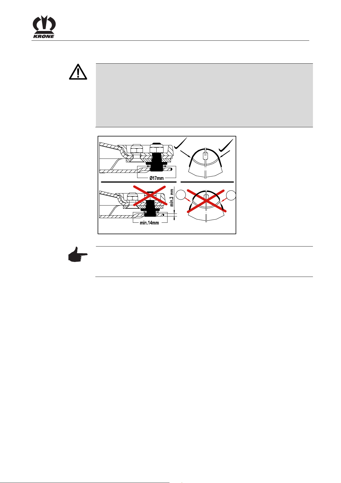
Pos: 27.27.12 /BA/Wartung/Mähwerke/R egelmäßige K ontrolle der Bla ttfedern @ 0\ mod_1197268 274609_78.doc @ 16464
10.9.4 Periodical Inspection of the Leaf Springs
Maintenance
Danger!
Worn application seam on the leaf springs.
Effect: Danger to life or serious injuries.
• Check the leaf springs for damages at least once a day or after contact
with foreign objects.
• The abrasion limit of the leaf springs will be achieved if the application
seam (1) is worn on one point.
1
1
EC 225 0
Fig. 29:
Pos: 27.27.13 /BA/-----Seitenumbruch---- -- @ 0\mod_ 1196175311226 _0.doc @ 416 5
Note
Warranty claim
Use only original Krone spare parts to replace the leaf springs.
57

Maintenance
Pos: 27.27.14 /BA/Wartung/Mähwerke/R egelmäßige K ontrolle der Mess erteller bz w. -trommeln @ 0\mod_11972 68487390_78.d oc @ 16483
10.9.5 Periodical Inspection of the Cutting Discs / Blade Drums
Danger!
Deformed Cutting Discs / Blade Drums
Effect: Danger to life or serious injuries.
• Check the cutting discs or blade drums for damages at least once per
day or after contact with foreign objects.
• In case of deformed cuttings discs or drums, the dimension of A = 48
mm must never be exceeded.
1
A
EC-0-211
Fig. 30:
Pos: 27.27.15 /BA/-----Seitenumbruch---- -- @ 0\mod_ 1196175311226 _0.doc @ 416 5
Note
Warranty claim
The cutting discs or drums must be replaced by Original Krone spare parts
only.
58

Pos: 27.27.16 /BA/Wartung/Mähwerke/ Verschleissgr enze für Aus waschungen @ 0\ mod_1197268 738875_78.doc @ 16502
10.9.6 Abrasion Limit
Maintenance
Danger!
Abrasion on the cutting discs / blade drums
Effect: Danger to life or serious injuries.
• The abrasion limit (2) will be achieved if the min. material thickness of 3
mm is no longer given.
2
2
EC-226-0
Fig. 31:
Pos: 27.27.17 /BA/-----Seitenumbruch---- -- @ 0\mod_ 1196175311226 _0.doc @ 416 5
Note
Warranty claim
If cutting discs or blade drums show deformations or wear in form of
abrasions (2) or similar, these components have to be replaced by Original
Krone spare parts .
59

Maintenance
Pos: 27.27.18 /Überschriften/Überschrift en 2/K-O/Messer wechsel an M essertellern @ 0\mod_119 7269068562_ 78.doc @ 165 21
10.10 Blade Changing on Cutting Discs
Pos: 27.27.19 /BA/Sicherheit/Gefahre nhinweise/Mä hwerke/Schnell roti erende Messert eller/Messertro mmeln_1 @ 0\mod_1197 017696736_78.d oc @ 16001
Pos: 27.27.20 /BA/Sicherheit/Gefahre nhinweise/Mä hwerke/Sich lösen de Mähklinge n @ 0\mod_119 7269483265_7 8.doc @ 1654 0
Danger!
Rapidly rotating cutting discs/blade drums.
Effect: Danger to life or serious injuries.
• Switch off the engine and remove the ignition key.
• The cutting discs/blade drums continue to run!
• Do not leave the driver’s cab until the cutting discs/blade drums have
come to a complete stop.
Danger!
Cutter blades coming loose
Effect: Danger to life or serious injuries.
• After changing the blades check that they fit perfectly and that they can
move freely.
• Whenever a blade is changed, also inspect the fasteners and replace
them, if necessary!
• Always replace missing and damaged blades in sets to prevent
unbalanced rotation!
Pos: 27.27.21 /BA/-----Seitenumbruch---- -- @ 0\mod_ 1196175311226 _0.doc @ 416 5
• Never mount unevenly worn blades on a drum/disc!
60
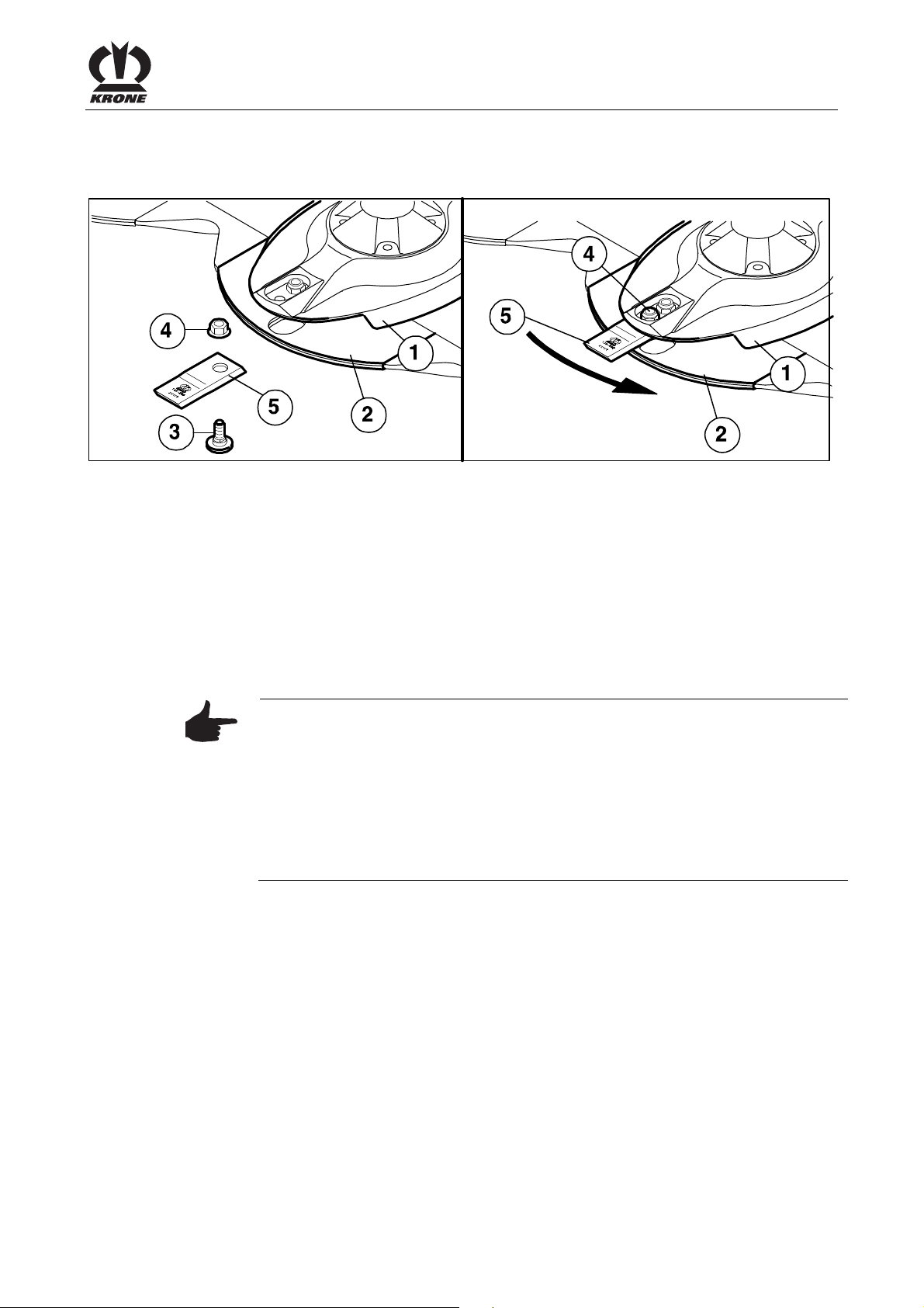
Pos: 27.27.22 /Überschriften/Überschrift en 3/K-O/Messersc hraub verschluß @ 0\m od_1197270941 296_78.doc @ 1 6578
10.10.1 Blade Screw Connection
Pos: 27.27.23 /BA/Wartung/Mähwerke/ Beschreibung M esserwechsel M esserschrau bverschluss @ 0\mod_119727 0197046_78.d oc @ 16559
Fig. 32:
• Clean the area.
• Remove damaged or worn blades.
• To fit the blades, insert the blade (5) between the wear plate (2) and the cutting disc (1).
• Insert the retaining bolt (3) from below through the wear plate, the blade and the cutting
disc.
• Place the hex nut (4) on the retaining bolt from above and tighten it firmly. (for tightening
torque see chapter entitled "Torques")
• Repeat this process for all blades, even on the blade drums.
• After fitting the blades, fold the protective device down again.
Note
Maintenance
EC-0-250
Pos: 27.27.24 /BA/-----Seitenumbruch---- -- @ 0\mod_ 1196175311226 _0.doc @ 416 5
• The cutter blades of anticlockwise rotating cutting discs / blade drums
are different than those of clockwise rotating ones. Make certain the
direction of rotation is correct when installing!
• The arrow on the cutter blades must match the direction of rotation of
the corresponding cutting discs / blade drums.
• The hex nut (4) used to secure the retaining bolts must not be used
more than once.
Order No. for clockwise rotating blade: 139-889
Order No. for anticlockwise rotating blade: 139-888
61

Maintenance
Pos: 27.27.25 /Überschriften/Überschrift en 3/K-O/Messersc hnellversc hluß @ 0\mod_ 11972710198 59_78.doc @ 16597
10.10.2 Blade Quick-Fit Device
Pos: 27.27.26 /BA/Wartung/Mähwerke/ Beschreibung M esserwechsel M esserschn ellverschluss @ 0 \mod_119727 1100500_78. doc @ 16616
Fig. 33:
2
3
4
5
EC-251-0
• Clean the area.
• Remove damaged or worn blades.
• Push the special tool (1) {blade key} between the cutter disc (4) and leaf spring (3) and
press down with one hand.
• Guide a new blade (2) onto the retaining bolt and allow the blade key to return upwards.
• After fitting the blades, fold the protective device down again.
Note
Pos: 27.27.27 /BA/-----Seitenumbruch---- -- @ 0\mod_ 1196175311226 _0.doc @ 416 5
• The cutter blades of anticlockwise rotating cutting discs / blade drums
are different than those of clockwise rotating ones. Make certain the
direction of rotation is correct when installing!
• The arrow on the cutter blades must match the direction of rotation of
the corresponding cutting discs / blade drums.
• The hex nut (4) used to secure the retaining bolts must not be used
more than once.
Order No. for clockwise rotating blade: 139-889
Order No. for anticlockwise rotating blade: 139-888
62

Pos: 27.27.28 /BA/Wartung/Mähwerke/ Stoßkanten ern euern @ 0\mo d_119727132 0468_78.doc @ 16636
10.11 Replacing the linings
Maintenance
Caution!
If the linings are checked irregularly.
Effect: Damage to the machine
• Always check the mowing unit for damaged linings prior to start-up and
replace linings, if necessary!
• Adjust the welding current and the welding material to the cutter bar
material and to the lining or carry out a trial welding if necessary.•
EC-0-012
Fig. 34:
• Open the welding seams of the old lining.
• Remove the lining
• Deburr the contact surface.
EC-252-0
Fig. 35:
• Adapt the new lining (3).
• Weld short I seams on the upper surface of the cutter bar in the areas marked (1) (each
should be approx. 30 mm).
• Do not weld the edges (2).
• On the lower surface of the cutter bar, weld the lining (3) to the cutter bar along the
whole length in area (5).
Pos: 27.28 /BA/-----Seitenumbruch---- -- @ 0\mod_1 196175311226_ 0.doc @ 4165
• Do not weld the edges (4).
63

Maintenance
Pos: 27.29.1 /Überschriften/Überschrifte n 2/K-O/Kreis elnabe mit Sch ersicherung ( optional) @ 4\ mod_1213097920 976_78.doc @ 86356
10.12 Rotary hub with shear fuse (optional)
Pos: 27.29.2 /BA/Wartung/Mähwerke/Sc hersicherung/Bild Mähholm A ufstellung EC 2 8/32 P EC 28/ 32M @ 15\m od_12324484 31683_78.doc @ 174012
Fig. 36:
Pos: 27.29.3 /BA/-----Seitenumbruch--- --- @ 0\mod_1 196175311226_ 0.doc @ 4165
64

Pos: 27.29.4 /BA/Sicherheit/Gefahren hinweise/Mäh werke/Schnell rotier ende Messer teller/Messertr ommeln_1 @ 0\mod_11970 17696736_78.do c @ 16001
Maintenance
Pos: 27.29.5 /BA/Wartung/Mähwerke/Sc hersicherung/L egende Mä hholm Aufstellu ng EasyCut´s @ 4\mod_12130 98609195_78. doc @ 86463
Pos: 27.29.6 /BA/Wartung/Mähwerke/Sc hersicherung/B eschreibung S chersicherung @ 3\mod_12 04205493155_7 8.doc @ 6996 4
Pos: 27.29.7 /BA/-----Seitenumbruch--- --- @ 0\mod_1 196175311226_ 0.doc @ 4165
Danger!
Rapidly rotating cutting discs/blade drums.
Effect: Danger to life or serious injuries.
• Switch off the engine and remove the ignition key.
• The cutting discs/blade drums continue to run!
• Do not leave the driver’s cab until the cutting discs/blade drums have
come to a complete stop.
Explanation of abbreviations:
A= Direction of rotation "A" to the middle
B= Direction of rotation "B" in pairs
RZ= Central bearing housing (clockwise threading), without identifying groove.
RE= Eccentric bearing housing (clockwise threading, without identifying groove).
LZ= Central bearing housing (anticlockwise threading), with identifying groove.
LE= Eccentric bearing housing (anticlockwise threading), with identifying groove.
For protection against overload on the mowing units, the rotary hubs (1) are secured with nuts
(2) and shear pins (3).
If the machine strikes obstacles (for example stones), the 2 shear pins in the rotary hub will be
sheared off. The rotary hub and nut turn upward on the pinion shaft.
• The cutting discs or drums which move crop to the left (as seen in the direction of travel)
(LE/LZ) have left-handed threading.
• The cutting discs or drums which move crop to the right (in the direction of travel)
(RE/RZ) have right-handed threading.
To distinguish between right-hand (clockwise) threading (RE/RZ) and left-hand (anti-clockwise)
threading (LE/LZ), the nuts (2) and pinion shaft (4) for left-hand threading (LE/LZ) have a
distinctive grove (a, b).
• Left-handed (LE/LZ) nuts (2) have distinctive grooves (a) on the bevel.
• Left-handed (LE/LZ) pinion shafts (4) have a distinctive groove (b) on the face.
65

Maintenance
Pos: 27.29.8 /BA/Wartung/Mähwerke/Sc hersicherung/N ach dem Absc heren EasyCu t @ 3\mod_1 20420515460 8_78.doc @ 699 44
10.12.1 After Shearing Off
Caution!
Correct installation position of the bearing housing not observed.
Effect: Damage to the machine
• Right rotating (RE/RZ) cutting discs and drums always have righthanded pinion shafts and nuts (no groove mark on the pinion shaft and
nut).
• Left rotating (LE/LZ) cutting discs and drums always have left-handed
pinion shafts and nuts (with groove mark on the pinion shaft and nut).
7
8
a
2
9
3a
3
3a
Fig. 37:
3a
3
d
b
1
4
c
10
EC-255-0
66

Pos: 27.30 /BA/-----Seitenumbruch---- -- @ 0\mod_1 196175311226_ 0.doc @ 4165
Maintenance
• Remove the cutting disc or drum.
• Remove retaining ring (7).
• Unscrew the hexagon head bolts (8).
• Use the special key (10) included with delivery to remove the nut (2).
• Remove the hub (1).
• Remove the damaged shear pins (3).
• Check the nut and hub for damage. Replace damaged parts with KRONE original
replacement parts.
• Fill the space above the bearing with grease (c).
• Place the hub on the pinion shaft.
• Drive the new shear pins (3) through the hub (1) and shaft (4).
Note
Note the position of the shear pins!
• Drive the shear pins (3) into the hole from outside until the end of the
pin reaches the surface of the hub (d).
• he slots of the shear pins (3) must be mounted facing each other
horizontally (see detail (I)).
• Install the nut (2) using the special key (10) included with delivery (tighten to a tightening
torque of 300 Nm).
• Install and tighten the hexagon head bolts (8) with detent edged washers.
• Install the retaining ring (7).
• Install the cutting disc (5) or blade drum (6).
67

Maintenance – lubrication chart
Pos: 27.31.1 /Überschriften/Überschrifte n 1/U-Z/Wartung - Schmierpl an @ 0\mod_1 19735930419 8_78.doc @ 1 8232
11 Maintenance – lubrication chart
Pos: 27.31.2 /Überschriften/Überschrifte n 2/P-T/Speziell e Sicherheits hinweise @ 0\ mod_1196660 495760_78.doc @ 9134
11.1 Special Safety Instructions
Pos: 27.31.3 /BA/Sicherheit/Gefahren hinweise/Mäh werke/Gefahr W artung allge mein EasyCut @ 1 1\mod_12236 20198301_78.d oc @ 148349
Danger!
When performing repair, maintenance or cleaning work on the machine, or in
the case of technical intervention, drive elements may start moving (caution,
the cutting discs continue to run).
Effect: Danger to life, injuries or damage to the machine.
• Move the machine to the working position and lower it to the ground
• Switch off the tractor engine and remove the ignition key.
• Secure the tractor against accidental start-up and against rolling.
• Switch off the PTO and disengage it.
• After repair, maintenance, cleaning work or technical modifications are
complete, mount all protective coverings and safety devices again
properly.
• Avoid skin contact with oils, greases, cleaning agents and solvents.
• In the event of injuries or burns due to oils, cleaning agents or solvents,
contact a doctor immediately.
Pos: 27.31.4 /Überschriften/Überschrifte n 2/F-J/Gele nkwelle @ 0\ mod_1199781879 794_78.doc @ 34542
11.2 PTO shaft
Pos: 27.31.5 /BA/Wartung/EasyCut/A bschmieren G elenkwelle EasyCu t @ 3\mod_1 20473024150 8_78.doc @ 7 2667
Fig. 38:
Lubricate the PTO shafts at the intervals indicated in the drawing with a multi-purpose grease.
Pos: 27.31.6 /BA/-----Seitenumbruch--- --- @ 0\mod_1 196175311226_ 0.doc @ 4165
Follow the operating instructions of the PTO shaft manufacturer.
• All other safety instructions must also be followed to avoid injuries and
accidents.
68

Pos: 27.31.7 /Überschriften/Überschrifte n 2/P-T/Schmi erplan @ 0\m od_11973618 29026_78.doc @ 18495
11.3 Lubrication Chart
Pos: 27.31.8 /Abkürzungen /Abkürzung en sprachneutral/ EasyCut/Ea syCut 28 P; Eas yCut 28M; E asyCut 32 P @ 1 0\mod_12217 42126208_0.d oc @ 137262
(EasyCut 28 P; EasyCut 28 M; EasyCut 32 P)
Pos: 27.31.9 /BA/Wartung/EasyCut/Sc hmierpläne/Sch mierplan Bild EC 28/32 @ 1 0\mod_12217 41987395_78.doc @ 137240
20h
Maintenance – lubrication chart
20h
Fig. 39:
Pos: 28 /BA/-----Seitenumbruch------ @ 0\mod_11961 75311226_0.d oc @ 4165
EC-228-0
69

Placing in Storage
Pos: 29.1 /Überschriften/Überschriften 1/ A-E/Einlager ung @ 0\mod_ 11973854591 20_78.doc @ 19966
12 Placing in Storage
Pos: 29.2 /BA/Einlagerung/EasyCut/Einlag erung allge mein ohne B ereifung @ 3\m od_1204731079 008_78.doc @ 72747
Before placing the machine in winter storage, clean inside and outside thoroughly. If you use a
high-pressure cleaner to do this. do not keep a stream of water directed at bearing points. After
cleaning is completed, lubricate all lubrication points. Do not wipe off any grease that comes out
of bearing points. The hardened grease will provide additional protection against moisture.
Oil all joint points!
Check all movable components such as deflector rollers, joints, tension rollers, etc. to make
certain they move easily. If necessary remove, clean, grease and remount. If necessary,
replace with new parts.
Use only original KRONE replacement parts.
Disassemble the PTO shaft. Lubricate the inner tubes and the guard tube with grease. Grease
the lubrication points on the cross joint and on the bearing rings of the guard tubes.
Touch up damaged paint and preserve all uncoated areas thoroughly with rust protection agent.
Park the machine in a dry location, but not in the vicinity of artificial fertilisers or livestock
buildings.
Perform the necessary repair tasks during the time immediately after the harvest season. Draw
up a list of all replacement parts you will need. This will make it easier for your KRONE dealer to
process your orders and you will be certain that your machine will be ready for use at the
Pos: 29.3 /BA/-----Seitenumbruch------ @ 0\mod_11 96175311226_0.d oc @ 4165
beginning of the next season.
70

Pos: 29.4 /Überschriften/Überschriften 1/ U-Z/Vor Begin n der neuen Saison @ 4\ mod_121127264 7559_78.doc @ 82867
13 Before the Start of the New Season
Pos: 29.5 /Überschriften/Überschriften 2/ P-T/Spezielle Sicherheitshi nweise @ 0\m od_11966604 95760_78.doc @ 9 134
13.1 Special Safety Instructions
Pos: 29.6 /BA/Sicherheit/Gefahrenhinweis e/Mähwer ke/Gefahr Wartung allgemein E asyCut @ 11\mo d_122362019 8301_78.doc @ 148349
Danger!
When performing repair, maintenance or cleaning work on the machine, or in
the case of technical intervention, drive elements may start moving (caution,
the cutting discs continue to run).
Effect: Danger to life, injuries or damage to the machine.
• Move the machine to the working position and lower it to the ground
• Switch off the tractor engine and remove the ignition key.
• Secure the tractor against accidental start-up and against rolling.
• Switch off the PTO and disengage it.
• After repair, maintenance, cleaning work or technical modifications are
complete, mount all protective coverings and safety devices again
properly.
• Avoid skin contact with oils, greases, cleaning agents and solvents.
• In the event of injuries or burns due to oils, cleaning agents or solvents,
contact a doctor immediately.
Before the Start of the New Season
Pos: 29.7 /Überschriften/Überschriften 2/ P-T/Probela uf @ 0\mod_11 96782963921 _78.doc @ 14 908
13.2 Test run.
Pos: 29.8 /BA/Sicherheit/Gefahrenhinweis e/Mähwer ke/Probelauf Einz ahl @ 11\mod _1223615241 207_78.doc @ 1 48217
Pos: 29.9 /BA/-----Seitenumbruch------ @ 0\mod_11 96175311226_0.d oc @ 4165
• All other safety instructions must also be followed to avoid injuries and
accidents.
Danger!
Testing the machine after repair, maintenance or cleaning work and after
technical intervention.
Effect: Danger to life or serious injuries
• The mowing unit must be in working position
• Do not switch on the drives until the mowing unit is resting on the
ground and you are absolutely sure that neither persons, animals nor
objects are in the danger zone.
• Start a trial run of the machine only from the driver’s seat.
71

Before the Start of the New Season
Pos: 29.10 /BA/Einlagerung/EasyCut/V or der Saisaon ohne Bereifung @ 3\mod_ 1204731533226 _78.doc @ 7276 7
• Lubricate the machine thoroughly. Remove any condensation water which may have
collected in the bearings.
• Check oil level in the gearbox(es) and top up if necessary.
• Check all screws to make certain they are tight or retighten them if necessary.
• Check all electrical connection cables and the lighting. Repair or replace if necessary.
• Check the entire setting of the machine and correct if necessary.
• Re-read the operating instructions thoroughly.
Pos: 30 /BA/-----Seitenumbruch------ @ 0\mod_11961 75311226_0.d oc @ 4165
Note
Use vegetable oils and greases.
72

Pos: 31 /Überschriften/Überschriften 1/P-T/ Sonderausst attung @ 2\m od_120280 8469779_78.doc @ 61649
14 Special equipment
Pos: 32 /Überschriften/Überschriften 2/P-T/ Spezielle Sic herheitshin weise @ 0\mod_ 11966604957 60_78.doc @ 9134
14.1 Special Safety Instructions
Pos: 33 /BA/Sicherheit/Gefahrenhin weise/Mähwerke/G efahr Wartu ng allgemein E asyCut @ 11\ mod_122362019 8301_78.doc @ 148349
Danger!
When performing repair, maintenance or cleaning work on the machine, or in
the case of technical intervention, drive elements may start moving (caution,
the cutting discs continue to run).
Effect: Danger to life, injuries or damage to the machine.
• Move the machine to the working position and lower it to the ground
• Switch off the tractor engine and remove the ignition key.
• Secure the tractor against accidental start-up and against rolling.
• Switch off the PTO and disengage it.
• After repair, maintenance, cleaning work or technical modifications are
complete, mount all protective coverings and safety devices again
properly.
• Avoid skin contact with oils, greases, cleaning agents and solvents.
• In the event of injuries or burns due to oils, cleaning agents or solvents,
contact a doctor immediately.
Special equipment
Pos: 34 /BA/-----Seitenumbruch------ @ 0\mod_11961 75311226_0.d oc @ 4165
• All other safety instructions must also be followed to avoid injuries and
accidents.
73

Special equipment
Pos: 35.1 /BA/Sonderausstatung/Eas yCut/Umbau auf sc hmalere Sch wadablage EC 28/32 M @ 13\mod_122692 3435912_78.doc @ 166497
14.2 Conversion to narrower swathing (EasyCut 28 M, EasyCut 32 M)
5
EasyCut 28M
EasyCut32M
4
Fig. 40:
• Remove the cutting discs (5) and covers (6).
• Remove cover (3) of mower drum (4). Mount the mower drum with fastening bolts and the
• Mount the cover (3) on the mower drum (4).
1
4
6
5
4
6
3
4
4
detent edged washers of the disassembled cutting discs (6).
Note
2
3
4
EC-281-0
74
Keep the cover (5) and cutting disc (6) in a suitable place for later
reinstallation.
Warning
Mower drum incorrectly installed
Effect: Damage to the machine
Make certain the mower drums are installed correctly! The installed mower
drums (4) must be installed at a 90-degree offset to the adjacent mower drums
/ cutting discs.

Special equipment
• Install the plates (1,2). Make certain when attaching the plates that the distance from the
rubber pads (7) to the mower drums is at least 3 mm.
Note
Reinstallation is in the reverse order
Before starting up the machine again, make certain to check the cutter blades,
retaining bolts, cutting discs, and drums as well as the linings
• See Maintenance section “Checking the Cutter Blades and Retaining
Bolts”.
• See Maintenance section “Periodical Inspection of Cutting Discs and
Drums."
Pos: 35.2 /BA/-----Seitenumbruch------ @ 0\mod_11 96175311226_0.d oc @ 4165
• See Maintenance section “Replacing the Linings".
75

Special equipment
Pos: 35.3 /BA/Sonderausstatung/Eas yCut/Umbau für s teiles Bergab mähen EC 28 M /32M @ 13\ mod_1226927 794381_78.doc @ 166544
14.3 Conversion for mowing steep slopes (EasyCut 28 M, EasyCut 32 M)
1
4
EasyCut 28M
Fig. 41:
• Remove plates (1,2)
• Remove cover (3) of mower drum (4).
• Remove mower drum (4).
2
4
3
3
5
6
5
6
EasyCut32M
EC-254-1
Note
Keep the plates (1,2), cover (3) and mower drums (4) in a protected place for
later reinstallation.
Warning
Cutting disc installed incorrectly
Effect: Damage to the machine
Make certain the cutter discs are installed correctly! The installed cutting
discs (5) must be installed at a 90-degree offset to the adjacent mower drums
/ cutting discs.
76

===== Ende der Stückliste =====
Special equipment
• Mount the cutting discs (5) and covers (6). To do this, reuse the fastening bolts and
detent edged washers of the mower drums that were removed.
Note
Follow the steps in the reverse order for reinstallation (see also Chapter
"Conversion to Narrower Swathing").
Before starting up the machine again, make certain to check the cutter blades,
retaining bolts, cutting discs, and drums as well as the linings
• See Maintenance section "Checking the Cutter Blades and Retaining
Bolts".
• See Maintenance section "Periodical Inspection of Cutting Discs and
Drums."
• See Maintenance section "Replacing the Linings".
77

. . . konsequent, kompetent
Maschinenfabrik
Bernard Krone GmbH
Heinrich-Krone-Straße 10, D-48480 Spelle
Postfach 11 63, D-48478 Spelle
Phone +49 (0) 59 77/935-0
Fax +49 (0) 59 77/935-339
Internet: http://www.krone.de
eMail: info.ldm@krone.de
 Loading...