

Operating instructions
150 000 054 00 EN
Maize header
EASYCOLLECT 6000
EASYCOLLECT 7500
EASYCOLLECT 9000
(Machine No. 535 500 or higher)
Dear Customer:
These are the operating instructions for the KRONE product that
you have purchased.
These operating instructions contain important information for
the correct use and safe operation of the machine.
Should these operating instructions have become unusable
completely or partially for any reason, you can obtain
replacement operating instructions for your machine by stating
the number quoted on the reverse.
EC Declaration of Conformity
corresponding to the EC Directive 98/37/EC
We Maschinenfabrik Bernard Krone GmbH
Heinrich-Krone-Str. 10, D-48480 Spelle, Germany
declare in our sole responsibility that the product
Krone Maize Header
Types: EasyCollect 6000; EasyCollect 7500; EasyCollect 9000
tto which this declaration refers corresponds to the relevant basic safety and health requirements of the
EC Directive 98/37/EC.
Spelle, 13.05.04
(Dr.-Ing. Josef Horstmann, Managing Director)
(Wolfgang Ungruh, Head of Quality Assurance)

Contents
Contents
1 General aspects ................................................................................ I -1
1.1 Intended use............................................................................................................. I -1
1.2 Technical data .......................................................................................................... I -1
1.2.1 General aspects ...................................................................................................... I -1
1.2.2 Address of the manufacturer.................................................................................... I -1
1.2.3 Declaration .............................................................................................................. I -1
1.2.4 Designation ............................................................................................................. I -1
1.2.5 Information for enquiries and orders ........................................................................ I -1
1.2.6 Intended use............................................................................................................ I -2
1.2.7 Technical data .............. ...................... ..................................................................... I -2
2 Safety................................................................................................ IV -1
2.1 Identifying important information in the operating instructions .................................. IV -1
2.2 Safety instructions and accident prevention regulations .......................................... IV -1
2.2.1 Personnel qualification and training ...................................................................... IV -1
2.2.2 Dangers in failure to comply with the safety instructions ....................................... IV -1
2.2.3 Safety-conscious work practices ........................................................................... IV -1
2.2.4 Safety and accident prevention regulations........................................................... IV -2
2.2.5 Attached devices ................................................................................................... IV -3
2.2.6 PTO operation ....................................................................................................... IV -3
2.2.7 Hydraulic system ................................................................................................... IV -3
2.2.8 Maintenance.......................................................................................................... IV -4
2.2.9 Unauthorised conversion/modification and Manufacture of spare parts ................ IV -4
2.2.10 Impermissible modes of operation......................................................................... IV -4
2.3 Safety instructions on the machine.......................................................................... IV -5
2.3.1 Location of the warning pictograms on the machine.............................................. IV -6
2.3.2 Location of the general warning signs on the machine.......................................... IV -8
3 Start-up ............................................................................................. III -1
3.1 S pecial safety instructions ....................................................................................... III -1
3.2 S top points.............................................................................................................. II I -1
3.3 Storage ................................................................................................................... III -1
3.4 Attaching................................................................................................................. III -2
3.4.1 Adjusting the adapter frame................................................................................... III -2
3.4.2 Pendulum frame .................................................................................................... III -3
3.4.3 Coupling................................................................................................................ III -3
3.5 T ransport position.................................................................................................... III -5
3.5.1 Folding in the tubular bar on the right/left .............................................................. III -5
3.5.2 Swinging the maize header up.............................................................................. III -5
3.5.3 Parking supports in transport position on the right/left ........................................... III -6
3.5.4 Installing guard on the right/left.............................................................................. III -6
3.5.5 Connecting indicators and position lights on the right/left...................................... III -6
3.5.6 Installing the front guard ........................................................................................ III -7
3.5.7 Road travel ............................................................................................................ III -7
3.6 Working position..................................................................................................... III -7
3.6.1 Removing the protective cover .............................................................................. III -7
3.6.2 Adjusting skids ...................................................................................................... III -7
3.6.3 Folding up the tubular bar on the right/left ............................................................. III -8
3.6.4 Adjusting the plant dividers ................................................................................... III -8

Contents
3.7 Using the machine for work ..................................................................................... III -9
3.7.1 Special safety instructions..................................................................................... III -9
3.7.2 Using the maize header ........................................................................................ III -9
3.7.3 Lifting gear spacing control (optional).................................................................... III -9
3.7.4 Autopilot (optional) .............................................................................................. III -10
3.8 Detaching ............................................................................................................. III -10
4 Maintenance.................................................................................... IV -1
4.1 S pecial safety instructions ...................................................................................... IV -1
4.2 General aspects..................................................................................................... IV -1
4.2.1 Tightening torques on the aluminium gears .......................................................... IV -2
4.3 Gearboxes............................................................................................................. IV -3
4.3.1 Lubricant quantities and designations for gearboxes ............................................ IV -3
4.3.2 Checking the oil level and changing the oil in the main angular gearbox.............. IV -3
4.3.3 Checking the oil level and changing the oil in the transfer gearbox (right/left)....... IV -4
4.3.4 Checking the oil level and changing the oil in the collector gearbox (right/left) ..... IV -4
4.3.5 Checking the oil level and changing the oil in the angular gearbox (right/left)....... IV -5
4.3.6 Checking the oil level and changing the oil in the dresser gearbox (right/left)....... IV -6
4.4 Laid maize worm drive belt (right / left).................................................................... IV -7
4.4.1 Checking the drive belt tension ............................................................................. IV -7
4.4.2 Correcting the drive belt tension............................................................................ IV -7
4.5 Collector pre-tension (right / left)............................................................................. IV -8
4.5.1 Checking the collector pre-tension ........................................................................ IV -8
4.5.2 Correcting the collector pre-tension....................................................................... IV -8
4.6 Scraper (right / left)................................................................................................. IV -9
4.6.1 Adjusting the scraper............................................................................................. IV -9
4.7 Tips...................................................................................................................... IV -10
4.7.1 Adjusting the side tips (right / left)........................................................................ IV -10
4.7.2 Adjusting the central tip ....................................................................................... IV -10
4.7.3 Replacing tips ..................................................................................................... IV -10
4.8 Removing the upper insert finger ...........................................................................IV -11
4.9 Installing PTO shafts ..............................................................................................IV -1 1
4.10 Hydraulic hose lines ..............................................................................................IV -1 1
4.11 Changing blades.................................................................................................. IV -12
4.11.1 Changing bow and step blades........................................................................... IV -12
4.11.2 Changing cutting blades ...................................................................................... IV -13
4.11.3 Changing dresser segments (right / left) .............................................................. IV -13
4.11.4 Changing scraper blades (right / left)................................................................... IV -14
4.12 Lubrication ........................................................................................................... IV -15
4.12.1 PTO shafts........................................................................................................... IV -15
4.12.2 Lubrication chart.................................................................................................. IV -16
4.13 Storing when not in use......................................................................................... IV -17
A1 Commissioning.................................................................................A -1
A1.1 Fitting the additional weights ................................................................................... A -1
A1.2 Fitting the discharge extension (only for EasyCollect 7500; EasyCollect 9000) ........ A -2
I - 1
General aspects
1 General aspects
These operating instructions contain basic information
that has to be observed in mounting, operation and
maintenance. For this reason these operating
instructions must be read by the staff prior to operation
and must be accessible to the staff at all time.
Not only must the general safety instructions listed
under this main item of safety be complied with, but
also the special safety instructions inserted under the
other main items.
1.1 Intended use
The Krone EASYCOLLECT 6000, EASYCOLLECT
7500 and EASYCOLLECT 9000 maize header is a
harvesting attachment with adapter frame for
attachment to forage harvesters and is used for
harvesting maize and other forage crop with stalks
independently of the rows.
1.2 Technical data
1.2.1 General aspects
These operating instructions apply to the
EASYCOLLECT 6000; EASYCOLLECT 7500 and
EASYCOLLECT 9000 maize header.
1.2.2 Address of the manufacturer
Maschinenfabrik Bernard Krone GmbH
Heinrich-Krone-Str. 10
D-48480 Spelle (Germany)
Telephone: 0 59 77/935-0
Fax: 0 59 77/935-339
Email: info.ldm@krone.de
1.2.3 Declaration
EC Declaration of Conformity
corresponding to the EC Directive
See the inside of the title page.
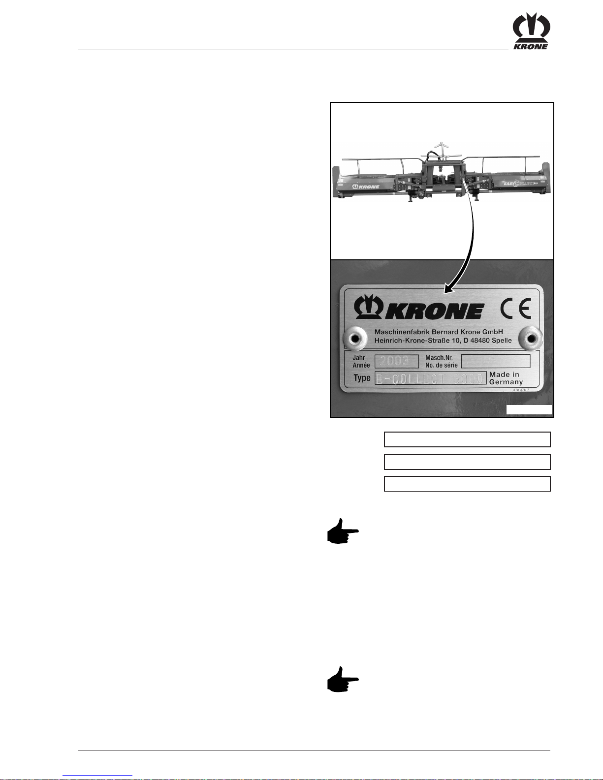
1.2.4 Designation
The rating plate is located on the adapter frame on the right.
Year
Mach. No.
Type
The entire designation has
documentary value and may not be
modified or made indecipherable!
1.2.5 Information for enquiries and orders
When enquiring about the machine and ordering spare
parts, state the type designation, the Machine ID No.
and the year of manufacture of the machine.
Authentic spare parts and accessories
authorised by the manufacturer
increase safety. The use of other parts
may void the liability for any
consequences.
EC200020

I - 2
General aspects
1.2.6 Intended use
The Krone EASYCOLLECT 6000, EASYCOLLECT
7500 and EASYCOLLECT 9000 may be attached only
to carrier vehicles for which the relevant adapter frame
is released (observe operating permission of the carrier
vehicle).
It is built exclusively for customary use in agricultural
work (use as intended), see also Section 1.1 Intended
use.
Any use extending beyond this is considered as not as
intended. The manufacturer is not liable for damage
resulting from this, the user alone bears the risk for
this.
The intended use shall also include the adherence to
the operating, maintenance and repair conditions set by
the manufacturer.
1.2.7 Technical data
All information, illustrations and technical data in
this operating manual are in keeping with the
latest state of technology at the point of
publication. Design modifications at any time
without statement of reason shall be reserved.
Type EASYCOLLECT 6000 EASYCOLLECT 7500 EASYCOLLECT 9000
Length (mm) 2190 2190 2190
Height in working position (mm) 1500 1500 1500
Total width in working position (mm) 6150 7650 9150
Working width (mm) 6000 7500 9000
Height, folded in (mm) 3000 3750 4500
Width, folded in (mm) 2900 2900 2900
Weight (kg) 2800 3200 3600
Power requirement (kW) 40 50 6 0
Drive speed (min-1) 300 - 700 300 - 700 300 - 700
Max. permissible operating pressure (bar) 200 20 0 20 0
Hydraulic connections 2x DW 2x DW 2x DW
Electr. connection (lighting) 7-pole 7-pole 7-pole
I - 3
General aspects
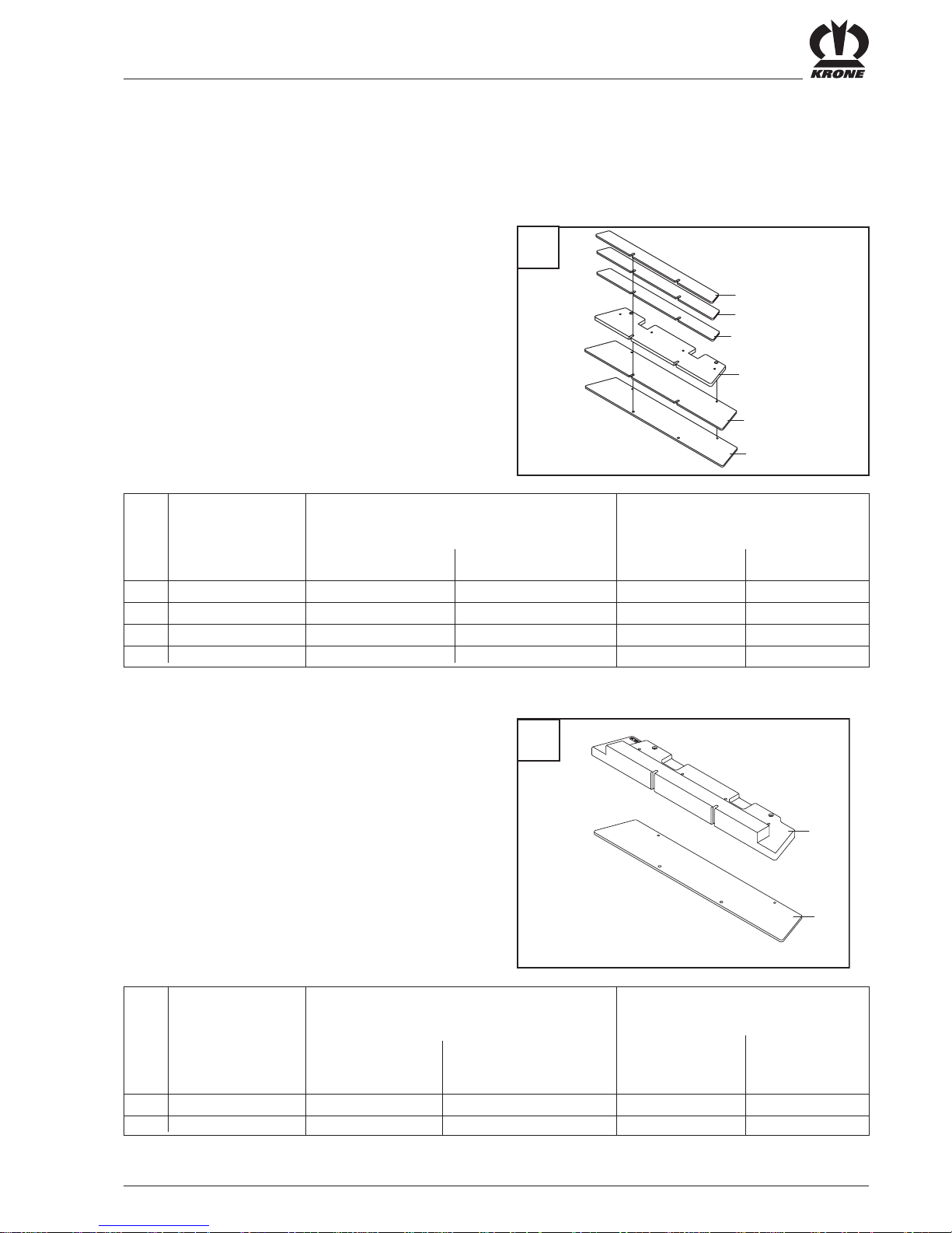
1.2.8 Additional weights on the BigX
To ensure safe and reliable operation of the selfpropelled forage harvester with the maize header
attached, especially in road traffic, additional weights
(Z) must be connected to the rear frame.
Item Designation of Number of weights Number of weights
weights for Big X V8 for BigX V12
EasyCollect 6000 EasyCollect 7500 EasyCollect 6000 EasyCollect 7500
1 Cover plate 3 3 3 3
2 Base plate 1 1 1 1
3 Intermediate plate 4 6 3 5
4 Floor plate 1 1 1 1
Steel design
Item Designation of Number of weights Number of weights
weights for Big X V8 for BigX V12
EasyCollect 6000 EasyCollect 7500 EasyCollect 6000 EasyCollect 7500
1 Main weight 1 1 1 1
2 Floor plate 2 4 1 3
Cast design
1
1
1
2
3
4
EC100665
Z
1
2
EC100666
Z

I - 4
General aspects

II - 1
Safety
2 Safety
2.1 Identifying important
information in the operating
instructions
Important safety instructions in the present operating
instructions are identified with the general hazard
symbol. Non-observance of these safety instructions
may result in personal injury.
Safety symbol according to DIN 4844 - W9
General notes on functions are identified as follows:
Instructions affixed directly to the machine must be
complied with and kept in a completely legible
condition by all means. If illegible, they must be
replaced.
2.2 Safety instructions and
accident prevention
regulations
2.2.1 Personnel qualification and training
The maize header may be used, maintained and
repaired only by persons who are familiar with it and
have been instructed about the dangers connected with
it. The area of responsibility, the competence and the
supervision of the personnel must be precisely defined
and regulated by the operator. If operating staff
members do not have the necessary knowledge, they
must be trained and instructed appropriately. The
operator must also ensure that the personnel
understands the full scope of the information and
instructions contained in the operating instructions.
Repair work not described in these operating
instructions may be performed by authorised specialist
workshops only.
2.2.2 Dangers in failure to comply with the
safety instructions
Failure to comply with the safety instructions may put
people, the environment and the machine at risk.
Failure to comply with the safety instructions can lead
to the forfeiture of any claims for damages.
Specifically, non-compliance can for example result in
the following hazards:
– Danger of persons due to not protected working
areas
– Failure of important functions of the machine
– Failure of specified methods for maintenance and
repair
– Danger of persons due to mechanical and chemical
effects
– Danger of the environment due to leakage of
hydraulic oil
2.2.3 Safety-conscious work practices
The safety instructions laid down in these operating
instructions, the existing accident prevention
regulations as well as any internal work, operating and
safety instructions of the operator must be complied
with.
The labour protection and accident protection
regulations of the responsible employers’ liability
insurance associations are binding.
The safety instructions of the vehicle manufacturer
must be complied with.

II - 2
Safety
Compliance with the relevant legal regulations is
mandatory in traffic on public roads (in the Federal
Republic of Germany, for example, the StVZO (Road
Traffic Type Approval Law and the StVO (Road Traffic
Law)).
2.2.4 Safety and accident prevention
regulations
1. In addition to the instructions in these operating
instructions, you must comply with the generally
applicable safety and accident prevention
regulations!
2. The affixed warning and safety signs provide
important information for safe operation. Heed them
for your own safety!
3. When using public roads, observe the relevant
regulations!
4. Before starting work make yourself familiar with all
devices and operating elements as well as with
their functions. It is too late once you have started
operating the machine!
5. The user should wear tightly fitting clothes. Avoid
loosely fitting clothing.
6. To avoid the danger of fire, keep the machine clean!
7. Before starting and before placing the machine in
operation, check the immediate surroundings!
(Children!) Ensure good visibility conditions!
8. Riding on the machine during working and transport
is not permitted.
9. Couple implements according to regulations and
attach and secure them only to the specified
devices.
10. When attaching and removing implements, position
the supports as required!
11. Special care is required when coupling and
uncoupling the maize header onto or from the
forage harvester!
12. Always attach ballast weights according to
regulations and to the mounting points provided!
13. Observe the permissible axle loads, the permissible
maximum weight and the transport dimensions!
14. Check and attach transport equipment, such as
lighting, warning signs and necessary protective
devices
15. Operating devices (ropes, chains, rods, etc.) of
remotely operated devices must be run so that they
do not trigger unintended movements in all
transport and working positions.
16. Ensure that the maize header is in the prescribed
condition for road travel and lock it according to the
instructions of the manufacturer!
17. Never leave the driver’s cab while the machine is
moving!
18. The speed must always be adapted to the
prevailing conditions! Avoid sudden changes of
direction when travelling uphill, downhill or when
crossing a slope!
19. Attached or suspended implements and ballast
weights affect the driving, steering and braking
response of the machine. For this reason, make
sure that you are able to steer the machine and
brake as required!
20. When cornering, take into account the large
overhang and/or flywheel mass of the device!
21. Take the maize header into operation only after all
protective devices have been attached and are in
their proper positions!
22. It is strictly forbidden to stay in the operating range
of the machine!
23. Do not stay in the turning and swivelling area of the
implement!
24. Hydraulic hinged frames may be operated only if no
persons are in the swivel area!
25. Parts operated by external power (e.g.
hydraulically) constitute crush and shear hazards!
26. Before leaving the forage harvester turn off the
engine and withdraw the ignition key!
27. Nobody may stay between the forage harvester and
the maize header without the vehicle being secured
against rolling off through the holding brake and/or
wheel chocks.
28. Observe all additional information related to safety
in the operating instructions for the forage
harvester.

II - 3
Safety
2.2.5 Attached devices
1. Special care is required when coupling and
uncoupling the maize header onto or from the
forage harvester!
2. The maize header must only be attached to the
forage harvester for which it is intended.
3. Work on the maize header must only be performed
when the engine is stopped and turned off and the
ignition key has been removed. All operating levers
must be in the neutral setting and no hydraulic
lines may be under pressure.
4. Only perform jobs under the maize header when it
is raised if it is securely supported.
5. The maize header must be brought basically into
the transport position on public roads and paths.
Attach protective cloths and front guard to the
maize header and connect the lighting.
2.2.6 PTO operation
1. Only PTO shafts specified by the manufacturer
may be used!
2. The protective tube and protective funnel of the PTO
shaft as well as the PTO shield - also on the implement end - must be attached and in proper condition!
3. Make sure that the required tube covers for PTO
shafts are in place in transport and working position!
4. Before installing or removing PTO shafts, switch off
the PTO shaft, turn the engine off and remove the
ignition key!
5. When using PTO shafts with an overload or free-wheel
couplings that are not covered by the protective equipment on the tractor, the ov erload or free-wheel couplings must be attached to the device!
6. Always make sure that the PTO shafts are mounted
correctly and secured properly!
7. Secure the PTO shaft guard against turning by hooking in the chains!
8. Before switching on the PTO shaft, make sure that
the selected PTO shaft speed of the tractor agrees
with the permissible speed of the device!
9. Before switching on the PTO shaft make sure that
no person is in the hazard area of the device!
10. Never switch on the PTO with the engine turned off!
11. While working with the PTO, nobody is permitted to
stay in the range of the turning PTO or PTO shaft.
12. Always switch off the PTO in the case of excessive
bending and if the PTO is not required!
13. Caution! After switching off the PTO, there is
danger due to the inertia of the flywheel mass! Do
not come near the implement during this time. Start
working on the machine only when it has come to a
complete halt.
14. Cleaning, lubricating or adjusting PTO driven
implements or the PTO shaftonly with PTO
disengaged, engine turned off and ignition key
withdrawn!
15. Place the uncoupled PTO shaft on the holder
provided!
16. After removal of the PTO shaft, fit the protective
sleeve on the PTO stump!
17. Immediately repair any damage before working with
the device.
2.2.7 Hydraulic system
1. The hydraulic system is under pressure!
2. When connecting hydraulic cylinders and motors
pay attention to the specified connection of the
hydraulic hoses!
3. When connecting the hydraulic hoses to the forage
harvester hydraulics, take care that the hydraulic
system is depressurised both on the tractor side
and on the device side!
4. When functions are connected hydraulically between
the forage harvester and the machine, coupling
sleeves and plugs should be identified so that faulty
operation is excluded! On changeover of the
connections reversed function (e.g. raising/lowering)
- Danger of accident!
5. Check hydraulic hose lines periodically and replace
them if they are damaged or worn through age! The
replacement hose lines must meet the technical
requirements of the device manufacturer!

II - 4
Safety
6. Use suitable tools when looking for leaks. Risk of
injury!
7. Fluids (hydraulic oil) exiting under high pressure
can penetrate the skin and cause severe injuries! In
the case of injuries, seek medical assistance
immediately. Danger of infection!
8. Before working on the hydraulic system,
depressurise the system and turn off the engine!
2.2.8 Maintenance
1. Always perform repair, maintenance and cleaning
work as well as troubleshooting only with the drive
switched off and the engine stopped!
- Remove the ignition key!
2. Periodically check nuts and bolts for firm seating
and tighten them if required!
3. When performing maintenance work with the
implement raised, always secure it with suitable
supporting elements!
4. When replacing work tools with cutting edges, use
suitable tools and protective gloves!
5. Dispose of oils, greases and filters according to
the regulations!
6. Before working on the electrical system, always
disconnect the power supply!
7. If protective equipment is subject to wear, check it
periodically and replace it in due time!
8. When performing electric welding work on the forage
harvester and mounted implements, disconnect
cables at the generator and battery!
9. Spare parts must at least correspond to the
technical requirements defined by the device
manufacturer!
This is guaranteed by original KRONE spare
parts!
2.2.9 Unauthorised conversion/
modification and Manufacture of
spare parts
Conversions or modifications of the machine are
permitted only with prior consultation with the
manufacturer. Authentic spare parts and accessories
authorised by the manufacturer increase safety. The
use of other parts may void the liability for any
consequences.
2.2.10 Impermissible modes of
operation
The operating safety of the delivered machine is
guaranteed only when it is used as intended in
compliance with the General chapter of the operating
instructions. The limit values stated in the data sheets
must not be exceeded under any circumstances.

II - 5
Safety
2.3 Safety instructions on the
machine
The KRONE maize header is equipped with all
necessary safety devices (protective devices). Not all
dangerous places on this machine can be completely
secured in reference to maintaining the functionality of
the machine.
Corresponding hazard information referring to residual
dangers is located on the machine.
We have implemented the hazard warnings in the form
of warning pictograms.
In the following, you will find important information on
the locations of these warning pictogram and an
associated description/supplementation!
Familiarise yourself with the
statement of the warning pictograms.
The adjacent text and the selected
location on the machine provide
information on the special danger
spots on the machine.

II - 6
Safety
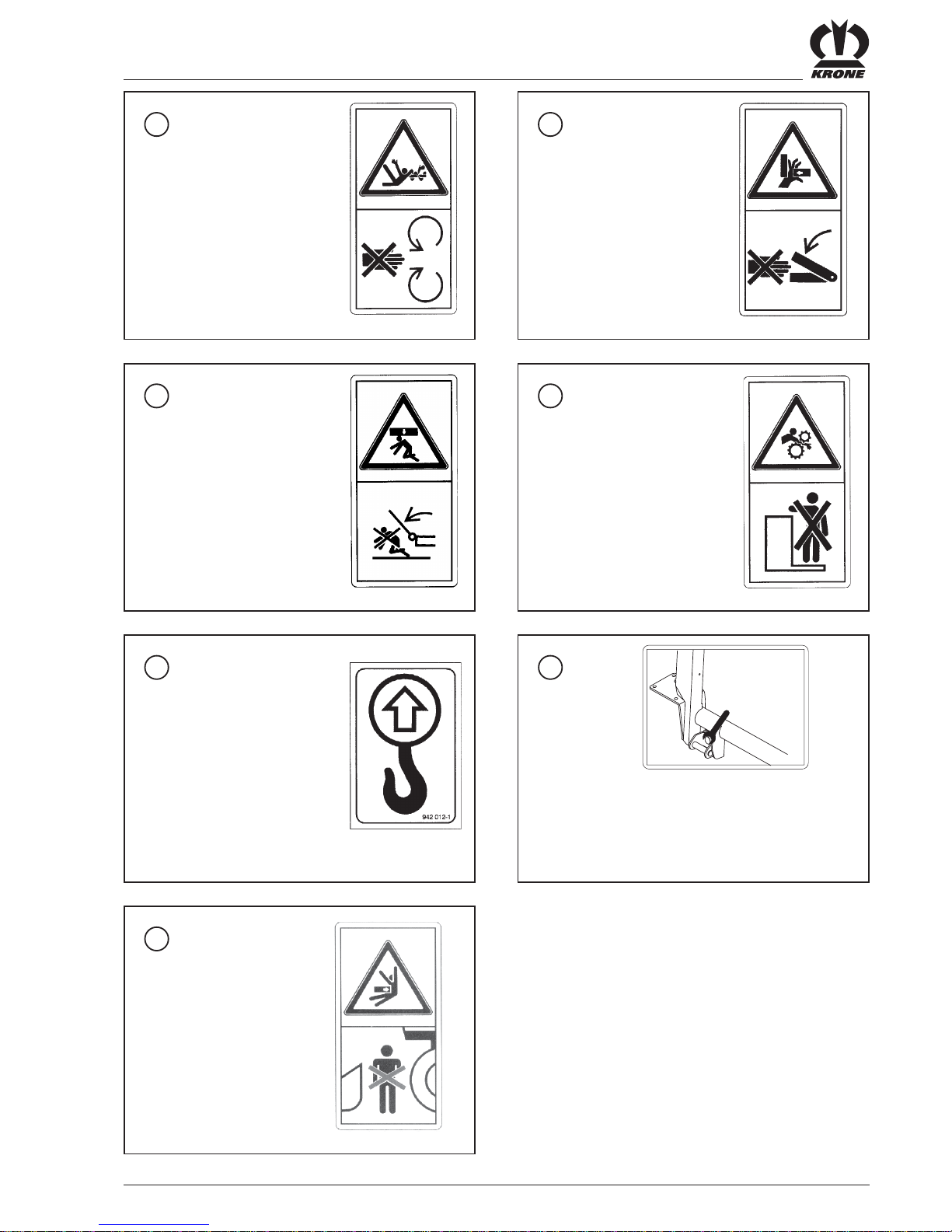
2.3.1 Location of the warning pictograms on the machine.
1
Before commissioning the
machine, read the
operating instructions and
safety instructions and
heed them.
Order no. 939 471-1 (1x)
2
Do not touch any moving
parts of the machine.
Wait until they have come
to a complete stop.
Order No. 939 410-2 (2x)
Spænd fastgørelsesskruerne
EC200021
2
4
4
6
6
6
5
8
5
3
2
3
1
9
9
7
7
II - 7
Safety
3
Danger due to revolving
worm auger.
Order No. 939 520-1 (2x)
4
Never reach into the area
where there is danger of
crushing as long as parts
may be in motion there.
Order No. 942 196-1 (2x)
6
Do not climb onto the
machine if the PTO shaft is
connected and the engine
runs.
Order No. 939 408-2 (3x)
5
Do not stay in the swivel
area of the outrigger arms!
Keep your distance!
Order No. 939 469-1 (2x)
7
Stop points
Order No. 942 012-1 (2x)
8
Tighten the fastening bolts
Order No. 27 000 182 0 (1x)
210 Nm
27 000 182 0
9
Do not enter the
hazardous area between
the front attachment
unit and the machine.
Order No. 942 312-0 (2x)
II - 8
Safety
EC200022
1
2
4
5
5
3
6 6
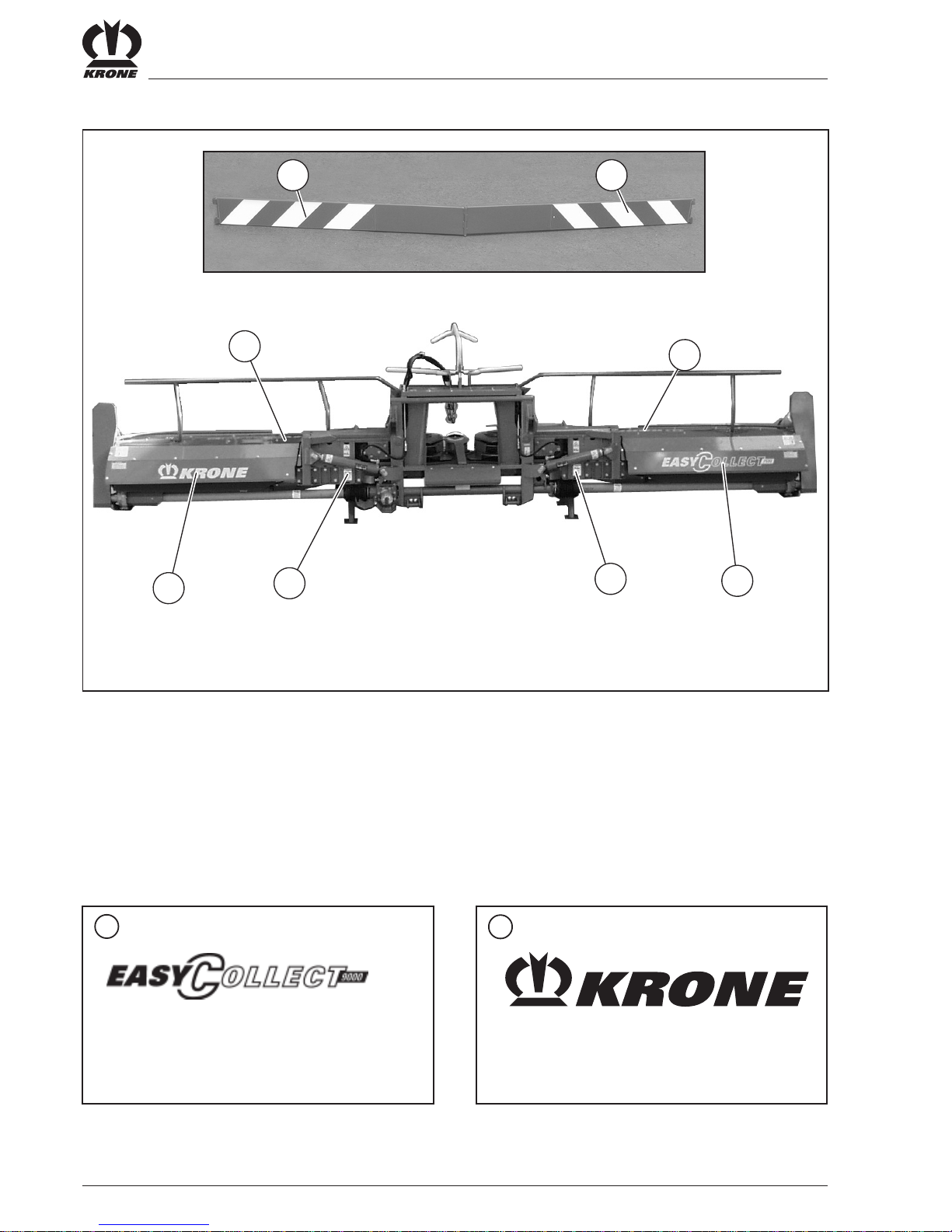
2.3.2 Location of the general warning signs on the machine
1
EASYCOLLECT 6000 Order No. 942 437-0
EASYCOLLECT 7500 Order No. 942 414-0
EASYCOLLECT 9000 Order No. 942 415-0
2
EASYCOLLECT 6000 Order No. 942 301-0
EASYCOLLECT 7500/9000 Order No. 942 341-1

II - 9
Safety
3
Order No. 942 301-0 (7500/6000)
Order No. 942 320-0 (9000) (2x)
5
Order No. 942 440-0 (2x)
4
EASYCOLLECT 6000 Order No. 942 437-0
EASYCOLLECT 7500 Order No. 942 438-0
EASYCOLLECT 9000 Order No. 942 439-0 (2x)
6
Fully reflecting adhesive
strips Order No. 924 625-0
Order No. 924 626-0

II - 10
Safety

III - 1
Start-up
3 Start-up
3.1 Special safety instructions
The maize header must only be
attached to the forage harvester for
which it is intended.
No one is permitted in the hazardous
area of the machine during
operation.
The protective equipment on the
maize header protects against access
to hazardous areas. Because of this,
you must always move them to their
protective position before starting
week.
Do not open or remove the protective
equipment when the engine is
running
No one is permitted in the rotation
area when the maize header is
swinging away from the transport into
the working position or vice versa.
Special caution is required when
mounting and detaching the maize
header on and from the forage
harvester. The accident prevention
regulations must be complied with
absolutely.
On public roads and paths, the
EASYCOLLECT 6000 and
EASYCOLLECT 7500 maize header
must always be in the transport
position.
In this case the transport height must
be set so that the max. permissible
height of 4 m is not exceeded.
The EASYCOLLECT 9000 maize
header must be placed on a special
transport carriage for road transport.
3.2 Stop points
Use only transportation equipment of
suitable dimensions (crane, ropes)!
• For transporting from one place to another onsite,
(moving) brace the lifting tool against the points
illustrated here.
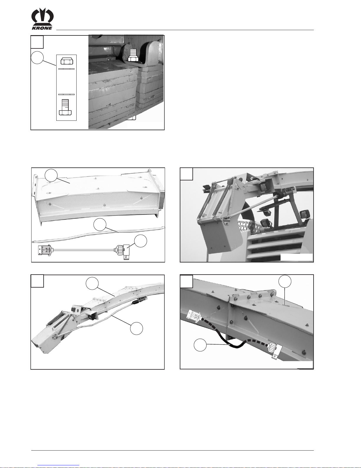
3.3 Storage
• Set the maize header (1) down with the parking
supports (2) extended on a solid and level surface
and park it in a dry and clean place.
Danger of accident and damage!
Place hydraulic hoses and electrical
connection cable (3) on the maize
header (1).
EC200011
1
3
2
EC200070
III - 2
Start-up
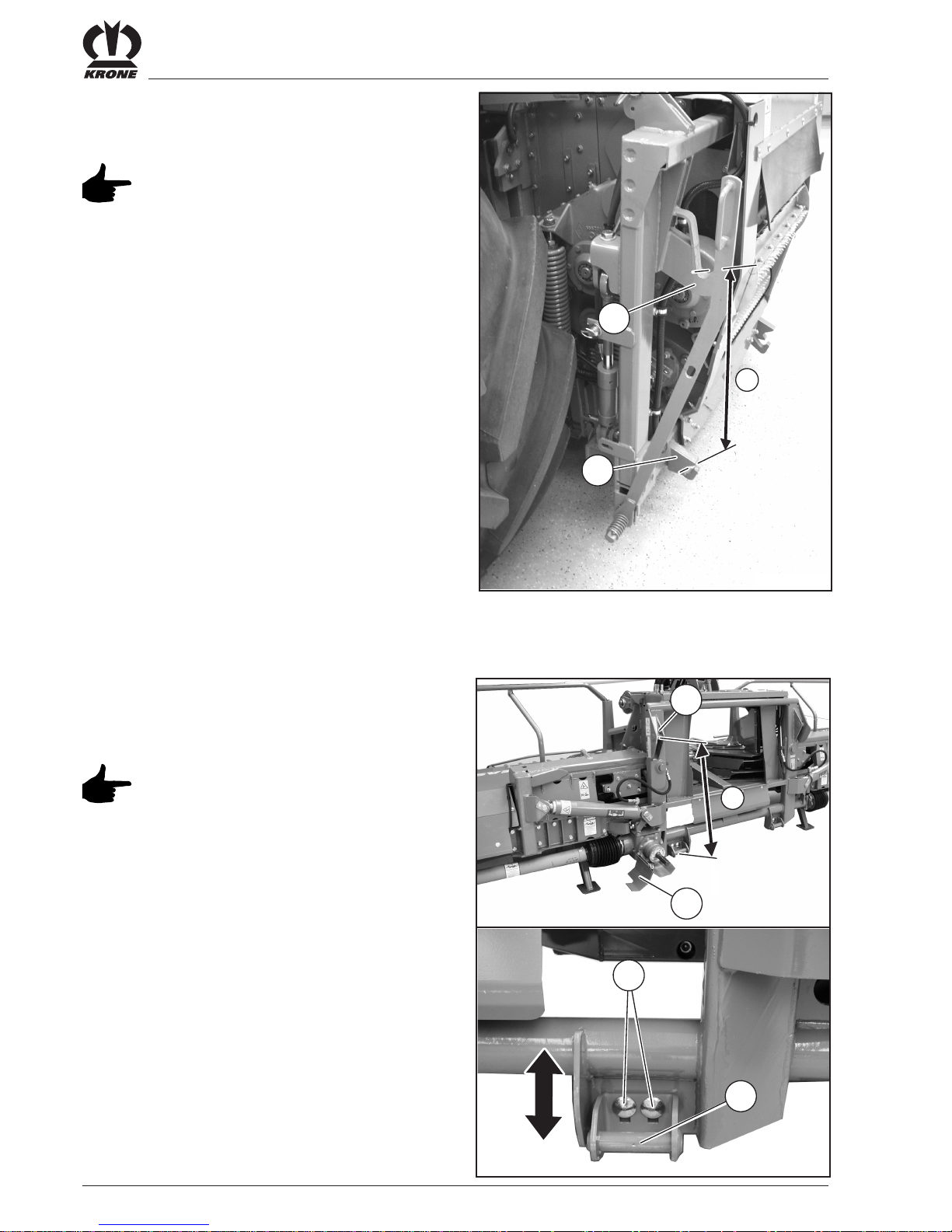
3.4 Attaching
3.4.1 Adjusting the adapter frame
Only when the forage harvester is
initially attached or replaced.
• Measure the axle base „a“ between holding claw (1)
and locking hook (2) on the pendulum frame of the
forage harvester.
1
2
3
a
EC200090
4
1
2
EC200080
a
• Check the axle base „a“ between the holding bolt
(1, 3) of the adapter frame on the maize header and
if necessary adapt it to the size of the pendulum
frame.
Make the adjustment equally on the
right and left of the adapter frame.
• Loosen the screw connections (2) and shift the
pendulum frame holders (3) to the correct distance.
• Tighten the screw connections (2).
• Before driving the forage harvester into position,
fold down the protective cover (4).
III - 3
Start-up
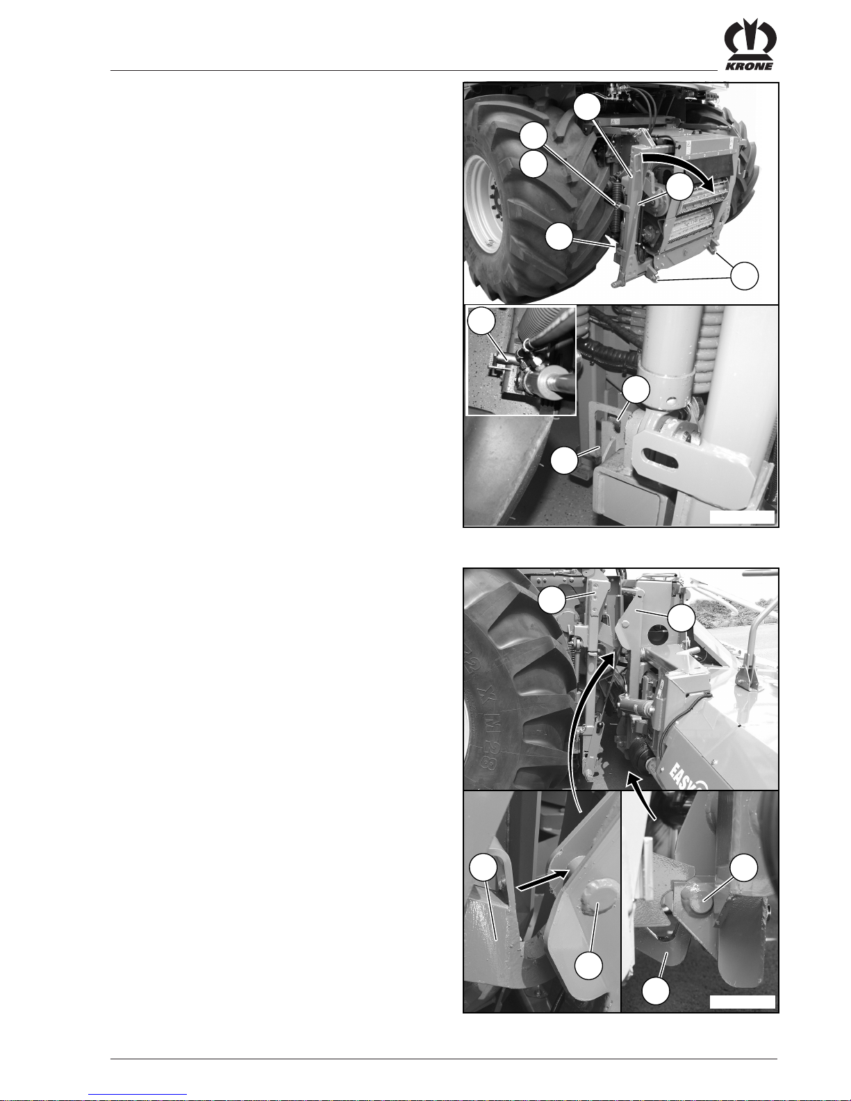
3.4.2 Pendulum frame
• Lower the pendulum frame (1) of the forage harvester
all the way.
• Align the pendulum frame (1) of the forage harvester
horizontally.
• Locking hooks (2) must be opened. If necessary,
open them with the locking lever (3).
• Disconnect the spring-loaded plug (5), pull the
locking lever (3) from the locking pin (4) and swing it
forward.
• The pendulum frame (1) must be unlocked and the
locking pin (6) must be in position II (unlocked).
3.4.3 Coupling
• Drive the forage harvester up to the maize header so
that the pendulum frame (1) stands just in front of
the adapter frame (2) and the holding bolts (4) are
located against the stop surfaces of the holding
claws (3).
• Raise the pendulum frame (1) with lifting hydraulics
until the locking hooks (5) lie in the pendulum frame
holder (6) on the adapter frame.
• Stop the machine.
1
2
3
I
EC200081
6
II
4
5
6
2
1
4
5
6
3
EC100120

III - 4
Start-up
The system should be without
pressure on both sides when
connecting the hydraulic hoses.
Make sure the plugs and couplings
are clean; clean them if necessary.
• Connect the hydraulic hoses (1) to the plug-in
connections provided for this purpose on the forage
harvester.
• Connect the lighting cable (2) to the socket.
• Connect the connection cable (3) of the sensors.
• Swing the locking lever (2) to the rear and engage it
on the locking pin (3) with spring plug (4).
Check that the pendulum frame hooks
correctly into the holding bolts (1) and
the locking hooks on both sides.
• Push the joint fork (1) onto the drive journal (2) of the
main angular gear until the closure engages.
For additional settings to operate the
maize header, see the operating
instruction „Self-propelled forage
harvester BiG X“.
• Close the cover guard (3).
3
2
EC200170
1
1
2
EC200160
3
2
3
4
EC200150
1

III - 5
Start-up
3.5 Transport position
Before folding the maize header into
its transporting position, turn off the
drive.
The maize header may be folded in
only with complete standstill of the
drive.
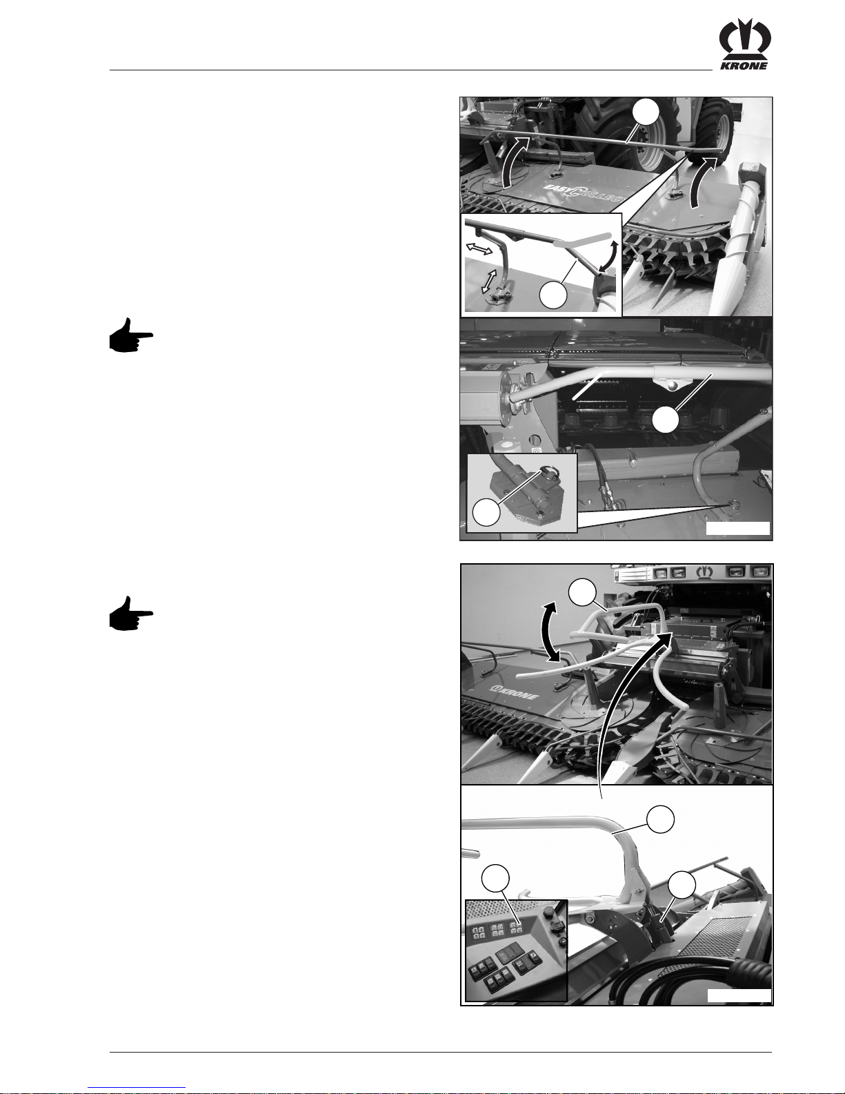
3.5.1 Folding in the tubular bar on the
right/left
Transport must only be performed
with the right/left tubular bars folded
inward.
• Pull off the linch pins (2) on both holders and fold
the tubular arm (1) over to the inside.
1
EC200180
1
2
2
• Push the middle tubular bar (3) before folding the
side parts in until it no longer protrudes beyond the
central part (4).
EC200570
4
3

III - 6
Start-up
3.5.2 Swinging the maize header up
• Swing the maize header (1) up completely with the
forage harvester hydraulics until the latch (2) snaps
into place.
• Check that the outriggers are locked on both sides
in the latches (2).
1
2
EC200200

III - 7
Start-up
3.5.4 Installing guard on the right/left
• Push the guard (1) on the right and left onto the tips.
• Fasten protective cloths (1) with tension springs (2)
to the frame.
3.5.5 Connecting indicators and position
lights on the right/left
• Connect connection cables (2) of the indicators and
position lights (1) in the relevant socket (3) on both
sides of the maize header.
• Check the lighting for function.
3.5.3 Parking supports in transport
position on the right/left
• Stop the machine.
• Remove the spring cotter pins (2) and push in
parking supports (1) .
• Secure position with spring cotter pin (2).
1
1
1
2
EC200230
1
2
3
EC200250
1
2
EC200220

III - 8
Start-up
3.5.6 Installing the front guard
• Fit the front guard (1) on the right and left onto the
holder on the support and centrally on the central
tip, pay attention to the prescribed position of the
warning stripes (2) (the hatching must point
downwards and outwards).
• Secure front guard (1) on the right and lift with spring
cotter pins (3) and hook tension springs (4) on the
central tip.
3.5.7 Road travel
When driving on roads, the general
requirements or special conditions of
the Road Traffic Type Approval Law
(StVZO) and the Road Traffic Law
(StVO) must be observed.
In the case of self-propelled working
machines the harvesting attachments
must be included in the operating
permission of the working machine (if
necessary extend the operating
permission). The conditions of the
operating permission must be
complied with.
The driving speed of the forage
harvester has to be adapted to the
local conditions.
3.6 Working position
3.6.1 Removing the protective cover
• Stop the machine.
• Remove the front guard (1).
• Pull off the lighting cables and remove the guards (2)
on the right and left.
3.6.2 Adjusting skids
The position of the skids (1)
determines the min. stubble length.
• Loosed the screw connections (2) and fasten the
skid (1) on the wanted position on the bearing plate
(3).
Adjust all skids equally.
1
2
3
3
4
EC200260
1
2
2
EC200270
1
2
3
EC200280
III - 9
Start-up
3.6.3 Folding up the tubular bar on the
right/left
• Swing the maize header into the working position
with the forage harvester hydraulics.
• Stop the machine.
• Pull off the linch pins (2) on both holders and fold
the tubular arm (1) up to the outside.
• Secure the working position of the tubular bar (1)
with linch pins (2).
3.6.4 Adjusting the plant dividers
Adjust the plant divider (1) to the
height of the crop in question so that
the plants are guided by the tubular
bars in the upper plant area when
being drawn into the cutting unit.
• The height of the plant divider (1) can be adjusted
with hydraulic cylinders (2) by pressing the
activation keys (3).
1
2
1
EC200290
3
The length of the tubular bar (3)
must be adjusted to match the crop
to be harvested
1
2
1
EC200181
3

III - 10
Start-up
Work on the maize header must only
be performed when the engine is
stopped and turned off and the
ignition key has been removed. All
operating levers must be in the
neutral setting and no hydraulic lines
may be under pressure.
Check the maize header each time
before it is used and after it has been
driven to make certain there are no
impediments.
Worn, used or deformed blades must
be replaced immediately.
The same applies for all fastening
parts.
Do not turn on the drive until the
maize header is in the working
position.
3.7 Using the machine for work
3.7.1 Special safety instructions
Keep persons out of the hazardous
area. If persons do approach the
hazardous area, please turn off the
machine immediately.
Never allow the machine to run
unsupervised.
Check the safety devices each time
before the machine is used. Replace
damaged safety devices immediately.
3.7.2 Using the maize header
• Move the maize header to the working position and
lower it down to the ground or to the wanted cutting
height..
• Turn on the maize header drive and adjust it to
working speed.
• Drive into the crop material with the forage harvester.
• The driving and collector speed should be based on
the conditions of usage at hand (ground conditions,
the height and nature of the crop, etc.).
The collector speed must not be
higher than the speed of drawing the
crop into the cutting unit.
It must be set so high that a clean cut
of the crop is guaranteed.
The travelling speed is based
primarily on the throughput of the
forage harvester.
3.7.3 Lifting gear spacing control
(optional)
The lifting gear spacing control is
available only if spacing sensors (1)
have been fitted.
When the lifting gear spacing control
is active, the control of the forage
harvester sets the height constant
relative to the ground (ground
copying).
1
EC100620
III - 11
Start-up
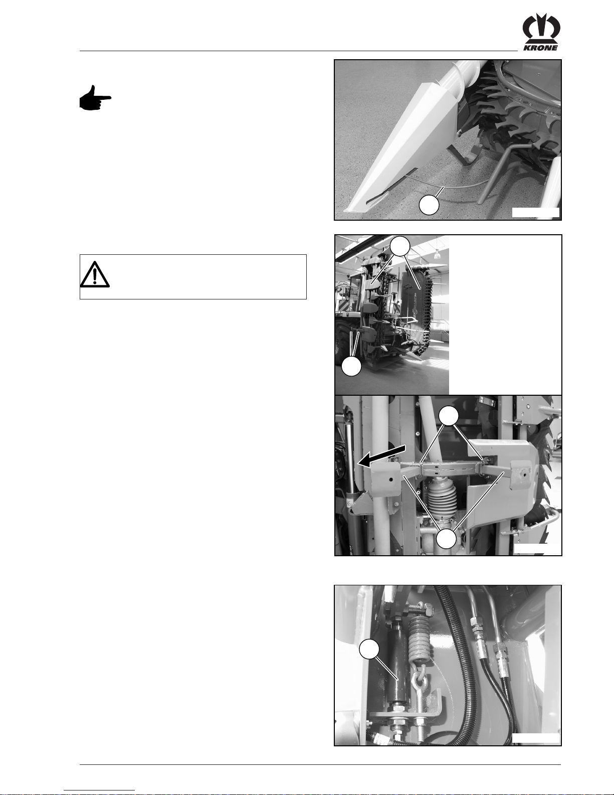
3.8 Detaching
Set the maize header down only on
solid and level ground and only with
the parking supports extended.
• Remove the spring cotter pins (3) and extend the
parking supports (2) .
• Secure position with spring cotter pins (3).
• Swing the maize header (1) with the forage harvester
hydraulics into the working position and let it down
on the ground.
• Move in the locking cylinder (1) with the forage
harvester hydraulics (Activation keys for folding in
the maize header).
• Stop the machine.
3.7.4 Autopilot (optional)
The autopilot function is available
only if sensors (1) and autopilot
equipment have been fitted.
The automatic pilot guides the forage
harvester along the maize row with
the sensors on the maize header.
1
EC100630
2
3
1
EC200201
2
1
EC100310

III - 12
Start-up
The system should be without
pressure on both sides when
disconnecting the hydraulic hoses (1).
• Disconnect the hydraulic lines (1) at the hydraulic
couplings and close off with dust caps.
• Pull off the lighting cable (2).
• Loosen the connection cable (3) of the sensors.
Danger of accident and damage!
Place hydraulic hoses and electrical
connection cable on the maize header.
• Open the protective cover (3).
.
• Pull the joint fork (1) off of the drive journal (2) of the
main angular gear.
• Open the locking hook (1):
Remove the spring cotter pin (3), pull the locking
lever (2) from the locking pin (4) and swing it
forward.
• Lower the pendulum frame of the forage harvester
until the receiving claws are below the holding bolts.
• Move the forage harvester back.
3
2
EC200170
1
1
2
EC200160
3
2
3
4
EC200151
1
IV - 1
Maintenance
4 Maintenance
4.1 Special safety instructions
Repair , maintenance and cleaning
tasks must only be performed while the
engine is stopped!
Remove the ignition key and secure the
forage harvester from being placed in
operation or rolling away
unintentionally.
For repair , maintenance and cleaning
jobs on a raised maize header always
secure it with suitable supporting
pieces and close the shut-off valve!
4.2 General aspects
• Test nuts and screws regularly (about every 50
hours) for firm seat and tighten according to the
tightening torque tables if necessary! Deviating
tightening torques are indicated separately in the
text.
Self-locking nuts must always be
replaced.
Tightening torque M
A
Only perform tasks on the hydraulic
system when all excess pressure has
been released.
Liquid escaping under high pressure
can penetrate through the skin and
cause severe injuries. In the event of
injuries, find a physician immediately .
There is danger of infection.
After all rep air, maintenance and
cleaning tasks are complete, all
protective coverings and safety mechanisms must be put in place again.
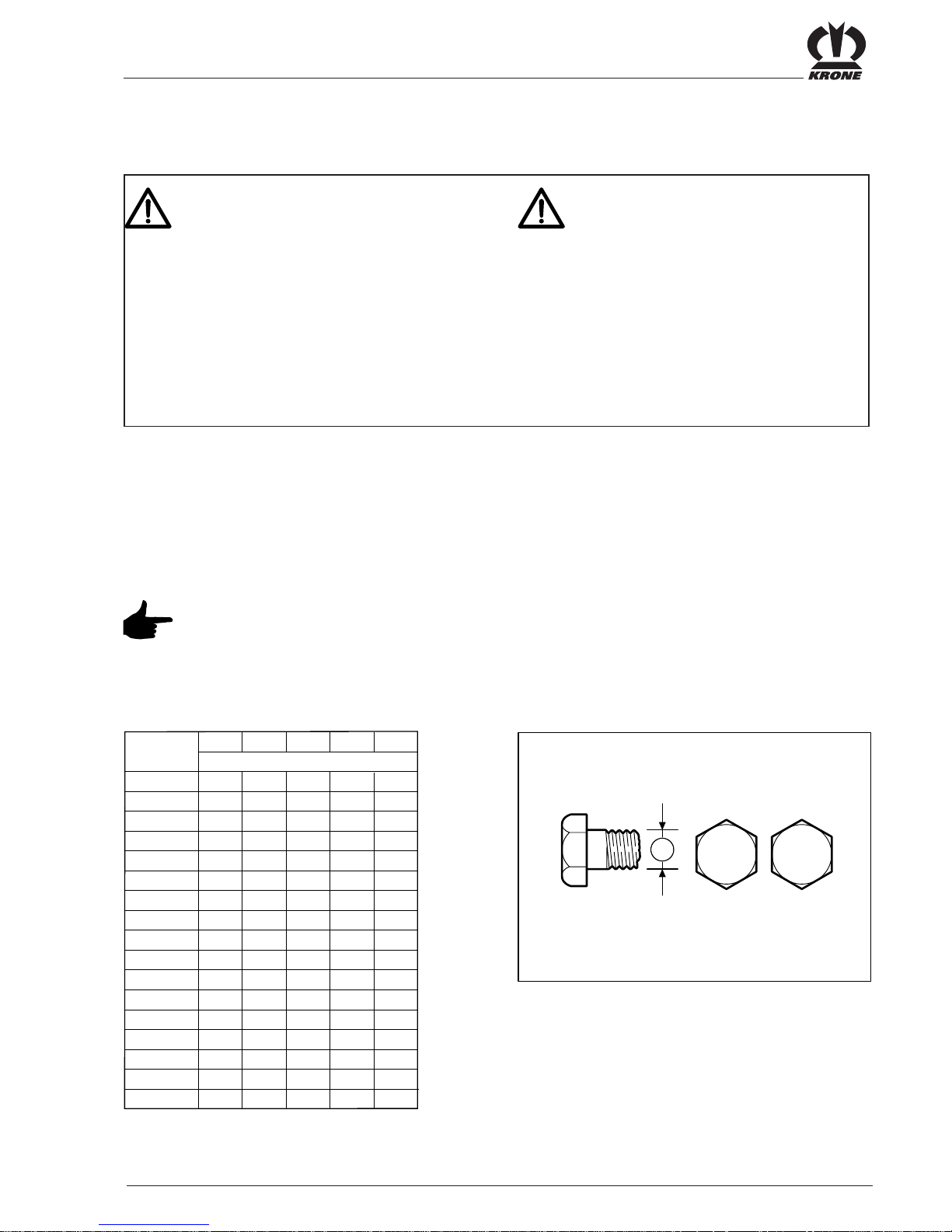
A = thread size
(stability class can be seen on the head of the screw).
A
5.6
29
42
2,2
4,5
7,6
18
37
64
100
160
4,4
8,7
15
36
72
125
200
215
310
1050
330
350
M 4
M 5
M 6
M 8
M 10
M 12
M 14
M 14x1,5
M 16
M 16x1,5
M 20
M 24
6.8
M (Nm)
8.8 10.9
A
O
/
12.9
M 24x1,5
M 24x2
M 27
M 27x2
M 30
5,1
10
18
43
84
145
235
255
365
2450
390
3,0
5,9
10
25
49
85
135
145
210
225
730
710
1220
1350
1800
1950
2100
1150
1550
1650
1450
800
1100
1150
610
425
8
.
8
1
0
.
9
A
BP380-7-073
IV - 2
Maintenance
4.2.1 Tightening torques on the
aluminium gears
EC100660
72 Nm
9 Nm
17 Nm
210 Nm
210 Nm
49 Nm
EC100662
49 Nm
85 Nm
72 Nm
72 Nm
72 Nm
80 Nm
EC100661
17 Nm
72 Nm
30 Nm
72 Nm
9 Nm
49 Nm
EC100663

IV - 3
Maintenance
4.3 Gearboxes
• If no other instructions are given, change the oil
once a year on all gears.
• Check the oil level before the beginning of the season.
• Check all gears daily for any leaks and check the
oil level if necessary.
4.3.1 Lubricant quantities and
designations for gearboxes
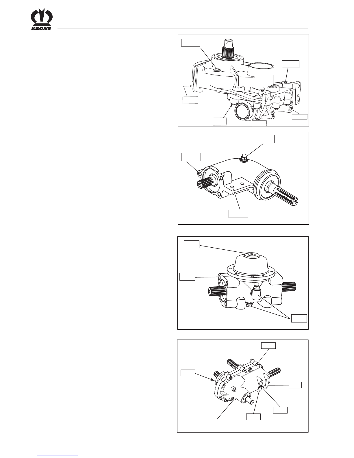
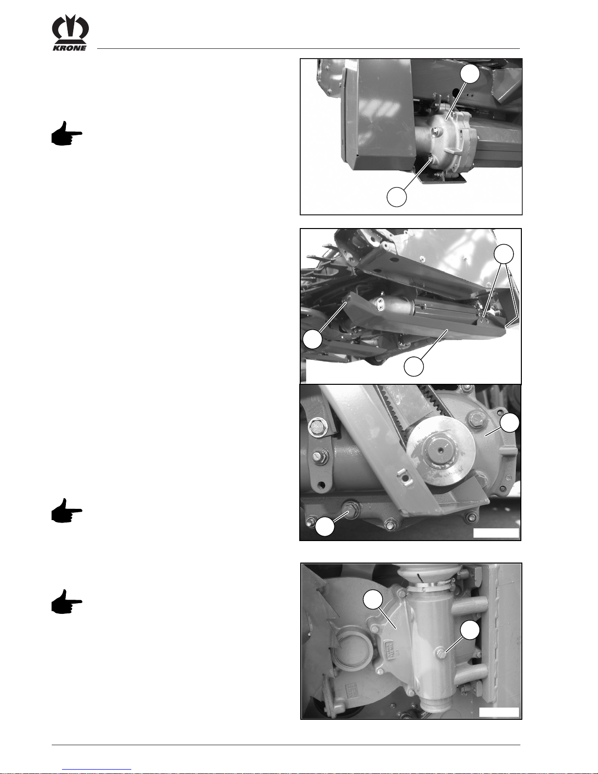
4.3.2 Checking the oil level and changing
the oil in the main angular gearbox
Check the oil level and change the oil
while the maize header is in a
horizontal position!
Checking the oil level
• Unscrew the oil level monitoring screw (2) on the
main angular gearbox (1).
• The oil level must reach up to the monitoring drill
hole. If necessary, add more oil through the
monitoring drill hole.
• Screw in the oil level monitoring screw (2) again.
Changing the oil
• Unscrew the oil drain screw (3) on the main angular
gearbox (1). Capture the oil in a suitable container.
• Screw on the oil drain screw (3) again.
• Unscrew the oil level monitoring screw (2) on the
main angular gearbox (1).
• Add oil (for filling quantity and type of oil, see
Chapter 4.3.1)
• Screw in the oil level monitoring screw (2) again.
Dispose of old oil properly.
1
2
1
3
EC200320
Filling quantities (litres) Type of oil Bio-degradable lubricants
Main angular gearbox 1,9
Transfer gearbox 0,35
Collector gearbox 4,2
Angular gearbox 0,2 on request
Dresser gearbox 0,14
SAE 90 GL 4 or
Esso-Spartan EP 150
Shell Omala Oil 150
Fuchs - EP 85 W90
Castrol EPX 90
IV - 4
Maintenance
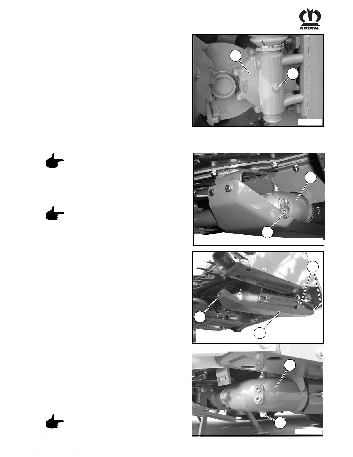
4.3.3 Checking the oil level and changing
the oil in the transfer gearbox (right/
left)
Perform oil level checks and oil change
while the maize header is in its working
position!
Checking the oil level
• Unscrew the oil level control screw (2) on the
transfer gearbox (1).
• The oil level must reach up to the control hole. If
necessary, add more oil through the control hole .
• Screw in the oil level control screw (2) again.
Changing the oil
• Remove the gear skid (4) by loosening the screws
(5).
• Unscrew the oil drain screw (3) on the transfer
gearbox (1). Collect the oil in a suitable container .
• Screw on the oil drain screw (3) again.
• Unscrew the oil level control scre w (2) on the
transfer gearbo x (1).
• Add oil (for filling quantity and type of oil, see
Chapter 4.3.1)
• Screw in the oil level control screw (2) again.
• Mount the gear skid (4).
Dispose of old oil properly.
4.3.4 Checking the oil level and changing
the oil in the collector gearbox
(right/left)
Check the oil level in the horizontal
position of the maize header in
transport position!
Checking the oil level
• Unscrew the oil level control scre w (2) on the collector gearbox (1).
• The oil level must reach up to the control hole. If
necessary, add more oil through the control hole .
• Screw in the oil level control scre w (2) again.
1
2
EC07600
5
5
3
EC200340
4
1
2
1
EC200345
IV - 5
Maintenance
Changing the oil
• Swing the maize header into its working position.
• Unscrew the oil level control screw (2) on the
collector gearbox (1) . Collect the oil in a suitable
container.
• Screw in the oil level control screw (2) again.
• Swing the maize header into its transport position.
• Unscrew the oil level control screw (2) on the
collector gearbox (1).
• Add oil (for filling quantity and type of oil, see
Chapter 4.3.1)
• Screw in the oil level control screw (2) again.
Dispose of old oil properly .
4.3.5 Checking the oil level and changing
the oil in the angular gearbox (right/
left)
Perform oil level checks and oil
changes while the maize header is
horizontal in it s working position!
Checking the oil level
• Unscrew the oil level control screw (2) on the
angular gearbox (1).
• The oil level must reach up to the control hole. If
necessary, add more oil through the control hole .
• Screw in the oil level control screw (2) again.
Changing the oil
• Getriebekufe (4) durch Lösen der Schraubverbindungen (5) demontieren.
• Unscrew the oil drain screw (3) on the angular
gearbox (1). Collect the oil in a suitable container .
• Screw on the oil drain screw (3) again.
• Unscrew the oil level control screw (2) on the
angular gearbox (1)
• Add oil (for filling quantity and type of oil, see
Chapter 4.3.1)
• Screw in the oil level control screw (2) again.
• Mount the gear skid (4).
Dispose of old oil properly.
1
2
EC07600
1
3
5
5
EC200360
4
1
2
EC200365

IV - 6
Maintenance
4.3.6 Checking the oil level and changing
the oil in the dresser gearbox (right/
left)
Check the oil level in the horizontal
position of the maize header in
transport position!
Checking the oil level
• Unscrew the oil level control scre w (2) on the
dresser gearbox (1).
• The oil level must reach up to the control hole. If
necessary, add more oil through the control hole .
• Screw in the oil level control scre w (2) again.
Changing the oil
• Swing the maize header into its working position.
• Unscrew the oil level control scre w (2) on the
dresser gearbox (1). Collect the oil in a suitable
container.
• Screw in the oil level control screw (2) again.
• Swing the maize header into its transport position.
• Unscrew the oil level control scre w (2) on the
dresser gearbox (1).
• Add oil (for filling quantity and type of oil, see
Chapter 4.3.1)
• Screw in the oil level control scre w (2) again.
Dispose of old oil properly .
1
2
EC100370

IV - 7
Maintenance
4. 4 Laid maize worm drive belt
(right / left)
4.4.1 Checking the drive belt tension
Check the drive belt tension after the
first 10 operating hours, then every 60
operating hours.
• Unscrew the hexagon head screws (2) and remove
the protective plate (1).
• Check the drive belt (1) for cracks or other damage,
if necessary renew the drive belt.
Always change the drive belts in p airs.
• Check the drive belt (3) tension in the middle by
pressing in (pressing force about 50 N). If the depth
of pressing in is a = approx 20 mm, the tension of
the drive belt is correct, if necessary correct it.
4.4.2 Correcting the drive belt tension
• Loosen the mounting screws (1) a little.
• Loosen the counter nut (2) and correct the
pretension by turning the nut (3).
• Check the tension of the drive belt, if necessary
repeat the process.
• Tighten the counter nut (2) and mounting screws
(1).
• Fit the guard.
3
EC100390
a
1
1
3
2
EC100400
1
2
2
EC200380

IV - 8
Maintenance
4. 5 Collector pre-tension (right /
left)
4.5.1 Checking the collector pre-tension
Check the collector pre-tension after
the first 10 operating hours, then every
60 operating hours.
• The compression spring (1) is correctly pre-
tensioned if the dimension is “a = 325 - 330” mm. If
necessary correct the collector pre-tension.
4.5.2 Correcting the collector pre-tension
• Loosen the counter nut (2) and correct the
pretension of the compression spring (1) by turning
the hexagonal nut (3).
• Check the dimension “a” again, if necessary repeat
the process.
• Tighten the counter nut (2).
a
3
EC100410
1
2
3
EC100411
IV - 9
Maintenance
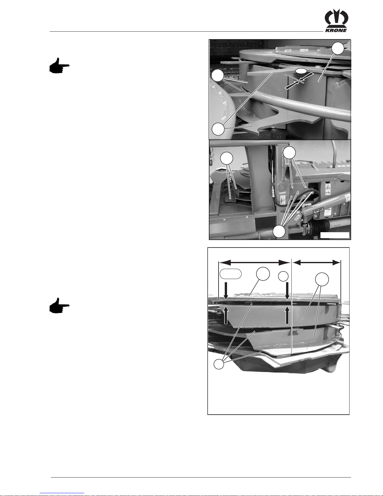
4. 6 Scraper (right / left)
The distance between the back of the
collector (2) and the scraper (1) must
not exceed the dimension «a = 3 mm».
4.6.1 Adjusting the scraper
• Loosen the screws (3) a little and press the scraper
(1) against the back of the collector (2). Distance
“a = 1 - 3 mm”.
EC100664
X
y
a+4
a
b
1
5
Setting of the gaps (b):
• The scrapers (1) must be aligned parallel to the
collector fingers (4) in the area marked «X». The
scrapers (1) must be extended back conically in the
area marked «Y» (a+4)
If necessary, align the cover (5) as well
by loosening the screws (6).
2
3
EC200420
a
1
1
4
6
• Tighten the screw connections (3).

IV - 10
Maintenance
4.7 Tips
The lower edges of the side tips (1
right/ 1 left) should be at the same
height as the lower edges of the tips
(2). The lower edges of the central
tip (3) should be about x = 30-50
mm lower than the lower edges of
the other tips (a = freely selectable
distance to the ground).
If necessary correct the height
adjustment of the side or central
tips.
4.7.1 Adjusting the side tips (right / left)
• Loosen the screws (2) a little.
• Shift the adjusting plate (3) until the bottom edge of
the side tip (1) is at the height of the bottom edges
of the tips.
• Tighten the screw connections (2).
4.7.2 Adjusting the central tip
• Loosen the screws (2) a little.
• Adjust the central tip (1) so that the bottom edge is
approx. x = 30-50 mm below the bottom edges of
the tips.
• Tighten the screw connections (2).
4.7.3 Replacing tips
• Unscrew the cheese head screws (2) on both sides
of the tip (1) and remove the tip (1).
• Remove the bearing rings (3) from the tip (1) and
insert them in the new tip.
• Fit the new tip (1) with the cheese head screws (2).
1
2
3
EC200430
a
a-x
a
2
EC200440
1
1
2
3
EC200450
1
EC200460
2
3
IV - 11
Maintenance
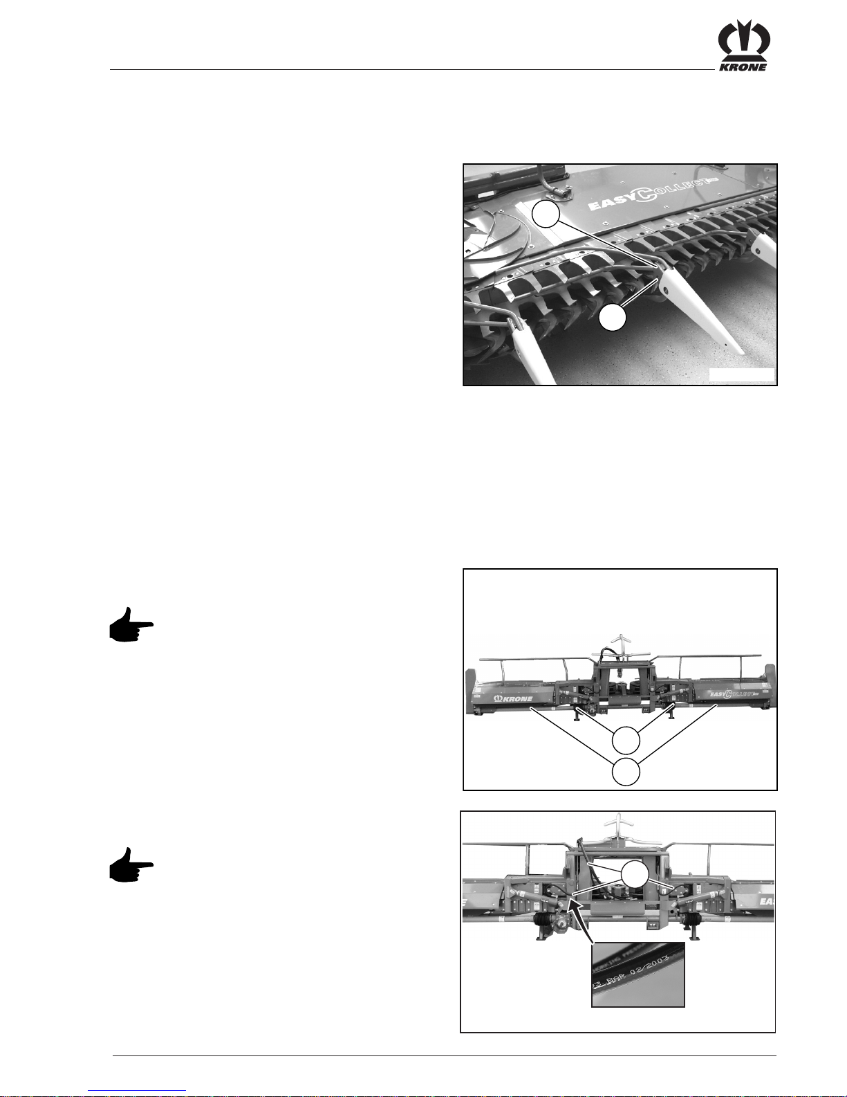
4.9 Installing PTO shafts
T ake care in the installation of the PTO
shafts (1) that the cross joints (2) are
fitted parallel to one another.
4.10Hydraulic hose lines
Hydraulic hose lines may be used for 6
years at the most after manufacture.
The date of manufacture (month/year)
is stated on the hydraulic hose line.
• Check all hydraulic hose lines regularly and replace
them if they are damaged or show signs of ageing.
Replacement hose lines must meet the technical
requirements of the device manufacturer!
!
EC200490
1
EC200465
2
1
2
EC200025
4.8 Removing the upper insert
finger
• Removing the upper insert finger

IV - 12
Maintenance
4.11Changing blades
Wear protective gloves when working
on the blades!
Check the blades each time before
using them and each time after driving
for obstacles.
Worn, damaged or deformed blades
must be replaced immediately .
4.11.1 Changing bow and step blades
When replacing observe the left/right
cutting direction!
• Unscrew the hexagon head screws (2) and pull off
the bow blade, inside (1) to the front.
• Insert a new bow blade (1) and fasten it with the
hexagon head screws (2).
• Unscrew the hexagon head screws (2) and pull off
the bow blade, outside (1) to the front.
• Insert a new bow blade (1) and fasten it with the
hexagon head screws (2).
• Unscrew the 2 hexagon head screws (4) and pull off
the step blade, inside (3) to the front.
• Insert a new step blade (3) and fasten it with the 2
hexagon head screws (4).
After replacement of the blades make
sure that no abutting edges arise.
If necessary use shims or grind off
projecting edges.
1
2
2
EC200520
1
2
EC200530
3
4
EC100510
IV - 13
Maintenance
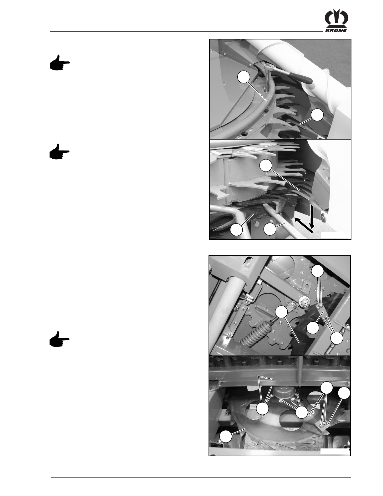
4.11.2 Changing cutting blades
When replacing observe the cutting
direction right/left and the number of
blades 1 or 2!
• To remove the cutting blades (1) (only possible
outside in the area of the bow) unscrew the internal
hexagon head screw (2).
• Push up the collector on the step blade (4) with tyre
lever (3) and first pull the cutting blade down (1) off
the cam and then remove it to the rear.
• Tightening torque of the hexagonal
screw (2) = 85 Nm (8.8)
• Tightening torque of the hexagonal
screw (2) = 110 Nm (10.9)
• Use a high-strength screw locking
agent (for example Loctite).
• Installation of the new cutting blade (1) in the
reverse order of remov al.
4.11.3 Changing dresser segments (right /
left)
• Release the tension on the connectors (3, 4) on
both sides of the dresser segment (1) by loosening
the screws (2).
• Unscrew the hexagon head screws with the locking
washers (5) and remove the dresser segments (1).
On assembly observe the tooth
direction of the dresser segments!
Renew the self-locking nuts of the
screw connections (2)!
Absolutely comply with the position of
the carriage bolts (2) and connectors
(3, 4)!
• Installation of the new dresser segments (1) in the
reverse order of remov al.
1
2
2
3
4
5
5
2
1
EC200560
1
1
3
4
EC200540
2

IV - 14
Maintenance
4.11.4 Changing scraper blades (right /
left)
• Unscrew the 2 hexagon head screws (2) and
remove the scraper blade (1).
• Installation of the new scraper blade (1) in the
reverse order of remov al, take care that the cutting
edge lies against the collector .
1
2
EC100580

IV - 15
Maintenance
4.12Lubrication
4.12.1 PTO shafts
• All PTO shafts have to be lubricated after 250
operating hours in keeping with the data in the
operating instructions of the manufacturer of the
PTO shaft.
EC200024
100 h
250 h
25 h

IV - 16
Maintenance
4.12.2 Lubrication chart
• The lubricating points mentioned below must be
lubricated after the operating hours indicated.
EC200023
250
h
250
h
25
h
25
h
250
h
250
h
25
h
25
h
optional

IV - 17
Maintenance
4.13Storing when not in use
• Clean the machine thoroughly inside and out. Dirt
attracts moisture, which leads to the formation of
rust. When cleaning with high-pressure washing
devices, do not point the stream of water at the
bearing.
• Check movable parts (joints, etc.) to make certain
they move easily. If necessary, dismount them,
clean them and check them for wear. If necessary,
replace with new parts!
• Oil all joint points!
• Lubricate the machine thoroughly.
• Grease the protective tubes of the PTO shafts to
prevent freezing up .
• Repair places with worn paint and preserve all bear
metal places thoroughly with rust protection agent.
• Park the machine in a dry place. Do not store it in
the vicinity of artificial fertilisers.
• List all required spare parts and order them in good
time. It is easier for your KRONE dealer to provide
and install the required parts outside the season.
Then the machine will be completely ready for use
the coming season.
EC200026

IV - 18
Maintenance

I - 1
Anhang
A1 Commissioning
• Repair, maintenance and cleaning tasks must only be performed while the engine is stopped!
Remove the ignition key and secure the forage harvester from being placed in operation or
rolling away unintentionally.
• After completing maintenance work reattach all protective devices properly. Avoid skin contact
with oil and grease. Contact a doctor immediately if injuries are caused by escap-ing oil.
• Use only suitable and approved tools to assemble and disassemble the parts.
A1.1Fitting the additional weights
1
2
3
4 5
EC100667
a
b
EC100668
a
1
EC100669
3
a
EC100670
b
2
EC100671
b
4
EC100672
I - 2
Anhang
b
5
EC100673
A1.2Fitting the discharge extension (only for EasyCollect 7500;
EasyCollect 9000)
1
2
3
EC100674
a
EC100675
b
EC100676
1
2
c
3
EC100677
1

I - 3
Anhang

Maschinenfabrik
Bernard Krone GmbH
Heinrich-Krone-Straße 10, D-48480 Spelle
Postfach 11 63, D-48478 Spelle
Phone +049 (0) 59 77/935-0
Fax +049 (0) 59 77/935-339
Internet: http://www.krone.de
eMail: info.ldm@krone.de
. . . konsequent, kompetent
12-Jan-2006
 Loading...