

Krone Big Pack 890, Big Pack 1290, Big Pack 1270, Big Pack 1290 HDP, Big Pack 1290XC Operating Instructions Manual
...
Operating Instructions
150 000 050 01 EN
Big Pack Baler
Big Pack 890/XC
Big Pack 1270/XC/MultiBale
Big Pack 1290/XC
Big Pack 1290 HDP / XC (Machine No. 721 564 or higher)

Dear Customer:
These are the operating instructions for the KRONE product that you
have purchased.
These operating instructions contain important information for the
correct use and safe operation of the machine.
Should these operating instructions have become unusable completely
or partially for any reason, you can obtain replacement operating
instructions for your machine by stating the number quoted on the
reverse.
We
declare in our sole responsibility that the product
to which this declaration refers corresponds to the relevant basic safety and health requirements of the
EC Directive 98/37/EC.
EC Declaration of Conformity
corresponding to the EC Directive 98/37/EC
Maschinenfabrik Bernard Krone GmbH
Heinrich-Krone-Str. 10, D-48480 Spelle, Germany
Krone Big Pack Baler
Types: Big Pack 890; Big Pack 1270; Big Pack 1290
Big Pack 890 XC; Big Pack 1270XC; Big Pack 1290XC
Big Pack 1290 HDP; Big Pack 1290 HDP XC
Spelle, 10.042007
(Dr.-Ing. Josef Horstmann, Managing Director)
(ppa. Dr.-Ing. Klaus Martensen, Director of Design and Development)

1
Contents
Contents
1 General Information ........................................................................... I -1
1.1 Purpose .................................................................................................................. I -1
1.2 Intended Use .......................................................................................................... I -1
1.3 Information Required in Case of Questions and Orders ........................................ I -1
1.4 Technical Data........................................................................................................ I -2
1.4.1 Big Pack 890/XC .................................................................................................... I -2
1.4.2 Big Pack 1270/XC/MultiBale ................................................................................... I -3
1.4.3 Big Pack 1290/XC .................................................................................................. I -4
1.4.4 Big Pack 1290 HDP / XC ........................................................................................ I -5
1.4.5 Lubricants ............................................................................................................... I -6
1.5 Connection Requirements, Tractor ........................................................................ I -7
1.6 General Technical Description................................................................................ I -8
1.7 Overviews ............................................................................................................... I -9
1.7.1 Left Side of the Big Pack Baler with Tandem Axle ................................................. I -9
1.7.2 Right Side of the Big Pack Baler with Tandem Axle ............................................. I -10
1.7.3 How the VFS Conveyor System Works ................................................................ I -11
1.7.4 Functional Description of the Big Pack Baler ........................................................ I -12
2 Safety .................................................................................................. II -1
2.1 Identifying Symbols in the Operating Instructions .................................................. II -1
2.2 Safety Instructions and Accident Prevention Regulations ...................................... II -1
2.2.1 Personnel Qualification and Training ...................................................................... II -1
2.2.2 Dangers in case of Non-Compliance with the Safety Instructions .......................... II -1
2.2.3 Safety-Conscious Working ..................................................................................... II -1
2.2.4 Safety Instructions and Accident Prevention Regulations ...................................... II -2
2.2.5 Hitched Implements................................................................................................ II -3
2.2.6 PTO Operation ....................................................................................................... II -3
2.2.7 Hydraulic System.................................................................................................... II -3
2.2.8 Tyres ...................................................................................................................... II -4
2.2.9 Maintenance ........................................................................................................... II -4
2.2.10 Unauthorised Modifications and Spare Parts Production ....................................... II -4
2.2.11 Non-Permissible Modes of Operation..................................................................... II -4
2.3 Introduction ............................................................................................................ II -5
2.3.1 Location of Safety Stickers on the Machine ........................................................... II -5
2.4 Special Safety Instructions ..................................................................................... II -7
2.4.1 Ladder .................................................................................................................... II -7
2.4.2 Fire Extinguisher..................................................................................................... II -7
3. Start-up and Transport ..................................................................... III -1
3.1 Safety Instructions................................................................................................. III -1
3.2 General Operation ................................................................................................. III -1
3.2.1 Parking Support ..................................................................................................... III -1
3.2.2 Hydraulic Support Base (Optional) ........................................................................ III -2
3.2.3 Parking Brake ........................................................................................................ III -2
3.2.4 Holding Brake for Flywheel .................................................................................... III -3
3.2.5 Adjusting the Drawbar Height ................................................................................ III -3
3.3 Connecting to the Tractor...................................................................................... III -4

2
Contents
3.4 Main PTO Shaft..................................................................................................... III -4
3.4.1 Adapting the Main PTO Shaft................................................................................ III -4
3.4.2 Mounting on the tractor side ................................................................................. III -5
3.5 Hydraulic, Compressed Air and Electrical Connections......................................... III -6
3.5.1 Hydraulic Brake (country-specific) ......................................................................... III -6
3.5.2 Hydraulic Connection for Locking the Coaster Axle (Optional).............................. III -6
3.5.3 Load-Sensing Connection (optional) ..................................................................... III -7
3.5.4 Compressed Air Brake .......................................................................................... III -8
3.5.5 Holders for the Compressed Air Hoses ................................................................. III -8
3.5.6 Electrical Connection Cables ................................................................................. III -9
3.6 Placing in Operation again after an Extended Standstill Time............................. III -10
3.6.1 Safety Instructions............................................................................................... III -10
3.6.2 General Information ............................................................................................ III -10
3.6.3 Overload Coupling on the Flywheel ..................................................................... III -10
3.6.4 Storage for Winter ............................................................................................... III -11
3.7 Transport ............................................................................................................. III -12
3.7.1 Preparations for Road Travel .............................................................................. III -12
3.7.2 Moving ................................................................................................................. III -13
3.7.3 Coaster/Steering Axle (Optional) ......................................................................... III -14
3.7.3.1 Moving the machine without hydraulic connection .............................................. III -14
3.8 Parking the Big Pack Baler .................................................................................. III -15
4 Comfort Control Unit ........................................................................ IV -1
4.1 General Description ............................................................................................... IV -1
4.2 Mounting................................................................................................................ IV -2
4.3 Control Unit ........................................................................................................... IV -4
4.4 Operational Readiness .......................................................................................... IV -5
4.5 Manual Mode......................................................................................................... IV -6
4.5.1 Basic Screen for Manual Mode 1/2 .......................................................................IV -6
4.5.2 Basic Screen for Manual Mode 2/2 .......................................................................IV -8
4.6 Automatic Mode .................................................................................................. IV -13
4.7 Buttons on the Machine ...................................................................................... IV -14
4.8 Description of the Baling Process........................................................................ IV -15
4.8.1 Bale Channel is Empty ........................................................................................ IV -15
4.8.2 Bale Channel is Full ............................................................................................. IV -15
4.9 Menu Level .......................................................................................................... IV -16
4.9.1 Bringing up a Menu Level .................................................................................... IV -16
4.9.2 Main Menu 1 “Settings” ....................................................................................... IV -17
4.9.3 Menu 1-1 “Correction value for bale length” ........................................................ IV -18
4.9.4 Menu 1-2 “Knotter signal”.................................................................................... IV -19
4.9.5 Menu 1-3 “Sensitivity of direction display” ........................................................... IV -20
4.9.6 Menu 1-4 "Contrast" ............................................................................................ IV -21
4.9.7 Menu 1-5 “Central lubrication” ............................................................................. IV -22
4.9.8 Menu 1-6 "Knotter blowing" ................................................................................. IV -23
4.9.8.1 Menu 1-6-1 "Strokes / blow" ................................................................................ IV -24
4.9.8.2 Menu 1-6-2 "Bales / blow" ................................................................................... IV -25
4.9.8.3 Menu 1-6-3 "Blow time" ....................................................................................... IV -26
4.9.9 Menu 1-7 "Unit of measure" ................................................................................ IV -27
4.9.10 Main Menu 2 “Counters” ..................................................................................... IV -28
4.9.11 Menu 2-1 “Customer counters” ........................................................................... IV -28
4.9.12 Menu 2-2 “Total counters” ................................................................................... IV -30

3
Contents
4.9.13 Main Menu 4 “Service” ........................................................................................ IV -31
4.9.14 Menu 4-2 “Sensor test, manual” ......................................................................... IV -31
4.9.15 Menu 4-4 “Actuator test, manual” ....................................................................... IV -35
4.9.16 Menu 4-5 “Current alarms” .................................................................................. IV -38
4.9.17 Main Menu 5 “Info” .............................................................................................. IV -39
4.9.18 Info window ......................................................................................................... IV -39
4.9.19 Main Menu 6 “Technician” ...................................................................................IV -40
4.10 Alarm Message ................................................................................................... IV -41
4.11 Alarm messages.................................................................................................. IV -42
4.12 ISO Control ......................................................................................................... IV -49
4.12.1 Working Principle ................................................................................................. IV -49
4.12.2 Mounting.............................................................................................................. IV -49
4.12.3 Functions that Differ from the KRONE In-cab Comfort Kit .................................. IV -50
5 Medium Control Unit ..........................................................................V -1
5.1 General Description ................................................................................................ V -1
5.2 Mounting................................................................................................................. V -2
5.3 Control Unit ............................................................................................................ V -4
5.4 Operational Readiness ........................................................................................... V -5
5.5 Manual Mode .......................................................................................................... V -6
5.5.1 Basic Screen for Manual Mode .............................................................................. V -6
5.6 Automatic Mode ..................................................................................................... V -8
5.7 Description of the Baling Process........................................................................... V -9
5.7.1 Bale Channel is Empty ........................................................................................... V -9
5.7.2 Bale Channel is Full ................................................................................................ V -9
5.8 Menu Level ........................................................................................................... V -10
5.8.1 Bringing up a Menu Level ..................................................................................... V -10
5.8.2 Main Menu 1 “Settings” ........................................................................................ V -11
5.8.3 Menu 1-1 “Bale length setting, To trigger the knotter, Bale length correction value” V 12
5.8.4 Menu 1-2 “Knotter signal” ..................................................................................... V -14
5.8.5 Menu 1-3 “Sensitivity of direction display” ............................................................ V -15
5.8.6 Menu 1-4 “Contrast” ............................................................................................. V -16
5.8.7 Menu 1-5 “Central lubrication” .............................................................................. V -17
5.8.8 Menu 1-6 "Knotter blowing" .................................................................................. V -18
5.8.8.1 Menu 1-6-1 "Strokes / blow" ................................................................................. V -19
5.8.8.2 Menu 1-6-2 "Bales / blow" .................................................................................... V -20
5.8.8.3 Menu 1-6-3 "Blow time" ........................................................................................ V -21
5.8.9 Menu 1-7 "Unit of measure" ................................................................................. V -22
5.8.10 Main Menu 2 “Counters” ...................................................................................... V -23
5.8.11 Menu 2-1 “Customer counters” ............................................................................ V -23
5.8.12 Menu 2-2 “Total counters” .................................................................................... V -25
5.8.13 Main Menu 4 “Service” ......................................................................................... V -26
5.8.14 Menu 4-2 “Sensor test, manual” .......................................................................... V -26
5.8.15 Menu 4-4 “Actuator test, manual” ........................................................................ V -30
5.8.16 Menu 4-5 "Current alarms" ................................................................................... V -33
5.8.17 Main Menu 5 “Info” ............................................................................................... V -34
5.8.18 Info window .......................................................................................................... V -35
5.8.19 Main Menu 6 “Technician” .................................................................................... V -35
5.9 Alarm Message .................................................................................................... V -36
5.10 Alarm messages................................................................................................... V -37

4
Contents
7 Working with the Big Pack Baler..................................................... VII -1
7.1 Safety Instructions................................................................................................VII -1
7.2 Pick-up .................................................................................................................VII -1
7.3 Cutting system XC................................................................................................VII -3
7.4 Baling Force Regulation ....................................................................................... VII -6
7.5 Emptying the Baling Channel ............................................................................... VII -7
7.6 Hydraulically folding roller chute (optional) ........................................................... VII -7
7.7 Length Adjustment of Big Bales ........................................................................... VII -8
7.7.1 Manual Length Adjustment................................................................................... VII -8
7.7.2 Electrical Length Adjustment (Optional) ............................................................... VII -8
7.8 Twine .................................................................................................................... VII -9
7.8.1 Electrical Twine Empty Display ............................................................................. VII -9
7.8.2 Twine Motion Display, Upper Thread (Double Knotter) ........................................VII -9
7.8.3 Initiate the Tying Process Manually .................................................................... VII -10
7.9 Gears ................................................................................................................. VII -11
7.10 Multi-Bale Device(optional) ................................................................................. VII -14
8. Settings ............................................................................................ VIII -1
8.1 Safety Instructions...............................................................................................VIII -1
8.2 Tying Unit ............................................................................................................ VIII -1
8.2.1 Twine ...................................................................................................................VIII -1
8.2.2 Needle Adjustment .............................................................................................. VIII -6
8.2.3 Twine Bar .......................................................................................................... VIII -11
8.2.3.1 Setting of the Twine Bar (Single Knotter) .......................................................... VIII -11
8.2.3.2 Setting of the Twine Bar (Double Knotter)......................................................... VIII -12
8.2.4 Twine Brake.......................................................................................................VIII -14
8.3 Knotter............................................................................................................... VIII -16
8.3.1 Single Knotter ....................................................................................................VIII -16
8.3.2 Double knotter ................................................................................................... VIII -19
8.3.2.1 The knotter hook ............................................................................................... VIII -19
8.3.2.2 Twine retainer .................................................................................................... VIII -19
8.4 Baling Ram Setting ............................................................................................ VIII -21
8.5 Adjusting the Packer Relative to the Baling Ram ..............................................VIII -22
8.5.1 Checking the engaging of the packer coupling .................................................. VIII -22
8.6 Variable filling system VFS ................................................................................VIII -25
8.6.1 Installing the Feeler Rocker ............................................................................... VIII -25
8.6.2 Adjusting the Clutch........................................................................................... VIII -25
8.6.2.1 Setting the zero position .................................................................................... VIII -25
8.6.3 Adjusting the Triggering Sensitivity .................................................................... VIII -26
8.6.4 Absorbing Mechanism ....................................................................................... VIII -27
8.6.5 Setting of the Spring of the Zeroizing Device ....................................................VIII -27
8.7 Adjusting the Flywheel Cleaning (Only for Big Pack 890)..................................VIII -28
8.8 Basic Setting of the Flywheel Belt Brake ........................................................... VIII -28
8.9 Adjusting the Baling Chute ................................................................................VIII -29
8.10 Multi-Bale Setting .............................................................................................. VIII -30
8.10.1 Setting the position of the second needle yoke ................................................ VIII -30
8.10.2 Setting the obstruction ...................................................................................... VIII -30

5
Contents
8.10.3 Adjusting the height of the needle yoke brake .................................................. VIII -30
8.10.4 Setting the lock (frame) .....................................................................................VIII -31
8.10.5 Setting the locks of the needle yoke ................................................................. VIII -31
8.10.6 Setting the rubber buffer between the needle yokes......................................... VIII -31
8.10.7 Possible setting errors and how to eliminate them ............................................ VIII -32
9 Care, Maintenance and Lubrication .................................................IX -1
9.1 Safety Instructions................................................................................................. IX -1
9.2 General Information .............................................................................................. IX -1
9.2.1 Tightening Torques ................................................................................................ IX -1
9.2.2 Cleaning ................................................................................................................ IX -2
9.2.3 Tyres ..................................................................................................................... IX -2
9.3 Hydraulics .............................................................................................................. IX -3
9.3.1 Special Safety Instructions .................................................................................... IX -3
9.3.2 On-board Hydraulic System .................................................................................. IX -3
9.3.3 Work Hydraulics (Comfort) .................................................................................... IX -4
9.3.4 Emergency Manual Activation ...............................................................................IX -5
9.4 Checking and Changing the Oil on the Gearboxes ............................................... IX -6
9.4.1 General Information .............................................................................................. IX -6
9.4.2 Main Gearbox ........................................................................................................ IX -6
9.4.3 Packer Gearbox .................................................................................................... IX -6
9.4.4 Distributor Gearbox ............................................................................................... IX -7
9.4.5 Upper and Lower Pick-up Gearbox ....................................................................... IX -7
9.4.6 Cutting System Drive Gearbox for the Big Pack XC, Upper and Lower ................ IX -8
9.5 Brake System ........................................................................................................ IX -9
9.5.1 Special Safety Instructions .................................................................................... IX -9
9.5.2 Compressed Air Storage Tank .............................................................................. IX -9
9.5.3 Adjusting the Transfer Mechanism ...................................................................... IX -10
9.5.4 Brake Cylinders ................................................................................................... IX -10
9.6 Compressor ......................................................................................................... IX -11
9.7 Replacing Rollers/Cam Follower Rollers .............................................................. IX -11
9.8 Lubrication ...........................................................................................................IX -12
9.8.1 Special Safety Instructions ..................................................................................IX -12
9.8.2 General Information ............................................................................................ IX -12
9.8.3 Lubrication ...........................................................................................................IX -12
9.8.3.1 Main PTO shaft ................................................................................................... IX -12
9.8.3.2 Rollers and Cam Follower Rollers on the Packer Strips ...................................... IX -13
9.8.4 Lubricating Points ................................................................................................ IX -14
9.8.5 Automatic Central Lubrication (Optional)............................................................. IX -20
9.9 Position of the Sensors ....................................................................................... IX -21
9.10 Adjusting the Sensors.......................................................................................... IX -23
9.11 Air Filter for Pneumatic Cylinders ........................................................................ IX -23
10 Malfunctions, Causes and Remedies ............................................... X -1
10.1 Safety Instructions.................................................................................................. X -1
10.2 General Malfunctions ............................................................................................. X -2
10.3 Malfunctions on the Knotter ................................................................................... X -3
10.3.1 Single Knotter ......................................................................................................... X -3
10.3.2 Double Knotter ....................................................................................................... X -6
10.4 Troubleshooting in the Central Lubrication System .............................................. X -16
A1 Circuit Diagrams of the Hydraulic System ...................................... A -1

6
Contents
A1.1 Work Hydraulics Part I for Medium and Comfort Version Electronics .................... A -1
A1.2 Work Hydraulics Part II for Comfort Version Electronics........................................ A -2
A1.3 Work Hydraulics Part II for Medium Version Electronics ........................................ A -3
A1.4 On-board Hydraulics for Medium Version Electronics ............................................ A -4
A1.5 On-board Hydraulics for Comfort Version Electronics ............................................ A -4
A2 Electrical Circuit Diagrams ............................................................... A -5
A2.1 Medium Control Unit ............................................................................................... A -5
A2.2 Comfort Control Unit ............................................................................................ A -11

I - 1
General Information
The intended use shall also include the adherence to
the operating, maintenance and repair conditions set by
the manufacturer.
Permissible crops: Agricultural crops such as hay,
straw and grass silage.
Collecting and baling materials that
are not cited here is permitted only in
agreement with the manufacturer.
A basic prerequisite is in any event
forming windrows of the baled
product and independently collecting
with the pick-up when driving over.
The EC Declaration of Conformity corresponding to
the EC Directive is located on the inside of title page.
1 General Information
These operating instructions contain basic information
that must be observed in mounting, operation and
maintenance. Therefore these operating instructions
must be read without fail by the personnel before use
and start-up. They must also be accessible to the
personnel.
Not only must the general safety instructions mentioned
in Chapter 2 on safety be observed, but also the special
safety instructions added to the other chapters.
Manufacturer:
Maschinenfabrik Bernard Krone GmbH
Heinrich-Krone-Str. 10
D-48480 Spelle (Germany)
Telephone: 0 59 77/935-0
Fax: 0 59 77/935-339
E-mail: info.ldm@krone.de
1.3 Information Required in Case
of Questions and Orders
Original spare parts and accessories
authorised by the manufacturer help to
ensure safety. Use of other parts may
void the liability for any resulting damage.
The machine data are rendered on the type plate (1),
The type plate is on the right side of the machine. When
enquiring about the machine and ordering spare parts,
state the type designation, the vehicle ID No. and the
year of construction of the machine (see below).
Type
Year of
construction
Vehicle
ID No.
The entire identification has the value
of a certificate and may not be
changed or made illegible!
1.2 Intended Use
The Big Pack 890/XC; Big Pack 1270/XC/MultiBale;
Big Pack 1290/XC and BigPack 1290 HDP / XC
Balers are built exclusively for customary use in
agricultural work (use as intended).
Any use extending beyond this is considered as not as
intended. The manufacturer is not liable for damage
resulting from this, the user alone bears the risk for
this.
Maschinenfabrik Bernard Krone GmbH
Heinrich-Krone-Str. 10 D-48480 Spelle
Made in
Germany
BPXC0100
All information, illustrations and
technical data in these operating
instructions correspond to the latest
state at the time of publication. Design
modifications at any time without
statement of reason shall be reserved.
1.1 Purpose
The Big Pack 890/XC; Big Pack 1270/XC/MultiBale;
Big Pack 1290/XC and BigPack 1290 HDP / XC Balers
work with the “Variable Feeding System”. They produce
highly compacted and dimensionally stable big bales
with a length of 1.0 to 2.7 m under all conditions.
These operating instructions apply to Big Pack Balers:
Big Pack 890/XC,
Big Pack 1270/XC/MultiBale,
Big Pack 1290/XC and
BigPack 1290 HDP / XC

I - 2
General Information
1.4.1 Big Pack 890/XC
The technical data specified in the table refer to the basic version of the machine in each case.
Deviations (e.g. due to additional attachments, etc.) are not included in this table.
1.4 Technical Data
*350 km/h with tandem axle braked
40 km/h with tandem axle unbraked
Big Pack 890 Big Pack 890 XC
Single-axle Tandem Single-axle Tandem
Permissible maximum speed 40 km/h 50km/h*
3
40 km/h 50km/h*
3
Length of working position (mm) 9180
Length of transport position (mm) 7930
Height [mm] 3075
Weight [kg]) 6580 6950 7480 7850
500/50-17 500/50-17
Tyres 500/55-20 500/55-20
700/45-22.5 560/45 R22.5 700/45-22.5 560/45 R22.5
620/40 R22,5 620/40 R22,5
Width [mm] 2600 2550/2560/2605/2670 2600 2550/2560/2605/2670
Tyre pressure [bar 1,5 2,4 bei 17" 1,5 2,4 bei 17"
1,8 ( 20" / 22,5") 1,8 ( 20" / 22,5")
Track width [mm] 1820 2040 1820 2040
Baling channe Height (mm) 900
Width (mm) 800
Baling length [mm] from 1000 to 2700 (continuously adjustable)
Scattering width [mm] 1950
Number of knotter devices 4
Power requirement 75 KW (102 PS) 90 KW (122 PS)
Cutting system
(number of blades) -16
Friction clutch drive 1800 Nm
Flywheel overload coupling Wedge switch 4500 Nm
Pick-up overload coupling Star ratchet 800 Nm Star ratchet 1000 Nm
Cam-type cut-out clutch for cutting
system - 7000 Nm
Packer overload coupling Cam-type cut-out clutch 14500 Nm
Needle connecting rod Shear screw M 10 x 55 DIN 931-10.9

I - 3
General Information
1.4.2 Big Pack 1270/XC/MultiBale
The technical data specified in the
table refer to the basic version of the
machine in each case. Deviations (e.g.
due to additional attachments, etc.) are
not included in this table.
*
1
Rigid
*2Guided coast-down
*350 km/h with tandem axle braked
40 km/h with tandem axle unbraked
Big Pack 1270 Big Pack 1270 XC
Single-axle Tandem Single-axle Tandem
Permissible maximum speed 40 km/h 50km/h*
3
40 km/h 50km/h*
3
Length of working position (mm) 9180
Length of transport position (mm) 7930
Height (mm) 2875
Weight (kg) 7240 7610 8430 8800
500/50-17 500/50-17
Tyres 700/45-22.5 500/55-20 700/45-22.5 500/55-20
560/45 R22.5 560/45 R22.5
620/40 R22,5 620/40 R22,5
Width (mm) 2995
Tyre pressure (bar) 1,5 2,4 bei 17" 1,5 2,4 bei 17"
1,8 bei 20" / 22,5" 1,8 bei 20" / 22,5"
Track width (mm) 2200 2250*
1
2350*
2
2200 2250*
1
2350*
2
Baling channel Height (mm) 700
Width (mm) 1200
Baling length (mm) from 1000 to2700 (continuously adjustable)
Scattering width (mm) 2380
Number of knotter devices 6
Power requirement 80 KW (109 PS) 95 KW (129 PS)
Cutting system
(number of blades) -26
Friction clutch drive 1800 Nm
Flywheel overload coupling Wedge switch 4500 Nm
Pick-up overload coupling Star ratchet 800 Nm Star ratchet 1000 Nm
Cam-type cut-out clutch for cutting
system 7000 Nm
Packer overload coupling Cam-type cut-out clutch 14500 Nm
Needle connecting rod Shear screw M 10 x 55 DIN 931-10.9

I - 4
General Information
1.4.3 Big Pack 1290/XC
The technical data specified in the table
refer to the basic version of the machine
in each case. Deviations (e.g. due to
additional attachments, etc.) are not
included in this table.
*
1
Rigid
*2Guided coast-down
*350 km/h with tandem axle braked
40 km/h with tandem axle unbraked
Big Pack 1290 Big Pack 1290 XC
Single-axle Tandem Single-axle Tandem
Permissible maximum speed 40 km/h 50km/h*
3
40 km/h 50km/h*
3
Length of working position (mm) 9180
Length of transport position (mm) 7930
Height (mm) 3075
Weight (kg) 7860 8230 9050 9420
500/50-17 500/50-17
Tyres 700/45-22.5 500/55-20 700/45-22.5 500/55-20
560/45R22.5 560/45R22.5
620/40 R22,5 620/40 R22,5
Width (mm) * 2995
Tyre pressure (bar) 1,5 2,4 bei 17" 1,5 2,4 bei 17"
1,8 bei 20"/22,5" 1,8 bei 20"/22,5"
Track width (mm) 2200 2250*
1
2350*
2
2200 2250*
1
2350*
2
Baling channel Height (mm) 900
Width (mm) 1200
Baling length (mm) from 1000 to 2700 (continuously adjustable)
Scattering width (mm) 2380
Number of knotter devices 6
Power requirement 90 KW (122 PS) 105 KW (143 PS)
Cutting system
(number of blades) -26
Friction clutch drive 1800 Nm
Flywheel overload coupling Wedge switch 4500 Nm
Pick-up overload coupling Star ratchet 800 Nm Star ratchet1000 Nm
Cam-type cut-out clutch for cutting
system - 7000 Nm
Packer overload coupling Cam-type cut-out clutch 14500 Nm
Needle connecting rod Shear screw M 10 x 55 DIN 931-10.9

I - 5
General Information
1.4.4 Big Pack 1290 HDP / XC
Big Pack 1290 HDP Big Pack 1290 HDP XC
Tandem Tandem
Permissible maximum speed 50 km/h
Length of working position (mm) 9940
Length of transport position (mm) 8850
Height (mm) 3075
Weigh (kg) 10200 11500
Tyres 500/55-20 / 560/45 R22,5 / 620/40 R22,5
Width (mm) 2995
Tyre pressure (bar) 2,4
Track width (mm) 2250*
1
2350*
2
2250*
1
2350*
2
Baling channel Height (mm) 900
Width(mm) 1200
Lenght (mm) 3500
Baling length (mm) from 1000 to 3200 (continuously adjustable)
Scattering width (mm) 2380
Number of knotter devices 6
Power requirement 130 KW (177 PS) 145 KW (197 PS)
Cutting system
(number of blades) -26
Friction clutch drive 3000 Nm
Flywheel overload coupling Wedge switch 8000 Nm
Pick-up overload coupling Star ratchet 800 Nm Star ratchet 1000 Nm
Cam-type cut-out clutch for cutting
system - 7000 Nm
Packer overload coupling Cam-type cut-out clutch 14500 Nm
Needle connecting rod Shear screw M 10 x 55 DIN 931-10.9
*
1
Rigid
*2Guided coast-down

I - 6
General Information
Quantity ltr. Designation/brand Bio-degradable lubricants
Main gearbox 890 15,5
Main gearbox 1270 / 1290 16,7
Main gearbox 1290 HDP 35
Packer gearbox 4
Knotter/packer transfer gearbox 1
Pick-up gearbox, upper 0.5
Pick-up gearbox, lower 0.5
Cutting system gearbox
for XC, upper 2.8
Cutting system gearbox
for XC, lower 2.7
Oil quantities and designations for the on-board hydraulic system
Quantity ltr. Designation/brand Bio-degradable lubricants
Oil tank on baler 15 Fuchs Renolin MR 46 MC
BP Energol SHF 46
Shell Tellus 46
Esso Univis N 46
Aral Vitan VS 46
Oil quantities and designations for the compressor
Quantity ltr. Designation/brand Bio-degradable lubricants
up to the top Standard engine oil
dipstick SAE 20
marking or 20 W 40
0.2
SAE 90 GL 4 or
Esso-Spartan EP 150
Shell Omala Oil 150
Fuchs - EP 85 W90
Castrol EPX 90
With bio-degradable oils the changing intervals must be complied with without fail
because of ageing of the oils.
On request
1.4.5Lubricants
On request
Lubricant quantities and designations for the gearboxes
On request

I - 7
General Information
1.5 Connection Requirements, Tractor
Brake connections:
For Big Pack Baler with:
brake activated by compressed air Dual-line brake system required
hydraulically activated brake (6) Connection for hydraulic brake system required
(max. operating pressure 120 bar)
Electrical connections:
Lighting for the Big Pack Baler 7-pin socket DIN ISO 1124
Power supply for the electronic 2-pin socket
control system (direct battery connection required for continuous power)
Baler with 65 km/h approval ABS socket
Hydraulic connections:
Depending of the design of your Big Pack Baler, the following connections are possible:
Depending on version:
Raising the pick-up (1) Single-action control valve (yellow protective cap)
Locking the steering axle (7) Single-action control valve (green protective cap)
Support base (hydraulic) Double-action control valve (green protective cap)
Basic electronics/medium electronics:
Hinging blade bar (2) Double-action control valve (red protective cap)
(2A retract blade bar), (2B extend blade bar)
Residual bale ejector/roller chute (8) Double-action control valve (blue protective cap)
(8A forward motion) , (8B reverse motion)
Comfort version electronics:
Supply control block (4) Single-action control valve (NW 15) (red protective cap)
Return control block (5) Return tank (NW 18) (blue protective cap)
Load sensing line *(3) LS connection (NW 12) (blue protective cap)
* Only for tractors with load-sensing hydraulics
5
4
1
2A
3
2B
BPXC0232
8B
8A
6
7

I - 8
General Information
PTO speed 1000 rpm
PTO shaft Tractor side: Wide-angle
Machine side: Free-wheeling clutch
Hitch Hitch coupling; swinging drawbar
(perm. supporting load 1,300 kg; XC = 1,900 kg)
(drawbar adjustable in height)
Caution! When an adjustment is made, the hexagon
head screws must be tightened to the torque show in the
“Tightening torques” table in Chapter 8.2.
Support Support base, retractable - manually adjustable in height.
Optional: Hydraulic support base
Uncontrolled pick-up (EasyFlow) drum Hydraulic lift
Height adjustment by perforated bar on the supporting
wheel.
Tine mounting: 5
Number of tines: 16 (20) double tines/tine mounting
Lateral feed Right and left worm conveyor
Variable crop feed (VFS) Forced intake by feed packer drum
Feed packer drum with: 5 feed packers and
1 switching feeder packer
With the XC design, there is also a cutting system up front.
Baling ram Length of stroke 750 mm
-50 strokes per minute (Big Pack 890)
- 38.5 strokes per minute (Big Pack 1270 and 1290)
The baling ram moves on 4 rollers
5/7 blades on the baling ram
Setting the baling density Electronic/hydraulic force control (both
adjustable from the tractor)
Twine box on both sides, for a total of 32 balls of twine
Twine Synthetic twine (110-130 m/kg)
For twine roll end and torn twine Electrical twine control with acoustic and optical signal.
Bale ejector/bale unloading One-part bale chute (must be folded up
in transport).
Operation according to Medium - Comfort version
at the machine or from the tractor
Holding brake Operation by hand crank at the rear left of the baler
1.6 General Technical Description

I - 9
General Information
1.7 Overviews
9. Drawbar with adjustable height
10. Wide-angle PTO shaft with overload protection
and free-wheeling
11. Twine box
12. Manual release of knotter and knotter shaft lock
13. Fire extinguisher
14. Wheel chocks
15. Electronic control valve
1. Flywheel parking brake
2. On-board computer
3. Bale length adjustment
4. Crank for parking brake
5. Twine control and tensioning device
6. Pick-up with feeler wheel
7. Roller-type crop guard
8. Tool tray
1.7.1 Left Side of the Big Pack Baler with Tandem Axle
BPXC0101
15
11
8

I - 10
General Information
1. Knotting area
2. Hydraulic oil storage tank
3. Jack
4. Holder for fast-action couplings and plugs
5. XC cutting system drive
6. Pick-up hydraulics shut-off valve
7. Twine brake in the twine box
8. Bale chute
1.7.2 Right Side of the Big Pack Baler with Tandem Axle
BPXC0102
8
3
2
5
4
6
7
1
9
9. Variable filling system VFS

I - 11
General Information
1.7.3 How the VFS Conveyor System Works
1211
16
9876
BPXC0200
1514
32
1
4 5 10
14
13
10987654
3
2
1
1211
13
16
16
16
15

I - 12
General Information
The feed packers (4) fill the conveyor channel. The crop
is collected in the conveyor channel by the work of the
feed packers. The filling level in the conveyor channel is
sensed by the sensing rake (16). When a certain filling
level is reached, the sensing rake is swung back and the
feeder packer takes over the further transport of the crop
into the baling channel.
The baling ram force is controlled electronically by
hydraulic cylinders (9) on the baling channel flaps. Once
the set pack length is reached, the knotter mechanism is
released by the star wheel projecting into the baling
channel. The Big Pack 890 is equipped with 4, the
Big Pack 1270 and 1290 with 6 knotters (7). The big
bales are unloaded through a bale chute (10).
With the optional Multi Bale (Big Pack 1270) design, the
bale can be separated into as many as six smaller
bales.
The crop is pressed by the baling ram (6) in the baling
channel to form a highly compacted big bale. The length
and naturally also the density of the big bales can be
adjusted continuously.
Thus big bales can be generated according to widely
differing requirements.
As a drive, the BIG PACK Baler requires a tractor with a
power of 65 kW or higher.
The BIG PACK Baler is hooked into the hitch coupling or
the swinging drawbar. The drawbar is provided with
height adjustment so that the Big Pack Baler can work
horizontally.
The drive of the BIG PACK is through a PTO shaft,
which transmits the torque coming from the tractor
through a flywheel (11) to a bevel spur gearbox (12). The
maximum input speed of 1000 rpm must not be
exceeded, because this could cause the machine to be
damaged.
The PTO shaft is equipped at the tractor end with a
wide-angle joint. The operating instructions intended for
the PTO shaft are located on the PTO shaft.
Before the Big Pack Baler is started up, the operating
instructions of the PTO shaft should also be read.
Shortening the PTO shaft and any repair and
maintenance work are discussed here.
The pick-up (2), which is 2 m (2.4 m) wide, picks up the
crop cleanly. A height-adjustable roller-type crop guard
(1) ensures trouble-free pick-up and helps to avoid
clogging. The crop is conveyed by 2 worm conveyors
(3), located on the left and right side of the pick-up, to
the feed packer drum (13) or to the cutter rotor (14) and
blades (15).
The pick-up can be raised and lowered by the tractor
hydraulics. The feeler wheels of the pick-up are
adjustable in height so that an optimum pick-up height
can be achieved for the pick-up.
1.7.4 Functional Description of the Big Pack Baler

II - 1
Safety
2 Safety
2.1 Identifying Symbols in the
Operating Instructions
The safety instructions in these operating instructions
that in the case of non-compliance can give rise to
danger for persons are identified with the general
danger symbol:
Safety symbol as per DIN 4844 - W9
General functional instructions are indicated as follows:
2.2 Safety Instructions and Accident
Prevention Regulations
2.2.1 Personnel Qualification and Training
The Big Pack Baler may only be used, maintained and
repaired by persons who are familiar with it and have
been instructed about the dangers connected with it.
The operator must define areas of responsibility and
arrange the monitoring of the personnel. Should
personnel lack the required knowledge, they must
receive the required training and instruction. It must
furthermore be assured by the operator that the
contents of the operating instructions are fully
understood by the personnel.
Repair work not described in these operating
instructions must only be carried out by authorised
service centres.
2.2.2Dangers in case of Non-Compliance
with the Safety Instructions
Non-compliance with the safety instructions can result
in both danger for persons and for the environment and
the machine. If the safety instructions are not
respected, this could result in the forfeiture of any
claims for damages.
If the safety instructions are not respected, this may
result, for example, in the following hazards:
– Danger to persons caused by unguarded working
areas.
– Breakdown of important machine functions.
– Failure to implement the prescribed methods for
repair and maintenance.
– Risk to persons due to mechanical and chemical
effects.
– Danger to the environment due to leaking hydraulic
oil.
2.2.3 Safety-Conscious Working
The safety instructions quoted in these operating
instructions, the existing regulations for accident
prevention as well as possible internal working,
operating and safety instructions of the operator must
be complied with.
The safety and accident prevention regulations issued
by the responsible professional associations are
binding.
The safety instructions of the vehicle manufacturer
must be complied with.
Instructions which are affixed directly to the machine
must be followed and be fully legible at all times.

II - 2
Safety
Always observe the applicable traffic laws when using
public roads (for example, in Germany, the Road
Traffic Type Approval Law and Road Traffic Law).
2.2.4 Safety Instructions and Accident
Prevention Regulations
1. In addition to the instructions in these operating
instructions, you must comply with the generally
applicable safety and accident prevention
regulations!
2. The warning and safety signs affixed to the
vehicle provide important information for safe
operation. For your own safety always pay
attention to these!
3. When using public roads, make sure that you
observe the applicable traffic regulations!
4. Make sure that you are familiar with all equipment
and controls as well as their functions before you
begin working with the machine. It is too late to
learn this when you are operating the machine!
5. Users must wear close-fitting clothes. Avoid
wearing loose or baggy clothing.
6. Keep the machine clean to prevent the danger of
fire!
7. Before starting or moving the machine, make
certain that nobody is in the vicinity of the
machine! (Watch out for children!) Pay attention to
adequate vision!
8. Riding on the machine during working and
transport is not permitted.
9. Attach implements correctly! Only attach and
secure implements to the prescribed devices!
10. When attaching or removing implements, place the
supporting devices in the correct positions!
11. Special care is required when coupling and
uncoupling implements to/from the tractor!
12. Always attach ballast weights properly to the fixing
points provided!
13. Observe permitted axle loads, gross weight and
transport dimensions!
14. Check and attach transport equipment, such as
lighting, warning devices and protective
equipment!
15. Operating devices (ropes, chains, rods, etc.) of
remotely operated devices must be run so that
they do not trigger unintended movements in all
transport and working positions.
16. Ensure that implements are in the prescribed
condition for road travel and lock them according
to the instructions of the manufacturer!
17. Never leave the driver’s seat when the vehicle is
moving!
18. The driven speed must always be adapted to the
ambient conditions! Avoid sudden changes in
direction when travelling uphill or downhill or
across a gradient!
19. The handling, steering and braking ability are
influence by the attached or suspended
implements and ballast weights. For this reason,
make sure that you are able to steer the machine
and brake as required!
20. Take into account the extension radius and/or
inertia of an implement when turning corners!
21. Start up implements only when all protective
devices have been attached and set in the
required position!
22. Keep out of the working range of the machine at
all times!
23. Do not stand within the turning and slewing range
of the implement!
24. Never operate the hydraulic folding frames if
anyone is inside the slewing range!
25. Parts operated by external power (e.g. hydraulics)
can cause crushing and shearing injuries!
26. Before leaving the tractor turn off the engine and
withdraw the ignition key!
27. No one may stay between the tractor and
implement without the vehicle being secured
against rolling away by the holding brake
and/or by wheel chocks.

II - 3
Safety
2.2.5 Hitched Implements
1. Secure implements against rolling away.
2. Observe the max. permissible supporting load of
the hitch coupling, swinging drawbar or hitch!
3. In the case of drawbar coupling pay attention to
sufficient mobility at the coupling point!
2.2.6 PTO Operation
1. Only PTO shafts specified by the manufacturer
may be used!
2. The protective tube and protective funnel of the
PTO shaft as well as the PTO shield - also on the
implement end - must be attached and in proper
condition!
3. Make sure that the required tube covers for PTO
shafts are in place in transport and working
position!
4. Before installing or removing PTO shafts, switch
off the PTO shaft, turn the engine off and remove
the ignition key!
5. When using PTO shafts with an overload or freewheel coupling that is not covered by the
protective equipment on the tractor, the overload
or free-wheel couplings must be attached to the
implement!
6. Always make sure that the PTO shafts are
mounted correctly and secured properly!
7. Secure the PTO shaft guard against turning by
hooking in the chains!
8. Before engaging the PTO make sure that the
selected PTO speed of the tractor agrees with the
permissible speed of the implement!
9. Before engaging the PTO make sure that no one
is in the hazardous area of the implement!
10. Never switch on the PTO with the engine turned
off!
11. While working with the PTO, nobody is permitted
to stay in the range of the turning PTO or PTO
shaft.
12. Always switch off the PTO in the case of
excessive bending and if the PTO is not required!
13. Caution! After switching off the PTO, there is
danger due to the inertia of the flywheel mass!
Keep away from the implement during this time.
The machine may be worked on only if it is
completely at standstill and if the flywheel is
secured by the holding brake.
14. Cleaning, lubricating or adjusting PTO driven
implements or the PTO shaft only with PTO
disengaged, engine turned off and ignition key
withdrawn! Apply the holding brake on the
flywheel.
15. Place the uncoupled PTO shaft on the holder
provided!
16. After removal of the PTO shaft, fit the protective
sleeve on the PTO stump!
17. Immediately repair any damage before working
with the implement.
18. Release the flywheel brake before the PTO is
turned on.
2.2.7 Hydraulic System
1. The hydraulic system is pressurised!
2. When connecting hydraulic cylinders and motors
pay attention to the specified connection of the
hydraulic hoses!
3. When connecting the hydraulic hoses to the
tractor hydraulics take care that the hydraulics are
pressureless both on the tractor side and on the
implement side!
4. In case of hydraulic function connections between
tractor and machine coupling sleeves and plugs
should be marked so that faulty operation is
excluded! On changeover of the connections
reversed function (e.g. raising/lowering) - Danger
of accident!
5. Check the hydraulic hose lines at regular intervals
and replace them if damaged or worn! The new
hoses must comply with the technical
requirements set by the manufacturer of the
implement!
6. When searching for leaks, use suitable aids to
avoid the risk of injuries!

II - 4
Safety
7. Liquids escaping under high pressure (hydraulic
oil) can penetrate the skin and cause serious
injury! In the case of injuries, seek medical
assistance immediately. Risk of infection!
8. Before working on the hydraulic system,
depressurise the system and turn off the engine!
2.2.8 Tyres
1. When working on the tyres make sure that the
implement is safely shut down and has been
secured against rolling away (wheel chocks).
2. You must have adequate knowledge and the
proper tools to undertake the work of fitting wheels
and tyres.
3. Repair work on the tyres and wheels should only
be carried out by specially trained personnel and
only tools appropriate to the job should be used!
4. Check tyre pressure regularly! Inflate the tyres to
the recommended pressures!
2.2.9 Maintenance
1. Always perform repair, maintenance and cleaning
work as well as troubleshooting only when the
drive is switched off and the engine stopped!
- Remove the ignition key! Apply the holding brake
of the flywheel.
2. Regularly check that nuts and bolts are properly
seated and tighten if necessary!
3. When performing maintenance work with the
implement raised, always secure it with suitable
supporting elements!
4. When replacing working tools with cutting edges,
use suitable tools and gloves!
5. Dispose of oils, greases and filters according
to the regulations!
6. Always disconnect the power supply before
working on the electrical system!
7. If protective devices and guards are subject to
wear, check them regularly and replace them in
good time!
8. When performing electric welding work on the
tractor and mounted implements, disconnect
cables at the generator and battery!
9. Replacement parts must, as a minimum, comply
with the technical requirements set by the
manufacturer of the implements!
This is guaranteed by original KRONE spare
parts!
10. Only use nitrogen to fill gas reservoirs -
Risk of explosion!
2.2.10 Unauthorised Modifications and
Spare Parts Production
Modifications to the machine are permitted only with
the prior approval of the manufacturer. Original spare
parts and accessories authorised by the manufacturer
ensure safe use. Use of other parts may void the
liability for any resulting damage.
2.2.11 Non-Permissible Modes of Operation
The operational safety of the machine is only
guaranteed if it is used for its intended purpose in
accordance with the Chapter “General Information“ of
these operating instructions. The limit values stated in
the data sheets must not be exceeded under any
circumstances.

II - 5
Safety
2.3.1 Location of Safety Stickers on the Machine
The KRONE Big Pack Baler is equipped with all safety devices (protective devices). However, it is not possible to
eliminate all potential hazards on this machine since to do so would impair its full functional capability. You will find
corresponding danger warnings on the machine that indicate the remaining residual risks.
The safety instructions are provided in the form of what are known as ‘warning pictograms’. Below you will find
important information on the position of these signs and their meaning!
Familiarise yourself with the meaning of the adjacent warning symbols. The adjacent text and the
selected application site on the machine provide information about the special dangerous spots
on the machine.
2.3 Introduction
6
8
RE/LI
RE/LI
3
RE/LI
4
RE/LI RE/LI
7
5
BPXC0105
6
6
6
1
2
RE/LI
77

II - 6
Safety
Do not climb onto the machine
if the PTO is connected and the
engine is running.
There is one label each on
the left and right side
ladder to the working platform.
Order No. 939 408-2 (1x)
Never reach into the working
area of the pick-up while the
machine is running.
There is one label each on
the left and right side of the
machine.
Order No. 939 407-1 (2x)
3
Danger due to
rotating worm.
Order No. 939 520-1 (2x)
4
5 6
Before start-up,
close the protective
equipment!
Order No. 942 002-4 (6x)
1
The speed of the PTO must not exceed 1000 rpm!
The operating pressure of the hydraulic
system must not exceed 200 bar!
Order No. 939 101-4 (1x)
Before placing the machine
in operation, read the operating
instructions and the safety
instructions and observe them.
Order No. 939 471-1 (1x)
939 101-4
MAX.
1000/
min
MAX.
200
bar
2
Never reach into the area
where there is danger of
crushing as long as parts
could be moving.
(only for roller chute and
XC cutting system)
Order No. 942 196-1 (4x)
7 8
Maintain a safe
distance from hot
surfaces.
(optional)
Order No. 942 210-0 (1x)

II - 7
Safety
2.4 Special Safety Instructions
2.4.1 Ladder
• Climb on the ladder only with PTO shaft switched off, engine turned off and ignition key
withdrawn!
• Riding on the Big Pack Baler or on the ladder is not permitted.
There is a ladder (1) on the left side of the machine at
the rear next to the baling channel that can be used,
among other things, for maintenance work on the
knotting mechanism.
2.4.2 Fire Extinguisher
The fire extinguisher (1) is at the front of the drawbar on
the left when facing in the direction of travel.
Please have the fire extinguisher
registered. This is the only way to
ensure that all the required
inspections will be performed.
BPXC0107
1
BPXC0108
1

II - 8
Safety

III - 1
Start-up and Transport
3. Start-up and Transport
3.1 Safety Instructions
• Special caution is required when mounting and detaching the Big Pack Baler on and from the
tractor. No one may stay between the tractor and Big Pack Baler. After successful coupling
turn off the engine and pull out the ignition key. Apply the flywheel brake.
• In service, maintenance, adjustment and repair work on the Big Pack baler always switch the
PTO shaft off, turn off the engine and pull out the ignition key.
• Put the Big Pack Baler into operation only if all protective devices are attached and in
protective position!
• The Big Pack Baler may be operated with a maximum PTO shaft speed of 1000 rpm.
• Only the PTO shaft specified by the manufacturer with corresponding overload coupling and
free motion may be used.
• Mounting and detaching the PTO shaft only with the PTO disengaged, the engine turned off
and the ignition key withdrawn!
• Run hoses and connection cables so that they are not subject to tension when cornering or
come into contact with the tractor wheels.
• Check hydraulic hose lines regularly and replace them in the case of damage or ageing!
• When connecting and removing the hydraulic hoses to and from the tractor hydraulics take
care that the hydraulics are pressureless both on the tractor side and the machine side!
3.2 General Operation
3.2.1 Parking Support
As long as the Big Pack Baler is not connected to the
tractor, the drawbar is supported on the parking support.
To raise the parking support:
• As soon as the Big Pack Baler is connected to the
tractor, turn the crank (1) several revolutions
clockwise until there is no more weight on the
support base (3).
• Withdraw the locking bolt (5) on the lower part of the
parking support (2), push in the parking support and
secure it in position (4) with the bolt.
• Then crank the parking support up all the way.
To lower the parking support (to support the drawbar):
• To disconnect the Big Pack Baler from the tractor,
first lower the raised parking support (2) a few
revolutions with the crank (1).
• Pull out the bolt (5) and extend the lower part of the
parking support. Secure with the bolt (5).
1
2
3
5
4
BPXC0109
If the ground is soft, enlarge the footprint
of the support base (3) by placing a
wooden plank underneath.

III - 2
Start-up and Transport
3.2.3Parking Brake
The parking brake is used to secure the Big Pack Baler
from rolling away accidentally, especially when the Big
Pack Baler is disconnected from the tractor.
The crank (1) of the parking brake is located at the left
side of the Big Pack Baler under the baling channel.
Set the parking brake:
• Turn the crank anticlockwise until the resistance
grows noticeably greater.
Release the parking brake:
• Turn the crank anticlockwise until the brake cable is
slightly slack.
Crank gear on the parking support:
The crank (2) can be attached to the head of the parking
support in both positions, (a) and (b).
Position a) Direct transmission ratio 1:1 for quickly
cranking the parking support up and down.
Position b) Gear reduction for cranking the Big Pack
Baler up and down if the Big Pack Baler is
resting on the support base.
BP380-7-016
b
2
a
1
BPXC0180
1
3.2.2Hydraulic Support Base (Optional)
It is also possible to park the Big Pack Baler with a
hydraulic support base.
The hydraulic support base can be extended and
retracted with the corresponding valve on the tractor.
To extend the support base:
• From the driver’s cab on the tractor, extend the
support base until it is resting firmly on the ground.
• It is absolutely essential then to close the ball valve
(1) on the head of the support base.
If the ground is soft, enlarge the footprint
of the support base (3) by placing a
wooden plank underneath.
Retracting the support base:
• First, open the ball valve (1) on the head of the
support base.
• Then retract the support base from the driver’s cab
on the tractor.
BPXC0233
1

III - 3
Start-up and Transport
• Secure the Big Pack Baler against rolling away with wheel chocks and by applying the
parking brake.
• Use suitable supporting blocks for supporting the Big Pack Baler.
• There is a risk of crushing one’s feet when cranking down the parking support.
Before starting the adjustment set the Big Pack Baler on the parking support and uncouple the tractor.
The drawbar can be adjusted optionally for top or bottom
attachment.
Both in the “top attachment” position and in the “bottom
attachment” position the Big Pack Baler can still be
adapted in height to the hitching height of the tractor
(hitch or swinging drawbar).
To guarantee optimum working, the Big Pack Baler must
be hitched horizontally. The top edge of the twine box
serves as reference edge in this case.
Setting the hitching height:
• For the adjustment of the drawbar height the hitch (2)
can be adjusted in height by loosening the screws
(1).
• If this is not sufficient the side parts (4) can be
adjusted in height by additionally loosening the
screws (3).
• For adjusting to bottom attachment the two side
parts (4) are turned round.
For the tightening torques, see Chapter 9.2.1.
3.2.5Adjusting the Drawbar Height
The flywheel holding brake (belt brake) is located on the
left side on the machine on the drawbar.
• To brake the flywheel move the brake lever (1) on the
flywheel from position (a) into position (b). The
flywheel is now braked.
When the electronics are turned on, the Big Pack Baler
emits a horn signal.
Caution! Before engaging the PTO always
release the holding brake first.
3.2.4Holding Brake for Flywheel
1
4
BPXC0111
2
3
BPXC0110
1
4
2
3
BPXC0201
a
b
1

III - 4
Start-up and Transport
3.4 Main PTO Shaft
3.4.1Adapting the Main PTO Shaft
• Before pushing the PTO shaft onto the PTO of the tractor, disengage the PTO, turn off the
engine and pull out the ignition key. Apply the flywheel brake.
• Secure the tractor and Big Pack Baler against unintentionally rolling away.
• In the cornering movements required for adapting the length of the PTO shaft no one may
stand between the baler and the tractor.
To adapt the length of the PTO shaft hitch the Big Pack
Baler onto the tractor. The shortest position of the PTO
shaft is reached in close cornering.
• For measuring pull the PTO shaft apart and push one
half each (1) and (2) onto the baler and the tractor.
Please refer to the operating instructions of the PTO
shaft manufacturer for the exact procedure for adapting
the length.
BP800002
1
2
3.3 Connecting to the Tractor
• The Big Pack Baler must only be connected to tractors that are equipped with a matching hitch.
• When the tractor is put back in front of the Big Pack Baler, there must be no one between the
tractor and the baler.
• Observe the maximum supporting and tensile load of the hitch on the tractor.
• Hitch and secure the Big Pack Baler according to the
regulations on the hitch of the tractor.
The Big Pack Baler comes standard equipped with a
ready-to-use hitch hole of Ø 40 mm (DIN 11 026).
Depending on the specific requirement, the following
hitches are also available:
- Ball-head hitch (K 80)
- Rotating hitch hole
- Hitch connection (export only).
BPXC0112

III - 5
Start-up and Transport
Tractor side
• Take the PTO shaft out from the retaining chain (1).
• With the engine turned off and the ignition key
withdrawn, push the PTO shaft onto the tractor PTO
and secure it.
• Secure the PTO shaft guard against turning by
hooking in the locking chain (2).
• Make certain that the PTO shaft is
properly secured after installation and
locked into place.
• Use only the PTO shaft included with
delivery from the factory.
• Before engaging the PTO always
release the flywheel holding brake first.
Before pushing the PTO shaft onto the
tractor PTO, do not fail to set the
flywheel with its holding brake.
3.4.2Mounting on the tractor side
Make certain the chain connection is
ideal:
• The chain guide should be as close
as possible to perpendicular to the
PTO shaft. (see view (a)
• The chain guide should never be
diagonally connected via the guard
cone. (see view (b)
Make certain there is sufficient free
room in the swivel range of the PTO
shaft in all operating states. Contact
with parts of the tractors or device
may result in destruction.
a) b)
BPXC0114
1
2

III - 6
Start-up and Transport
Depending on the version, a different number of hydraulic
control valves is required on the tractor for the Big Pack
Baler. The protective caps of the hydraulic hoses (1)
placed in the stowage (2) are colour-coded. This ensures
problem-free identification of the necessary control valves
(see also Chapter 1 “Connection Requirements, Tractor”).
3.5.1 Hydraulic Brake (country-specific)
A hydraulic brake is provided for certain Big Pack Baler
(export machines). In this version a hydraulic brake
valve on the tractor is required.
The corresponding hydraulic hose is connected with the
control valve on the tractor side. Activating the control
valve causes the brake to be activated.
3.5 Hydraulic, Compressed Air and Electrical Connections
3.5.2Hydraulic Connection for Locking
the Coaster Axle (Optional)
Connect the separate hydraulic hose from the locking
cylinder of the steering axle (green protective cap) onto
the single-action connection of the tractor hydraulics.
Observe the user instructions of the
tractor manufacturer on parallel operation
of the tractor control devices!
Connecting the locking cylinder of the
steering axle must take place before or at
the same time as the other hydraulic
supply elements of the Big Pack Baler!
When connecting the hydraulic hoses,
make certain there is no pressure in the
hydraulic system either on the tractor or
machine side.
• Remove the hydraulic hoses from their holder on the
drawbar.
• Remove the cover caps on the connections of the
hoses.
• Thoroughly clean the plug-in connections of the
hydraulic hoses before plugging them in.
BPXC0115
2
1
BPXC0113
1

III - 7
Start-up and Transport
3.5.3Load-Sensing Connection (optional)
A Big Pack Baler with Comfort electronics or Comfort
hydraulics is capable of load sensing. The advantage of
using a tractor equipped for this is the lower output that
is required because of less oil heating.
The oil supply comes through the Power-Beyond of the
tractor hydraulics for use of the load-sensing system.
The message line must be connected between the
message connection (LS) on the control block and the
message connection of the tractor. The message line (1)
(NW 12, blue protective cap) on the Big Pack with
Comfort hydraulics is located directly under the pick-up
connection on the front of the drawbar.
Adjusting the hydraulic system
The Comfort hydraulics system is designed for
continuous circulation. It must be adapted to the
hydraulics of the tractor. The adjustment is made by
adjusting the hydraulic system screw on the control
valve block of the Big Pack Baler. The control valve
block is located at the front left under the side hood next
to the electronics box.
BPXC0116
2
1
3
The hydraulic system screw (1) is held in place by a
counter nut (2). This nut must first be loosened by
adjusting the system screw. Then the counter nut must
be tightened on the housing again (manually).
Version I:
Screw the system screw (1) as far as it will go for:
– Tractors with normal hydraulic system
(constant pump).
– Tractors with LS pump and message line that is not
connected.
This adjustment is set when the unit
leaves the factory.
Version II:
Unscrew the system screw (1) as far as it will go for:
– Tractors with a closed hydraulic system (for example
John Deere).
– Tractors with LS pump and message line that is
simultaneously connected.
The setting for the hydraulic system
must be made when the system is
depressurised!
The hydraulic system screw (1) on the
control valve block must be
unscrewed when the message line is
connected.
BPXC0117
2
1
LS
Version I Version II

III - 8
Start-up and Transport
Couple the compressed air hoses (1) into the
corresponding supports (2) on the top of the drawbar.
3.5.5Holders for the Compressed Air
Hoses
3.5.4 Compressed Air Brake
Snap the coloured coupling heads of the compressed air
hoses (1) into the correspondingly coloured couplings on
the tractor.
First let the yellow coupling head snap in
and then the red coupling head.
Uncoupling is in reverse order.
BP380-7-018
1
BPXC0182
2
1

III - 9
Start-up and Transport
As soon as the plug of the continuous
current supply is plugged in and the
control and display unit is switched on
and there is no twine in the needles, the
acoustic signal of the twine control
sounds.
3.5.6 Electrical Connection Cables
The Big Pack Baler requires a voltage source for the
power supply of the on-board computer and lighting. A
socket for installation on the tractor is part of the scope
of supply.
• The socket included with delivery can be connected
directly to the 12-V battery of the tractor
• Plug in and secure the connection cables in the
corresponding sockets on the baler.
• Remove the protective cap before plugging in if
necessary.
Socket 1: Connection cable between on-board
computer and control panel on the
tractor.
Socket 2: Power supply of the on-board computer.
Connect the connection on the plug side
with the mounted socket.
Socket 3: 7-pin standard socket for lighting (working
floodlights (4))
BPXC0118
2
1
3
BP1213024
4
5
The working floodlights (4) are supplied with power
through the parking light of the tractor.
• They are switched on or off by actuating the rotary
switch (5) of the working floodlights.
The working floodlights (4) only work
when the parking light is turned on

III - 10
Start-up and Transport
BP380-7-099
1
3
2
2
3.6 Placing in Operation again after an Extended Standstill Time
3.6.1Safety Instructions
• The following is a basic rule for all maintenance, mounting, repair and adjustment tasks:
Bring the machine to a stop. Switch off the engine. Remove the ignition key. Tighten the
flywheel brake.
• Secure the tractor and Big Pack Baler against rolling.
• Avoid skin contact with oils, greases, cleaning agents and solvents.
• In the event of injuries or burns caused by oils, cleaning agents or solvents, contact a
physician immediately.
• After the upkeep and maintenance tasks are complete, mount all protective coverings and
protective mechanisms properly again.
• Please observe all additional safety instructions as well.
3.6.2 General Information
• Before placing the machine in service again, initiate the knotting process manually and run through the Big Pack
Baler manually. As you do so, check the functionality of the knotter and the needles.
• Clean the knotter of materials used to preserve it during storage (vegetable oils).
• Remove the grease from the twine retainer driver disk and clean.
• Grease all lubrication points and oil the chains. Wipe away grease that has come out of lubrication points.
• Replace the oil in all gear boxes.
• Check hydraulic hoses and lines for leaks and replace them where necessary.
• Check the air pressure in the tyres and refill if necessary.
• Check all screws to make certain they are tight or retighten them if necessary.
• Check all electrical cables and the lighting. Repair or replace it if necessary.
• Check all settings on the Big Pack Baler and correct if necessary.
• Check the operating functions.
• Check the functionality of the knotter shaft brake (to the right on the knotter shaft).
3.6.3 Overload Coupling on the Flywheel
After the machine has been idle for long
periods of time, the linings of the
overload coupling (1) may adhere to
friction surfaces. Vent the overload
coupling before use.
• The overload coupling is on the flywheel (3).
• To vent it, tighten the nuts (2) on the overload
coupling (1) crosswise.
• Turn the PTO shaft around once manually.
• After that, loosen the nuts crosswise again.

III - 11
Start-up and Transport
3.6.4 Storage for Winter
• Commissioning, upkeep, maintenance and cleaning tasks must only be performed when
the machine is at a standstill. Turn off the engine and remove the ignition key. Apply the
flywheel brake.
• Secure the Big Pack Baler and tractor against rolling.
• After the upkeep and maintenance tasks are complete, mount all protective coverings and
protective mechanisms properly again.
• Avoid skin contact with oils, greases, cleaning agents and solvents.
• In the event of injuries or burns caused by oils, cleaning agents or solvents, contact a
physician immediately.
• You should also follow all additional safety instructions to avoid injuries and accidents.
Before placing the Big Pack Baler in winter storage, clean the outside thoroughly. If you use a high-pressure cleaner,
do not hold the stream of water directly on bearing points. After cleaning is completed, grease all lubrication points.
Do not wipe off any grease that comes out of bearing points. The hardened grease will provide additional protection
against moisture.
Remove the drive chains and chain couplings (after that check the packer adjustment) and wash them out in
petroleum (do not use any other solvent). At the same time, check the chains and chain wheels for wear. Oil the
chains after they are cleaned, mount them and place them under tension.
Check all movable components such as deflector rollers, joints, tension rollers, etc. to make certain they move
easily. If necessary dismount, clean, grease and remount. If necessary, replace with new parts. Use only original
KRONE replacement parts.
Disassemble the PTO shaft. Lubricate the inner tubes and the guard tube with grease. Grease the lubrication nipples
on the cross joint and grease on the bearing rings of the guard tube.
Park the Big Pack Baler in a dry location, but not in the vicinity of artificial fertilisers or livestock buildings.
Repair damage to the paint. Thoroughly coat bare metal spots, especially twine eyes, knotters (knotter hook and
twine support disc) and the baling channel with vegetable oils to protect them.
The Big Pack Baler should only be placed on blocks with a suitable vehicle lifting device. Make
certain that the machine is stable and safe when it is on blocks.
To relieve the load on the tyres (leaving the baler in one spot for a long time may cause damage to the tyres) place
the Big Pack Baler on blocks. Protect the tyres against external influences such as oil, grease, direct sunlight, etc.
Release the parking brake and flywheel brake. Drain out condensed water from the compressed air container.
Perform the necessary repair tasks immediately after the harvest season. Draw up a list of all replacement parts you
will need. This will make it easier for your KRONE dealer to process your orders and you will be certain that your
machine will be ready for use at the beginning of the next season.

III - 12
Start-up and Transport
3.7 Transport
3.7.1 Preparations for Road Travel
• Travelling on public roads is only allowed with empty baling channel, bale chute folded in
and the pick-up is raised.
• To prevent functions from being triggered accidentally, it is essential to turn off the
control unit when the machine is being transported.
• The maximum permissible speed must be observed (see Chapter 1, Technical Data).
• Riding on the Big Pack Baler is not permitted.
• Observe the maximum supporting and tensile load of the hitch on the tractor.
• The traffic safety of the Big Pack Baler, especially the lighting, locked protective covers
and twine box flaps, raised and secure pick-up must be checked and guaranteed.
• Before starting, ensure perfect sight conditions on and around the tractor as well as
towards the Big Pack Baler.
• In the case of machines with operating permission, observe the requirements in the
operating permission!
Bale chute in transport position:
• To bring the bale chute into the transport position,
the unfolded chute must be folded up and secured
with the retaining chains (1).
Raise the pick-up
• Raise the pick-up and secure it against lowering at
the shut-off valve (1).
The lever is located at the front left side of the machine
on the drawbar.
• The lever must be moved from position (a) to
position (b) to raise the pick-up.
The following tasks must be performed on the Big Pack Baler and tractor before road travel:
1
BPXC0120
a
b
BPXC0041
4
Release the parking brake (see also Chapter 3.2.3)
• Turn the parking brake crank anticlockwise until the
brake cable is slightly slack.

III - 13
Start-up and Transport
The release valve is on the front right under the side
hood. If a minimum pressure of 4 bar is available in the
storage tank (2) of the brake system of the Big Pack
Baler, then the brake can be released by pressing the
push button (1) on the release valve into the position (a).
As soon as the hoses are connected to a compressed
air brake system again, the push button is pushed back
automatically into its starting position (b).
If the air pressure in the storage tank (2) has dropped
below 4 bar, the residual pressure must also be let off by
operating the drain valve (3). Only now can the Big Pack
Baler be moved.
Secure the machine against rolling away
before operating the release valve or
letting off the air pressure from the
storage tank.
Check the lighting system:
• Check the rear lights (2) and reflectors (1) for proper
functionality and clean them.
• The same applies to the yellow reflectors located on
the sides of the Big Pack Baler and the front white
side lights.
Hydraulically activated roller chute (optional):
• Fold up the hydraulically activated roller chute
hydraulically.
After it is folded together, make certain that the
mechanical lock has snapped into place.
1
BPXC0122
2
1
2
BPXC0123
1
3.7.2 Moving
If the hoses of the compressed air brake are not
connected to a brake system, then the Big Pack Baler
cannot easily be moved.
Moving the Big Pack Baler in public road
traffic without the compressed air brake
connected is prohibited!
BPXC0212
3
2
1
1
a
b

III - 14
Start-up and Transport
3.7.3Coaster/Steering Axle (Optional)
Make certain the shut-off valve (1) is in
position (I) (opened) when the machine
is in use.
Before moving backward first move the rear axle
wheels to a straight position if they are turned. Then
charge the locking cylinder with air. It may be necessary
to drive straight forward a short distance.
While driving in reverse leave the pressure on the
hydraulic connection.
While driving forward, set the tractor valve for the
steering axle to “Lower” so that the wheels can freely
adjust to the trajectory of the curve.
It may be useful to lock the steering axle
if the lateral guiding of the non-steered front axle is no
longer sufficient, for example
- on a slope
- on soil that is not solid enough
- for fast travel over an uneven course.
To do this, charge the locking cylinder until the steered
wheels are in position for driving straight ahead. During
forward travel with the steering axle locked, leave the
pressure on the hydraulic connection.
3.7.3.1 Moving the machine without
hydraulic connection
To ensure that the machine can be moved even without
connecting the hydraulic line, the locking cylinders
must be charged with pressure and the shut-off valve
must be closed.
BPXC0274
I
II
1

III - 15
Start-up and Transport
3.8 Parking the Big Pack Baler
• Park the Big Pack Baler only on level and firm ground. If the Big Pack Baler is parked on soft
ground, enlarge the base area of the parking support.
• Secure the Big Pack Baler against rolling away with wheel chocks and by applying the
parking brake.
• Take care when cranking down the parking support. There is danger of crushing your feet!
• Before uncoupling the hydraulic hoses, make the hydraulic system on the tractor and
machine side pressureless.
• Remove the PTO shaft only with the PTO disengaged and the engine turned off and the
ignition key withdrawn. Apply the flywheel brake.
Parking brake:
• Apply the parking brake of the Big Pack Baler with
the crank (1).
Wheel chocks:
The wheel chocks (1) are located at the rear on the right
and left next to the baling channel.
• Place the wheel chocks in front of and behind the
tyres. This will prevent the machine from rolling
away.
BPXC0211
1
1
BPXC0233
1
If the machine has a guided coast-down
tandem axle (optional), it must be
secured with wheel chocks on the front
axle to prevent it from rolling away.
1
BPXC0124

III - 16
Start-up and Transport

IV - 1
Comfort Control Unit
4 Comfort Control Unit
4.1 General Description
The electronic equipment of the Big Pack Baler
consists essentially of the job computer, the control unit
and the control and function elements.
The job computer (1) is located on the front left of the
machine under the side hood.
Its functions are:
– Regulation of the baling density
– Bale counter
– Control of the actuators installed on the machine
– Transfer of alarm messages
– Sensor/actuator diagnostics
The control unit (2) communicates information to the
driver and performs settings to operate the Big Pack
Baler. This information is received and further
processed by the job computer.
The control unit (2) must be protected
from water.
If the Big Pack Baler will not be used
for an extended period (as in winter,
for example), the control unit (2) must
be stored in a dry place.
For mounting and repair jobs, especially
for welding jobs on the Big Pack Baler,
disconnect the power supply from the
control unit (2).
Overvoltage can damage the electronics
of the control unit.
BPK40470
1
BPK40481
2

IV - 2
Comfort Control Unit
4.2 Mounting
Mount the control unit with its support (1) where it
can be seen by the driver. The support (1) can
optionally be fastened directly in the cab or, using the
suction base, on the front or side pane.
Direct fastening
• Fasten the support (1) using the drill holes (2)
already present.
For information on mounting the control unit, see
below.
1
4
3
ZX000029
2
ZX000027
1

IV - 3
Comfort Control Unit
Electrical power supply
When installing, take care that the
connecting cables are not stretched
and cannot come in contact with the
tractor wheels.
• Connect the power supply cable (12 V) on the
tractor side to the 3-prong power outlet (DIN 9680)
and on the machine side with the Delphi plug (5).
• The Delphi plug (5) is located on the left-hand side
of the machine (in the direction of travel) on the
metal cover close to the flywheel.
Control unit
• Connect the cable included with delivery to the
socket (4) on the metal cover on the left-hand side
(in the direction of travel) close to the flywheel. Also
connect with the socket (3) of the control unit.
BPK40659
5
4
BPK40480
3
2

IV - 4
Comfort Control Unit
4.3 Control Unit
Overview
1 On/Off key
2 Display
3 Keys (1 - 8)
4 Rotary potentiometer
5 Esc key (F)
6 Menu key (E)
7 A - D keys
1
4567
3
2
BPK41010

IV - 5
Comfort Control Unit
Description of the keys
Keys 1-8
The keys 1-8 are used to activate the softkeys
located in the right column. For the assignment of the
keys, see the illustration.
If there is no softkey next to the key, it has no
function.
Rotary potentiometer
The rotary potentiometer has two functions:
1. The rotary potentiometer can be turned to change
settings and to select the desired menu in the
menu level.
2. Pressing the rotary potentiometer saves settings.
If a number of settings are possible in the display, the
icon jumps to the next setting possibility.
During ongoing operation, the icon should be
in the parking position to prevent settings from
being changed accidentally. automatically
jumps to parking position after about 15 seconds
without activation.
A - D keys
The A - D keys are used to activate the softkeys
located in the line just above them. For the
assignment of the keys, see the illustration.
If there is no softkey above the key, the key has no
function.
Key E
The key can be used to bring up the menu.
Key F
You can use the key to go to the previous
screen or the menu level above the current one.
Holding the key down slightly longer takes you back to
the main screen.
4.4 Operational Readiness
Switching on
• Activate the key.
After you have turned the unit on, the connection to
the job computer is established.
If it is not possible to set up a connection, the
message shown on the side here appears in the
display.
The CAN connections and the job computer should be
checked.
If the connection is established, the basic screen
“Manual” appears after a brief time (see Chapter
4.5.1).
BPK41011
BPK40013
BPK40014

IV - 6
Comfort Control Unit
4.5 Manual Mode
4.5.1 Basic Screen for Manual Mode 1/2
BPK41017_4

IV - 7
Comfort Control Unit
Status line
Current states of the machine (depending on how it is
equipped) are shown in the top line:
• Alarm message is pending
• Bale channel flaps open; if the PTO is
turning the icon is flashing
Bale channel flaps closed
• Bale chute up
Bale chute down
• Blade bar up or blades are
active: cutting in progress
Blade bar down or blades are
passive: no cutting in progress
• Bale ejector out
Bale ejector in
•
Machine duty
Max. duty if continuously inverted.
Flashing at lower loads.
If not inverted when baling => check the
packer feed sensor.
•
Bale(s) being set down
Softkeys:
The following softkeys are found in the bottom line:
• Switching between Manual/Automatic
mode Activated operation is shown.
Switching to Automatic mode
Press the key for softkey
• Set customer counter
Press key for softkey .
Menu 2-1 “Customer counters” is
displayed (for Settings, see Chapter
4.9.9).
• Baling information
Press the key for softkey
(See Sect. 4.9.16 for a
description)
• Switching the basic menu page 1/2 to
page 2/2
The activated page is shown.
Switching to page 2/2
Press the key for softkey

IV - 8
Comfort Control Unit
4.5.2 Basic Screen for Manual Mode 2/2
Softkeys:
The following softkeys are located in the right column
of page 1/2:
• Lower bale chute.
Lower bale chute.
Press the key for softkey
• Raise/lower blade bar
The activated mode is shown.
Raise the blade bar
Press the key for softkey
Lower the blade bar
Press the key for softkey
The following softkeys are located in the right column
of page 2/2:
• To trigger the knotter
Press the key for softkey
• To open the bale channel flaps
Press the key for softkey
• Automatic bale ejector
Bale ejector
Press the key for softkey
Bale channel flaps are opened.
Press the key for softkey again.
The icon is shown in reverse colours.
10 bale ejections are performed.
BPK41012_3

IV - 9
Comfort Control Unit
Displays in the main window
(depending on how the machine is equipped)
•
Current baling force as a %
(100% = max.)
•
Total number of bales, current customer
counter
• Current layer thickness (only for
electrical bale length setting
• Current PTO speed (min-1)
• Appears briefly after a knot is tied;
if activated (see Chapter 4.9.4) an audio
signal is heard (horn sound for
about 1 sec)
• Direction of motion display
Arrows (1) left/right from the display.
The arrows (1) have three different sizes, numbered 1-
3.
They show the driver the side to which he must
correct and how far when driving over a windrow
to ensure the bale chamber is filled evenly.
If the indications for the direction of
motion are too strong or too weak, they
can still be adjusted (see Sect. 4.9.5)
1
BPK40500
BPK40442_3

IV - 10
Comfort Control Unit
• Bale channel flap pressure (in bar)
The value under the bar display and the height of
the bar (1) indicate the current actual value of the
bale channel flap pressure.
The value above the bar display and the arrows in
the bar display (2) indicate the set target bale
channel flap pressure in bar.
• Multi-bale (optional)
The first value (1) shows the multi-bales currently
baled. The second value and the small arrows (2)
indicate the target number of multi-bales per total
bales.
A short horn sound is heard after each multi-bale.
If the bale is ready, a longer and louder horn tone
is heard.
• Bale length display
(only for electrical bale length setting)
The first value in the bar display and the length of
the bar (3) indicate the actual status of the bale
length.
The second value and the large arrows (4)
indicate the set target bale length.
BPK40510
1
2
BPK40550
1
2
4
3

IV - 11
Comfort Control Unit
Setting the target bale channel flap pressure
The pressure is specified by the user in manual
mode.
The pressure is built up immediately if the PTO is
running and the machine is stopped. The pressure
display barely fluctuates in the display.
If the pressure is set too high, the
machine may be exposed to
mechanical overload during baling,
which can cause it to be destroyed.
To prevent this, the bale channel flap
pressure must be reduced to a noncritical level just before overload
occurs. After a few seconds, it is
possible to return to the pressure set
by the user.
If overload occurs, the target bale
channel flap pressure must be reduced.
Setting the target bale channel flap pressure
• Press the rotary potentiometer until the icon is
in front of the target bale channel flap pressure
value (A).
• Turn the rotary potentiometer to set the desired
target bale channel flap pressure.
• Press the rotary potentiometer until the icon is
in parking position (B).
Setting the bale length
(only for electrical bale length setting)
(BP 890;1270;1290)
The bale length can be set in the range
from 100 - 270 cm (39 - 106 inches).
(BP1290 HDP)
The bale length can be set in the range
from 100 - 320 cm (39 - 126 inches).
The bale length should only be
adjusted at the start of a bale.
Otherwise there could be a
transitional length.
• Press the rotary potentiometer until the icon is
in front of the target bale length (A).
• Turn the rotary potentiometer to set the desired
bale length.
• Press the rotary potentiometer until the icon is
in parking position (B).
BPK40461_3
A
B
BPK40441_3
A
B

IV - 12
Comfort Control Unit
Setting the number of multi-bales
(Multi-bale only)
First set the bale length.
Minimum length of the multi-bale:
45 cm (17,7 inch).
The multi-bale number should only be
changed at the start of a bale. Doing
so could result in a mixture of total
bale and multi-bale.
• Press the rotary potentiometer until the icon is
in front of the icon (A).
• Turn the rotary potentiometer to set the desired
number of multi-bales.
• Press the rotary potentiometer until the icon is
in parking position (B).
BPK40451_3
A
B

IV - 13
Comfort Control Unit
4.6 Automatic Mode
For a general description, see Chapter 4.5, Manual
mode
Differences compared to manual mode
Softkeys:
• Switching between Manual/Automatic
mode. Activated operation is shown.
Switching to Manual mode
Press key for softkey
Displays in the main window:
• The current bale channel flap pressure in
bar
• Baling force (in %)
The value under the bar display and the height of
the bar (1) indicate the current actual baling force
as a percentage rate.
The value above the bar display and the arrows in
the bar display (2) indicate the set target baling
force as a percentage rate.
Setting the target baling force
In Automatic mode, the pressure is automatically set
based on the measured plunger force.
The pressure display may deviate
significantly in the display.
The control only works if the packer is
supplying fodder to the plunger.
BPK40560
2
1
BPK41015_3

IV - 14
Comfort Control Unit
4.7 Buttons on the Machine
The Comfort version has a few buttons located
externally on the machine that can be used to perform functions on the machine.
1. There are two buttons on the left front part of the
machine on the front part of the twine box with the
following functions:
(1) Raise blade bar
(2) Lower blade bar
2. There are four buttons on the rear left of the
machine with the following functions:
(1) Move bale ejector forward.
(2) Move bale ejector back
Press the key; bale channel flaps
are opened.
Press the key briefly. The machine
performs 10 bale ejections or press the
key and hold it. The bale ejector
moves back.
(3) Raise bale chute
(4) Lower bale chute
1 2
BPK40640
1 2 3 4
BPK40630

IV - 15
Comfort Control Unit
4.8 Description of the Baling
Process
4.8.1 Bale Channel is Empty
When the control unit is turned on, the display is
always in Manual mode.
With this setting, the bale channel must
first be filled to a pressure of about 50 bar
(for straw) and 25 bar (for silage) to
prevent the bale channel flaps from
bending out of shape.
When the bale channel is filled, the
pressure must be set high enough so that
the bale will be as solid as desired.
To always achieve the same solidity of bales
automatically with materials of different properties
(for example with differing moisture content of
materials on the same field), you should then switch
into Automatic mode.
The program will then use the baling force that was
previously reached from Manual mode.
The contact pressure of the bale channel flaps is
controlled automatically by the job computer so that
the selected force of pressure is achieved.
As the material becomes moister, it becomes more
difficult to compress the bales. Because of this, the
bale channel flap pressure is slightly reduced. As the
material becomes drier, the bale channel flap
pressure increases again.
The pressure that is shown in the display may
deviate considerably because of this.
Bale quality and solidity remain constant.
Additional information:
The baling force is recorded by two sensors on the
inside of the front frame section. Then it is amplified
and sent to the job computer.
The job computer evaluates the signals and then
controls the pressure of the hydraulic cylinders of the
bale channel flaps.
The signals are also used by the control unit to
display the direction of motion.
The greater the difference between the measured
forces of the left and right sensor, the stronger the
indications for the direction of motion. If the motion
indications are too strong or too weak, they can still
be adjusted (see Sect. 4.9.5)
4.8.2 Bale Channel is Full
Same as Chapter 4.8.1 with the following difference:
1. If you will be baling in Automatic mode, you can
switch into Automatic mode immediately after the
machine starts.
The last target force to be used will be used again
in this case, i.e. you can continue baling with the
same settings after turning the machine off and
back on.
The force of pressure setting should
not have been adjusted after the
control system is turned on in manual
mode, because the control system
then “forgets” the last settings.
2. If you will be baling in Manual mode, the force of
pressure should be adjusted to the desired value
immediately after the control system is started.

IV - 16
Comfort Control Unit
4.9 Menu Level
Overview
4.9.1 Bringing up a Menu Level
• Press the key (1).
The menu level is shown in the display.
You can exit the menu level again with
the key (2).
BPK40420_2
Settings
Service
Info
Technician
Knotter signal
Contrast
Knotter blowing
Central lubrication
Sensor test,
manual
Sensitivity of
direction display
Correction value
for bale length
Actuator test,
manual
Settings
1
2
4
5
6
1-1
1-2
1-3
1-4
1-5
1-6
1-7
2-1
2-2
4-2
4-4
6-1
Customer
counters
Total
counters
Counters
4-5
Current
alarms
Measuring unit
1-6-1
1-6-2
1-6-3
Strokes / blow
Bales / blow
Bales / blow
BPK40011
1
2

IV - 17
Comfort Control Unit
BPK40020
The menu level is divided into five main menus:
• = main menu 1 “Settings”
• = main menu 2 “Counters”
• = main menu 4 “Service”
• = main menu 5 “Info”
• = main menu 6 “Technician”
• You can use the rotary potentiometer to select the
main menus. The selected icon is shown in
reverse colours.
• Pressing the rotary potentiometer brings up the
menu level of the main menu that is selected.
• You can use the key to close the menu
currently displayed.
4.9.2 Main Menu 1 “Settings”
Calling the main menu
• Call the main menu with the key.
• You can select main menu 1 with the
rotary potentiometer. The icon is shown in reverse
colours.
• Press the rotary potentiometer.
The display shows menu level 1 “Settings”.
Menu level 1 “settings” is divided into five menus,
depending on how the machine is equipped:
• = menu 1-1 “Correction value for bale
length”
• = Menu 1-2 “Knotter signal”
• = Menu 1-3 “Sensitivity of direction
display”
• = Menu 1-4 “Contrast”
• = Menu 1-5 “Central lubrication”
• = Menu 1-6 “Knotter blowing“
• = Menu 1-7 “Measuring unit“
BPK40020
BPK40031

IV - 18
Comfort Control Unit
4.9.3 Menu 1-1 “Correction value for bale
length”
(for machines with electr. bale length adjustment)
Because of different properties of materials (for
example straw, silage) the actual bale length may
differ from the pre-set target value.
The correction value can be used to correct this
deviation.
Factory setting: 100%
Calling the menu
Main menu 1 “Settings” is displayed
• You can select menu 1-1 with the rotary
potentiometer. The icon is shown in reverse
colours.
• Press the rotary potentiometer.
The display shows menu 1-1 “Correction value for
bale length ”.
The bar display and the percentage value show the
set contrast value.
The icon in the upper line indicates that the
displayed value is saved.
Setting and saving the correction value
If the bale is too long, reduce the
correction value. If the bale is too
short, increase the correction value.
• Set the desired correction value with the rotary
potentiometer. The icon in the top line goes
out.
• Press the rotary potentiometer. The set correction
value is saved and the icon appears in the
upper line.
• You can use the key to close the menu
currently displayed.
The display shows menu level 1 “Settings”.
• Pressing the twice brings up the basic
screen.
BPK40031
BPK40081

IV - 19
Comfort Control Unit
4.9.4 Menu 1-2 “Knotter signal”
Activation/deactivation of the audio signal when a
knot has been completed.
Calling the menu
Main menu 1 “Settings” is displayed
• You can select menu 1-2 with the rotary
potentiometer. The icon is shown in reverse
colours.
• Press the rotary potentiometer.
The display shows menu 1-2 “Knotter signal”.
The current status is displayed as an icon:
• = Knotter signal activated
• = Knotter signal deactivated
The icon in the upper line indicates that the
displayed status is saved.
Change and save status
• Set the desired status with the rotary
potentiometer. The icon in the top line goes
out.
• Press the rotary potentiometer. The set status is
saved and the icon appears in the upper line.
• You can use the key to close the menu
currently displayed.
The display shows menu level 1 “Settings”.
• Pressing the key twice brings up the basic
screen.
BPK40051
BPK40041

IV - 20
Comfort Control Unit
4.9.5 Menu 1-3 “Sensitivity of direction
display”
Setting the sensitivity of the direction display.
Calling the menu
Main menu 1 “Settings” is displayed
• You can select menu 1-3 with the rotary
potentiometer. The icon is shown in reverse
colours.
• Press the rotary potentiometer.
The display shows menu 1-3 “Sensitivity of direction
display”.
The bar display indicates the set sensitivity.
The higher the bar, the more sensitive the direction
display.
The icon in the upper line indicates that the
displayed value is saved.
Setting and saving the sensitivity of direction
display
The higher the sensitivity of direction display is set,
the stronger the motion indication in the form of
arrows (1).
• Set the sensitivity with the rotary potentiometer.
The icon in the top line goes out.
• Press the rotary potentiometer. The set sensitivity
is saved and the icon appears in the upper
line.
• You can use the key to close the menu
currently displayed.
The display shows menu level 1 “Settings”.
• Pressing the key twice brings up the basic
screen.
BPK40071
BPK40061
1
BPK40500

IV - 21
Comfort Control Unit
4.9.6 Menu 1-4 "Contrast"
Setting the display contrast.
Calling the menu
Main menu 1 "Settings" is displayed
• You can select menu 1-4 with the rotary
potentiometer. The icon is shown in reverse
colours.
• Press the rotary potentiometer.
The display shows menu 1-4 "Contrast".
The bar display shows the set contrast value.
The icon in the upper line indicates that the
displayed value is saved.
Setting and saving the contrast
The higher the bar, the stronger the contrast in the
display.
• Set the contrast with the rotary potentiometer. The
icon in the top line goes out.
• Press the rotary potentiometer. The set contrast
value is saved and the icon appears in the
upper line.
• You can use the key to close the menu
currently displayed.
The display shows menu level 1 "Settings".
• Pressing the key twice brings up the basic
screen.
BPK40091
BPK40101
ZX000021
Day/night design
Switching the day/night design makes it possible to
show the display in reverse video.
• Press the key for softkey .
The display appears in reverse video.
To reset the display:
• Press the key for softkey .
The display is reset:
• You can use the key to close the menu
currently displayed.
• Pressing the key and holding it down brings
up the basic screen.

IV - 22
Comfort Control Unit
4.9.7 Menu 1-5 “Central lubrication”
(for machines with central lubrication)
Setting lubrication intervals and lubrication duration.
Calling the menu
Main menu 1 “Settings” is displayed
• You can select menu 1-5 with the rotary
potentiometer. The icon is shown in reverse
colours.
• Press the rotary potentiometer.
The display shows menu 1-5 “Central lubrication”.
The upper value (A) shows the time for the
lubrication process. The lower value (B) shows the
time for the lubrication pause.
The icon in the upper line indicates that the
displayed value is saved.
The lubrication duration can be increased by
several minutes. Central lubrication is set to
optimal levels at the factory.
• Press the key for softkey DEF.The factory
setting values are accepted. The icon in the
upper line may go out.
• Set the lubrication duration with the rotary
potentiometer. The icon in the top line goes out.
• Press the rotary potentiometer. The set time is
saved and the icon appears in the upper line.
Initiate the lubrication process manually
• Press the key for softkey .
The lubrication process is started for the set duration
of lubrication.
• You can use the key to close the menu
currently displayed.
The display shows menu level 1 “Settings”.
• Pressing the key twice brings up the basic screen.
16 min (A) 22 min (A)
30 min (B) 30 min (B)
Without packer
lubrication
With packer
lubrication
Setting ex
works:
Lubrication pause
Lubrication duration
BPK40111
BPK40121
A
B
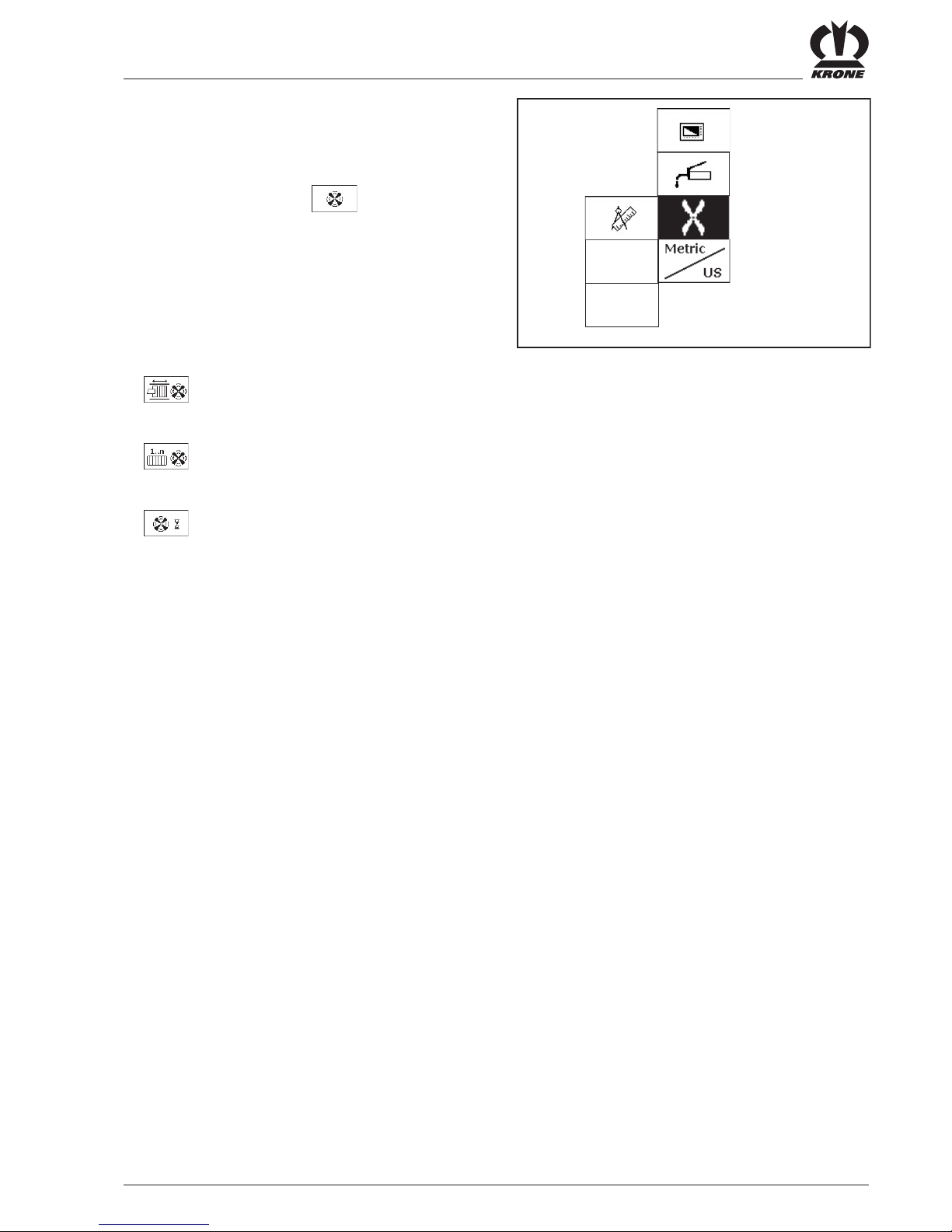
IV - 23
Comfort Control Unit
4.9.8 Menu 1-6 "Knotter blowing"
Displaying the menu
Main menu 1 "Settings" appears
• You can select menu 1-6 with the rotary
potentiometer. The icon is shown in reverse video.
• Press the rotary potentiometer.
The display shows menu 1-6 "Knotter blowing".
Menu level 1-6 "Knotter blowing" is divided into two
menus, depending on how the machine is equipped:
•
= Menu 1-6-1 "Strokes / blow" (without
electronic knotter triggering)
•
= Menu 1-6-2 "Bales / blow" (with
electronic knotter triggering)
• = Menu 1-6-3 "Blow time"
BPK40112
1-6

IV - 24
Comfort Control Unit
4.9.8.1 Menu 1-6-1 "Strokes / blow"
(for machines without electronic knotter
triggering)
Dust and accumulated crop material is removed from
the knotters by compressed air at regular intervals
(depending on the number of piston strokes
completed).
Adjusting the number of piston strokes
Displaying the menu
Menu 1-6 "Knotter blowing" appears
• You can select menu 1-6-1 with the rotary
potentiometer. The icon is shown in reverse video.
• Press the rotary potentiometer.
The display shows menu 1-6-1 "Strokes / blow".
The bar display and value (A) indicate the number of
piston strokes completed.
The icon in the upper line indicates that the
displayed value is saved.
• Press the key for softkey DEF. The factory
setting value is accepted. The icon in the
upper line may disappear.
• Set the desired number of strokes with the rotary
potentiometer. The icon in the top line
disappears.
• Press the rotary potentiometer. The set value is
saved and the icon appears in the upper line.
• You can use the key to close the menu that is
displayed.
The display shows menu level 1-6 "Knotter blowing".
• Pressing the key several times times brings up
the basic screen.
BPK40650
A
BPK40651

IV - 25
Comfort Control Unit
4.9.8.2 Menu 1-6-2 "Bales / blow"
(for machines with electronic knotter triggering)
Dust and accumulated crop material is removed from
the knotters by compressed air at regular intervals
(depending on the number of bales produced).
Settings from 0.5 to 3 bales are possible.
If you select a setting of 0.5, half of the bale is blown
out at the end of the bale.
Adjusting the number of bales
Displaying the menu
Menu 1-6 "Knotter blowing" appears
• You can select menu 1-6-2 with the rotary
potentiometer. The icon is shown in reverse video.
• Press the rotary potentiometer.
The display shows menu 1-6-2 "Bales / blow".
The bar display and value (A) indicate the preselected
number of bales.
The icon in the upper line indicates that the
displayed value is saved.
• Press the key for softkey DEF. The factory
setting value is accepted. The icon in the
upper line may disappear.
• Set the desired number of bales with the rotary
potentiometer. The icon in the top line
disappears.
• Press the rotary potentiometer. The set value is
saved and the icon appears in the upper line.
• You can use the key to close the menu that is
displayed.
The display shows menu level 1-6 "Knotter blowing".
• Pressing the key several times times brings up
the basic screen.
BPK40653
A
BPK40652

IV - 26
Comfort Control Unit
4.9.8.3 Menu 1-6-3 "Blow time"
You can adjust the blowing time on the knotter in this
menu.
Displaying the menu
Menu 1-6 "Knotter blowing" appears
• You can select menu 1-6-3 with the rotary
potentiometer. The icon is shown in reverse video.
• Press the rotary potentiometer.
The display shows menu 1-6-3 "Blow time".
The bar display and value (A) indicate the preselected
cleaning time (blow time) in seconds.
The icon in the upper line indicates that the
displayed value is saved.
• Press the key for softkey DEF. The factory
setting value is accepted. The icon in the
upper line may disappear.
• Set the desired blow time with the rotary
potentiometer. The icon in the top line
disappears.
• Press the rotary potentiometer. The set value is
saved and the icon appears in the upper line.
• You can use the key to close the menu that is
displayed.
The display shows menu level 1-6 "Knotter blowing".
• Pressing the key several times times brings up
the basic screen.
BPK40655
A
BPK40654

IV - 27
Comfort Control Unit
4.9.9 Menu 1-7 "Unit of measure"
(for machines with electronic knotter triggering)
Switch the unit of measure from Metric to US or vice
versa.
Meaning of the icons:
Unit of measure Metric
Unit of measure US
Displaying the menu
Main menu 1 "Settings" appears
• You can select menu 1-7 with the rotary
potentiometer. The icon is shown in reverse video.
• Press the rotary potentiometer.
The display shows menu 1-7 "Unit of measure".
The icon in the upper line indicates that the
displayed status is saved.
• Press the key for softkey DEF. The factory
setting value is accepted. The icon in the
upper line may disappear.
• Set the desired unit of measure with the rotary
potentiometer. The icon in the top line
disappears.
• Press the rotary potentiometer. The set status is
saved and the icon appears in the upper line.
• You can use the key to close the menu that is
displayed.
The display shows menu level 1 "Setting".
• Pressing the key several times times brings up
the basic screen.
BPK40656
BPK40657

IV - 28
Comfort Control Unit
4.9.10 Main Menu 2 “Counters”
Calling the main menu
• Call the main menu with the key.
• You can select main menu 2 with the
rotary potentiometer. The icon is shown in reverse
colours.
• Press the rotary potentiometer.
The display shows menu level 2 “Counters”.
Menu level 2 “Counters” is divided into two menus:
• = menu 2-1 “Customer counters”
• = menu 2-2 “Total counters”
4.9.11 Menu 2-1 “Customer counters”
Calling the menu
Main menu 2 “Counters” is displayed
• You can select menu 2-1 with the rotary
potentiometer. The icon is shown in reverse
colours.
• Press the rotary potentiometer.
The display shows menu 2-1 “Customer counters”.
Meaning of the icons:
• = Total number of bales
• = Number of uncut bales
• = Number of cut bales
(only for machines with X-Cut)
• = Operating hours counter
(counts only when PTO is running)
•
2
= customer counter (1 - 20)
•
m
= Bale length counter (metric in metres)
•
ft
= Bale length counter (US unit of measure
in feet)
• = Knot counter (incl. multibale knot)
The activated customer counter (A) is shown in reverse
colours.
BPK40130
BPK40140
BPK40140
BPK40150
20 100.0
30 50
50
1.5
m
2
2-1
n
h
A

IV - 29
Comfort Control Unit
Activating customer counters
• Turn the rotary potentiometer to select the desired
customer counter (A). Then press the rotary
potentiometer to activate.
The desired customer counter (in this case customer
counter 2) is shown in reverse colours (
2
).
Activating the bale counter (cut / uncut bales
The activated counter is shown in reverse „ “
(in this case the counter for uncut bales) and as a
softkey.
Press the key for softkey to activate the
„Cut bales“ counter.
Changing the number of bales
• Turn the rotary potentiometer to select the desired
customer counter (A). Then press the rotary
potentiometer to activate.
• Select the counter you want to change (cut bales,
uncut bales)
• Press the key for softkey to increase
the number of bales.
• Press the key for softkey to reduce the
number of bales.
At the same time, the season and daily counters in
Menu 2-2 „Total bale counter“ (see Chapter 4.9.10)
as well as the length counter and knot counter are
also changed.
Deleting the customer counter
• Use the rotary potentiometer to place the
customer counter to be deleted between the
wo crossbars (A).
• Press the key for softkey .
The selected customer counter is set to zero.
• You can use the key to close the menu
currently displayed.
The display shows menu level 2 “Counters”.
• Pressing the key twice brings up the basic
screen.
BPK40150
20 100.0
30 50
50
1.5
m
2
2-1
n
h
A

IV - 30
Comfort Control Unit
4.9.12 Menu 2-2 “Total counters”
Calling the menu
Main menu 2 “Counters” is displayed
• You can select menu 2-2 with the rotary
potentiometer. The icon is shown in reverse
colours.
• Press the rotary potentiometer.
The display shows menu 2-2 “Total bale counters”.
The total number of bales is the sum of all bales
pressed. They are not assigned to any customer
counter.
Meaning of the icons:
• = Total number of bales
• = Number of uncut bales
• = Number of cut bales
(only for machines with X-Cut)
• = Operating hours counter
• = Bale counters (cannot be deleted)
• = Season counter 1 (can be deleted)
• = Daily counter 2 (can be deleted)
Deleting season counter 1, or daily counter 2
• Press the key for softkey .
Season counter 1 is set to zero.
• Press the key for softkey .
Daily counter 2 is set to zero.
• You can use the key to close the menu
currently displayed.
The display shows menu level 2 “Counters”.
• Pressing the key twice brings up the basic
screen.
BPK40160
BPK40170

IV - 31
Comfort Control Unit
4.9.13 Main Menu 4 “Service”
Calling the main menu
• Call the main menu with the
key.
• You can select main menu 4
with the
rotary potentiometer. The icon is shown in reverse
colours.
• Press the rotary potentiometer.
The display shows menu level 4 “Service”.
Menu level 4 “Service” is divided into two menus:
• = menu 4-2 “Sensor test, manual”
• = menu 4-4 “Actuator test, manual”
• = menu 4-5 “Current alarms”
4.9.14 Menu 4-2 “Sensor test, manual”
In the manual sensor test, the sensors are checked
for errors. In addition, the sensor type can be
correctly adjusted in the manual sensor test.
There is no guarantee the machine is working
correctly until after the sensors have been adjusted.
The PTO must not be turning during
the sensor test.
Calling the menu
Main menu 4 “Service” is displayed.
• You can select menu 4-2 with the rotary
potentiometer. The icon is shown in reverse
colours.
• Press the rotary potentiometer.
The display shows menu 4-2 “Sensor test, manual”.
Selecting the sensor
• Select the sensor with the rotary potentiometer.
The selected sensor is shown in reverse colours and
is tested.
BPK40180
BPK40190
BPK40200
4-2
B4
state:
8,3V
7,3V
5,2V
2,4V
7,8V
1
B10
BPK40190

IV - 32
Comfort Control Unit
Diagnostics – Namur sensors
State:
• Alive (iron)
• Not alive (no iron)
• Broken cable
• Short circuit
Setting values:
The minimum and maximum setting value with the
sensor alive (metal in front of the sensor) are shown
in the upper part of the bar display.
The current setting value (actual value) is displayed
under the bar display.
The distance from the sensor to the metal must be
adjusted so that in the alive state, the bar lies in the
upper marked area.
Then check whether the bar is in the alive state in the
lower marked area.
No. Sensor icon Description
B1 Flywheel brake
B2 Upper blade bar
B3 Central lubrication
B4 Measuring
B5 Calibration
B6 Packer monitoring
B7 Packer feed
B8 Twine monitoring
B9 Needle connecting rod
B10 Knotter monitoring
B11 Bale chute
Possible sensors (depending on the design of the machine)
Nr. Sensor-Symbol Beschreibung
B12 Setting down bales
B14 Bale ejector
B20 Pickup
B30 Knotter monitor 1*
B31 Knotter monitor 2*
B32 Knotter monitor 3*
B33 Knotter monitor 4*
B34 Knotter monitor 5*
B35 Knotter monitor 6*
BPK40200
4-2
B4
state:
8,3V
7,3V
5,2V
2,4V
7,8V
1
B10
* Enumeration of sensors from left to right (in the
direction of travel)

IV - 33
Comfort Control Unit
Diagnostics button
State:
• Broken cable
• Short circuit
• Pressed
• Not pressed
Setting values:
When the button is held down, the bar must be in the
lower marked area of the bar display. When the
button is released, it should be in the upper area.
No. Icon Description
S1 Blade bar up button
S2 Blade bar down button
S3 Bale ejector in button
Diagnostics – analog sensors
State:
• Broken cable or short circuit
• Defect in the sensor or job computer
Setting values:
The bar must be inside the marked area of the bar
display.
Possible analog sensors
(depending on the design of the machine)
No. Icon Description
S4 Bale ejector out button
S5 Bale chute up button
S6 Bale chute down button
Possible buttons (depending on the design of the machine)
BPK40521
4-2
B15
S2
state
5,1 V
0,9V
3,0V
B17
No. Icon Description
B15 Star wheel (rotate
starwheel: The bar must
always be in the marked
area for a full rotation)
B17 Bale channel flap pressure
(the bar must be in the
lower marked area at 0 bar)
B21 Multi-bale (the system tests
whether the sensor is
defective. The setting must
be made in the fitter
settings)
BPK40210

IV - 34
Comfort Control Unit
Diagnostics – power supply voltages
Nominal voltages:
• 12 V tot.: 12 - 14.5 V
• 12 V Term: 12 - 14.5 V
• SS_5V: 4.5 -5.5 V
• 8 V ana: 8.5 -9.1 V
• 8 V dig: 8.5 -9.1 V
• 12 V Pow2: 12 - 14.5 V
• 12 V Pow3: 12 - 14.5 V
No. Icon Description
U1 Power supply voltage
• You can use the key to close the menu
currently displayed.
The display shows menu level 4 “Service”.
• Pressing the key twice brings up the basic
screen.
No. Icon Description
B18 Plunger force, left
B19 Plunger force, right
Diagnostics – Force sensors
Status messages are only valid if force
sensors have already been adjusted
correctly once.
State:
• Broken cable or short circuit
• Defect in the sensor/force measurement
amplifier or job computer
Setting values:
If a sensor has been changed or the bar is outside
the outer mark, the force measurement amplifier
must be adjusted (with the potentiometer) so that it is
inside the inner mark.
Force sensors
Inner marking:
The bar must be between 1.8 V and 2.0 V
Outer marking:
The bar must be between 1.1 V and 4.0 V
BPK40220
BPK40531

IV - 35
Comfort Control Unit
4.9.15 Menu 4-4 “Actuator test, manual”
The actuator test is used to test the actuators
installed on the machine.
An actuator can only be tested if power is flowing
through it. In the manual actuator test, on the other
hand, the actuator must be controlled manually for a
short time to be able to determine if there are any
errors in the actuator system.
During the actuator test, the PTO
must not be turning.
During the actuator test, the
actuators are controlled by the
system. This may result in the
machine performing unexpected
actions. Because of this, the test must
only be performed from a safe
position outside the area that is
affected by machine parts moved by
the actuators.
Calling the menu
Main menu 4 “Service” is displayed.
• You can select menu 4-4 with the rotary
potentiometer. The icon is shown in reverse
colours.
• Press the rotary potentiometer.
The display shows menu 4-4 “Actuator test, manual”.
Selecting the actuator
• Select the actuator with the rotary potentiometer.
The selected actuator is shown in reverse colours.
BPK40240
BPK40230

IV - 36
Comfort Control Unit
No. Icon Description
Y01 Main valve
Y02 Main valve
Y03 Bale chute
Y04 Bale chute
Y05 Bale ejector
Y06 Bale ejector
Y07 Blade bar
Y08 Blade bar
Y09 Open valve for bale channel
flaps
Possible digital actuators (depending on the design of the machine)
No. Icon Description
Y14 Big-bale
Y15 Multi-bale
Y30 Knotter cleaning
Y31 Central lubrication
M1 Knotter triggering
Diagnostics – digital actuators
Errors are only displayed if the actuator is turned on
and a test is possible for the actuator (see the table
called “Possible digital actuators”). If necessary, the
LED on the plug right on the actuator can be used for
monitoring.
• Press the key for softkey .
State:
• Actuator on
•
Actuator off
•
General actuator error
• No power supply;
fuse is probably defective
(error detection is not possible)
(error detection is not possible)
(error detection is not possible)
(error detection is not possible)
BPK40240
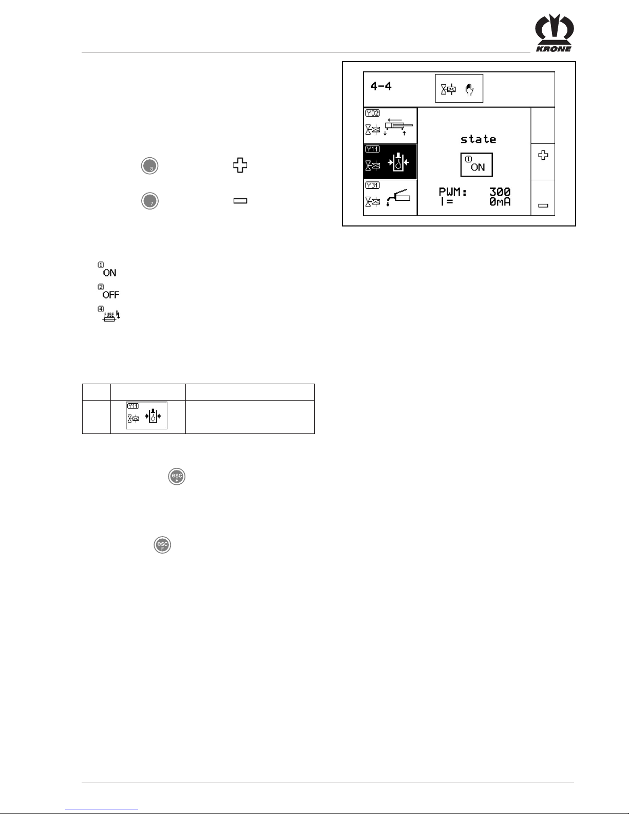
IV - 37
Comfort Control Unit
Diagnostics – analog actuators (for example
pressure limiting valve)
A current (in mA) can be created with the PWM value
(in parts per thousand).
With a value of PWM = 500, the current should be
between 1000 mA and 3000 mA (depending on the
valve that is used and the operating temperature)
• Press the key for Softkey ; PWM is
increased.
• Press the key for Softkey ; PWM is
reduced.
State:
• Actuator on
• Actuator off
• No power supply;
fuse is probably defective
Possible analog actuators
No. Icon Description
Y11 Control valve
• You can use the key to close the menu
currently displayed.
The display shows menu level 4 “Service”.
• Pressing the key twice brings up the basic
screen.
BPK40250

IV - 38
Comfort Control Unit
4.9.16 Menu 4-5 “Current alarms”
Currently pending errors are displayed in “Current
alarms”.
Calling the menu
Main menu 4 “Service” is called.
• You can select menu 4-5 with the rotary
potentiometer. The icon is shown in reverse
colours.
• Press the rotary potentiometer.
The display shows menu 4-5 “Current alarms”.
Currently pending alarms are displayed in the
lower part (1) with the corresponding alarm
number (2).
• Switch to another window with the rotary
potentiometer.
(only possible if there are more than three errors
present at the same time)
BPK40235
BPK40237_2
2
1
BPK40658
2
1

IV - 39
Comfort Control Unit
4.9.17 Main Menu 5 “Info”
Calling the main menu
• Call the main menu with the key.
• You can select main menu 5 with the
rotary potentiometer. The icon is shown in reverse
colours.
• Press the rotary potentiometer.
The display shows menu 5 “Info”.
Page 5-1:
• SW = complete software version of the
machine
• = Version of the job computer
• ISO = ISO software version
• You can use the key to close the menu
currently displayed.
The display shows main menu 5 “Info”.
• Pressing the key brings up the basic screen.
4.9.18 Info window
The display shows menu 5-9 “Number of layers per
bale”.
• You can use the or key to close
whatever menu you have called and return to the
basic screen.
BPK40260
BPK40270_3
5-1
SW: 20080341-4
1: 150200092_11
1: 150200100_01
ISO

IV - 40
Comfort Control Unit
4.9.19 Main Menu 6 “Technician”
Calling the main menu
• Call the main menu with the key.
• You can select main menu 6 with the
rotary potentiometer. The icon is shown in reverse
colours.
• Press the rotary potentiometer.
Main menu 6 “Technician” is password-protected.
The display shows the password query.
BPK40280
BPK40300

IV - 41
Comfort Control Unit
4.10 Alarm Message
If a malfunction occurs in the machine an alarm
message appears in the display and an audio signal
is heard at the same time (rapid-interval horn sound).
Description, possible cause and remedy are shown in
Chapter 4.11.
All functions of the covered menu are
still active.
The softkeys hidden by the alarm
message are deactivated.
Stop audio signal:
• Press the key for softkey .
To reset alarm:
• Press the key for softkey . The alarm is
reset and the audio signal stops.
If the malfunction occurs again, the alarm message
will appear again.
To delete an alarm:
The option for deleting the alarm
should only be used in emergency
situations.
• Press the key for softkey and hold it
down 5 seconds. The alarm is deleted.
If the malfunction occurs again, no alarm message
will appear.
The alarm message does not appear when the
malfunction occurs until after the control unit is
turned off and back on.
BPK40430

IV - 42
Comfort Control Unit
No.
A01
A02
A03
A04
A05
A14
A15
Description
Fuse 2 defective
Fuse 3 defective
(self-repairing)
CAN connection
between terminal and
job computer interrupted
EEPROM error
CAN connection broken
between job computer
and Krone I/O computer
Undervoltage
Overvoltage
Possible cause
Short circuit at the outputs
Short circuit in electrical power
supply for sensors.
CAN wiring defective
Job computer defective
CAN wiring defective
Krone I/O computer inactive
• Tractor battery defective
• Tractor light machine too weak
• 12 V power supply cable on the
tractor side too thin or not
connected directly with the battery
Tractor light machine defective
Remedy
Replace the fuse and then test
all actuators in the actuator
test to determine whether an
actuator has a short circuit.
Check wiring to multi-bale
potentiometer, star wheel,
pressure sensor and force
measurement amplifier
Check the CAN wiring
Replace the job computer
Check the CAN wiring
Check the cables
Replace Krone I/O computer
Connect the Krone connection
cable directly to the battery
Check the dynamo
4.11 Alarm messages

IV - 43
Comfort Control Unit
No.
0
1
2
3
4
5
6
7
8
9
10
11
12
Description
Twine monitoring
Packer monitoring
Baling force exceeded,
left sensor
Baling force exceeded,
right sensor
Knotter monitoring
Measurement
monitoring
Calibration monitoring
Flywheel brake
Needle connecting rod
Bale chute
Baling pressure
exceeded
PTO is turning
Blade bar down
Possible cause
- Twine torn
- Twine end
- Blockage in the intake area of the
packer
Baling force exceeded
If the machine could be subject to a
mechanical overload because the
pressure is too high, the bale
channel flap pressure is lowered to
a non-critical value just before the
overload.
The amount of reduction depends
on the material being baled. The
reduction is less for straw than for
silage.
Knotter is not functioning properly
- Sensor set incorrectly
Sensor measuring defective or set
incorrectly
Sensor calibration defective or set
incorrectly
Flywheel brake applied
Shear screw ruptured
Bale chute up and PTO is turning
Error on the pressure limiting valve
- The pressure sensor could be
defective
PTO is turning upon entry into
sensor or actuator diagnostics or
during diagnostics
- Blade bar is down during baling
Remedy
- Checking the twine and
twine tensioner
- Stop the travel drive
immediately
- Reduce PTO speed
until the blockage is cleared
The following measures must
be taken:
1. In manual mode:
- Lower the pressure
2. In automatic mode:
- If the alarm occurs quite
frequently, reduce the baling
force setting slightly
- Check the knotter and
knotter triggering
- Set the knotter monitoring
sensor correctly
- Adjust the sensor correctly
- Adjust the sensor correctly
- Release the brake
- Replace the shear screw
- Check the needles
- Check the rotation area of
the needles
- Check the twine guide
- Lower the bale chute
- Stop the PTO
- Check the pressure limiting
valve for blockage
- Stop the PTO immediately
- Perform diagnostics with
the PTO stopped
- Raise the blade bar

IV - 44
Comfort Control Unit
Description
Pick-up
Knotter motor
Multi-bale
Packer feed
Error – bale ejector
activation
Measuring/calibrating
Possible cause
Pick-up or cutting system is not
turning Blockage
Knotter motor has not triggered any
knots or the knotter sensor is not
set correctly
It was not possible to set the 2
positions multi-bale or total bales
Packer feed sensor set incorrectly
Bale ejector was activated, even
though the bale chute is still up
The measuring and calibrating
sensors are probably mixed up
Remedy
- Check mechanics
- Cleaning
- Check the knotter motor
electrical system
- Check the mechanics in the
area of the knotter triggering
- Adjust the knotter sensor
correctly
- No compressed air present
- Adjust the multi-bale sensor
correctly
- Check the mechanics in the
area of the knotter triggering
- Fault in multi-bale valve
(valve jammed, coil
defective, etc.)
- Check the electronics in the
area of the multi-bale
interlock
- Adjust the sensor correctly
- Lower the bale chute and
then activate the bale
ejector
- Exchange the connectors
for the measuring and
calibrating sensors
No.
16
17
18
19
20
21

IV - 45
Comfort Control Unit
No.
22
23
24
25
26
27
28
101
102
103
104
105
Description
Knotter monitoring1
(knotter on far left (in
the direction of travel))
Knotter monitoring2
(second knotter from
the left (in the direction
of travel))
Knotter monitoring3
(third knotter from the
left (in the direction of
travel))
Knotter monitoring4
(fourth knotter from the
left (in the direction of
travel))
Knotter monitoring5
(fifth knotter from the
left (in the direction of
travel))
Knotter monitoring6
(sixth knotter from the
left (in the direction of
travel))
Central lubrication
monitoring
Twine monitoring
sensor
Packer monitoring
sensors
Packer feed sensor
Blade bar sensor, top
Blade sensor active
Possible cause
Knot missing
No more twine
Knot missing
No more twine
Knot missing
No more twine
Knot missing
No more twine
Knot missing
No more twine
Knot missing
No more twine
No grease
Blockage
Pump not running
Sensor or line defective
Sensor or line defective
Sensor or line defective
Sensor or line defective
Sensor or line defective
Remedy
Check knotter
Check knotter
Check knotter
Check knotter
Check knotter
Check knotter
- Add grease
- Clean central lubrication
- Check electrical system and
pump
- Perform a sensor test
- Check the sensor and line
for damage
- Perform a sensor test
- Check the sensor and line
for damage
- Perform a sensor test
- Check the sensor and line
for damage
- Perform a sensor test
- Check the sensor and line
for damage
- Perform a sensor test
- Check the sensor and line
for damage

IV - 46
Comfort Control Unit
No.
106
107
108
109
110
111
112
113
114
115
116
117
118
119
120
Description
Knotter monitoring
sensor
Measuring force
sensor
Calibration force
sensor
Flywheel brake sensor
Needle connecting rod
sensor
Bale chute sensor
Force sensor, right
Force sensor, left
Hydraulic pressure
sensor
Sensor for setting
down bales
Bale ejector sensor
Star wheel sensor
Pick-up sensor
Bale chute up button
Bale chute down
button
Possible cause
Sensor or line defective
Sensor or line defective
Sensor or line defective
Sensor or line defective
Sensor or line defective
Sensor or line defective
Sensor, measurement amplifier or
line defective
Sensor, measurement amplifier or
line defective
Sensor or line defective
Sensor or line defective
Sensor or line defective
Sensor (rotary potentiometer) or
line defective
Sensor or line defective
Button or line defective
Button or line defective
Remedy
- Perform a sensor test
- Check the sensor and line
for damage
- Perform a sensor test
- Check the sensor and line
for damage
- Perform a sensor test
- Check the sensor and line
for damage
- Perform a sensor test
- Check the sensor and line
for damage
- Perform a sensor test
- Check the sensor and line
for damage
- Perform a sensor test
- Check the sensor and line
for damage
- Check the sensor and line
for damage
- Check the sensor and line
for damage
- Perform a sensor test
- Check the sensor and line
for damage
- Perform a sensor test
- Check the sensor and line
for damage
- Perform a sensor test
- Check the sensor and line
for damage
- Perform a sensor test
- Check the sensor and line
for damage
- Perform a sensor test
- Check the sensor and line
for damage
- Perform a sensor test
- Check the button and line
for damage
- Perform a sensor test
- Check the button and line
for damage

IV - 47
Comfort Control Unit
No.
121
122
123
124
125
126
127
128
129
130
131
132
Description
Bale ejector out button
Bale ejector in button
Blade bar up button
Blade bar down button
Multi-bale sensor
Sensor - knotter
monitor1
Sensor - knotter
monitor2
Sensor - knotter
monitor3
Sensor - knotter
monitor4
Sensor - knotter
monitor5
Sensor - knotter
monitor6
Sensor - central
lubrication
Possible cause
Button or line defective
Button or line defective
Button or line defective
Button or line defective
Sensor (rotary potentiometer) or line
defective
Sensor or supply line defective
Sensor or supply line defective
Sensor or supply line defective
Sensor or supply line defective
Sensor or supply line defective
Sensor or supply line defective
Sensor or supply line defective
Remedy
- Perform a sensor test
- Check the button and line
for damage
- Perform a sensor test
- Check the button and line
for damage
- Perform a sensor test
- Check the button and line
for damage
- Perform a sensor test
- Check the button and line
for damage
- Perform a sensor test
- Check the sensor and line
for damage
- Perform a sensor test
- Check the button and line
for damage
- Perform a sensor test
- Check the button and line
for damage
- Perform a sensor test
- Check the button and line
for damage
- Perform a sensor test
- Check the button and line
for damage
- Perform a sensor test
- Check the sensor and line
for damage
- Perform a sensor test
- Check the sensor and line
for damage
- Perform a sensor test
- Check the sensor and line
for damage

IV - 48
Comfort Control Unit

IV - 49
ISO Control
4.12 ISO Control
4.12.2 Mounting
When mounting the control unit, make
certain the connection cables are not
stretched and cannot come in contact
with the tractor wheels.
LBS_0002
1
4.12.1 Working Principle
ISO control is used exclusively for machines and systems that are compliant with Application Level 1 of International
Standards Organisation (ISO) 11783. The purpose of ISO 11783 is to provide a complete uniform system for
electronic systems in the vehicle. The uniform, easy to understand system required by ISO 11783 is intended to
facilitate communication between the different electronic control units. The purpose of simple adjustable control
elements that are separate from the actual display is to make it possible to use the display as a performance monitor
for the tractor and as a monitor for an ISO-11783 attached device.
Install the cable harness included with delivery.
To do this:
• Connect the power supply cable (12 V) on the
tractor side to the 3-prong power outlet (DIN 9680)
and on the machine side with the Delphi plug (5).
• The Delphi plug (5) is located on the left-hand side
of the machine (in the direction of travel) on the
metal cover close to the flywheel.
• Connect the cable included with delivery to the
socket (4) on the metal cover on the left-hand side
(in the direction of travel) close to the flywheel. Also
connect with the socket of the control unit.
• Attach the 9-pin ISO plug to the ISO bus socket (1)
on the tractor.
BPK40659
5
4

IV - 50
ISO Control
The ISO control unit provides information and control
functions in the ISO terminal display via the attached
device.
The ISO terminal operates in a manner similar to the
KRONE in-cab Comfort kit. Before starting the system
up for the first time, please read the section on
KRONE in-cab Comfort kit in the operating
instructions.
One important difference compared to KRONE in-cab
Comfort kit is the arrangement of softkeys, determined
by the ISO terminal that is selected.
Functions that differ from the in-cab Comfort kit are
described below.
One significant difference compared to the KRONE incab Comfort kit is that the functions of the rotary
potentiometer (clockwise rotation, anticlockwise
rotation, and pressing the rotary potentiometer) are
replaced by the softkeys below.
4.12.3 Functions that Differ from the KRONE In-cab Comfort Kit
KRONE in-cab Comfort kit
„Clockwise rotation“ and „anticlockwise rotation“ of
the rotary potentiometer to scroll forward and backward respectively.
„Clockwise rotation“ and „anticlockwise rotation“ of
the rotary potentiometer to increase and decrease
values respectively.
Pressing the rotary potentiometer to accept the value
You can use the $$$ key to go to the previous
screen or the menu level above the current one.
The $$$ key can be used to bring up the menu.
Corresponds to softkey $$$ for the ISO terminal
Scroll forward and backward
Increase value Reduce value
Accept value Closes the menu
that had been opened
Bring up a menu level
The values for the „Bale channel flaps,
pressure / force“, „Bale length“ and
„Number of multibales“ that are set
with the rotary potentiometer in the
basic screen of the KRONE in-cab
Comfort kit are set instead on the ISO
terminal with the Selection
key assigned by the ISO terminal.
(See operating instructions of the ISO
terminal manufacturer.)
OK
ESC

IV - 51
ISO Control
Menu item 1-4 “Contrast“ of the KRONE in-cab Comfort kit cannot be
brought up on the ISO terminal.
Instead the setting is made directly
with the ISO terminal (if available). See
operating instructions of the ISO
terminal manufacturer.
Menu item 1-7 “Unit of measure“ of
the KRONE In-cab Comfort kit cannot
be displayed on the ISO terminal. A
setting is made directly via the ISO
terminal. (if available) (refer to the
operating instructions of the ISO
terminal manufacturer)
Audio signals must be enabled from
the terminal if necessary
(see operating instructions of the ISO
terminal manufacturer).

IV - 52
ISO Control

V - 1
Medium Control Unit
5 Medium Control Unit
5.1 General Description
The electronic equipment of the Big Pack Baler consists
essentially of the job computer, the control unit and the
control and function elements.
The job computer (1) is located on the front left of the
machine under the side hood.
Its functions are:
– Regulation of the baling density
– Bale counter
– Control of the actuators installed on the machine
– Transfer of alarm messages
– Sensor/actuator diagnostics
The control unit (2) communicates information to the
driver and performs settings to operate the Big Pack
Baler. This information is received and further processed
by the job computer.
The control unit (2) must be protected
from water.
If the Big Pack Baler will not be used
for an extended period (as in winter,
for example), the control unit (2) must
be stored in a dry place.
For mounting and repair jobs, es-pecially
for welding jobs on the Big Pack Baler,
disconnect the power supply from the
control unit (2).
Overvoltage can damage the
electronics of the control unit.
BPM50540
1
BPM50021
2

V - 2
Medium Control Unit
5.2 Mounting
Mount the control unit with its support (1) where it can
be seen by the driver. .
Direct fastening
• Fasten the support (1) using the drill holes (2)
already present.
• The control unit (3) is held in place on the magnetic
plate (4) on the support (1).
1
2
4
3
BPM50420
1
2
BPM50390

V - 3
Medium Control Unit
Electrical power supply
When installing, take care that the
connecting cables are not stretched
and cannot come in contact with the
tractor wheels.
• Connect the power supply cable (12 V) on the
tractor side to the 3-prong power outlet (DIN 9680)
and on the machine side with the Delphi plug (5).
• The Delphi plug (5) is located on the left-hand side
of the machine (in the direction of travel) on the
metal cover close to the flywheel.
BPM50022
2
3
Control unit
• Connect the cable included with delivery to the
socket (4) on the metal cover on the left-hand side
(in the direction of travel) close to the flywheel. Also
connect with the socket (3) of the control unit.
BPK40659
5
4

V - 4
Medium Control Unit
5.3 Control Unit
Overview
1 On/Off button
2 Display
3 Keys (1 - 3)
4 Menu key (4)
5 “+” key (5)
6 Esc key (6)
7 “-” key (7)
8 OK key (8)
BPM50010
1
4
3
5
6
7
8
2
 Loading...