


Operating Instructions No.: 956-1 GB
Big Pack Baler
Big Pack 890 XC
Big Pack 1270 XC
Big Pack 1290 XC
(from Mach. No. 561 000)
Dear Customer,
These are the operating instructions for the KRONE product that you
have purchased.
These operating instructions contain important information for the
correct use and safe operation of the machine.
Should these operating instructions have become unusable completely
or partially for any reason, you can obtain replacement operating
instructions for your machine by stating the number quoted on the
reverse.
We
declare in our sole responsibility that the product
to which this declaration refers corresponds to the relevant basic safety and health requirements of the EU
Directive 89/392/EU, 3, Change Directive of 22.7.93.
EU Declaration of Conformity
corresponding to the EU Directive 89/392/EU
Maschinenfabrik Bernard Krone GmbH
Heinrich-Krone-Str. 10, D-48480 Spelle
Krone Big Pack Baler
Types: Big Pack 890 / XC; Big Pack 1270 / XC; Big Pack 1290 / XC
Spelle, 01.04.2003
(Dr.-Ing. Josef Horstmann, Managing Director)
(ppa. Dr.-Ing. Klaus Martensen, Head of Design and Development)
(Wolfgang Ungruh, Head of Quality Assurance)

1
Contents
Contents
1 General ............................................................................................... I -1
1.1 Purpose .................................................................................................................. I -1
1.2 Technical Data ........................................................................................................ I -1
1.2.1 General.................................................................................................................. I -1
1.2.2 Manufacturer’s address.......................................................................................... I -1
1.2.3 Certificate .............................................................................................................. I -1
1.2.4 Identification ........................................................................................................... I -1
1.2.5 Data for enquiries and orders ................................................................................. I -1
1.2.6 Use as intended ..................................................................................................... I -2
1.2.7 General technical data ........................................................................................... I -2
1.2.8 Technical Data........................................................................................................ I -3
2 Safety..................................................................................................II -1
2.1 Identifying symbols in the operating instructions .................................................... II -1
2.2 Safety instructions and accident prevention regulations......................................... II -1
2.2.1 Personal qualification and training.......................................................................... II -1
2.2.2 Dangers in the case of non-compliance with the safety instructions .................... II -1
2.2.3 Safety-conscious working....................................................................................... II -1
2.2.4 Safety and accident prevention regulations............................................................ II -2
2.2.5 Hitched implements................................................................................................ II -3
2.2.6 PTO operation ........................................................................................................ II -3
2.2.7 Hydraulic System ................................................................................................... II -3
2.2.8 Tyres....................................................................................................................... II -4
2.2.9 Maintenance........................................................................................................... II -4
2.2.10 Unauthorised conversion and spare parts production ............................................ II -4
2.2.11 Inadmissible modes of operation............................................................................ II -4
2.3 Introduction............................................................................................................. II -6
2.3.1 Position of the safety labels on the machine .......................................................... II -6
2.4 Overview of the Big Pack baler with tandem axle (Left-hand side) ........................ II -8
2.5 Overview of the Big Pack baler with tandem axle (right-hand side) ....................... II -9
2.6 Mode of operation of the BIG PACK XC baler ...................................................... II -10
3. Preparations on the Big Pack Baler................................................III -1
3.1 Special safety instructions ..................................................................................... III -1
3.2 Adjusting the drawbar height ................................................................................. III -1
3.3 Adapting the main PTO shaft ................................................................................ III -2
3.4.1 General.................................................................................................................. III -3
3.4 Commissioning the Big Pack baler........................................................................ III -3
3.4.2 Hitching the Big Pack baler onto the tractor .......................................................... III -5
3.4.3 On-Board Hydraulic System .................................................................................III -11
3.4.4 Road travel .......................................................................................................... III -12
3.4.5 Detaching the Big Pack baler .............................................................................. III -13
3.4.6 Ladder ................................................................................................................ III -15
3.4.7 Fire extinguisher.................................................................................................. III -16
3.4.8 Moving without connected compressed air brake................................................ III -16

2
Contents
4. Control unit (Medium / Comfort) .................................................... IV -1
4.1 General description ............................................................................................... IV -1
4.2 Attaching ............................................................................................................... IV -1
4.3 Control panel ......................................................................................................... IV -2
4.4 Operational readiness ........................................................................................... IV -2
4.4.1 Manual mode basic screen.................................................................................... IV -3
4.4.2 Automatic mode basic screen ............................................................................... IV -5
4.4.3 Buttons on the machine......................................................................................... IV -6
4.4.4 Description of the baling process ..........................................................................IV -7
4.5 Menu guidance......................................................................................................IV -8
4.6 Counters..............................................................................................................IV -10
4.7 Opening and closing the bale channel flaps........................................................ IV -11
4.8 Activate/deactivate knotter signal ........................................................................ IV -11
4.9 Adjusting the sensitivity of the direction display...................................................IV -12
4.10 Sensor test ..........................................................................................................IV -13
4.10.1 Automatic sensor test..........................................................................................IV -14
4.10.2 Manual sensor test .............................................................................................. IV -15
4.11 Actuator test ........................................................................................................IV -18
4.11.1 Automatic actuator test........................................................................................ IV -19
4.11.2 Manual actuator test............................................................................................IV -20
4.12 Currently pending alarm ......................................................................................IV -22
4.13 Krone Service......................................................................................................IV -22
6.14 Info ...................................................................................................................... IV -22
4.15 Contrast............................................................................................................... IV -23
4.16 Alarm message window....................................................................................... IV -23
4.17 Alarm messages.................................................................................................. IV -24
4.18 Circuit diagrams ..................................................................................................IV -27
4.18.1 Medium control unit ............................................................................................. IV -27
4.18.2 Comfort control unit ............................................................................................. IV -37
5. Control unit - Basic .......................................................................... V -1
5.1 General description ................................................................................................ V -1
5.2 Attaching ................................................................................................................ V -1
5.3 Operation................................................................................................................ V -1
5.4 Description of the baling process ...........................................................................V -2
5.5 Circuit diagram of the basic control unit ................................................................. V -3
6 Working with the Big Pack Baler..................................................... V -1
6.1 Special safety instructions...................................................................................... V -1
6.2 Basic setting on the Big Pack Baler........................................................................ V -1
6.2.1 Pick-up ...................................................................................................................V -1
6.2.1 Cutting system XC.................................................................................................. V -3
6.2.1.3 Cutting length .........................................................................................................V -3
6.2.1.1 Special safety instructions...................................................................................... V -3
6.2.1.2 General................................................................................................................... V -3
6.2.1.4 Changing blades .................................................................................................... V -4
6.2.1.5 Zero setting of blades.............................................................................................V -5
6.2.2 Bale chute .............................................................................................................. V -6
6.2.2.1 Hydraulically collapsable bale chute with rollers.....................................................V -6
6.2.2.2 Emptying the baling channel .................................................................................. V -7
6.2.3 Regulating the force of pressure ............................................................................V -8

3
Contents
6.3 Length adjustment of big bales............................................................................... V -9
6.4 Twine...................................................................................................................... V -9
6.4.1 General................................................................................................................... V -9
6.4.2 Set the tying twine in place...................................................................................V -10
6.4.3 Threading the tying twine .....................................................................................V -12
6.4.4 Electrical twine empty display............................................................................... V -14
6.4.5 Twine motion display for upper thread (double knotter)........................................V -15
6.4.6 Triggering the typing process manually................................................................ V -15
7. Settings ........................................................................................... VII -1
7.1 Special safety instructions .................................................................................... VII -1
7.2 Needle setting ...................................................................................................... VII -1
7.2.1 Lateral adjustment of the needles ........................................................................ VII -1
7.2.2 Height of the needles on the knotter..................................................................... VII -2
7.2.3 Needles' Upper Dead Centre ............................................................................... VII -2
7.2.4 Needles in idle position......................................................................................... VII -3
7.2.5 Needles to the baling ram..................................................................................... VII -4
7.3 Twine bar.............................................................................................................. VII -5
7.3.1 Setting for the twine bar ....................................................................................... VII -5
7.4 Setting of the twine brake..................................................................................... VII -6
7.5 Baling ram setting................................................................................................. VII -7
7.6 Adjusting the packer relative to the baling ram..................................................... VII -8
7.7 Adjusting the clutch .............................................................................................. VII -9
7.8 Absorbing mechanism.......................................................................................... VII -9
7.8.1 Lateral adjustment of the absorbing mechanism.................................................. VII -9
7.8.2 Adjusting the absorber mechanism ...................................................................... VII -9
7.9 Adjusting the triggering sensitivity ...................................................................... VII -10
7.10 Adjusting the flywheel cleaning (for Big Pack 890).............................................VII -10
7.11 Position of the sensors / buttons ........................................................................ VII -11
7.12 Adjusting the sensors .........................................................................................VII -13
7.13 Basic setting of the flywheel belt brake .............................................................. VII -14
8 Care and maintenance .................................................................. VIII -1
8.1 Special safety instructions ................................................................................... VIII -1
8.2 General................................................................................................................ VIII -1
8.3 Cleaning .............................................................................................................. VIII -2
8.4 Tyres....................................................................................................................VIII -2
8.5 Opening the front hood........................................................................................ VIII -2
8.6 Hydraulics............................................................................................................ VIII -3
8.6.1 Special safety instructions ................................................................................... VIII -3
8.6.2 On-board hydraulic system..................................................................................VIII -3
8.6.3 Circuit diagrams of the hydraulic system............................................................. VIII -6
8.7 Checking and changing the oil on the gearboxes..............................................VIII -10
8.7.1 General.............................................................................................................. VIII -10
8.7.2 Main gearbox..................................................................................................... VIII -10
8.7.3 Packer gearbox ................................................................................................. VIII -10
8.7.4 Distributor gearbox ............................................................................................ VIII -11
8.7.5 Upper and lower pick-up gearbox...................................................................... VIII -11
8.7.6 Cutting system drive gearbox for the Big Pack XC, upper and lower ................ VIII -12
8.8 Compressed air system..................................................................................... VIII -13
8.8.1 General.............................................................................................................. VIII -13

4
Contents
8.8.2 Compressed air storage tank ............................................................................ VIII -13
8.8.3 Brake cylinder.................................................................................................... VIII -14
8.9 Replacing the guide rollers on the packers ....................................................... VIII -14
9 Lubrication ....................................................................................... IX -1
9.1 Special safety instructions..................................................................................... IX -1
9.2 General.................................................................................................................. IX -1
9.3 Lubrication.............................................................................................................IX -1
9.4 Central grease lubrication system .........................................................................IX -7
9.4.1 Method of operation of the BEKA-MAX central grease lubrication system:........... IX -7
9.4.2 Design of the BEKA-MAX central grease lubrication system: ...............................IX -7
9.4.3 Function description, central lubricating pump EP-1: ............................................IX -8
9.4.4 Method of operation of progressive distributors MX-F:.......................................... IX -9
9.4.5 Description of control........................................................................................... IX -10
9.4.6 Technical details: ................................................................................................. IX -11
9.4.7 Signals of control.................................................................................................IX -12
10 Tying Unit .......................................................................................... X -1
10.1 Special instructions ................................................................................................ X -1
10.1.1 Safety instructions .................................................................................................. X -1
10.1.2 Placing the machine in service ............................................................................... X -1
10.2 Single knotter .........................................................................................................X -1
10.2.1 Knotter unit ............................................................................................................. X -1
10.2.2 Knotter hook ........................................................................................................... X -2
10.2.3 Cord holder............................................................................................................. X -2
10.2.4 Knot extractor ......................................................................................................... X -3
10.3 Double knotter ........................................................................................................ X -4
10.3.1 The knotter hook .................................................................................................... X -4
10.3.2 The twine retainer................................................................................................... X -4
10.3.3 The blade lever....................................................................................................... X -5
10.3.4 Aligning the blade lever .......................................................................................... X -6
11 Storage for winter........................................................................... XI -1
11.1 Special safety instructions..................................................................................... XI -1
11.2 General.................................................................................................................. XI -1
12 Placing the machine in service again........................................... XII -1
12.1 Special safety instructions.................................................................................... XII -1
12.2 General................................................................................................................. XII -1
12.3 Overload coupling on the flywheel........................................................................ XII -1
13 Malfunctions, causes and remedies ............................................ XIII -1
13.1 Special safety instructions...................................................................................XIII -1
13.2 Needle yoke does not rise up .............................................................................. XIII -1
13.3 Additional malfunctions........................................................................................ XIII -2
13.4 Malfunctions on the double knotter...................................................................... XIII -6
13.5 Troubleshooting in the central lubrication system................................................ XIII -9

I -1
General
1 General
These operating instructions contain basic information
that has to be observed in mounting, operation and
maintenance. Therefore these operating instructions
must absolutely be read by the personnel before use
and start-up and must be accessible to the personnel.
Not only must the general safety instructions listed
under this main item of safety be complied with, but
also the special safety instructions inserted under the
other main items.
1.1 Purpose
The Big Pack 890 / XC; Big Pack 1270 / XC and
Big Pack 1290 / XC balers are balers with the
„Variable Feeding System“. They bale highly
compacted and dimensionally stable big bales
with a length of 1.0 to 2.7 m under all
conditions. The Big Pack baler is equipped as
standard with a tying unit and a one-part bale
chute.
1.2 Technical Data
1.2.1 General
These operating instructions are valid for the Big Pack
balers:
Big Pack 890 / XC,
Big Pack 1270 / XC and
Big Pack 1290 / XC.
1.2.2Manufacturer’s address
Maschinenfabrik Bernard Krone GmbH
Heinrich-Krone-Str. 10
D-48480 Spelle (Germany)
Phone: 0 59 77/935-0
Telefax: 0 59 77/935-339
e-mail: info.ldm@krone.de
1.2.3 Certificate
Declaration of conformity (requirements of the EU
machinery Directive 89/392/EU, 3rd Change Directive of
22.7.93 are fulfilled).
See inside title page
1.2.4Identification
The machine data are located on a nameplate (1). This is
located on the right side of the machine under the angular
gear of the cutting system.
Type
Year of build
Vehicle
ident No.
The entire identification has the value
of a certificate and may not be
changed or made illegible!
1.2.5Data for enquiries and orders
When enquiring about the machine and ordering
spare parts, state the type designation, the
vehicle ident No. and the year of build of the
machine.
Original spare parts and accessories
authorised by the manufacturer serve
for safety. The use of other parts can
cancel the liability for the
consequences arising from this.
M
asc
hinenfabrik
B
ernar
d
K
rone Gm
b
H
H
einric
h
-
K
rone
-
S
t
r
. 10 D-
48480
S
pell
e
M
ade in
G
erman
y
BP800016

I - 2
General
1.2.6Use as intended
The Big Pack 890 / XC; Big Pack 1270 / XC and
Big Pack 1290 / XC balers are built exclusively for
customary use in agricultural work (use as
intended).
Any use extending beyond this is considered as not as
intended. The manufacturer is not liable for damage
resulting from this, the user alone bears the risk for
this.
Use as intended includes compliance with the operating,
maintenance and repair conditions specified by the
manufacturer.
Permissible crops:
Agricultural crops such as hay, straw and grass
silage.
Collecting and baling other materials is
permitted only in agreement with the
manufacturer.
A basic prerequisite is in any event the
formation of windrows of the baled
product and the independent collection
by the pick-up when driving over.
1.2.7General technical data
• Travelling on the road permitted only with emptied
baling channel and folded in bale chute.
• Permissible maximum speed: 40 km/h / 50 km/h
(65 km/h).
• In the case of machines with operating permission,
observe the requirements in the operating permission!
• Observe the maximum supporting and tensile load of
the hitch on the tractor.
• Switch off the electrical operation when travelling on
the road!
All information, illustrations and technical data in
these operating instructions correspond to the latest
state at the time of publication. We reserve the right
to make design changes at any time and without
notification of reasons.

I -3
General
1.2.8 Technical Data
Technical Data Big Pack 890 / XC
Big Pack 890 Big Pack 890 XC
Sin gl e axl e Tandem Sin gl e axl e Tand em
Maximum permissible speed 40 km/h 50 km/h 65 km/h 40 km/h 50 km/h 65 km/h
Working po si tion len gth[mm] 9140
Transport position length[mm] 7895
Hei ght [mm] 2910
Weight [kg] 6580 6950 7480 7850
Width [mm]
2450 / 2600 2540 / 2640 2450 / 2600 2540 / 2640
Tyres
600/50-22,5
700/45-22,5
500/55-20
550/45-22,5
600/50-22,5
700/45-22,5
500/55-20
550/45-22,5
Tyre pr es s ure [bar] 1.5 2 1.5 2
Track wid th [mm] 1820 2040 1820 2040
Baling channel Height [mm]
900
800
Wid th [mm]
Baling length [mm] from 1000 to 2700 (can be adjusted continuously)
Receiving width [mm] 1950 (2380)
Number of knotter mechanisms 4
Output requirement 65 kW (85 PS ) 88 kW (115 PS)
Cutting system (number of
blades)
-
16
Drive friction coup l in g 1350 N m 1550 Nm
Flywheel o v erload coupling Wedge c ircuit 4500 Nm or shear screw M 10 x 55 DIN 931-8.8
Pick-u p ove rload coup ling
Star ratchet 400 Nm or 600 N m (XC) or shear screw 8 x 35 DIN 931-8.8
Cutting system cam-type cut-o ut
clutch
5500 Nm
Packer overload coupling
Cam-type cut-out clutch 14500 Nm or shear screw M 20 x 60 DIN 931-8.8
Needle connecting rod Shear screw M10 x55 DIN 931-10.9

I - 4
General
Technical Data Big Pack 1270 / XC
Big Pack 1270 Big Pack 1270 XC
Single axle Tandem Single axle Tandem
Maximum permi ssib le speed 40 km/h 50 km/h 65 km/h 40 km/h 50 km/h 65 km/h
Working position length[mm] 9140
Transport position length[mm] 7895
Height [mm] 2810
Weight [kg] 7240 7610 8430 8800
Width [mm] 3000 2540 2740* 3000 2540 2740*
Tyres 700/45-22.5 500/55-20 700/45-22.5 500/55-20
Tyre pr es s ure [bar] 1.5 2 1.5 2
Track width [mm] 2220 2040 2290* 2220 2040 2290*
Baling channel He i ght [mm]
700
1200
Width [mm]
Baling length [mm] from 1000 to 2700 (can be adjusted continuously)
Receiving width [mm] 1950 (2380)
Nu mbe r of kno tter mec h an i sms 6
Output requirement 69 kW (90 PS) 92 kW (120 PS)
Cutting system (number of
blades)
-
26
Drive friction c oupling 1350 N m 1550 Nm
Flywheel overload coupling Wedge circuit 4500 Nm or shear screw M 10 x 55 DIN 931-8.8
Pick-u p ove rload coup li n g
Star ratchet 400 N m or 600 Nm (XC ) or shear screw 8 x 35 DIN 931-8.8
Cutting system cam-type cut-ou t
clutch
5500 N m
Packer overload coupling
Cam-type cut-out clutch 14500 Nm or shear screw M 20 x 60 DIN 931-8.8
Needle connecting rod Shear screw M10 x55 DIN 931-10.9
* Tandem unit with trailing steering axle

I -5
General
Technical Data Big Pack 1290 / XC
Big Pack 1290 Big Pack 1290 XC
Sin gl e axl e Tandem Sin gl e axl e Tand em
Maximum permissible speed 40 km/h 50 km/h 65 km/h 40 km/h 50 km/h 65 km/h
Working po si tion len gth[mm] 9140
Transport position length[mm] 7895
Hei ght [mm] 2910
Weight [kg] 7860 8230 9050 9 420
Width [mm] 3000 2540 2740* 2980 2540 2740*
Tyres 700/45-22.5 500/55-20 700/45-22.5 500/55-20
Tyre pr es s ure [bar] 1.5 2 2 2
Track width [mm] 2220 2040 2290* 2220 2040 2290*
Baling channel Height [mm]
900
1200
Wid th [mm]
Baling length [mm] from 1000 to 2700 (can be adjusted conti nuously)
Receiving width [mm] 1950 (2380)
Number of knotter mechanisms 6
Output requirement 77 kW (100 PS) 100 kW (130 PS)
Cutting system (number of
blades)
-
26
Drive friction coup l in g 1350 N m 1550 Nm
Flywheel o v erload coupling Wedge c ircuit 4500 Nm or shear screw M 10 x 55 DIN 931-8.8
Pick-u p ove rload coup ling
Star ratchet 400 Nm or 600 N m (XC) or shear screw 8 x 35 DIN 931-8.8
Cutting system cam-type cut-o ut
clutch
5500 Nm
Packer overload coupling
Cam-type cut-out clutch 14500 Nm or shear screw M 20 x 60 DIN 931-8.8
Needle connecting rod Shear screw M10 x55 DIN 931-10.9
* Tandem unit with trailing steering axle

I - 6
General
PTO speed 1000 rpm
PTO shaft wide-angle on the tractor side
free-wheeling clutch on the machine side
Hitch Hitch coupling
Swinging drawbar (perm. supporting load min. 1200 kg; XC =
1500 kg) (drawbar adjustable in height)
Caution! For adjustment the
hexagonal head screws must be tightened with a tightening
torque according to the „Tightening torque“ table in
section 8.2.
Support Support base, retractable - adjustable in height.
Pick-up drum Hydraulic lift
Height adjustment by perforated bar on the supporting wheel.
Tine mounting 5 pcs.
Number of tines 13 (16) double tines/tine mounting
Lateral feed Right and left worm conveyor
Crop f eed Forced intake by feed packer drum
Feed packer drum with 5 feed packers, 1 feeder packer
In XC a cutting drum is placed in front.
Baling ram Length of stroke 750 mm
50 / 38.5 strokes per minute
The baling ram moves on 4 rollers
5 / 7 blades on the baling ram
2 blades in the baling channel
Setting the baling density Basic version with pure pressure regulation otherwise
electronic-hydraulic force control by an adjustable
pressure valve, adjustable from the tractor
Twine box on both sides, for 16 twine rolls each
Twine Plastic with 120-140 m/kg
For twine roll end and torn twine Electrical twine control with acoustic
and optical signal.
Bale ejector / bale unloading One-part bale chute (must be hinged up
in transport).
Operation according to Basic - Medium - Comfort version
at the machine or from the tractor
Holding brake Operation by hand crank at the rear left of the
baler
Brake connections on the tractor
Baler with compressed air operated brake Dual-line brake system required
Baler with hydraulically operated brake Connection for hydraulic brake system required
Max. working pressure 120 bar

I -7
General
Lubricant Quantities and Designations for the Gearboxes
Quantity (ltr.) Designation/Brand Designation/Brand
Main gearbox 15
Packer gearbox 2.5
Knotter/packer drum transfer gearbox 0.8
Pick-up gearbox above 0.5
Pick-up gearbox below 0.5
Cutting system gearbox
for XC above 1.0
Cutting system gearbox
for XC below 2.5
Oil Quantities and Designations for the On-Board Hydraulic System
Quantity (ltr.) Designation/Brand Designation/Brand
Oil tank on baler 10 Fuchs Renolin MR 46 MC
BP Energol SHF 46
Shell Tellus 46
Esso Univis N 46
Aral Vitan Vs 46
Bio-Degradable
Lubricants
SAE 90 or
Esso-Spartan EP 150
Shell Omala Oil 150
Fuchs - EP 85 W90
Castrol EPX 90
on request
With bio-degradable oils the changing intervals must be complied with absolutely because of
ageing of the oils.
on request
Hydraulic connections on the tractor
Raising the pick-up (yellow protective cap) single-acting control valve
Locking the steering axle (green protective cap) single-acting control valve
Depending on version:
Basic and Medium - Electronic:
Hinging blade bar (red protective cap) double-acting control valve
Residual bale ejector/roller chute (blue protective cap) double-acting control valve
Comfort - Electronic:
Supply control block (red protective cap) single-acting control valve (NW 15)
Return control block (blue protective cap) tank return (NW 18)
Load sensing line (blue protective cap) LS connection (NW 12)
With tractors with load sensing hydraulics, use connections provided for this.
Electrical connections on the tractor
Lighting of the baler 7-pin socket DIN ISO 1124
Supply of the electronic control of the baler 3-pin socket DIN 9680
with continuous power (direct battery connection required)
Machines with 65 km/h approval ABS socket

I - 8
General

II - 1
Safety
2 Safety
2.1 Identifying symbols in the
operating instructions
The safety instructions contained in these operating
instructions that in the case of non-compliance can give
rise to danger for persons are identified with the general
danger symbol:
Safety symbol according to DIN 4844 - W9
General functional references are identified as
follows:
2.2 Safety instructions and
accident prevention regulations
2.2.1Personal qualification and training
The Big Pack baler may be used, maintained and
repaired only by persons who are familiar with it and
have been instructed about the dangers connected
with it. The area of responsibility, competence and
the supervision of the personnel must be regulated
accurately by the operator. If the personnel do not
have the necessary knowledge, then these must be
trained and instructed. If must furthermore be
assured by the operator that the contents of the
operating instructions are fully understood by the
personnel.
Repair work that is not described in these operating
instructions may be performed only by authorised
specialist workshops.
2.2.2Dangers in the case of non-compliance
with the safety instructions
Non-compliance with the safety instructions can result
in both danger for persons and for the environment and
the machine. Non-compliance with the safety
instructions can lead to the loss of any claims for
compensation.
In detail non-compliance can for example result in the
following dangers:
– Danger of persons due to not protected working
areas
– Failure of important functions of the machine
– Failure of specified methods for maintenance and
repair
– Danger of persons due to mechanical and chemical
effects
– Danger of the environment due to leakage of
hydraulic oil
2.2.3Safety-conscious working
The safety instructions quoted in these operating
instructions, the existing regulations for accident
prevention as well as possible internal working,
operating and safety instructions of the operator must
be complied with.
The labour protection and accident protection
regulations of the responsible employers’ liability
insurance associations are binding.
The safety instructions of the vehicle manufacturer
must be complied with.
Instructions affixed directly to the machine must be
complied with absolutely and kept in a completely
legible condition.

II - 2
Safety
In traffic on public roads the relevant legal
regulations (in the Federal Republic of Germany
the StVZO and StVO) must be complied with.
2.2.4Safety and accident prevention
regulations
1. Apart from the instructions in these operating
instructions, you must comply with the generally
valid safety and accident prevention regulations!
2. The affixed warning and information signs provide
important information for safe operation; complying
with them promotes your safety!
3. When using public roads observe the relevant
regulations!
4. Before starting work make yourself familiar with
all devices and operating elements as well as
with their functions. It is too late for this during
work!
5. The user’s clothing should be tightly fitting. Avoid
loosely worn clothing.
6. To avoid the danger of fire keep the machine
clean!
7. Before starting and before start-up check the
immediate surroundings! (children!) Pay attention
to adequate vision!
8. Riding on the machine during working and
transport is not permitted.
9. Couple the machine according to regulations and
fasten and secure it only to the specified
devices!
10. When mounting and detaching bring the supports
into the relevant position!
11. Special care is required when coupling and
uncoupling to the tractor!
12. Always attach ballast weights according to
regulations to the mounting points provided for
them!
13. Observe the permissible axle loads, total weight
and transport dimensions!
14. Check and attach transport equipment, such as
lighting, warning signs and necessary protective
devices!
15. Operating devices (ropes, chains, rods, etc.) of
remotely operated devices must be run so
that they do not trigger unintended
movements in all transport and working
positions.
16. Bring the machine into the specified condition for
road travel and lock it according to the
manufacturer’s regulations!
17. Never leave the driver’s cab during the
journey!
18. The driven speed must always be adapted to the
ambient conditions! When travelling uphill or
downhill and traversing a slope avoid sudden
cornering!
19. The handling, steering and braking ability are
influence by the attached or suspended
implements and ballast weights. Therefore pay
attention to sufficient steering and braking ability!
20. When cornering take account of the wide overhang
and/or the centrifugal mass of the implement!
21. Put the implement into operation only if all
protective devices are attached and in protective
position!
22. Staying in the working area is forbidden!
23. Do not stay in the turning and swivelling area of the
implement!
24. Hydraulic hinged frames may be operated only if
no persons are in the swivel area!
25. Crushing and shearing points are located at power
(e.g. hydraulically) operated parts!
26. Before leaving the tractor turn off the engine and
withdraw the ignition key!
27. No one may stay between the tractor and
implement without the vehicle being secured
against rolling away by the holding brake and/or by
wheel chocks!

II - 3
Safety
2.2.5Hitched implements
1. Secure implements against rolling away.
2. Observe the max. permissible supporting load of
the hitch coupling, swinging drawbar or hitch!
3. In the case of drawbar coupling pay attention to
sufficient mobility at the coupling point!
2.2.6PTO operation
1. Only PTO shafts specified by the manufacturer
may be used!
2. The protective tube and protective funnel of the
PTO shaft as well as PTO shield - also on the
implement end - must be attached and in proper
condition!
3. In the case of PTO shafts pay attention to the
specified tube overlaps in the transport and
working position!
4. Mounting and detaching the PTO shafts only with
the PTO disengaged, the engine turned off and the
ignition key withdrawn!
5. When PTO shafts are used with overload or
free-wheeling coupling that are not covered by
the protective device on the tractor, attach
overload or free-wheeling coupling at the
implement end!
6. Always pay attention to the correct mounting and
securing of the PTO shaft!
7. Secure the PTO shaft guard against turning by
hooking in the chains!
8. Before engaging the PTO make sure that
the selected PTO speed of the tractor
agrees with the permissible speed of the
implement!
9. Before engaging the PTO make sure that
no one is in the danger area of the
implement!
10. Never engage the PTO with the engine turned off!
11. During work with the PTO, no one may stay
in the area of the rotating PTO or PTO
shaft.
12. Always disengage the PTO if too large angulations
occur and it is not required!
13. Caution! After disengaging the PTO danger due to
the flywheel running on!! Do not come close to
the implement during this time. The machine may
be worked on only if the machine is completely at
standstill and the flywheel is secured by the
holding brake.
14. Cleaning, lubricating or adjusting PTO driven
implements or the PTO shaft only with PTO
disengaged, engine turned off and ignition key
withdrawn! Apply the holding brake on the
flywheel.
15. Place the uncoupled PTO shaft on the holder
provided!
16. After removal of the PTO shaft fit the protective
sleeve on the PTO stump!
17. In the case of damage immediately rectify this
before working with the implement!
2.2.7Hydraulic System
1. The hydraulic system is under pressure!
2. When connecting hydraulic cylinders and motors
pay attention to the specified connection of the
hydraulic hoses!
3. When connecting the hydraulic hoses to the
tractor hydraulics take care that the hydraulics are
pressureless both on the tractor side and the
implement side!
4. With hydraulic function connections between
tractor and machine coupling sleeves and plugs
should be identified so that faulty operation is
excluded! On changeover of the connections
reversed function (e.g. raising/lowering) - Danger
of accident!
5. Check hydraulic hose lines regularly and replace
them in the case of damage or ageing! The
replacement hose lines must correspond to the
technical requirements of the implement
manufacturer!
6. Use suitable aids when searching for leaks
because of the risk of injury!

II - 4
Safety
7. Liquids (hydraulic oil) escaping under high
pressure can penetrate through the skin and
cause severe injuries! Go to a doctor
immediately in the case of injuries! Danger of
infection!
8. Before working on the hydraulic system
depressurise the system and turn off the engine!
2.2.8Tyres
1. When working on the tyres make sure that the
implement is safety shut down and has been
secured against rolling away (wheel chocks).
2. Fitting wheels and tyres presupposes sufficient
knowledge and fitting tools according to
regulations!
3. Repair work on the tyres and wheels may be
performed only by skilled persons with suitable
fitting tools!
4. Check the air pressure regularly! Observe the
specified air pressure!
2.2.9Maintenance
1. Perform repair, maintenance and cleaning work as
well as the removal of functional disturbances
basically only with the drive disengaged and the
engine at standstill!
- Withdraw the ignition key! Apply the holding
brake of the flywheel.
2. Test nuts and screws regularly for firm seat and
tighten if necessary!
3. In the case of maintenance work with the
implement raised always secure with suitable
supporting elements.
4. When replacing working tools with cutting edges
use a suitable tool and gloves!
5. Dispose of oils, greases and filters
correctly!
6. Before working on the electrical system always
disconnect the power supply!
7. If protective devices are subject to wear,
check them regularly and replace them in
good time!
8. When performing electric welding work on the
tractor and mounted implements, disconnect
cables at the generator and battery!
9. Spare parts must at least correspond to the
technical requirements determined by the
implement manufacturer!
This is guaranteed by original KRONE spare
parts!
10. With gas storage use only nitrogen for refilling -
Risk of explosion!
2.2.10 Unauthorised conversion and
spare parts production
Conversion or changes of the machine are permitted
only in consultation with the manufacturer. Original
spare parts and accessories authorised by the
manufacturer serve for safety. The use of other parts
can cancel the liability for the consequences arising
from this.
2.2.11 Inadmissible modes of operation
The operating safety of the delivered machine is
guaranteed only with use as intended corresponding to
the General chapter of the operating instructions. The
limit values stated in the data sheets must not be
exceeded under any circumstances.

II - 5
Safety
II - 6
Safety
2.3.1Position of the safety labels on the machine
The KRONE Big Pack baler is equipped with all safety devices (protective devices). Not all dangerous
spots on this machine can be secured entirely with regard to maintenance of functional ability. You
will find corresponding danger warnings on the machine that indicate the remaining residual risks.
We have made the danger warning in the form of so-called warning symbols. Below you will find
the following important information on the position of these signs and their meaning/addition!
Familiarise yourself with the statement of the adjacent warning symbols. The adjacent text and
the selected application site on the machine provide information about the special dangerous
spots on the machine.
2.3 Introduction
6
1
RE/LI
RE/LI
RE/LI
3
RE/LI
4
RE/LI RE/LI
7
2
5
6
BP800024

II - 7
Safety
Do not climb onto the machine
if the PTO is connected and the
engine runs.
There is one label each on
the left and right side
ladder to the working platform.
Order No.: 939 408-2 (2x)
Never grasp into the working
area of the pick-up as long as
the machine is running.
There is in each case a
label on the left side and
right side of the machine.
Order No.: 939 407-1 (2x)
3
Danger due to
rotating worm.
Order No.: 939 520-1 (2x)
4
5 6
Before start-up
close protective
device!
Order No.: 942 002-4 (3x)
1
The PTO speed must not exceed 1000 rpm!
The operating pressure of the hydraulic system
must not exceed 200 bar!
Order No.: 939 101-4 (1x)
Before start-up
read and observe the operating
and safety instructions.
Order No.: 939 471-1 (1x)
939 101-4
MAX.
1000/
min
MAX.
200
bar
2
Never grasp into the
crushing danger area
as long as parts
can move there.
(only for roller chute)
Order No.: 942 196-1 (2x)
7

II - 8
Safety
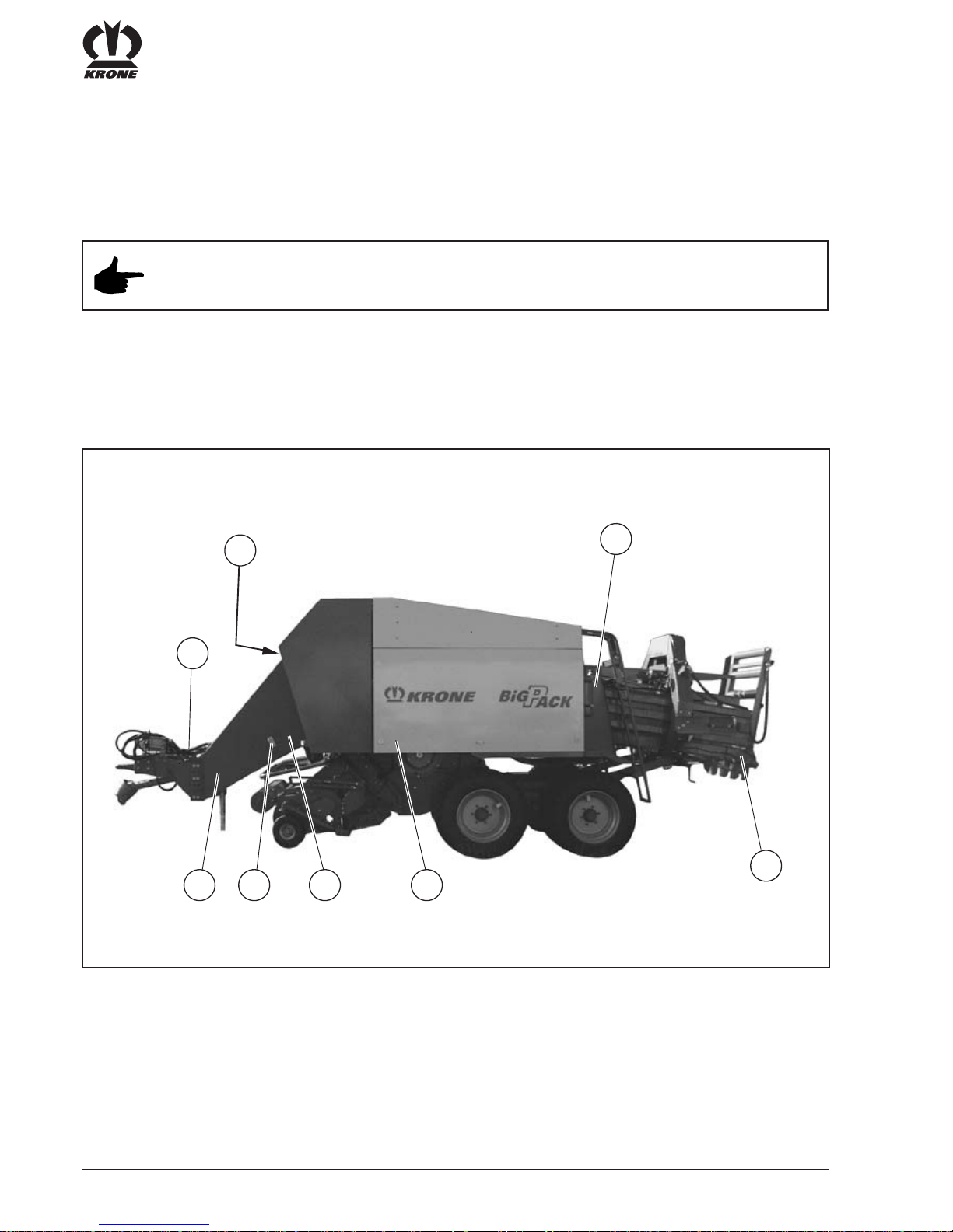
9. Height-adjustable drawbar
10. Wide-angle PTO shaft with overload
protection and free-wheeling
11. Twine box
12. Manual release of knotter and knotter shaft lock
13. Fire extinguisher
14. Wheel chocks
15. Electronic control valve
1. Mechanical flywheel holding brake
2. On-board computer
3. Bale length adjustment
4. Crank for parking brake
5. Twine control and tensioning device
6. Pick-up with feeler wheel
7. Holding-down device
8. Tool tray
2. 4 Overview of the Big Pack baler with tandem axle (Left-hand side)
BP800022
15
11
8

II - 9
Safety
1. Knotting area
2. Hydraulic oil storage tank
3. Parking support
4. Holder for fast-action couplings and plugs
5. XC cutting system drive
6. Pick-up hydraulics shut-off valve
7. Twine brake in the twine box
8. Bale chute
2.5 Overview of the Big Pack baler with tandem axle (right-hand side)
BP800023
8
3
2
5
4
6
7
1

II - 10
Safety
2. 6 Mode of operation of the BIG PACK XC baler
- VFS conveyor system
1211
16
9876
BP-VFS-004
1514
321
4 5 10
16
14
15 13
16
10987654
3
2
1
1211
13
16

II - 11
Safety
The feed packers (4) fill the conveyor channel The crop
is collected in the conveyor channel by the work of the
feed packers. The filling level in the conveyor channel is
sensed by sensing rakes (16). When a certain filling level
is reached, the sensing rake is swung back and the
feeder packer takes over the further transport of the crop
into the baling channel.
The baling ram force is controlled electronically by
hydraulic cylinders (9) on the baling channel flaps. Once
the set pack length is reached, the knotter mechanism is
released by the star wheel projecting into the baling
channel. The Big Pack 890 is equipped with 4
and Big Pack 1270 and 1290 with 6 knotters (7). The
big bales are unloaded through a bale chute (10).
The crop is pressed by the baling ram (6) in the baling
channel to form a highly compacted big bale. The length
and naturally also the density of the big bales can be
adjusted continuously.
Thus big bales can be generated according to widely
differing requirements.
As drive the BIG PACK baler requires a tractor
with a power of 65 kW.
The BIG PACK baler is hooked into the hitch coupling or
the swinging drawbar. So that the Big Pack baler can
work horizontally, the drawbar is provided with height
adjustment.
The drive of the BIG PACK is through a PTO shaft,
which transmits the torque coming from the tractor
through a flywheel (11) to a bevel spur gearbox (12).
The maximum input speed of 1000 rpm must not be
exceeded, because this could cause the machine to be
damaged.
The PTO shaft is equipped at the tractor end with a
wide-angle joint. The operating instructions intended for
the PTO shaft are located on the PTO shaft.
Before the Big Pack baler is started up
the operating instructions of the PTO shaft should
also be read. Shortening the PTO shaft and any
repair and maintenance work are discussed here.
The 2 m (2.4 m) wide pick-up (2) picks up the crop
cleanly. A height-adjustable baffle plate (1) ensures
trouble-free pick-up and helps to avoid clogging. The
crop is conveyed by 2 worm conveyors (3), located
on the left and right side of the pick-up, to the
feed packer drum (13) or to the cutter rotor (14) and
blades (15).
The pick-up can be raised and lowered by the tractor
hydraulics. So that an optimum pick-up height can be
achieved for the pick-up, the feeler wheels of the pick-up
are adjustable in height.

II - 12
Safety
III - 1
Preparations on the Big Pack Baler
3. Preparations on the Big Pack Baler
3.1 Special safety instructions
• Special caution is required when mounting and detaching the Big Pack baler on and
from the tractor. No one may stay between the tractor and Big Pack baler. After
successful coupling turn off the engine and pull out the ignition key. Apply the
flywheel brake.
• In service, maintenance, adjustment and repair work on the Big Pack baler always switch
the PTO shaft off, turn off the engine and pull out the ignition key.
• Put the Big Pack baler into operation only if all protective devices are attached and in
protective position.
• The Big Pack baler may be operated with a maximum PTO shaft speed of 1000
rpm.
• Only the PTO shaft specified by the manufacturer with corresponding overload coupling and
free motion may be used.
• Mounting and detaching the PTO shaft only with the PTO disengaged, the engine turned off
and the ignition key withdrawn.
• Run hoses and connection cables so that they are not subject to tension when cornering or
come into contact with the tractor wheels.
• Check hydraulic hose lines regularly and replace them in the case of damage or
ageing.
• When connecting and removing the hydraulic hoses to and from the tractor hydraulics take
care that the hydraulics are pressureless both on the tractor side and the machine side.
3.2 Adjusting the drawbar height
• Secure the Big Pack baler against rolling away with wheel chocks and by applying the
parking brake.
• Use suitable supporting blocks for supporting the Big Pack baler.
• There is a risk of crushing one’s feet when cranking down the parking support.
Before starting the adjustment set the Big Pack baler on the parking support and uncouple the
tractor.
The drawbar can be adjusted optionally for top or
bottom attachment. Both in the “top attachment”
position and in the “bottom attachment” position the
Big Pack baler can still be adapted in height to the
hitching height of the tractor (hitch or swinging
drawbar).
To guarantee optimum working, the Big Pack baler
must be hitched horizontally. The top edge of the
twine box serves as reference edge in this case.
III - 2
Preparations on the Big Pack Baler
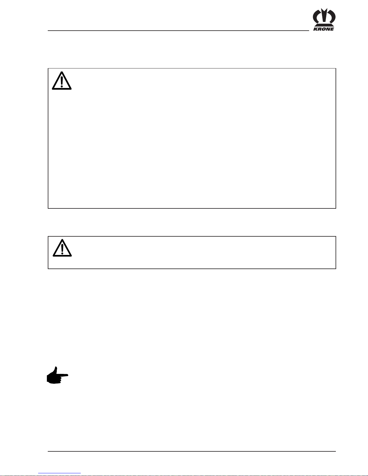
Setting the hitching height
For the adjustment of the drawbar height the hitch (2)
can be adjusted in height by loosening the screws (1). If
this is not sufficient the side parts (4) can be adjusted in
height by additionally loosening the screws (3).
For adjusting to bottom attachment the two side parts (4)
are turned round.
Tightening torques see section 8.2.
3.3 Adapting the main PTO shaft
• Before pushing the PTO shaft onto the PTO of the tractor, disengage the PTO, turn off the
engine and pull out the ignition key. Apply the flywheel brake.
• Secure the tractor and Big Pack baler against unintentionally rolling away.
• In the cornering movements required for adapting the length of the PTO shaft no one may
stand between the baler and the tractor.
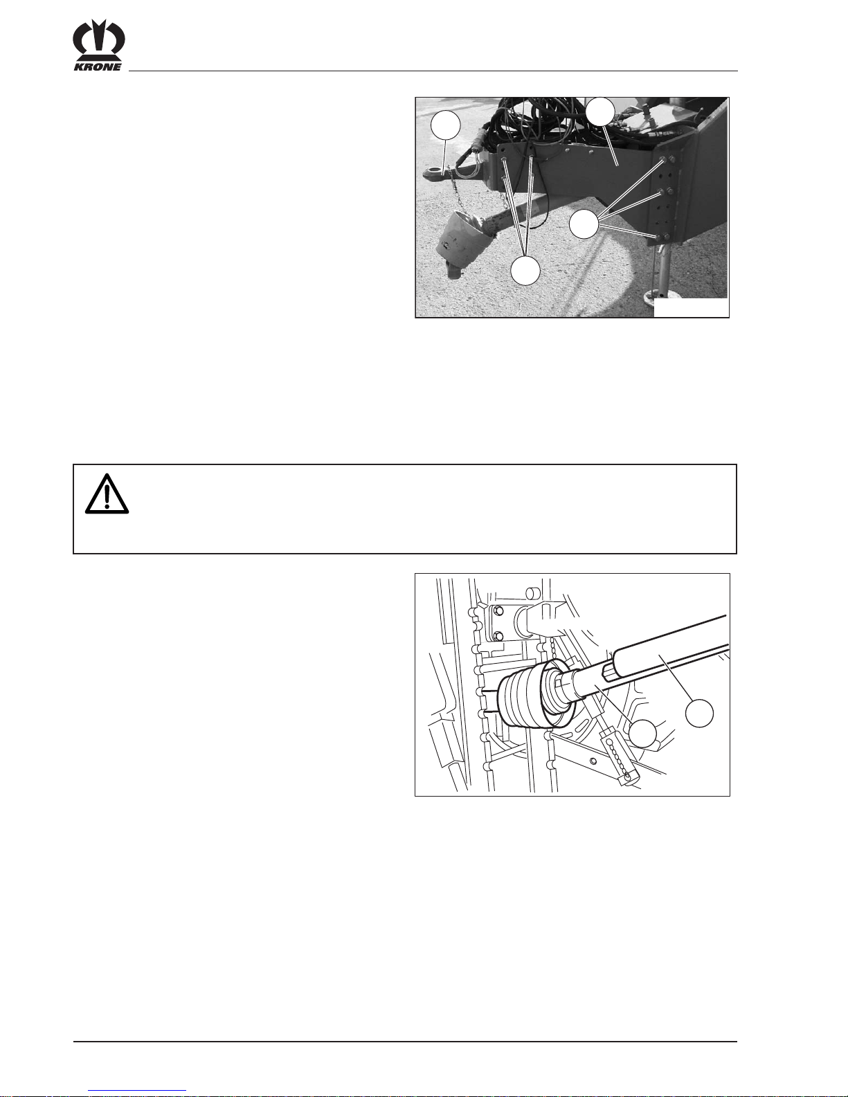
To adapt the length of the PTO shaft hitch the Big Pack
baler onto the tractor. The shortest position of the PTO
shaft is reached in close cornering.
For measuring pull the PTO shaft apart and push one half
each (1) and (2) onto the baler and the tractor. Please
refer to the operating instructions of the PTO shaft
manufacturer for the exact procedure for adapting the
length.
1
3
4
BP800001
2
BP800002
1
2

III - 3
Preparations on the Big Pack Baler
3.4 Commissioning the Big Pack baler
3.4.1General
Main drive
A bevel spur gear serves as main drive. The necessary
torque is transmitted through the PTO shaft and a
generously dimensioned flywheel. The maximum drive
speed must not exceed 1000 rpm. The PTO shaft is
protected at the machine end by a friction clutch (1).
There is a cam-controlled gearbox or a shear screw on
the back of the flywheel.
As soon as the clutch responds, stop
the machine, disengage the PTO with
out delay and brake the flywheel. After
the fault is rectified, the cam-controlled
gearbox engages again automatically.
In the version with shear screw, turn the
flywheel by hand after standstill of the
machine until the shear screw can be
changed.
Feed packer drum drive
The drive of the feed packer drum is located on
the left side of the machine. The gearbox is
protected by a spring-loaded ratchet clutch or by a
shear screw.
As soon as the ratchet clutch responds,
stop the machine and disengage the
PTO without delay. Do not brake the
flywheel. After the fault is rectified, the
ratchet clutch automatically starts to
work.
In the version with shear screw, turn the
flywheel by hand after standstill of the
machine until the shear screw can be
changed.
BP380-7-009
1
BP800003
BPXC0026
BPXC0027

III - 4
Preparations on the Big Pack Baler
Pick-up drive for XC cutting system
The torque is transmitted through a star ratchet to the
drive chain of the pick-up from the output of the lower
angular gear of the cutting system.
Knotter shaft drive
The knotter shaft is driven by an angular gear. A PTO
shaft transmits the torque through the knotter gear to the
knotter shaft.
Pick-up drive through gear
(without XC cutting system)
The torque is transmitted by an angular gear from above
through a PTO shaft with overload protection (star
ratchet) downwards onto an angular gear.
XC Cutting system drive
The cutting rotor is driven by an upper angular gear. An
intermediate shaft transmits the torque through a camcontrolled gearbox onto a lower angular gear.
As soon as the cam-controlled gearbox
responds, stop the machine and reduce
the speed until the machine has cleared
itself again. The cam-controlled gearbox
now automatically resumes its work.
BP380-7-011
BPXC0035
BPXC0034
BPXC0028

III - 5
Preparations on the Big Pack Baler
3.4.2Hitching the Big Pack baler onto the tractor
• When you back the tractor up to the Big Pack baler, no one may stand between the tractor
and baler.
• Observe the maximum supporting and tensile load of the hitch on the tractor.
Hitch and secure the Big Pack baler according to the
regulations on the hitch of the tractor.
According to the national requirements, a revolving hitch
or a hitch is available.
Spacer sleeve for the drawbar for bottom attachment
Swinging drawbars frequently have a locking bolt smaller
in diameter than a hitch. For this reason a spacer sleeve
(2), which can be inserted in the hitch (1) as required. is
enclosed with the Big Pack balers with bottom
attachment.
BP800005
Coupling
Pick-up drive through chains
(without XC cutting system)
The drive is by an upper sprocket. This sprocket is
provided with a star ratchet or protected by a shear
screw according to version. The torque is now
transmitted through a chain onto an intermediate shaft.
The pick-up is driven by a chain from this intermediate
shaft.
BP380-7-014
2
1
BPXC0029
III - 6
Preparations on the Big Pack Baler
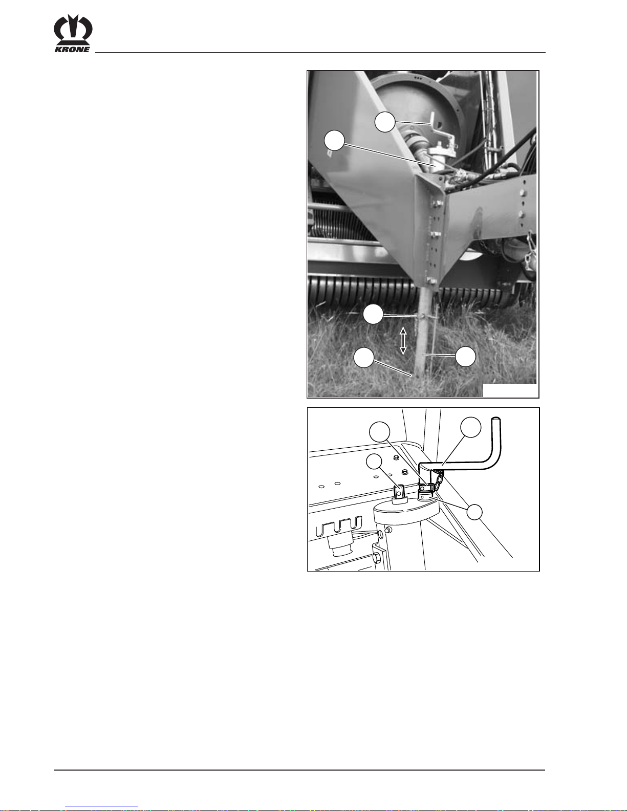
Crank on the parking support
The crank (2) can be plugged on in two positions, (a) and
(b), on the head of the parking support.
Position a) Direct gear ratio 1:1 for fast adjustment up
and down of the jack
Position b) Step-down gear for cranking up and down if
the Big Pack baler rests on the support
base.
Jack
As soon as the Big Pack baler is hitched up, take the
load off the support base (3) by turning the crank (1).
Withdraw the locking bolt (5) on the lower part of the
parking support (2), push in the parking support and
secure it in position (4) with the bolt. Crank the parking
support up fully.
BP380-7-016
b
2
a
1
1
2
3
5
4
BP800006

III - 7
Preparations on the Big Pack Baler
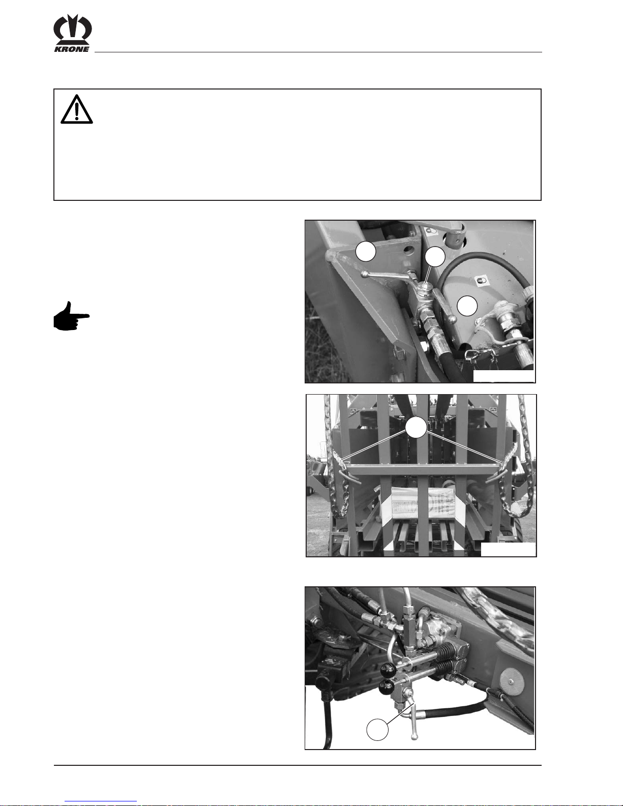
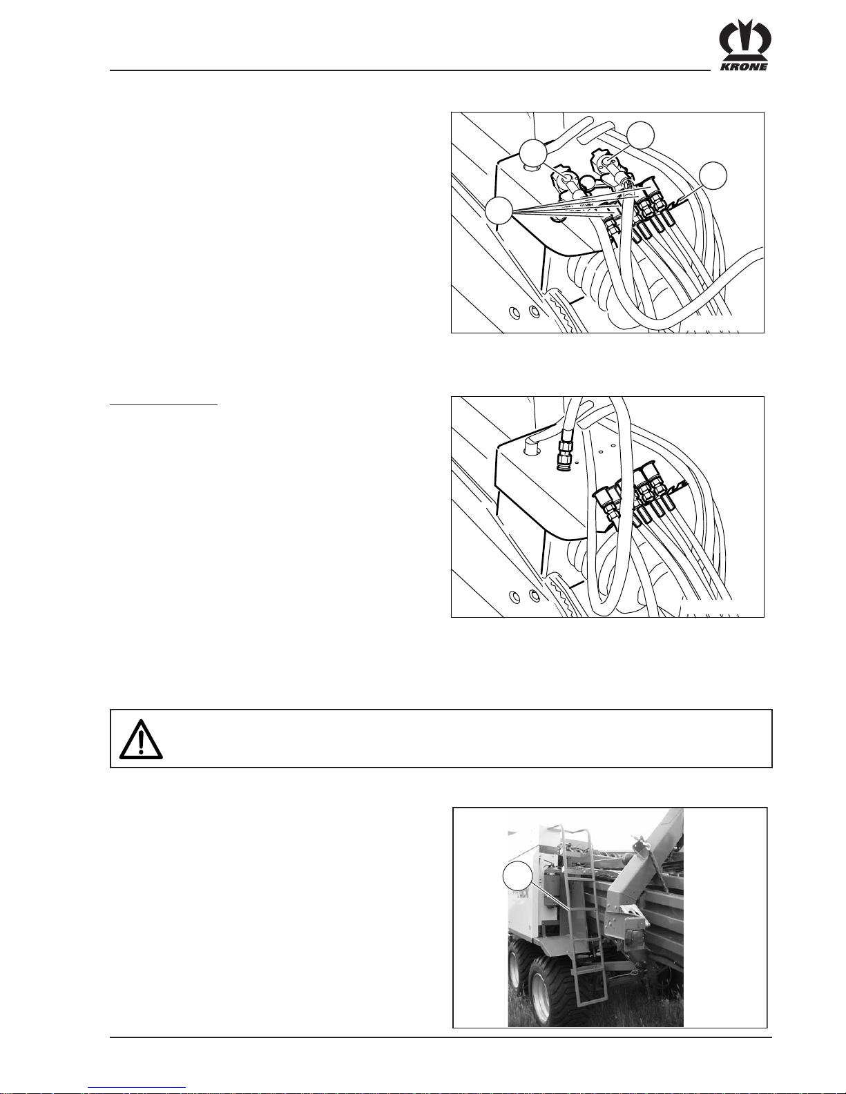
Hydraulic connections
According to version, a different number of hydraulic
control valves is required on the tractor for the Big Pack
baler. The protective caps of the hydraulic hoses (1)
placed in the stowage (2) are colour-coded. Perfect
identification of the necessary control valve is guaranteed
by this:
see Chapter 1 “Hydraulic connections on the tractor”
BPXC0053
2
1
3
Version with Comfort electronics
Load-sensing connection
The Comfort hydraulic system is load-sensing-capable.
The advantage of using it with tractors equipped for it is
the lower power requirement because the oil does not
heat up as much.
The oil supply comes through the Power-Beyond of the
tractor hydraulics for use of the Load-Sensing-System.
The message line must be connected between the
message connection (LS) on the control block and the
message connection of the tractor. The message line (3)
(NW 12, blue protective cap) on the Big Pack with
Comfort hydraulics is located directly under the pick-up
connection on the front of the drawbar.
The hydraulic system screw (1) on the
control block must be unscrewed when
the message line is connected.
Adjusting the hydraulic system
The Comfort hydraulic system must be adjusted on the
tractor. It is designed for continuous circulation. The
adjustment is made by adjusting the hydraulic system
screw on the electromagnetic valve block.
The block is located at the front left under the front hood
next to the electronics box.
The adjustment depends on the hydraulic
system of the tractor and must be made
while there is no pressure in the Big Pack!
III - 8
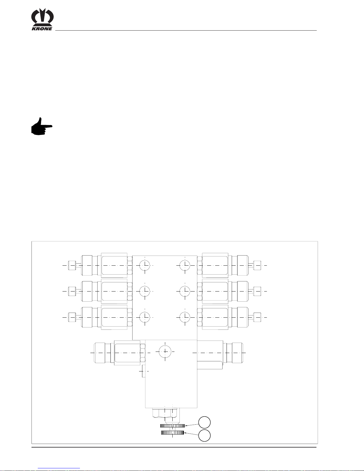
Preparations on the Big Pack Baler
B1
B2
B3
A1
A2
A3
P
LS
T
1
2
The system screw (1) is held in place with a counter nut
(2) and must first be loosened for the system screw to
be adjusted. Then the counter nut can be tightened on
the housing again (by hand).
Screw the system screw (1) as far as it will go for:
Tractors with normal hydraulic system (constant pump)
Tractors with LS pump and message line that is not
connected
This adjustment is set when the unit
leaves the factory.
Unscrew the system screw (1) as far as it will go for:
– Tractors with a closed hydraulic system (for example
John Deere)
– Tractors with LS pump and message line that is
connected

III - 9
Preparations on the Big Pack Baler
Compressed air connections for compressed
air brake
Snap the coloured coupling heads of the compressed air
hoses (1) into the correspondingly coloured couplings on
the tractor.
First let the yellow coupling head snap in
and then the red coupling head.
Uncoupling is in reverse order.
Hydraulic brake
A hydraulic brake is provided for certain export versions.
In this version a hydraulic brake valve on the tractor is
required.
BP380-7-018
1

III - 10
Preparations on the Big Pack Baler
Mounting the PTO shaft
Machine end
• see section 3.3
Tractor end
• Take the PTO shaft out from the retaining chain (1).
• With the engine turned off and the ignition key
withdrawn, push the PTO shaft onto the tractor PTO
and secure it.
• Secure the PTO shaft guard against turning by hooking
in the locking chain (2).
• Make sure that the locking device of
the PTO shaft has snapped into place
after mounting.
• Use only the PTO shaft delivered by
the factory.
Before pushing the PTO shaft onto the tractor PTO, absolutely brake the flywheel with the
holding brake.
PTO shaft
BP800007
1
2
BP800060
a
b
1
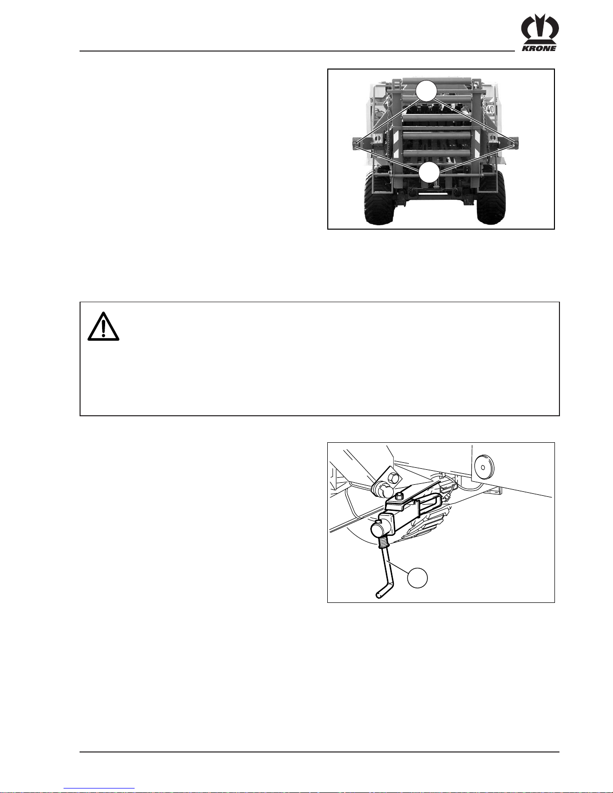
Flywheel holding brake
The belt brake is located at the left side of the machine on
the drawbar.
To brake the flywheel move the brake lever (1) on the
flywheel from position (a) into position (b). The flywheel is
now braked.
Caution! Before engaging the PTO release
the holding brake.

III - 11
Preparations on the Big Pack Baler
As soon as the plug of the continuous
current supply is plugged in and the
control and display unit is switched on
and there is no twine in the needles, the
acoustic signal of the twine control
sounds.
The Big Pack baler is equipped with an on-board
hydraulic pump. The storage tank (2) is located at the
drawbar. Check the oil level prior to every start-up with
the dipstick (1).
3.4.3On-Board Hydraulic System
• Repair work on the hydraulic system may be performed only by trained skilled personnel.
• Liquids escaping under high pressure can penetrate through the skin and cause severe
injuries! Go to a doctor immediately in the case of injuries! Danger of infection!
Parking brake
The crank (1) of the parking brake is located at the left
side of the Big Pack baler under the baling channel.
Before hitching the machine must be secured by the
parking brake against unintentional rolling away.
Electrical connection cables
The Big Pack baler requires a voltage source for the
power supply of the on-board computer. A socket for
installation on the tractor is part of the scope of supply.
Plug in and secure the connection cables in the
corresponding sockets on the baler.
Socket 1: Connection cable between on-board
computer and control console on the
tractor. Remove the protective cap before
plugging in.
Socket 2: Power supply of the on-board computer.
Socket 3: 7-pin standard socket for lighting.
BP380-7-022
1
2
BP800009
1
3
BPXC0011
2
1
III - 12
Preparations on the Big Pack Baler
In the version with hydraulic operation make sure that
the interlock is active (see the section “Hydraulically
folding bale chute with rollers”)
3.4.4Road travel
• Travelling on public roads is allowed only with empty baling channel and bale chute
folded in.
• The maximum speed is 40 km/h / 50 km/h (65 km/h).
• Riding on the Big Pack baler is not permitted.
• The traffic safety of the Big Pack baler, especially the lighting, locked protective covers and
twine box flaps, raised and secure pick-up must be checked and guaranteed.
• Before starting ensure perfect sight conditions on and around the tractor as well as towards
the Big Pack baler.
Bale chute
To bring the bale chute into the transport position, the
unfolded chute must be folded up and secured with the
retaining chains (4).
Pick-up
Raise the pick-up and secure it against lowering at the
shut-off valve (1). The lever, located at the left front
machine side at the drawbar, must be moved from
position (a) to position (b).
In machines with wide pick-up (special
equipment), the feeler wheels must be
swung into the transport position and
secured.
1
BP800010
a
b
BP800065
3
BPXC0041
4
III - 13
Preparations on the Big Pack Baler
Lighting
Connect the lighting system to the tractor electrical
system. Check the function of the tail lights (2) and the
reflectors (1) and clean these. The same applies for the
yellow reflectors attached on the sides of the Big Pack
baler and the front white clearance lights.
3.4.5Detaching the Big Pack baler
• Park the Big Pack baler only on level and firm ground. If the Big Pack baler is parked on
soft ground, enlarge the base area of the parking support.
• Secure the Big Pack baler against rolling away with wheel chocks and by applying the
parking brake.
• Take care when cranking down the parking support. There is danger of crushing your feet!
• Before uncoupling the hydraulic hoses, make the hydraulic system on the tractor and
machine side pressureless.
• Remove the PTO shaft only with the PTO disengaged and the engine turned off and the
ignition key withdrawn. Apply the flywheel brake.
Wheel chocks and parking brake
Apply the parking brake of the Big Pack baler with the
crank (1).
BP380-7-022
1
BPXC0036
1
2

III - 14
Preparations on the Big Pack Baler
Parking support and PTO shaft
The wheel chocks (2) are located at the rear on the right
and left next to the baling channel. Place the wheel
chocks in front of and behind the tyres. The machine is
secured against rolling away by this.
Slightly crank down the cranked up parking support (4)
with the crank (1). Pull out the bolt (2) and extend the
lower part of the parking support. Secure with the bolt. If
the ground is soft, enlarge the footprint of the support
base (3) by placing a wooden plank underneath.
Top attachment
Pull off the PTO shaft (5) and place it in the retaining
chain (6).
5
3
BP800013
2
6
1
4
BPXC0021
2
III - 15
Preparations on the Big Pack Baler
3.4.6 Ladder
• Climb on the ladder only with PTO shaft switched off, engine turned off and ignition key
withdrawn.
• Riding on the ladder is not permitted.
There is a ladder (1) on the left side of the machine at the
rear next to the baling channel that can be used for
maintenance work on the knotting mechanism.
Couple the compressed air hoses (1) and (2) into the
corresponding holders on the top of the drawbars.
Place the hydraulic hoses (3) in the holders (4).
Compressed air and hydraulic hoses
BP800014
1
For hydraulic brake
Plug the hose for the hydraulic brake onto the adapter.
BP380-7-030
4
2
1
3
BP380-7-017

III - 16
Preparations on the Big Pack Baler
3.4.7Fire extinguisher
A fire extinguisher (1) is installed on the left side of the
machine next to the baling channel.
Please have the fire extinguisher
registered. Only in this way is it
guaranteed that the inspections due in
each case are performed.
3.4.8Moving without connected compressed air brake
If the hoses of the compressed air brake are not
connected to a brake system, then the Big Pack baler
cannot be driven as a matter of course.
If a minimum pressure of 4 bar is available in the storage
tank (2) of the brake system of the Big Pack baler, then
the brake can be released by pressing the push button
(1) on the release valve into the position (a). The release
valve is located to the front on the right under the large
front hood. As soon as the hoses are again connected to
a compressed air brake system, the push button is
pushed back automatically into its starting position (b).
If the air pressure in the storage tank (2) has dropped
below 4 bar, the still available residual pressure must
also be let off by operating the drain valve (3). Only now
can the Big Pack baler be moved.
Secure the machine against rolling away
before operating the release valve or
letting off the air pressure from the
storage tank.
BP380-7-034
3
2
a
b
1
1
BPXC0037
1

IV - 1
Medium / Comfort control unit
4. Control unit
(Medium / Comfort)
4.1 General description
The electronics system consists of the distributor (1),
which contains the on-board computer, and the control
panel (2), which serves to display information and
operate the machine.
Distributor:
Position: on the left front of the machine under the front
cover.
Function: controlling the machine.
4.2 Attaching
Electrical power supply: Connect the power cable (12 V)
on the tractor side and machine
side on the 3-prong power
socket (DIN 9680). The power
socket on the machine side is
on the front metal cover. (a)
Control panel: can be connected in the socket
on the front metal cover with the
cable included with delivery (b).
The cable is connected to (3) on
the control panel.
Make certain that the
terminating connector is
connected on the control panel
(4). Otherwise the control panel
will not run without errors.
2
3
4
BPXC0038
a
b
BPXC0056
1

IV - 2
Medium / Comfort control unit
4.4 Operational readiness
After you have turned the unit on, the connection from
the control panel to the on-board computer is set up.
If it is not possible to establish a connection, the
following screen appears:
Once the connection to the control panel is set up, the
Manual mode basic screen as described below appears
after a brief wait. Then you can switch to the Automatic
mode basic screen:
BP890_0001
4.3 Control panel
Description of the buttons:
Emergency off button
On/Off switch
(always use the Emergency off
button)
- Buttons for menu control
Open/close menu
, ,
Buttons for icons displayed
above (softkeys)
, , ,
Buttons for icons displayed to the left
(softkeys)
Switching on:
- Unlock the Emergency off button (turn it to the left
until it pops up. You will then be able to see a green
mark under the red cap).
- If there are not yet any graphics to be seen on the
terminal, press and hold the button with I/O marking
for about 3 seconds.
Switching off:
- Should always be performed with the red Emergency
off button.
BP890_0031

IV - 3
Medium / Comfort control unit
4.4.1 Manual mode basic screen
a: Current PTO speed in RPM
b: The current daily bale counter (here counter 1); the
cut or uncut bale counter is automatically displayed,
depending on whether cutting is currently in
progress.
c: Current force of pressure as a % (100 % = max.)
d: The currently set target bale channel flap pressure in
bar. You can raise or lower the target pressure with
the arrow keys on the right.
e: Direction of motion display (arrow left/right from the
display). 1-3 arrows can be displayed on the left or
right side of the display each. The more arrows are
displayed, the more forcefully you need to steer in
the direction indicated. If no arrow is displayed, the
driving direction is correct and will result in optimally
shaped bales.
f: Target bale channel flap pressure as an arrow to the
left and right of the actual bale channel flap pressure
display.
g: The current actual bale channel flap pressure as a
bar diagram.
h: The current actual bale channel flap pressure in bar.
i: Softkey for switching between Automatic and
Manual operating modes and displaying which mode
is currently activated (for buttons located
underneath).
Press : Switches to Automatic mode.
Info: Softkey displays the current function.
Automatic mode
Manual mode
Here: Display of manual mode:
The pressure is assigned by the user. The pressure
builds up immediately when the PTO is running and
the machine is stopped. The pressure on the
pressure gauge hardly fluctuates at all.
Caution: If the pressure is set too high, the machine
could be subjected to a mechanical overload that
could result in destroying it. To avoid this, the bale
channel flap pressure should be reduced to a noncritical value just before an overload. After a few
seconds, it is possible to return to the pressure set
by the user.
Caution: In the event of an overload, it is absolutely
essential to reduce the target bale channel flap
pressure.
aa
g
f
e
d
c
b
h
m
n
o
BP890_0002
k
j
i
l

IV - 4
Medium / Comfort control unit
Manual mode basic screen (continued)
j: Softkey for additional headlight for buttons
underneath (Comfort version only).
Press : Headlight on
Press : Headlight off
Info: Softkey shows the current lighting status.
Headlight on
Headlight off
k: Softkey for bale ejector for buttons underneath
(Comfort version only):
Press : Extend the bale ejector.
Press : Retract the bale ejector.
Press once briefly: Automatic bale ejector
(several bale ejector strokes are performed
automatically).
Info: Softkey displays current function.
Standard
Extend the bale ejector.
Retract the bale ejector.
l: Softkey to raise/lower the lift blade bar for buttons
underneath (Comfort version only; medium
version displays the status of the blades if they
are present , ):
Press : Lift blade bar.
Press : Lower blade bar.
Info: Softkey displays the current function or the
current status.
Blade bar is currently being lowered.
Blade bar is currently being raised.
Cutting is currently in progress
(blade bar above and blades are folded in).
Cutting is not currently in progress
(blade bar down and/or blades are
not folded in).
m: The currently pending alarm as an alarm number (only
appears if an alarm is pending, see Section 4.13).
If .. is displayed in addition to the alarm number,
there are other alarms as well.
n: Appears as long as the bale channel flaps are
released. If the PTO is turning, the icon flashes
(Comfort version only).
o: Appears briefly if a plunger has been made (there is
an audio signal at the same time if it has been
activated by the user).
aa
g
f
e
d
c
b
h
m
n
o
BP890_0002
k
j
i
l

IV - 5
Medium / Comfort control unit
4.4.2 Automatic mode basic screen
c: The current bale channel flap pressure in bar
d: The currently set target force of pressure as a %
(100% = max.). You can raise or lower the target
force with the arrow keys on the right.
f: The target force of pressure as an arrow to the left
and right of the actual force of pressure display.
g: The current actual force of pressure as a bar dia-
gram.
h: The current actual force of pressure as a %.
i: Softkey for switching between Automatic and
Manual operating mode and display of which mode
is currently activated (for buttons located
underneath).
Press : Switching into and out of Manual
mode.
Info: Softkey displays current function.
Automatic mode
Manual mode
Here: Automatic mode display:
The pressure can be adjusted automatically based
on the plunger force that is measured.
The pressure on the pressure gauge may
fluctuate significantly. The control system will
only change its value if the packer is supplying
fodder to the plunger.
a
g
f
e
d
c
b
h
k
j
m
BP890_0003
l
i
125
64%
64%
For a description, see the Manual mode basic
screen, Section 4.4.1.
Differences:

IV - 6
Medium / Comfort control unit
4.4.3 Buttons on the machine
The Comfort version has a few buttons located externally
on the machine that can be used to perform functions on
the machine.
1. There are two buttons on the front left of the machine
on the front side of the twine box with the following
functions:
Lift blade bar.
Lower blade bar.
2. There are 4 buttons on the rear left of the machine
with the following functions:
Raise bale chute.
Lower bale chute.
Move bale ejector forward.
Move bale ejector backward.
BP890_0004
BP890_0005

IV - 7
Medium / Comfort control unit
4.4.4 Description of the baling process
Case 1: Bale channel is empty
The Manual mode basic screen always appears at the
beginning of the baling process. The bale channel must
first be filled to a pressure of about 50 bar there to
prevent the bale channel flaps from bending out of shape.
When the bale channel is filled, the pressure must be set
high enough so that the bales will be as solid as desired.
To always achieve the same solidity of bales
automatically with materials of different properties (for
example with differing moisture content of materials on
the same field), you should then switch into Automatic
mode. The program will then use the bale solidity that
was previously reached from Manual mode. The contact
pressure of the bale channel flaps is now controlled
automatically by the on-board computer so that the
selected force of pressure is achieved. As the material
becomes moister, it becomes more difficult to compress
the bales. Because of this, the bale channel flap
pressure is reduced somewhat. As the material becomes
drier, the bale channel flap
pressure is increased again. Therefore, the pressure on
the pressure gauge may fluctuate significantly, even
though the bale quality and solidity will remain the same.
Info: The force of pressure is recorded by two sensors
on the inside of the front frame section. Then it is
amplified and sent to the on-board computer. The
on-board computer evaluates the signals and then
controls the pressure of the hydraulic cylinders of
the bale channel flaps. The signals are also used
on the control panel for the direction of motion
display. The greater the difference between the
measured forces on the left and right sensors, the
more arrows will be shown in the display.
Case 2: Bale channel is full
Exactly like Case 1, but with the following difference:
1. If you will be baling in Automatic mode, you can
switch into Automatic mode immediately after the
machine starts. The last target force to be used will
be used again in this case, i.e. you can continue
baling with the same settings after turning the
machine off and back on.
The force of pressure setting should not
have been adjusted after the control
system is turned on in manual mode,
because the control system then forgets
the last settings from Automatic mode.
2. If you will be baling in Manual mode, the force of
pressure should be adjusted to the desired value
immediately after the control system is started.

IV - 8
Medium / Comfort control unit
4.5 Menu guidance
You can use the - buttons or the menu button
underneath them to the left of the control panel to
expand a menu bar on the left side of the control panel. It
can then be used to make settings for additional
functions on the machine.
The menu bar can be collapsed again with the menu
button .
Control panel display
BP890_0031
Basic screen with expanded menu bar
BP890_0032

IV - 9
Medium / Comfort control unit
Overview of menu guidance:
The menu windows and their hierarchical arrangement
are displayed:
a: Basic menu
F1: Settings -> Switch to b (see diagram)
F2: Counter
F3: Open / close bale channel flap
F4: Service -> Switch to c (see diagram)
b: Settings
F1: Activate/deactivate knotter signal
F2: Adjust the sensitivity of the direction display
F3:
F4:
c: Service
F1: Diagnostics -> Switch to d (see diagram)
F2: Krone service (protected area)
F3: Info:
F4: Control panel
d: Diagnostics
F1:
F2: Sensor test -> Switch to f (see diagram)
F3: Actuator test -> Switch to g (see diagram)
F4: Current alarms
e: Control panel
F1:
F2:
F3:
F4: Contract -> Switch to h (see diagram)
f: Sensor test
F1: Automatic sensor test
F2: Manual sensor test
F3:
F4:
g: Actuator test
F1: Automatic actuator test
F2: Manual actuator test
F3:
F4:
h: Contrast
a
b
c
d
e
f
g
h
BP890_0006

IV - 10
Medium / Comfort control unit
Softkeys: Operation with button just to the right or
underneath the icons.
Previous counter (counter image is moved down and
the previous counter is inserted on the top).
Following counter (counter image is moved up and
the following counter is inserted on the bottom).
Activation of the counter surrounded by frame (see
h). Only possible with daily bale counters. Bale
counter icon is surrounded in bold after activation
(see i).
Deletion of the counter surrounded by frame (see h).
Exit this screen and return to the basic screen.
a: The counters for uncut bales are displayed
underneath.
b: The counters for cut bales are displayed underneath.
Display only works if the machine is equipped
with MultiCut!
c: Total hours of operation counter (cannot be deleted).
d: Total bales counter (cannot be deleted).
e: Total bale counter 1 (can be deleted).
f: Total bale counter 2 (can be deleted).
g: Daily bale counter 1 (can be deleted).
h: The counter marked by the frame can be deleted with
the softkey . The daily bale counter marked by the
frame can be activated with the softkey .
i: The bale counter icon of the activated bale counter is
surrounded by a thick frame.
The next counter screen to be displayed is the previous
counter screen after you have clicked 3 times . The
sequentially numbered daily bale counters move from the
bottom up (a). The activated bale counter (b) moves upward
along with them. The wide frame (h) that is used to activate
or delete the bale counter remains in the middle of the
display.
a
b
c
d
e
f
g
h
i
BP890_0008
a
b
h
BP890_0009
4.6 Counters
You can reach the counter screen in the following
manner:
In the Manual or Automatic basic screen, press the F2
key on the control panel. The basic menu appears.
The counter screen appears after you press the F2 key.

IV - 11
Medium / Comfort control unit
4.7 Opening and closing the bale
channel flaps
Softkeys:
Operation with the key directly under the icons
Activation of the knotter signal
Deactivation of the knotter signal
Saving the modified setting
Exit this screen and return to the basic
screen
The current status is displayed as an icon:
Knotter signal activated
Knotter signal deactivated
4.8 Activate/deactivate knotter
signal
Activation/deactivation of an audio signal when a knot
has been completed.
BP890_0011
The Open / close the bale channel flaps function is only
available with operation in the Comfort version. It works
as follows:
In the Manual or Automatic basic screen, press the F3
key on the control panel. The basic menu appears.
If the following icon
is displayed in the menu, the
bale channel flaps will be released after you press F3.
If the following icon
is displayed in the menu, the
bale channel flaps will be closed after you press F3.
Then the basic screen appears again.
You can go to the appropriate screen in the following
manner:
In the Manual or Automatic basic screen, press the F1
key on the control panel.
The basic menu appears.
Press the F1 key: The following menu appears
Settings
Press the F1 key: The following menu appears:
Activate/deactivate knotter signal

IV - 12
Medium / Comfort control unit
4.9 Adjusting the sensitivity of the
direction display
BP890_0012
You can go to the appropriate screen in the following
manner:
In the Manual or Automatic basic screen, press the F1
key on the control panel. The basic menu appears.
Press the F1 key: The following menu appears
Settings
Press the F2 key: The following menu appears
Adjust sensitivity of direction
display
Adjust the sensitivity of the direction display.
=> the more sensitive, the stronger the motion
indications in the form of arrows.
Softkeys:
Operation with the key directly under the icons
Lower sensitivity
Higher sensitivity
Save the modified setting
Exit this screen and return to the
basic screen
The current sensitivity is displayed as a bar in the middle
graphic. The higher the bar, the greater the sensitivity of
the display.

IV - 13
Medium / Comfort control unit
4.10 Sensor test
The sensor test is used to adjust and test the sensors
installed on the machine.
The PTO must not be turning during the
sensor test.
You can go to the appropriate screen in the following
manner:
In the Manual or Automatic basic screen, press the F4
key on the control panel. The basic menu appears.
Press the F4 key: The Service menu appears.
Press the F1 key: The Diagnostics menu appears.
Press the F2 key: The Sensor test menu appears.
Press the F1 key: The Automatic sensor test screen
appears
or
Press the F2 key: The Manual sensor test screen
appears

IV - 14
Medium / Comfort control unit
4.10.1 Automatic sensor test
All sensors are checked for errors. This includes errors
such as broken cable, short circuit or defective sensor.
There is no check to ensure that the setting of the
sensors is correct for the automatic test. This must be
performed in the Manual sensor test.
If defective sensors are detected, they will be displayed
one under the other on the left side. The sensor with the
frame around it is the sensor currently being tested. The
current status of the sensor appears next to state:
Possible states:
state: 0: Not alive (no iron)
1: Alive (iron)
Broken cable
Short circuit
Softkeys:
Previous sensor
Following sensor
Exit this screen and return to the
basic screen
If no defective sensors have been detected, the following
screen appears.
BP890_0015
BP890_0016
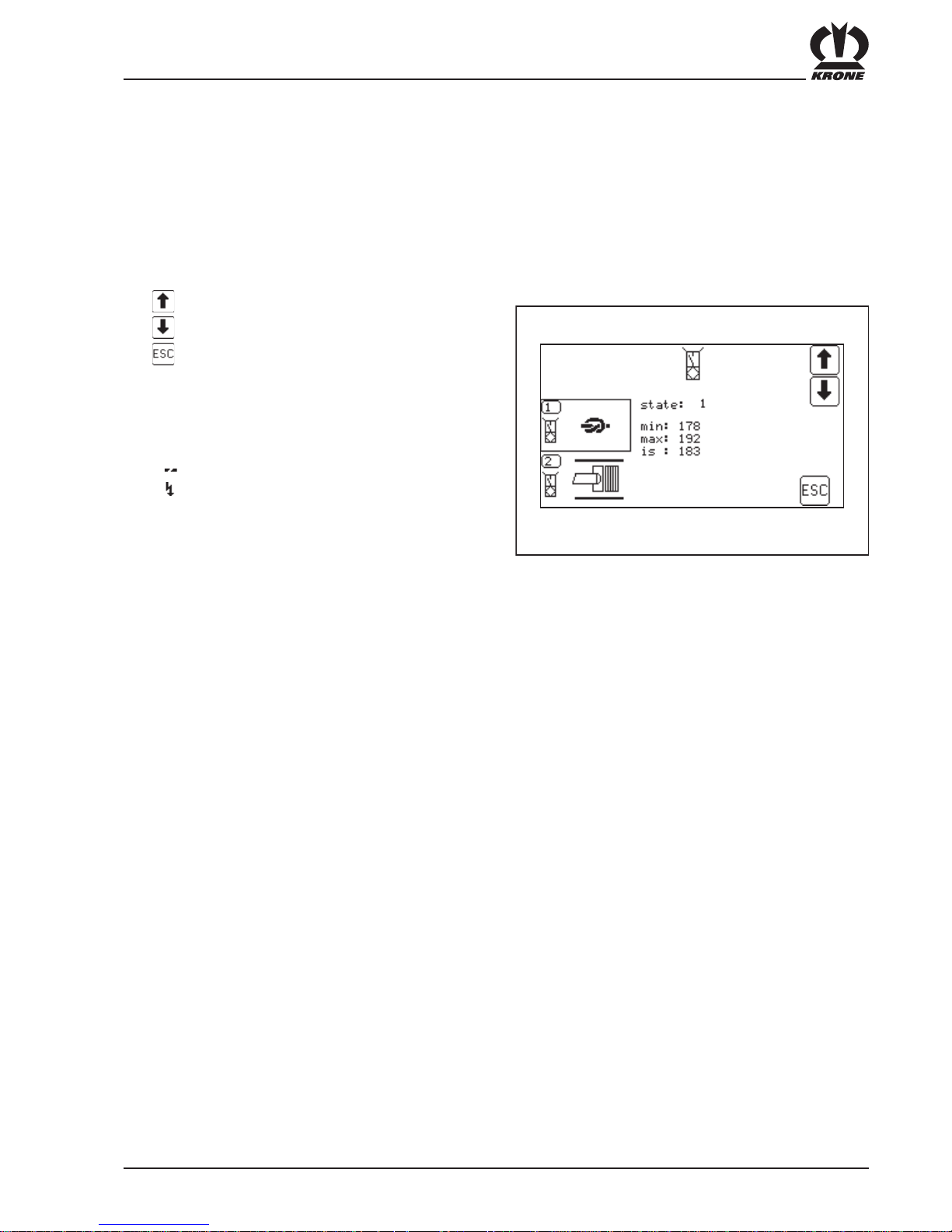
IV - 15
Medium / Comfort control unit
4.10.2 Manual sensor test
In the manual sensor test, the sensors are checked for
errors. In addition, the sensor type can be correctly
adjusted in the manual sensor test. There is no
guarantee the machine is working correctly until after the
sensors have been adjusted.
Icon with the frame around it on the left side: Sensor
currently being tested.
Previous sensor
Following sensor
Exit this screen and return to the
basic screen
Screen for Namur sensors:
state: 0: Not alive (no iron)
1: Alive (iron)
Broken cable
Short circuit
min. Minimum setting value
max. Maximum setting value
is: The current setting value (if the current setting
value falls between min and max, an audio signal
will be heard).
The distance from the sensors to the metal must be
adjusted so that with the sensors alive (metal in front of
the sensor) the actual value falls between the min and
the max value. If the setting is correct, an audio signal
will be heard.
BP890_0017
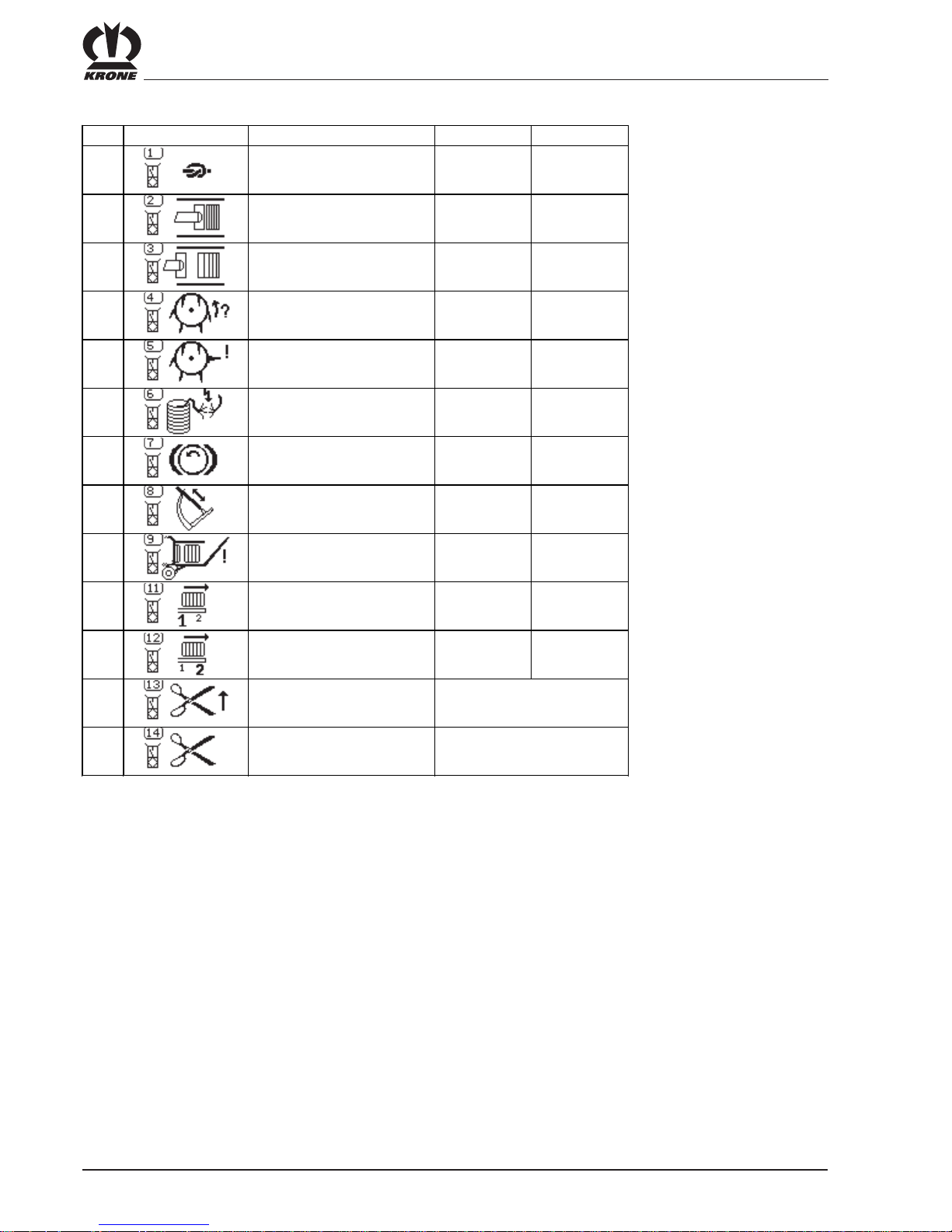
IV - 16
Medium / Comfort control unit
Possible sensors are:
No. Se nsor symbol Description Comfort Me dium
1 Knotter m oni t ori ng x x
2 Measuring x x
3 Calibration x x
4 Packe r monitori ng x x
5 Packer feed x x
6 Twine monit ori ng x x
7 Flywheel brake x x
8 Needle c onnect i ng rod x x
9 Bal e chute x x
11 Bal e ejector front x
12 Bal e ejector rear x
13 Bl ade bar up
14 Bl ade acti ve
x (i f blade i s present )
x (i f blade i s present )
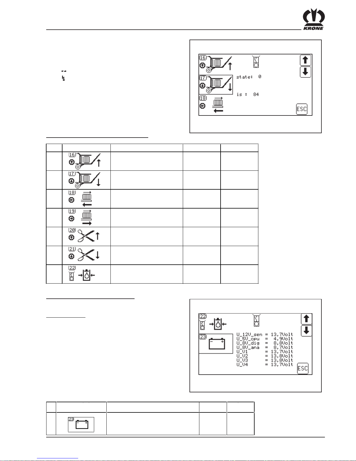
IV - 17
Medium / Comfort control unit
Screen for buttons and pressure sensor:
state: 0: Not pressed
1: Pressed
Broken cable
Short circuit
is: The current actual value (for information only)
BP890_0018
Possible buttons / pressure sensors are:
Screen for power supply voltages:
Nominal voltage: U_12V_sen: 12 - 14.5V
U_5V_cpu: 4.5 -5.5V
U_8V_dig: 8.5 -9.1V
U_8V_ana: 8.5 -9.1V
U_V1: 12 -14.5V
U_V2: 12 -14.5V
U_V3: 12 -14.5V
U_V4: 12 - 14.5 V
BP890_0019
No. Symbol Description Comfort Medium
16 B ale chute up but ton x
17 B ale chute down but t o n x
18 B ale ejec tor in button x
19 B ale ejec tor out butt on x
20 B l a de bar up butt on x
21 B la de bar down button x
22 P ressur e sensor x x
Nr Symbol Beschreibung Komfort Medium
23
Spannung x x
N° Symbol Description Comfort Medium
Voltage

IV - 18
Medium / Comfort control unit
4.11 Actuator test
1. The PTO must not be turning during
the actuator test.
2. Actuators are controlled during the
actuator test. This may result in the
machine performing unexpected
actions. Because of this, this test
must be conducted from a safe
location outside the working area of
the machine parts affected by the
actuators.
The actuator test is used to test the actuators installed
on the machine.
You can go to the appropriate screen in the following
manner:
In the Manual or Automatic basic screen, press the F4
key on the control panel. The basic menu appears.
Press the F4 key: The Service menu appears.
Press the F1 key: The Diagnostics menu appears.
Press the F3 key: The Actuator test menu appears.
Press the F1 key: The Automatic actuator test
screen appears.
or
Press the F2 key: The Manual actuator test screen
appears.

IV - 19
Medium / Comfort control unit
4.11.1 Automatic actuator test
All actuators are checked for errors. The test will last for
a few seconds.
If defective actuators are detected, they will be displayed
one under the other on the left side. The actuator
surrounded by the frame is the currently displayed
actuator. The status of the actuator at the time of the
test appears next to state:
Possible states:
state: : General actuator error
No electrical power supply,
fuse is probably defective.
Softkeys:
Previous actuator
Following actuator
Exit this screen and return to the basic screen.
If no defective actuators have been detected, the
following screen appears.
BP890_0021
BP890_0022

IV - 20
Medium / Comfort control unit
4.11.2 Manual actuator test
An actuator cannot be tested unless current is being
supplied to it. Because of this, the actuators must be
briefly activated manually in the manual test to make it
possible to detect any errors in the actuator system.
Text surrounded by a frame at the left of the screen:
Actuator currently being tested
Previous sensor
Following sensor
Exit this screen and return to the basic screen.
Screen for digital actuators such as valves, etc.:
You can tell whether the actuator is ON or OFF by
which of the following softkeys can be activated.
Turn on the actuator
Turn off the actuator
state: Errors are only displayed if the actuator
is turned on =>
0: Actuator off
1: Actuator on
: General actuator error
No electrical power supply,
fuse is probably defective.
BP890_0023

IV - 21
Medium / Comfort control unit
Possible digital actuators are:
Screen for analogue actuators such as pressure
control valves, etc.:
A current (in mA) can be adjusted using PWM (parts per
thousand).
With PWM = 500 the current should be between 500 mA
and 3000 mA (depends on the valve used).
Increase PWM
Decrease PWM
state: 0: Actuator off
1: Actuator on
No electrical power supply,
fuse is probably defective.
Possible analogue actuators are:
BP890_0024
Nr Symbol Beschreibung Komfort Medium
1
Druckregelventil x x
N° Symbol Description Comfort Medium
Control valves
No. Symbol Description Comfort Medium
1 Knotter cleaning valve x x
2 Bale channel flap rele as e valve x
3 Blade ba r valve Y07 x
4 Blade ba r valve Y08 x
5 Bale ejec tor val ve Y05 x
6 Bale ejec tor val ve Y06 x
7 Bale chut e val ve Y03 x
8 Bale chut e val ve Y04 x
9 Main valve Y01 x
10 Main valve Y 02 x
11 Seat valve Y10 x
13 Additiona l hea dl ight x

IV - 22
Medium / Comfort control unit
4.12 Currently pending alarm
BP890_0025
4.13 Krone Service
You can reach the Krone service area by entering a
password.
6.14 Info
You can reach the appropriate screen in the following
manner:
In the Manual or Automatic basic screen, press the F4
key on the control panel. The basic menu appears.
Press the F4 key: The Service menu appears.
Press the F3 key: The Info screen appears.
SW Jobrechner: SW version of job computer
SW Terminal: SW version of control panel
Exit this screen and return to the
basic screen
BP890_0027
Top left on the screen: x/y => Alarm x of y alarms
currently pending (in the example shown below: 1/3:
Alarm 1 of 3 alarms currently pending is shown).
Previous alarm
Following alarm
Exit this screen and return to the
basic screen
In the middle field surrounded with a frame: The current
alarm as a graphic, with the alarm number at the top left
in the field with the frame around it. Alarm numbers are
listed in Section 4.14.
You can go to the appropriate screen in the following
manner:
In the Manual or Automatic basic screen, press the F4
key on the control panel. The basic menu appears.
Press the F4 key: The Service menu appears.
Press the F1 key: The Diagnostics menu appears.
Press the F4 key: The screen for displaying the
currently pending alarm appears.

IV - 23
Medium / Comfort control unit
4.15 Contrast
4.16 Alarm message window
If an alarm is detected on the machine, the following
alarm window is used to notify the user. The window is
superimposed over the previous screen. At the same
time, there is an audio signal. The alarm number is
shown at the top left in the alarm message window.
Section 4.17 contains a list of possible alarms.
The alarm is acknowledged/reset and the
window closes; the audio signal stops.
Audio signal stops
Caution: All functions in the screen that is covered
over are still active. If the basic screen had
softkeys at the position and also,
they are deactivated for the time being.
You can increase or reduce the contrast of the display
by pressing the Up arrow or Down arrow button. After
the control panel has been turned off and back on, the
contrast returns to its default value.
BP890_0029
You can reach the appropriate menu in the following
manner:
In the Manual or Automatic basic screen, press the F4
key on the control panel. The basic menu appears.
Press the F4 key: The Service menu appears.
Press the F4 key: The Contrast menu appears.
Press the F4 key: The Adjust contrast menu
appears.
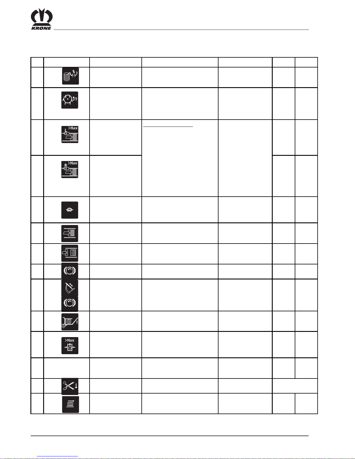
IV - 24
Medium / Comfort control unit
4.17 Alarm messages
No. Alarm Description Possible cause Remedy Comfort Medium
0
Twine monitoring - twine to rn
- end of twine
- check twine and twine
tensioner x x
1
Packer monitoring - blockage in feed area of the
packe r
- stop the travel drive
immediately
- PTO speed must be
reduced until the
blockage is eliminated
xx
2
Left sensor pressure
force exceeded
Pressure force exceeded
If the machine could be subject to a
mechani c al overload because the
pressure is too high, the bale
channel flap pressure is lowered to a
non-critical value just before the
overload. The amount of reduction
depends on the material being
baled. The amount of reduction will
be less for straw than for silage.
The following measures
must be taken:
1. In manual mode:
Lower the pressure
2. In automatic mode:
- if the baling channel is
filling in heavily on one
side: Fill in the channel
even ly
- if it happens quite
frequently:
Reduce the pressure
force setting somewhat
xx
3
Pressure force
exceeded for right
sensor
x
x
4
Knotter monitoring
Knotter is not functioning properly
- Sensor is set incorrectly
- knotter + check knotter
triggering
- Knotter monitoring
sensor adjust correctly
xx
5
Me asurement
monitoring
Measurement sensor defective or
set incorrectly
- adjust sensor correctly
xx
6
Calibration monitoring Calibration sensor defective or set
incorrectly
- adjust sensor correctly
xx
7
Flywheel brake Flywheel brake app li ed - relea se brake
xx
8
Needle connecting rod Shear screw cracked - replace the shear screw
- check needles
- check swivel range of
the needle
- check twine guiding
xx
9
Bale chute Bale chute up and PTO turning - lower bale chute
xx
10
Baling pressure
exceeded
Error on pressure control valve
- Pressure sensor may be defective
- stop PTO
- pressure control valve
open check for blockage
xx
11
Error Diagmode PTO is turning upon entry into sensor
or actuator diagnostics or during
diagnostics
- stop PTO immediately
- perform diagnostics
with PTO stopped
xx
12
Blade bar down - Blade bar is down during b ali ng - raise blade bar x
(if blade is present)
13
Bale ejector The bale channel flap pressure is too
high
- loosen the bale channel
flap! x
Error
Diagmode

IV - 25
Medium / Comfort control unit
No. Alarm Description Possible cause Remedy Com fort Medium
14
Under-voltage - tractor battery defective
- tractor light machine too we ak
- 12 V - power supply cable too thin
on tractor side or not connected
dire ctly with the ba tte ry
- Connect Krone
connection cable directly
to battery x x
15
Over-voltage tra ctor light machine defect ive Che ck light machin e
xx
101
Cord monitoring sensor sensor or supply line defective - perform sensor test
- check sensor + supply
line for damage
xx
102
Packer monitoring sensor sensor or supply line defective - perform sensor test
- check sensor + supply
line for damage
xx
103
Packer feed sensor sensor or supply line defective - perform sensor test
- check sensor + supply
line for damage
xx
104
Upp er blade bar sensor sensor or supply line defective - perform sensor test
- check sensor + supply
line for damage
x
(if blad e is present )
105
Blade sensor active sensor or supply line defective - perform sensor test
- check sensor + supply
line for damage
x
(if blad e is present )
106
Knotter monitoring sensor sensor or supply line defective - perform sensor test
- check sensor + supply
line for damage
xx
107
Meas uring force sensor sen sor or supply line defective - perform sensor te st
- check sensor + supply
line for damage
xx
108
Calibrat ion force sensor s ensor or supply line defective - perform sensor test
- check sensor + supply
line for damage
xx
109
Flywheel brake sensor sensor or supply line defective - perform sensor test
- check sensor + supply
line for damage
x
x
110
Needle connecting rod
sensor
sensor or supply line defective - perform sensor test
- check sensor + supply
line for damage
xx
111
Bale chute sensor sensor or supply line defective - perform sen sor test
- check sensor + supply
line for damage
xx
112
Right force sensor sensor, measurem ent amplifier or
supply line defective
- check sensor + supply
line for damage
xx
113
Left force sensor sen sor, measurement amplifier or
supply line defective
- check sensor + supply
line for damage
xx
114
Hy draulic pressure sensor sen sor or supply line defective - perform sensor test
- check sensor + supply
line for damage
xx
116
Forward bale ejector
sensor
sensor or supply line defective - perform sensor test
- check sensor + supply
line for damage
x

IV - 26
Medium / Comfort control unit
No. Alarm D e sc rip tion Possible ca us e Remed y Com fort Medium
117
Rear bale ejector sensor Sensor or supply line
defective
- perform sensor test
- check sensor + supply
line for damage
x
119
Bale chute up key Key or supply line defective - perform sensor test
- check key+ supply line for
damage
x
120
Bale chute down key Key or supply line defective - perform sensor test
- check key + supply line
for damage
x
121
Bale ejector out key Key or supply line defective - perform sensor test
- check key + supply line
for damage
x
122
Bale ejector in key Key or supply line defective - perform sensor test
- check key + supply line
for damage
x
123
Blade bar up key Key or supply line defective - perform sensor test
- check key + supply line
for damage
x
124
Blade bar down key Key or supply line defective - perform sensor test
- check key + supply line
for damage
x

IV - 27
Medium / Comfort control unit
4.18 Circuit diagrams
4.18.1 Medium control unit
-F1
F1
F2
F3
F4
0
I
Bu chs e
8-pol.
Stecker
8-pol.
Stecker Buchse
rt,nc
br,nc
ws, 12V
bl, CAN_H
rs, GND
gr, CAN_L
br,nc
gb,nc gb,nc
gn,12V
gn,12V
-Display
15/30
+KB1X7-1X6Bb
31
15/30
31
+KB1X6-1X6Ba
3
+KB1X5-1X5a
456172
15/ 3 0
+KB1X6-1X6a
12V DIN-Connect or
31
3
+KB1X4-1X5b
456172
15/30
31
+K B1X4-1 X6b
ABCDEFGHJKLMNPRS
+K B1X4 -1X4b
ABCDEFGHJKLMNPRS
-1X4a
26.1
-X1 00
7.1
-X1 00
19.1
-X1 00
8.1
-X100
20.1
-X100
1.1
-X100
3.1
-X100
22.1
-X100
21.1
-X100
SS_5 V
/2.2
+12 VEFU
/2.3
CAN 1-L
/2.6
GND
/2.4
CAN 1-H
/2.5
+12VE
/2.2
0V
/2.3
CAN 2-H
/2.6
CAN 2-L
/2.6
2: brown
7: blue
3: green
6: pin k
1: white
4: yellow
5: gre y
grey
yellow
white
pink
green
blue
brown
Battery ground
CONTRO L
CONTROL
Battery +12V
CONTROLTRACTOR
Drawbar
21.05.2003
1 2 3 4 5 6 7 8
Kloepper
06.03.2002Garmann
1 2 3 4 5 6 7 8
1/1 0
Standar d power supply
1
303 288-0
Krone-No.:
Person i. C. Location
NameDate
Dat e Plant
Repl. for Repl. byNorm
Sheet No.
Sh. of No.OriginState Modification
Insp.

IV - 28
Medium / Comfort control unit
SS_5V
/1.8
26.3
-X100
+12VE
/1.8
1.2
2.1
1.3
1.4
2.2
2.3
+12VEFU
/1.8,/3.1
7.2
-X100
0V
/1.8,/8.1
3.2
-X100
5.1
GND
/1.8,/3.1
8.2
-X100
+12VSEN
/6.1
9.1
-X100
GND_SEN
/3.1
11.1
123
15
29 3 0 31
16 1 73218
45
19
33 34
67
203521822
36 37
92310 11
24
38 39
25
12 13
26
40 41
271428
42
123
15
29 30 31
16 173218
45
19
33 34
67
203521822
36 37
92310 11
24
38 39
25
12 13
26
40 41
271428
42
X 2 X 1
EINGÄNGE
AUSGÄNGE
Ver sorgu ng
+12VE
+12VE
SS_5 V
+12V1
+12V2
+12V3
+12V4
+12VEFU
+12V1FU
+12V2FU
0V
0V
0V
0V
GND
GND
GND
+12V SEN
+12V SEN
GND_SEN
GND_SEN
GND_NAM
GND_NAM
+8VANA
+8VANA
GND_ANA
GND_ANA
CAN_1-H
CAN_1-H
CAN_1-L
CAN_1-L
TERMI_1
TERMI_1
CAN_2-H
CAN_2-H
CAN_2-L
CAN_2-L
TERMI_2
TERMI_2
RXD
TXD
CTS
GND über Sicherung
Versorgung LA_1 / Elektronik
Versorgung LA_1 / Elektronik
Schaltspannungseingang
Versorgung HB 1-4
Versorgung HB 5-8
Versorgung PW M_LA 5-8
Versorgung LA_2 und PWM_LA 1-4
+12VE über F8 (5A)
+12V1 über F13 (25A)
+12V2 über F6 (25A)
Mass e 12V Versorgung
Mass e 12V Versorgung
Mass e 12V Versorgung
Mass e 12V Versorgung
0V über F7 (30A) keine A us gänge
0V über F7 (30A) keine A us gänge
0V über F7 (30A) keine A us gänge
+12VE über Sicherung
+12VE über Sicherung
GND über Sicherung
GND über Sicherung
Analogspannung Multieingänge
Analogspannung Multieingänge
GND über Sicherung
GND über Sicherung
GND über Sicherung
Ver sorgu ng Se nsor en
Ver sorgu ng An alog sen soren
CAN 1
CAN 2
RS 232
Ver sorgu ng Dig ita lse nsor en
X1_41
X1_37
X2_37
X1_28
X1_01
X1_14
X2_15
X1_31
X1_42
X2_28
X1_15
X1_29
X2_29
X2_42
X1_09
X1_38
X2_38
X1_36
X2_09
X1_20
X2_02
X1_13
X2_41
X1_05
X2_21
X1_02
X2_11
X1_18
X2_39
X1_32
X2_25
X1_17
X2_40
X1_08
X2_12
X1_34
X2_13
X1_33
X2_36
X1_04
X1_19
X1_16
X2_10 MeasuringDIG _1 /4. 4
X2_17 Front bale ejectorDIG _2 /5. 5
X2_18 Blade activeDIG _3 /4. 3
X2_19 CalibrationDIG _4 /4. 5
X2_20 Bale chuteDI G _ 5 /5. 3
X2_22 Bale set-downDI G _6 /5. 4
X2_31 Packer supplyDIG_ 7 /4. 7
X2_32 Rear bale ejec torDIG _8 /5. 6
X2_33 Packer monitoringDIG _9 /4. 6
X1_07 Upper blade barDIG_10 /4.2
X1_10 Knotter monitoringDIG _11 /5.2
X1_11 Cord monitori ngDIG_12 /4.8
X1_12 Flywheel brak eDIG_13 /4.1
X1_35 Needle connecting rodDIG_14 /5.1
X2_03 Bale channel flap pressureMUL TI _1 /6.2
X2_05 MULTI_2
X2_07 For ce of pressure rightMUL TI _3 /6.4
X2_23 For ce of pressure leftMUL TI _4 /6.5
X1_03 Blade bar upMUL TI _5 /7.1
X1_06 Blade bar downMUL TI _6 /7.2
X1_21 Bale ejector outMU L TI_7 /7. 5
X1_27 Bale ejector inMU LT I_8 /7.4
X1_39 Bale chute upMUL TI _9 /7.7
X1_40 Bale chute downMULTI_10 /7.8
X2_16 For ce sensor s simula tionLA_1 / 6. 6
X2_27 Knotter cleaningLA _2 /1 0 .5
X2_35 Release bale channel flapPWM_LA _1 /9.7
X2_24 Blade barPWM_LA_2 /9.1
X2_30 Blade barPWM_LA_3 /9.2
X2_26 Bale chutePWM_LA_4 /9.5
X1_22 Bale chutePWM_LA_5 /9.6
X1_23 Main valve (ex tend)PWM_LA _6 /8.5
X1_26 Main valve (retract)PWM_L A_7 /8.6
X1_30 Seat valvePWM_LA_8 /8.4
X2_01 Control valveHBPWM _ 1 /8. 1
X2_04 Control valveHBPWM _ 2 /8. 2
X2_06 Elec tr . knot triggeringHBPWM_3 /10.3
X2_08 Knot cleaning 2HBPWM_4 /10.6
X2_34 Bale ejectorHB PW M _ 5 /9. 3
X2_14 Bale ejectorHB PW M _ 6 /9. 4
X1_24 Machine lightingHBPWM_7 /10.1
X1_25 HBPWM_8
-A1
GND_NAM
/4.1
14.1
-X100
16.1
CA N 1- H
/1.8,/3.1
20.2
-X100
CAN 1-L
/1.8,/3.1
19.2
19.3
CA N 2- H
/1.8,/3.1
22.2
-X100
CAN 2-L
/1.8,/3.1
21.2
21.3
RXD
/3.1
TXD
/3.1
CTS
/3.1
21.05.2003
1 2 3 4 5 6 7 8
Kloepper
07.03.2002Garmann
1 2 3 4 5 6 7 8
2/1 0
Job computer
2
303 288-0
Krone-No.:
Person i. C. Location
NameDate
Dat e Plant
Repl. for Repl. byNorm
Sheet No.
Sh. of No.OriginState Modification
Insp.

IV - 29
Medium / Comfort control unit
RXD
/2.7
CTS
/2.7
TXD
/2.7
GND_SEN
/2.4
CAN 2-H
/2.6
CAN 2-L
/2.6
CAN 1-H
/2.5
CAN 1-L
/2.6
GND
/2.4
+12VEFU
/2.3
7.3
-X1 00
+-
-1XSteck
12V plug receptacle
8.3
19.4
-X 100
20.3
13.1
SUB -D St ec ke r
162738495
-1XCAN1
21.4
-X100
22.3
13.2
SUB-D Stecker
162738495
-1XCAN2
SU B-D St ec ke r
162738495
-1XRS2 32
13.3
-X1 00
GND_SE N
/6.1
GND
/6.3
+12VEFU
/6.3
for laptop power sup ply ma x. 5 A
21.05.2003
1 2 3 4 5 6 7 8
Kloepper
22.04.2002Garmann
1 2 3 4 5 6 7 8
3/1 0
Interfa ces
3
303 288-0
Krone-No.:
Person i. C. Location
NameDate
Dat e Plant
Repl. for Repl. byNorm
Sheet No.
Sh. of No.OriginState Modification
Insp.
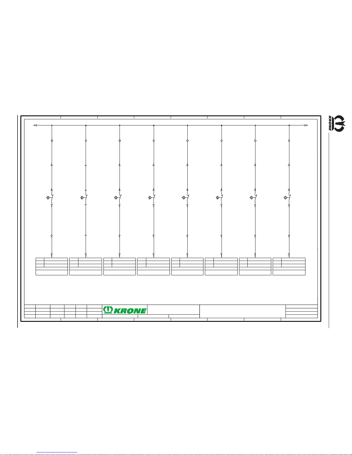
IV - 30
Medium / Comfort control unit
GND_NAM
/2.5
14.2
-X 100
1
-1X1a
1
+KB1X1-1X1b
1
+KB1X1-XB1a
1
2
+KB1X1-B1
Flywheel
2
+KB1X1-XB1a
2
+KB1X1-1X1b
2
-1X1a
12
-JR1X 1b
Anschl.
I / O
Modul
X1_12
-A1
/2.4
DIG_13
Flywheel brake
KMC 1
14.3
-X100
1
-1X 3a
1
+KB1 X3-1X3 b
1
+KB1 X3-X B2a
1
2
+KB1 X3-B 2
Up per blad e bar
2
+KB1 X3-X B2a
2
+KB1 X3-1X3 b
2
-1X 3a
7
-J R1X 1b
Anschl.
I / O
Modul
X1_07
-A1
/2.4
DIG_10
Upper blade bar
KMC 1
14.4
-X 100
3
-1X3a
3
+KB1X3-1X3b
1
+KB1X3-XB3a
1
2
+KB1X3-B3
Blad e active
2
+KB1X3-XB3a
4
+KB1X3-1X3b
4
-1X3a
18
-JR1X 2b
Anschl.
I / O
Modul
X2_18
-A1
/2.4
DIG _ 3
Blade active
KMC 1
15.1
-X100
3
-1X 1a
3
+KB1 X1-1X1 b
1
+KB 1X1- XB4a
1
2
+KB1 X1-B 4
Measurin g
2
+KB 1X1- XB4a
4
+KB1 X1-1X1 b
4
-1X 1a
10
-J R1X 2b
Anschl.
I / O
Modul
X2_10
-A1
/2.4
DIG_1
Measuring
KMC 1
15.2
-X100
5
-1X1a
5
+KB1X1-1X1b
1
+K B1X1- XB5a
1
2
+KB1X1-B5
Calibra tion
2
+K B1X1- XB5a
6
+KB1X1-1X1b
6
-1X1a
19
-JR1X 2b
Anschl.
I / O
Modul
X2_19
-A1
/2.4
DIG _ 4
Ca li br ati on
KMC 1
15.3
-X100
7
-1X 1a
7
+KB 1X1- 1X1b
1
+KB 1X1- XB6a
1
2
+KB1X1-B6
Packer monitoring
2
+KB 1X1- XB6a
8
+KB 1X1- 1X1b
8
-1X 1a
33
-JR1X2b
Anschl.
I / O
Modul
X2_33
-A1
/2.4
DIG_9
Pac k er m o ni t or i n g
KMC 1
15.4
-X 100
9
-1X1a
9
+KB1X1-1X1b
1
+KB1X1-XB7a
1
2
+KB1X1-B 7
Packer supply
2
+KB1X1-XB7a
10
+KB1X1-1X1b
10
-1X1a
31
-JR1X 2b
Anschl.
I / O
Modul
X2_31
-A1
/2.4
DIG _ 7
Packer supply
KMC 1
16.2
-X100
1
-1X 2a
1
+KB1 X2-1X2 b
1
+KB1 X2-X B8a
1
2
+KB1X2-B8
Cord monito ring
2
+KB1 X2-X B8a
2
+KB1 X2-1X2 b
2
-1X 2a
11
-J R1X 1b
Anschl.
I / O
Modul
X1_11
-A1
/2.4
DIG_12
Cord mo nito ring
KMC 1
GND_NAM
/5.1
21.05.2003
1 2 3 4 5 6 7 8
Kloepper
08.03.2002Garmann
1 2 3 4 5 6 7 8
4/1 0
Inputs
4
303 288-0
Krone-No.:
Person i. C. Location
NameDate
Dat e Plant
Repl. for Repl. byNorm
Sheet No.
Sh. of No.OriginState Modification
Insp.
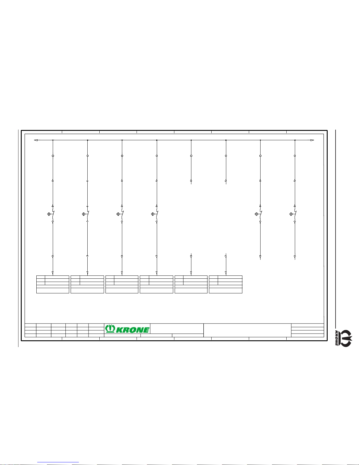
IV - 31
Medium / Comfort control unit
GND_NAM
/4.8
16.3
-X 100
3
-1X2a
3
+KB1X2-1X2b
1
+KB1X2-XB9a
1
2
+KB1X2-B9
eedl e connec ting r od
2
+KB1X2-XB9a
4
+KB1X2-1X2b
4
-1X2a
35
-JR1X 1b
Anschl.
I / O
Modul
X1_35
-A1
/2.4
DIG_14
Needle connecting rod
KMC 1
16.4
-X100
11
-1X 1a
11
+KB1 X1-1X1 b
1
+K B1X1- XB10 a
1
2
+KB1X1-B10
Knot ter moni tori ng
2
+K B1X1- XB10 a
12
+KB1 X1-1X1 b
12
-1X 1a
10
-J R1X 1b
Anschl.
I / O
Modul
X1_10
-A1
/2.4
DIG_11
Knotter monito ring
KMC 1
17.1
-X 100
5
-1X2a
5
+KB1X2-1X2b
1
+KB 1X2- XB11 a
1
2
+KB1 X2-B 11
Bale chute
2
+KB 1X2- XB11 a
6
+KB1X2-1X2b
6
-1X2a
20
-JR1X 2b
Anschl.
I / O
Modul
X2_20
-A1
/2.4
DIG _ 5
Bale chute
KMC 1
17.2
-X100
7
-1X 2a
7
+KB1 X2-1X2 b
1
+K B1X2 -XB1 2a
1
2
+KB1X2-B12
Bale set-down
2
+K B1X2 -XB1 2a
8
+KB1 X2-1X2 b
8
-1X 2a
22
-J R1X 2b
Anschl.
I / O
Modul
X2_22
-A1
/2.4
DIG_6
Bale se t-down
KMC 1
17.3
-X100
9
-1X2a
9
+KB1X2-1X2b
10
+KB1X2-1X2b
10
-1X2a
17
-JR1X 2b
Anschl.
I / O
Modul
X2_17
-A1
/2.4
DIG _ 2
Front bale e jector
KMC 1
17.4
-X100
11
-1X 2a
11
+KB 1X2- 1X2b
12
+KB 1X2- 1X2b
12
-1X 2a
32
-JR1X2b
Anschl.
I / O
Modul
X2_32
-A1
/2.4
DIG_8
Rear bale ejector
KMC 1
18.1
-X 100
13
-1X2a
13
+KB1X2-1X2b
1
+KB 1X2- XB15a
1
2
+KB1 X2- B15
St ar wh eel 1
2
+KB 1X2- XB15a
14
+KB1X2-1X2b
14
-1X2a
18.2
-X100
15
-1X 2a
15
+KB1 X2-1X2 b
1
+K B1X2- XB16 a
1
2
+KB1X2-B 16
Star wheel II
2
+K B1X2- XB16 a
16
+KB1 X2-1X2 b
16
-1X 2a
GND_NAM
Sensor star wheel 1 + 2 (fo r t est only)
21.05.2003
1 2 3 4 5 6 7 8
Kloepper
12.03.2002Garmann
1 2 3 4 5 6 7 8
5/1 0
Inputs
5
303 288-0
Krone-No.:
Person i. C. Location
NameDate
Dat e Plant
Repl. for Repl. byNorm
Sheet No.
Sh. of No.OriginState Modification
Insp.

IV - 32
Medium / Comfort control unit
+12 VSEN
/2.4
GND_SEN
/3.8
9.2
-X1 00
13
-1X1a
13
+KB1 X1-1X1 b
1
P
U
1+ 2-
3A
+KB1 X1-B 17
Bale channel flap pressure
11.2
14
14
2
+K B1X1- XB17 b
3
+KB 1X1- XB17b
15
+KB1X1-1X1b
15
-1X1a
3
-JR1X 2b
Anschl.
I / O
Modul
X2_03
-A1
/2.4
MULTI_1
Bale channel flap pressure
KMC 1
19
+K B1X1 -1X1 b
19
-1X1a
8.4
-X1 00
GND
/3.8
18
18
7.4
+12VEFU
/3.8
16
+KB1 X1-1X1 b
16
-1X1a
7
-JR 1X 2b
Anschl.
I / O
Modul
X2_07
-A1
/2. 4
MUL TI _3
Force of pressure right
KMC 1
17
+K B1X1 -1X1 b
17
-1X1a
23
-JR 1X 2b
Anschl.
I / O
Modu l
X2_23
-A1
/2.4
MUL TI _4
Force of pressure left
KMC 1
26
+K B1X1 -1X1 b
26
-1X1a
16
-JR1X2b
Anschl.
I / O
Modu l
X2_16
-A1
/2.4
LA_1
Force sensors simulation
KMC 1
1
+K B1X1 -XN1b
2 3 4 5
F
R
1
2
3
4
+Zug gli ed-B 19
Ri ght f orce sen sor
1
-XB 19a
F
T315mA
1
ON DIP
23 4
1
ON DIP
234
Poti
Poti
Schalter
+12V0VSign re
Sign li
+12V0V-Sign
+Sign
rechts links
+12V0V-Sig n
+Sign
1234
1234 1234
+Zugglie
d
2 3 4
F
R
1
2
3
4
+Zugglied-B18
Left for ce s enso r
1
-XB18a
2 3
+12VSEN
/7.1
GND_S EN
/7.1
4
brown
black
blue
white
brown
black
white
brown
grey
black
blue
white
blue
21.05.2003
1 2 3 4 5 6 7 8
Kloepper
07.03.2002Garmann
1 2 3 4 5 6 7 8
6/1 0
Force meas urement
6
303 288-0
Krone-No.:
Person i. C. Location
NameDate
Dat e Plant
Repl. for Repl. byNorm
Sheet No.
Sh. of No.OriginState Modification
Insp.

IV - 33
Medium / Comfort control unit
+12 VSEN
/6.8
GND_SEN
/6.8
11.3
-X100
5
-1X 3a
5
+KB1 X3-1X3 b
6
+KB1 X3-1X3 b
6
-1X 3a
3
-J R1X 1b
Anschl.
I / O
Modul
X1_03
-A1
/2.4
MULTI_5
Blade bar up
KMC 1
9.3
7
7
11.4
-X100
8
-1X3a
8
+KB1X3-1X3b
9
+KB1X3-1X3b
9
-1X3a
6
-JR1X 1b
Anschl.
I / O
Mo dul
X1_06
-A1
/2.4
MULTI_6
Blade bar down
KMC 1
9.4
10
10
12.1
-X100
17
-1X2a
17
+KB1X2-1X2b
18
+KB1X2-1X2b
18
-1X2a
27
-JR1X 1b
Anschl.
I / O
Modul
X1_27
-A1
/2.4
MULTI_8
Bale ejector in
KMC 1
10.1
19
19
12.2
-X100
20
-1X2a
20
+KB1X2-1X2b
21
+KB1X2-1X2b
21
-1X2a
21
-JR1X 1b
Anschl.
I / O
Modul
X1_21
-A1
/2.4
MULT I_7
Bale ejector out
KMC 1
10.2
22
22
12.3
-X 100
23
-1X2a
23
+KB1X2-1X2b
24
+KB1X2-1X2b
24
-1X2a
39
-JR1X 1b
Anschl.
I / O
Modul
X1_39
-A1
/2.4
MULTI_9
Bale chute up
KMC 1
10.3
25
25
12.4
-X1 00
26
-1X2a
26
+K B1X2 -1X2 b
27
+K B1X2 -1X2 b
27
-1X2a
40
-JR 1X 1b
Anschl.
I / O
Modu l
X1_40
-A1
/2.4
MULTI_10
Bale chute down
KMC 1
10.4
28
28
+12VSEN
GND_S EN
21.05.2003
1 2 3 4 5 6 7 8
Kloepper
12.03.2002Garmann
1 2 3 4 5 6 7 8
7/1 0
Manual control
7
303 288-0
Krone-No.:
Person i. C. Location
NameDate
Dat e Plant
Repl. for Repl. byNorm
Sheet No.
Sh. of No.OriginState Modification
Insp.

IV - 34
Medium / Comfort control unit
0V
/2.3
Anschl.
I / O
Modul
X2_01
-A1
/2.4
HBPWM_1
Control valv e
KMC 1
1
-JR1X 2b
29
-1X2a
29
+KB1X2-1X2b
1
+KB1 X2-X Y11b
1
2
-Y11
Control valve
2
+KB1 X2-X Y11b
Anschl.
I / O
Modul
X2_04
-A1
/2.4
HBPWM_2
Control valve
KMC 1
4
-J R1X 2b
30
-1X 2a
30
+KB1 X2-1X2 b
Anschl.
I / O
Modul
X1_30
-A1
/2.4
PWM_LA_8
Seat valve
KMC 1
30
-JR1X 1b
11
-1X3a
11
+KB1X3-1X3b
12
+KB1X3-1X3b
12
-1X3a
3.3
-X100
Anschl.
I / O
Modul
X1_23
-A1
/2.4
PWM_LA_6
Main v alve (extend)
KMC 1
23
-JR1X 1b
13
-1X3a
13
+KB1X3-1X3b
14
+KB1X3-1X3b
14
-1X3a
3.4
-X1 00
Anschl.
I / O
Modul
X1_26
-A1
/2.4
PWM_LA_7
Main v alve (retract)
KMC 1
26
-J R1X 1b
15
-1X 3a
15
+KB1 X3- 1X3b
16
+KB1 X3- 1X3b
16
-1X 3a
4.1
-X100
0V
/9.1
21.05.2003
1 2 3 4 5 6 7 8
Kloepper
12.03.2002Garmann
1 2 3 4 5 6 7 8
8/1 0
Outputs
8
303 288-0
Krone-No.:
Person i. C. Location
NameDate
Dat e Plant
Repl. for Repl. byNorm
Sheet No.
Sh. of No.OriginState Modification
Insp.

IV - 35
Medium / Comfort control unit
0V
/8.8
Anschl.
I / O
Modul
X2_24
-A1
/2.4
PWM_LA_2
Blade bar
KMC 1
24
-JR1X 2b
17
-1X3a
17
+KB1X3-1X3b
18
+KB1X3-1X3b
18
-1X3a
4.2
-X 100
Anschl.
I / O
Modul
X2_30
-A1
/2.4
PWM_LA_3
Blade bar
KMC 1
30
-J R1X 2b
19
-1X 3a
19
+KB1 X3-1X3 b
20
+KB1 X3-1X3 b
20
-1X 3a
4.3
-X100
Anschl.
I / O
Modul
X2_34
-A1
/2.4
HB PW M _ 5
Bale ejector
KMC 1
34
-JR1X 2b
21
-1X3a
21
+KB1X3-1X3b
22
+KB1X3-1X3b
22
-1X3a
4.4
-X 100
Anschl.
I / O
Modul
X2_14
-A1
/2.4
HBPWM_6
Bale ejector
KMC 1
14
-J R1X 2b
23
-1X 3a
23
+KB1 X3-1X3 b
24
+KB1 X3-1X3 b
24
-1X 3a
5.2
-X100
Anschl.
I / O
Modul
X2_26
-A1
/2.4
PWM_LA_4
Bale chute
KMC 1
26
-JR1X 2b
25
-1X3a
25
+KB1X3-1X3b
26
+KB1X3-1X3b
26
-1X3a
5.3
-X100
Anschl.
I / O
Modul
X1_22
-A1
/2.4
PWM_LA_5
Bal e chut e
KMC 1
22
-JR1X1b
27
-1X 3a
27
+KB 1X3- 1X3b
28
+KB 1X3- 1X3b
28
-1X 3a
5.4
-X100
Anschl.
I / O
Modul
X2_35
-A1
/2.4
PW M _ LA _1
Release bale channel flap
KMC 1
35
-JR1X 2b
29
-1X3a
29
+KB1X3-1X3b
30
+KB1X3-1X3b
30
-1X3a
6.1
-X 100
0V
/10.1
21.05.2003
1 2 3 4 5 6 7 8
Kloepper
08.03.2002Garmann
1 2 3 4 5 6 7 8
9/1 0
Outputs
9
303 288-0
Krone-No.:
Person i. C. Location
NameDate
Dat e Plant
Repl. for Repl. byNorm
Sheet No.
Sh. of No.OriginState Modification
Insp.

IV - 36
Medium / Comfort control unit
0V
/9.7
Anschl.
I / O
Modu l
X1_24
-A1
/2. 4
HBPW M_7
Ma chin e ligh ting
KMC 1
24
-JR 1X 1b
20
-1X1a
20
+KB1 X1-1X1 b
1
+KB1X1-XH1
1
2
-H1
Ma chine li ghti ng
2
+KB1X1-XH1
21
+KB1 X1-1X1 b
21
-1X1a
6.2
-X1 00
Anschl.
I / O
Modu l
X2_06
-A1
/2.4
HB PW M _3
Electr. kn ot triggering
KMC 1
6
-JR 1X 2b
22
-1X1a
22
+K B1X1 -1X1 b
1
+KB1X1-XKnoter
2
+KB1X1-XKnoter
23
+K B1X1 -1X1 b
23
-1X1a
6.3
-X1 00
Anschl.
I / O
Modul
X2_27
-A1
/2.4
LA_2
Knotter cleani ng
KMC 1
27
-JR1X 2b
24
-1X1a
24
+KB1X1-1X1b
1
+KB1X1-X20b
1
+KB1X1-X20a
1
+KB1X1-XY30
1
2
-Y30
Knotter cleaning
2
+KB1X1-XY30
2
+KB1X1-X20a
2
+KB1X1-X20b
25
+KB1X1-1X1b
25
-1X1a
6.4
-X1 00
3
3
0V
Anschl.
I / O
Modul
X2_08
-A1
/2.4
HBPWM_4
Knot cl eaning 2
KMC 1
8
-JR1X 2b
27
-1X1a
27
+KB1X1-1X1b
Reserve knotter tr iggering
21.05.2003
1 2 3 4 5 6 7 8
Kloepper
13.03.2002Garmann
1 2 3 4 5 6 7 8
10/ 1 0
Outputs for lighting / knotter blower
10
303 288-0
Krone-No.:
Person i. C. Location
NameDate
Dat e Plant
Repl. for Repl. byNorm
Sheet No.
Sh. of No.OriginState Modification
Insp.

IV - 37
Medium / Comfort control unit
4.18.2 Comfort control unit
-F1
F1
F2
F3
F4
0
I
Bu chs e
8-pol.
Stecker
8-pol.
Stecker Buchse
rt,nc
br,nc
ws, 12V
bl, CAN_H
rs, GND
gr, CAN_L
br,nc
gb,nc gb,nc
gn,12V
gn,12V
-Display
15/30
+KB1X7-1X6Bb
31
15/30
31
+KB1X6-1X6Ba
3
+KB1X5-1X5a
456172
15/ 3 0
+KB1X6-1X6a
12V DIN-Connect or
31
3
+KB1X4-1X5b
456172
15/30
31
+K B1X4-1 X6b
ABCDEFGHJKLMNPRS
+K B1X4 -1X4b
ABCDEFGHJKLMNPRS
-1X4a
26.1
-X1 00
7.1
-X1 00
19.1
-X1 00
8.1
-X100
20.1
-X100
1.1
-X100
3.1
-X100
22.1
-X100
21.1
-X100
SS_5 V
/2.2
+12 VEFU
/2.3
CAN 1-L
/2.6
GND
/2.4
CAN 1-H
/2.5
+12VE
/2.2
0V
/2.3
CAN 2-H
/2.6
CAN 2-L
/2.6
Battery ground
CONTRO L
brown
green
blue
TRACTOR
Drawbar
CONTROL
CONTROL
Battery +12V
pink
6: pin k
1: white
3: green
2: brown
7: blue
yellow
white
grey
4: yellow
5: gre y
21.05.2003
1 2 3 4 5 6 7 8
Kloepper
06.03.2002Garmann
1 2 3 4 5 6 7 8
BIG PACK 890/1270/1290 Comfort
1/1 0
Standar d power supply
1
303 289-0
Krone-No.:
Person i. C. Location
NameDate
Dat e Plant
Repl. for Repl. byNorm
Sheet No.
Sh. of No.OriginState Modification
Insp.

IV - 38
Medium / Comfort control unit
SS_5V
/1.8
26.3
-X100
+12VE
/1.8
1.2
2.1
1.3
1.4
2.2
2.3
+12VEFU
/1.8,/3.1
7.2
-X100
0V
/1.8,/8.1
3.2
-X100
5.1
GND
/1.8,/3.1
8.2
-X100
+12VSEN
/6.1
9.1
-X100
GND_SEN
/3.1
11.1
123
15
29 3 0 31
16 1 73218
45
19
33 34
67
203521822
36 37
92310 11
24
38 39
25
12 13
26
40 41
271428
42
123
15
29 30 31
16 173218
45
19
33 34
67
203521822
36 37
92310 11
24
38 39
25
12 13
26
40 41
271428
42
X 2 X 1
EINGÄNGE
AUSGÄNGE
Ver sorgu ng
+12VE
+12VE
SS_5 V
+12V1
+12V2
+12V3
+12V4
+12VEFU
+12V1FU
+12V2FU
0V
0V
0V
0V
GND
GND
GND
+12V SEN
+12V SEN
GND_SEN
GND_SEN
GND_NAM
GND_NAM
+8VANA
+8VANA
GND_ANA
GND_ANA
CAN_1-H
CAN_1-H
CAN_1-L
CAN_1-L
TERMI_1
TERMI_1
CAN_2-H
CAN_2-H
CAN_2-L
CAN_2-L
TERMI_2
TERMI_2
RXD
TXD
CTS
GND über Sicherung
Versorgung LA_1 / Elektronik
Versorgung LA_1 / Elektronik
Schaltspannungseingang
Versorgung HB 1-4
Versorgung HB 5-8
Versorgung PW M_LA 5-8
Versorgung LA_2 und PWM_LA 1-4
+12VE über F8 (5A)
+12V1 über F13 (25A)
+12V2 über F6 (25A)
Mass e 12V Versorgung
Mass e 12V Versorgung
Mass e 12V Versorgung
Mass e 12V Versorgung
0V über F7 (30A) keine A us gänge
0V über F7 (30A) keine A us gänge
0V über F7 (30A) keine A us gänge
+12VE über Sicherung
+12VE über Sicherung
GND über Sicherung
GND über Sicherung
Analogspannung Multieingänge
Analogspannung Multieingänge
GND über Sicherung
GND über Sicherung
GND über Sicherung
Ver sorgu ng Se nsor en
Ver sorgu ng An alog sen soren
CAN 1
CAN 2
RS 232
Ver sorgu ng Dig ita lse nsor en
X1_41
X1_37
X2_37
X1_28
X1_01
X1_14
X2_15
X1_31
X1_42
X2_28
X1_15
X1_29
X2_29
X2_42
X1_09
X1_38
X2_38
X1_36
X2_09
X1_20
X2_02
X1_13
X2_41
X1_05
X2_21
X1_02
X2_11
X1_18
X2_39
X1_32
X2_25
X1_17
X2_40
X1_08
X2_12
X1_34
X2_13
X1_33
X2_36
X1_04
X1_19
X1_16
X2_10 MeasuringDIG _1 /4. 4
X2_17 Front bale ejectorDIG _2 /5. 5
X2_18 Blade activeDIG _3 /4. 3
X2_19 CalibrationDIG _4 /4. 5
X2_20 Bale chuteDI G _ 5 /5. 3
X2_22 Bale set-downDI G _6 /5. 4
X2_31 Packer supplyDIG_ 7 /4. 7
X2_32 Rear bale ejec torDIG _8 /5. 6
X2_33 Packer monitoringDIG _9 /4. 6
X1_07 Upper blade barDIG_10 /4.2
X1_10 Knotter monitoringDIG _11 /5.2
X1_11 Cord monitori ngDIG_12 /4.8
X1_12 Flywheel brak eDIG_13 /4.1
X1_35 Needle connecting rodDIG_14 /5.1
X2_03 Bale channel flap pressureMUL TI _1 /6.2
X2_05 MULTI_2
X2_07 For ce of pressure rightMUL TI _3 /6.4
X2_23 For ce of pressure leftMUL TI _4 /6.5
X1_03 Blade bar upMUL TI _5 /7.1
X1_06 Blade bar downMUL TI _6 /7.2
X1_21 Bale ejector outMU L TI_7 /7. 5
X1_27 Bale ejector inMU LT I_8 /7.4
X1_39 Bale chute upMUL TI _9 /7.7
X1_40 Bale chute downMULTI_10 /7.8
X2_16 For ce sensor s simula tionLA_1 / 6. 6
X2_27 Knotter cleaningLA _2 /1 0 .5
X2_35 Release bale channel flapPWM_LA _1 /9.7
X2_24 Blade barPWM_LA_2 /9.1
X2_30 Blade barPWM_LA_3 /9.2
X2_26 Bale chutePWM_LA_4 /9.5
X1_22 Bale chutePWM_LA_5 /9.6
X1_23 Main valve (ex tend)PWM_LA _6 /8.5
X1_26 Main valve (retract)PWM_L A_7 /8.6
X1_30 Seat valvePWM_LA_8 /8.4
X2_01 Control valveHBPWM _ 1 /8. 1
X2_04 Control valveHBPWM _ 2 /8. 2
X2_06 Elec tr . knot triggeringHBPWM_3 /10.3
X2_08 Knotter cleaning 2HBPWM_4 /10.6
X2_34 Bale ejectorHB PW M _ 5 /9. 3
X2_14 Bale ejectorHB PW M _ 6 /9. 4
X1_24 Machine lightingHBPWM_7 /10.1
X1_25 HBPWM_8
-A1
GND_NAM
/4.1
14.1
-X100
16.1
CA N 1- H
/1.8,/3.1
20.2
-X100
CAN 1-L
/1.8,/3.1
19.2
19.3
CA N 2- H
/1.8,/3.1
22.2
-X100
CAN 2-L
/1.8,/3.1
21.2
21.3
RXD
/3.1
TXD
/3.1
CTS
/3.1
21.05.2003
1 2 3 4 5 6 7 8
Kloepper
07.03.2002Garmann
1 2 3 4 5 6 7 8
BIG PACK 890/1270/1290 Comfort
2/1 0
Job computer
2
303 289-0
Krone-No.:
Person i. C. Location
NameDate
Dat e Plant
Repl. for Repl. byNorm
Sheet No.
Sh. of No.OriginState Modification
Insp.

IV - 39
Medium / Comfort control unit
RXD
/2.7
CTS
/2.7
TXD
/2.7
GND_SEN
/2.4
CAN 2-H
/2.6
CAN 2-L
/2.6
CAN 1-H
/2.5
CAN 1-L
/2.6
GND
/2.4
+12VEFU
/2.3
7.3
-X1 00
+-
-1XSteck
12V plug receptacle
8.3
19.4
-X 100
20.3
13.1
SUB -D St ec ke r
162738495
-1XCAN1
21.4
-X100
22.3
13.2
SUB-D Stecker
162738495
-1XCAN2
SU B-D St ec ke r
162738495
-1XRS2 32
13.3
-X1 00
GND_SE N
/6.1
GND
/6.3
+12VEFU
/6.3
for laptop power sup ply ma x. 5 A
21.05.2003
1 2 3 4 5 6 7 8
Kloepper
22.04.2002Garmann
1 2 3 4 5 6 7 8
BIG PACK 890/1270/1290 Comfort
3/1 0
Interfa ces
3
303 289-0
Krone-No.:
Person i. C. Location
NameDate
Dat e Plant
Repl. for Repl. byNorm
Sheet No.
Sh. of No.OriginState Modification
Insp.

IV - 40
Medium / Comfort control unit
GND_NAM
/2.5
14.2
-X 100
1
-1X1a
1
+KB1X1-1X1b
1
+KB1X1-XB1a
1
2
+KB1X1-B1
Flywheel
2
+KB1X1-XB1a
2
+KB1X1-1X1b
2
-1X1a
12
-JR1X 1b
Anschl.
I / O
Modul
X1_12
-A1
/2.4
DIG_13
Flywheel brake
KMC 1
14.3
-X100
1
-1X 3a
1
+KB1 X3-1X3 b
1
+KB1 X3-X B2a
1
2
+KB1 X3-B 2
Up per blad e bar
2
+KB1 X3-X B2a
2
+KB1 X3-1X3 b
2
-1X 3a
7
-J R1X 1b
Anschl.
I / O
Modul
X1_07
-A1
/2.4
DIG_10
Upper blade bar
KMC 1
14.4
-X 100
3
-1X3a
3
+KB1X3-1X3b
1
+KB1X3-XB3a
1
2
+KB1X3-B3
Blad e active
2
+KB1X3-XB3a
4
+KB1X3-1X3b
4
-1X3a
18
-JR1X 2b
Anschl.
I / O
Modul
X2_18
-A1
/2.4
DIG _ 3
Blade active
KMC 1
15.1
-X100
3
-1X 1a
3
+KB1 X1-1X1 b
1
+KB 1X1- XB4a
1
2
+KB1 X1-B 4
Measurin g
2
+KB 1X1- XB4a
4
+KB1 X1-1X1 b
4
-1X 1a
10
-J R1X 2b
Anschl.
I / O
Modul
X2_10
-A1
/2.4
DIG_1
Measuring
KMC 1
15.2
-X100
5
-1X1a
5
+KB1X1-1X1b
1
+K B1X1- XB5a
1
2
+KB1X1-B5
Calibra tion
2
+K B1X1- XB5a
6
+KB1X1-1X1b
6
-1X1a
19
-JR1X 2b
Anschl.
I / O
Modul
X2_19
-A1
/2.4
DIG _ 4
Ca li br ati on
KMC 1
15.3
-X100
7
-1X 1a
7
+KB 1X1- 1X1b
1
+KB 1X1- XB6a
1
2
+KB1X1-B6
Packer monitoring
2
+KB 1X1- XB6a
8
+KB 1X1- 1X1b
8
-1X 1a
33
-JR1X2b
Anschl.
I / O
Modul
X2_33
-A1
/2.4
DIG_9
Pac k er m o ni t or i n g
KMC 1
15.4
-X 100
9
-1X1a
9
+KB1X1-1X1b
1
+KB1X1-XB7a
1
2
+KB1X1-B 7
Packer supply
2
+KB1X1-XB7a
10
+KB1X1-1X1b
10
-1X1a
31
-JR1X 2b
Anschl.
I / O
Modul
X2_31
-A1
/2.4
DIG _ 7
Packer supply
KMC 1
16.2
-X100
1
-1X 2a
1
+KB1 X2-1X2 b
1
+KB1 X2-X B8a
1
2
+KB1X2-B8
Cord monito ring
2
+KB1 X2-X B8a
2
+KB1 X2-1X2 b
2
-1X 2a
11
-J R1X 1b
Anschl.
I / O
Modul
X1_11
-A1
/2.4
DIG_12
Cord mo nito ring
KMC 1
GND_NAM
/5.1
21.05.2003
1 2 3 4 5 6 7 8
Kloepper
08.03.2002Garmann
1 2 3 4 5 6 7 8
BIG PACK 890/1270/1290 Comfort
4/1 0
Inputs
4
303 289-0
Krone-No.:
Person i. C. Location
NameDate
Dat e Plant
Repl. for Repl. byNorm
Sheet No.
Sh. of No.OriginState Modification
Insp.
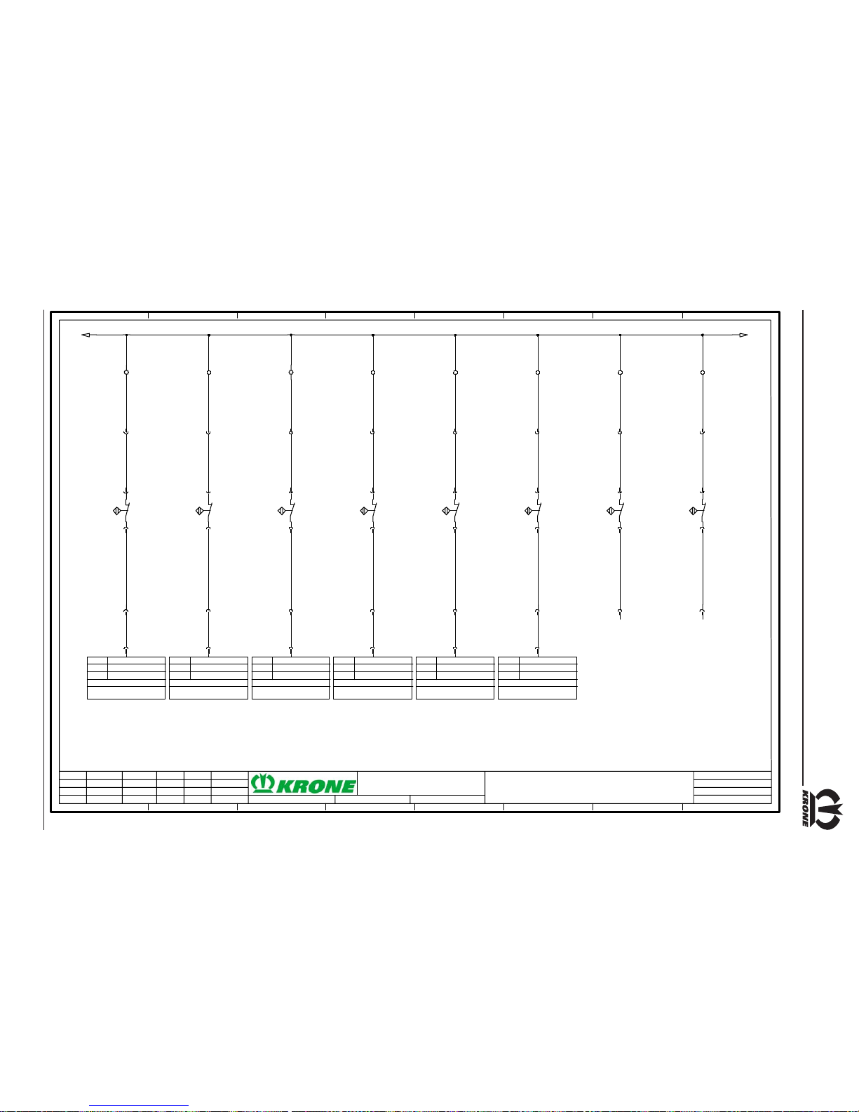
IV - 41
Medium / Comfort control unit
GND_NAM
/4.8
16.3
-X 100
3
-1X2a
3
+KB1X2-1X2b
1
+KB1X2-XB9a
1
2
+KB1X2-B9
eedl e connec ting r od
2
+KB1X2-XB9a
4
+KB1X2-1X2b
4
-1X2a
35
-JR1X 1b
Anschl.
I / O
Modul
X1_35
-A1
/2.4
DIG_14
Needle connecting rod
KMC 1
16.4
-X100
11
-1X 1a
11
+KB1 X1-1X1 b
1
+K B1X1- XB10 a
1
2
+KB1X1-B10
Knot ter moni tori ng
2
+K B1X1- XB10 a
12
+KB1 X1-1X1 b
12
-1X 1a
10
-J R1X 1b
Anschl.
I / O
Modul
X1_10
-A1
/2.4
DIG_11
Knotter monito ring
KMC 1
17.1
-X 100
5
-1X2a
5
+KB1X2-1X2b
1
+KB 1X2- XB11 a
1
2
+KB1 X2-B 11
Bale chute
2
+KB 1X2- XB11 a
6
+KB1X2-1X2b
6
-1X2a
20
-JR1X 2b
Anschl.
I / O
Modul
X2_20
-A1
/2.4
DIG _ 5
Bale chute
KMC 1
17.2
-X100
7
-1X 2a
7
+KB1 X2-1X2 b
1
+K B1X2 -XB1 2a
1
2
+KB1X2-B12
Bale set-down
2
+K B1X2 -XB1 2a
8
+KB1 X2-1X2 b
8
-1X 2a
22
-J R1X 2b
Anschl.
I / O
Modul
X2_22
-A1
/2.4
DIG_6
Bale se t-down
KMC 1
17.3
-X100
9
-1X2a
9
+KB1X2-1X2b
1
+KB1X2-XB13a
1
2
+KB1 X2-B 13
Front bale ejector
2
+KB1X2-XB13a
10
+KB1X2-1X2b
10
-1X2a
17
-JR1X 2b
Anschl.
I / O
Modul
X2_17
-A1
/2.4
DIG _ 2
Front bale e jector
KMC 1
17.4
-X100
11
-1X 2a
11
+KB 1X2- 1X2b
1
+KB1 X2-X B14a
1
2
+KB1X2-B14
Rear bale ejector
2
+KB1 X2-X B14a
12
+KB 1X2- 1X2b
12
-1X 2a
32
-JR1X2b
Anschl.
I / O
Modul
X2_32
-A1
/2.4
DIG_8
Rear bale ejector
KMC 1
18.1
-X 100
13
-1X2a
13
+KB1X2-1X2b
1
+KB 1X2- XB15a
1
2
+KB1 X2- B15
St ar wh eel 1
2
+KB 1X2- XB15a
14
+KB1X2-1X2b
14
-1X2a
18.2
-X100
15
-1X 2a
15
+KB1 X2-1X2 b
1
+K B1X2- XB16 a
1
2
+KB1X2-B 16
Star wheel II
2
+K B1X2- XB16 a
16
+KB1 X2-1X2 b
16
-1X 2a
GND_NAM
Sensor star wheel 1 + 2 (fo r t est only)
21.05.2003
1 2 3 4 5 6 7 8
Kloepper
12.03.2002G armann
1 2 3 4 5 6 7 8
BIG PACK 890/1270/1290 Comfort
5/1 0
Inputs
5
303 289-0
Krone-No.:
Person i. C. Location
NameDate
Dat e Plant
Repl. for Repl. byNorm
Sheet No.
Sh. of No.OriginState Modification
Insp.

IV - 42
Medium / Comfort control unit
+12 VSEN
/2.4
GND_SEN
/3.8
9.2
-X1 00
13
-1X1a
13
+KB1 X1-1X1 b
1
P
U
1+ 2-
3A
+KB1 X1-B 17
Bale channel flap pressure
11.2
14
14
2
+K B1X1- XB17 b
3
+KB 1X1- XB17b
15
+KB1X1-1X1b
15
-1X1a
3
-JR1X 2b
Anschl.
I / O
Modul
X2_03
-A1
/2.4
MULTI_1
Bale channel flap pressure
KMC 1
19
+K B1X1 -1X1 b
19
-1X1a
8.4
-X1 00
GND
/3.8
18
18
7.4
+12VEFU
/3.8
16
+KB1 X1-1X1 b
16
-1X1a
7
-JR 1X 2b
Anschl.
I / O
Modul
X2_07
-A1
/2. 4
MUL TI _3
Force of pressure right
KMC 1
17
+K B1X1 -1X1 b
17
-1X1a
23
-JR 1X 2b
Anschl.
I / O
Modu l
X2_23
-A1
/2.4
MUL TI _4
Force of pressure left
KMC 1
26
+K B1X1 -1X1 b
26
-1X1a
16
-JR1X2b
Anschl.
I / O
Modu l
X2_16
-A1
/2.4
LA_1
Force sensors simulation
KMC 1
1
+K B1X1 -XN1b
2 3 4 5
F
R
1
2
3
4
+Zugglied-B19
Right force sensor
1
-XB 19a
F
T315mA
1
ON DIP
23 4
1
ON DIP
234
Poti
Poti
Schalter
+12V0VSign re
Sign li
+12V0V-Sign
+Sign
rechts links
+12V0V-Sig n
+Sign
1234
1234 1234
+Zugglie
d
2 3 4
F
R
1
2
3
4
+Zugglied-B18
Left force se nsor
1
-XB18a
2 3
+12VSEN
/7.1
GND_SEN
/7.1
4
white
brown
black
grey
black
blue
blue
blue
white
brown
white
brown
black
21.05.2003
1 2 3 4 5 6 7 8
Kloepper
07.03.2002Garmann
1 2 3 4 5 6 7 8
BIG PACK 890/1270/1290 Comfort
6/1 0
Force meas urement
6
303 289-0
Krone-No.:
Person i. C. Location
NameDate
Dat e Plant
Repl. for Repl. byNorm
Sheet No.
Sh. of No.OriginState Modification
Insp.

IV - 43
Medium / Comfort control unit
+12 VSEN
/6.8
GND_SEN
/6.8
11.3
-X100
5
-1X 3a
5
+KB1 X3-1X3 b
1
+KB 1X3- XS1b
13
2
+K B1X3 -S1
Blade bar up
green
2
+KB 1X3- XS1b
6
+KB1 X3-1X3 b
6
-1X 3a
3
-J R1X 1b
Anschl.
I / O
Modul
X1_03
-A1
/2.4
MULTI_5
Blade bar up
KMC 1
9.3
7
7
3
11.4
-X100
8
-1X3a
8
+KB1X3-1X3b
1
+KB1X3-XS2b
13
2
+KB1X3-S2
Bl ade b ar d own
gree n
2
+KB1X3-XS2b
9
+KB1X3-1X3b
9
-1X3a
6
-JR1X 1b
Anschl.
I / O
Mo dul
X1_06
-A1
/2.4
MULTI_6
Blade bar down
KMC 1
9.4
10
10
3
12.1
-X100
17
-1X2a
17
+KB1X2-1X2b
1
+KB1X2-XS3b
13
2
+KB1 X2-S 3
Bale ejector in
green
2
+KB1X2-XS3b
18
+KB1X2-1X2b
18
-1X2a
27
-JR1X 1b
Anschl.
I / O
Modul
X1_27
-A1
/2.4
MULTI_8
Bale ejector in
KMC 1
10.1
19
19
3
12.2
-X100
20
-1X2a
20
+KB1X2-1X2b
1
+K B1X2- XS4b
13
2
+KB1X2-S4
Bale ejector out
gre en
2
+K B1X2- XS4b
21
+KB1X2-1X2b
21
-1X2a
21
-JR1X 1b
Anschl.
I / O
Modul
X1_21
-A1
/2.4
MULT I_7
Bale ejector out
KMC 1
10.2
22
22
3
12.3
-X 100
23
-1X2a
23
+KB1X2-1X2b
1
+KB1X2-XS5b
13
2
+KB1X2-S5
Bal e chut e up
yellow
2
+KB1X2-XS5b
24
+KB1X2-1X2b
24
-1X2a
39
-JR1X 1b
Anschl.
I / O
Modul
X1_39
-A1
/2.4
MULTI_9
Bale chute up
KMC 1
10.3
25
25
3
12.4
-X1 00
26
-1X2a
26
+K B1X2 -1X2 b
1
+KB1 X2-X S6b
13
2
+KB1X2-S6
Bal e chute do wn
yellow
2
+KB1 X2-X S6b
27
+K B1X2 -1X2 b
27
-1X2a
40
-JR 1X 1b
Anschl.
I / O
Modu l
X1_40
-A1
/2.4
MULTI_10
Bale chute down
KMC 1
10.4
28
28
3
+12VSEN
GND_S EN
21.05.2003
1 2 3 4 5 6 7 8
Kloepper
12.03.2002G ar mann
1 2 3 4 5 6 7 8
BIG PACK 890/1270/1290 Comfort
7/1 0
Manual control
7
303 289-0
Krone-No.:
Person i. C. Location
NameDate
Dat e Plant
Repl. for Repl. byNorm
Sheet No.
Sh. of No.OriginState Modification
Insp.

IV - 44
Medium / Comfort control unit
0V
/2.3
Anschl.
I / O
Modul
X2_01
-A1
/2.4
HBPWM_1
Control valv e
KMC 1
1
-JR1X 2b
29
-1X2a
29
+KB1X2-1X2b
1
+KB1 X2-X Y11b
1
2
-Y11
Control valve
2
+KB1 X2-X Y11b
Anschl.
I / O
Modul
X2_04
-A1
/2.4
HBPWM_2
Control valve
KMC 1
4
-J R1X 2b
30
-1X 2a
30
+KB1 X2-1X2 b
Anschl.
I / O
Modul
X1_30
-A1
/2.4
PWM_LA_8
Seat valve
KMC 1
30
-JR1X 1b
11
-1X3a
11
+KB1X3-1X3b
1
+K B1X3- XY10 b
1
2
-Y1 0
Seat valve
2
+K B1X3- XY10 b
12
+KB1X3-1X3b
12
-1X3a
3.3
-X100
Anschl.
I / O
Modul
X1_23
-A1
/2.4
PWM_LA_6
Main v alve (extend)
KMC 1
23
-JR1X 1b
13
-1X3a
13
+KB1X3-1X3b
1
+KB1 X3-X Y01b
1
2
-Y01
Main valve (extend)
2
+KB1 X3-X Y01b
14
+KB1X3-1X3b
14
-1X3a
3.4
-X1 00
Anschl.
I / O
Modul
X1_26
-A1
/2.4
PWM_LA_7
Main v alve (retract)
KMC 1
26
-J R1X 1b
15
-1X 3a
15
+KB1 X3- 1X3b
1
+KB1X3-XY02b
1
2
-Y0 2
Main valve (retract)
2
+KB1X3-XY02b
16
+KB1 X3- 1X3b
16
-1X 3a
4.1
-X100
0V
/9.1
21.05.2003
1 2 3 4 5 6 7 8
Kloepper
12.03.2002Garmann
1 2 3 4 5 6 7 8
BIG PACK 890/1270/1290 Comfort
8/1 0
Outputs
8
303 289-0
Krone-No.:
Person i. C. Location
NameDate
Dat e Plant
Repl. for Repl. byNorm
Sheet No.
Sh. of No.OriginState Modification
Insp.

IV - 45
Medium / Comfort control unit
0V
/8.8
Anschl.
I / O
Modul
X2_24
-A1
/2.4
PWM_LA_2
Blade bar
KMC 1
24
-JR1X 2b
17
-1X3a
17
+KB1X3-1X3b
1
+KB1 X3-X Y07b
1
2
-Y07
Bl ade b ar
2
+KB1 X3-X Y07b
18
+KB1X3-1X3b
18
-1X3a
4.2
-X 100
Anschl.
I / O
Modul
X2_30
-A1
/2.4
PWM_LA_3
Blade bar
KMC 1
30
-J R1X 2b
19
-1X 3a
19
+KB1 X3-1X3 b
1
+KB1X3-XY08b
1
2
-Y0 8
Blade bar
2
+KB1X3-XY08b
20
+KB1 X3-1X3 b
20
-1X 3a
4.3
-X100
Anschl.
I / O
Modul
X2_34
-A1
/2.4
HB PW M _ 5
Bale ejector
KMC 1
34
-JR1X 2b
21
-1X3a
21
+KB1X3-1X3b
1
+K B1X3 -XY05 b
1
2
-Y05
Bale ejector
2
+K B1X3 -XY05 b
22
+KB1X3-1X3b
22
-1X3a
4.4
-X 100
Anschl.
I / O
Modul
X2_14
-A1
/2.4
HBPWM_6
Bale ejector
KMC 1
14
-J R1X 2b
23
-1X 3a
23
+KB1 X3-1X3 b
1
+KB1X3-XY06b
1
2
-Y0 6
Bale e jector
2
+KB1X3-XY06b
24
+KB1 X3-1X3 b
24
-1X 3a
5.2
-X100
Anschl.
I / O
Modul
X2_26
-A1
/2.4
PWM_LA_4
Bale chute
KMC 1
26
-JR1X 2b
25
-1X3a
25
+KB1X3-1X3b
1
+K B1X3 -XY03 b
1
2
-Y03
Bale chut e
2
+K B1X3 -XY03 b
26
+KB1X3-1X3b
26
-1X3a
5.3
-X100
Anschl.
I / O
Modul
X1_22
-A1
/2.4
PWM_LA_5
Bal e chut e
KMC 1
22
-JR1X1b
27
-1X 3a
27
+KB 1X3- 1X3b
1
+KB1X3-XY04b
1
2
-Y0 4
Bale chute
2
+KB1X3-XY04b
28
+KB 1X3- 1X3b
28
-1X 3a
5.4
-X100
Anschl.
I / O
Modul
X2_35
-A1
/2.4
PW M _ LA _1
Release bale channel flap
KMC 1
35
-JR1X 2b
29
-1X3a
29
+KB1X3-1X3b
1
+KB1 X3-X Y09b
1
2
-Y09
Release bale channel flap
2
+KB1 X3-X Y09b
30
+KB1X3-1X3b
30
-1X3a
6.1
-X 100
0V
/10.1
21.05.2003
1 2 3 4 5 6 7 8
Kloepper
08.03.2002Garmann
1 2 3 4 5 6 7 8
BIG PACK 890/1270/1290 Comfort
9/1 0
Outputs
9
303 289-0
Krone-No.:
Person i. C. Location
NameDate
Dat e Plant
Repl. for Repl. byNorm
Sheet No.
Sh. of No.OriginState Modification
Insp.

IV - 46
Medium / Comfort control unit
0V
/9.7
Anschl.
I / O
Modu l
X1_24
-A1
/2. 4
HBPW M_7
Ma chin e ligh ting
KMC 1
24
-JR 1X 1b
20
-1X1a
20
+KB1 X1-1X1 b
1
+KB1X1-XH1
1
2
-H1
Ma chine li ghti ng
2
+KB1X1-XH1
21
+KB1 X1-1X1 b
21
-1X1a
6.2
-X1 00
Anschl.
I / O
Modu l
X2_06
-A1
/2.4
HB PW M _3
Electr. kn ot triggering
KMC 1
6
-JR 1X 2b
22
-1X1a
22
+K B1X1 -1X1 b
1
+KB1X1-XKnoter
2
+KB1X1-XKnoter
23
+K B1X1 -1X1 b
23
-1X1a
6.3
-X1 00
Anschl.
I / O
Modul
X2_27
-A1
/2.4
LA_2
Knotter cleani ng
KMC 1
27
-JR1X 2b
24
-1X1a
24
+KB1X1-1X1b
1
+KB1X1-X20b
1
+KB1X1-X20a
1
+KB1X1-XY30
1
2
-Y30
Knotter cleaning
2
+KB1X1-XY30
2
+KB1X1-X20a
2
+KB1X1-X20b
25
+KB1X1-1X1b
25
-1X1a
6.4
-X1 00
3
3
0V
Anschl.
I / O
Modul
X2_08
-A1
/2.4
HBPWM_4
Knotter cleani ng 2
KMC 1
8
-JR1X 2b
27
-1X1a
27
+KB1X1-1X1b
Reserve knotter tr iggering
21.05.2003
1 2 3 4 5 6 7 8
Kloepper
13.03.2002Garmann
1 2 3 4 5 6 7 8
BIG PACK 890/1270/1290 Comfort
10/ 1 0
Outputs for lighting / knotter blower
10
303 289-0
Krone-No.:
Person i. C. Location
NameDate
Dat e Plant
Repl. for Repl. byNorm
Sheet No.
Sh. of No.OriginState Modification
Insp.
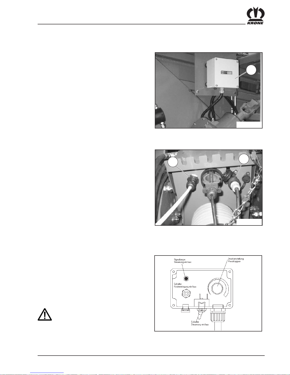
V - 1
Basic control unit
5. Control unit - Basic
5.1 General description
The electronics system consists of the distributor (1),
which contains the actual electronics, and the control
unit, which is used to operate the baler.
Distributor:
Position: on the left front of the machine under the front
cover.
Function: Electrical control of the machine
5.3 Operation
Switching on:
Turn on the electronics with the switch on the front side
of the control unit. After the electronics have been turned
on, the signal light comes on.
The knotter cleaning system can be turned on with the
switch on the left side of the control unit.
The turn dial on the right side of the control unit is used
to adjust the bale channel flap pressure.
The pressure is set to a fixed level. There
is no monitoring of any overload on the
machine.
Especially if the materials being
processed are moist or hard to compress,
the pressure must not be set too high. If it
is, the machine could be damaged.
5.2 Attaching
Electrical power supply: Connect the power supply
cable (12 V) to the 3-prong
power outlet (DIN 9680).
Control panel: The cable, which is
permanently connected to the
control unit, should be
connected to the socket on
the front metal cover.
BP890_0030
BPXC0050
1
BPXC0038
a
b

V - 2
Basic control unit
5.4 Description of the baling
process
At the beginning of the baling process, the pressure
must be set initially to about 50 bar. The pressure can be
read on the pressure gauge. When the pressure has
reached 50 bar, the baling process can begin. Once the
channel has been filled and the bale channel flaps have
been opened, the pressure can be set high enough so
that the bales are sufficiently solid.
Because there is no monitoring of a
possible overload on the machine, the
pressure must be adjusted very carefully
to ensure that the machine is not
permanently damaged.

V - 3
Basic control unit
5.5 Circuit diagram of the basic control unit
3
+KB1X1-X20b3+KB1X1-X20a
1
+KB1X1-XY1b2
-Y1
Pressure cont rol valve
2
+KB1X1-XY1b2
1
1
1
+KB1X1-XY2b
-Y2
Knotter blower valve
2
+KB1X1-XY2b
2
+KB1X1-X20a2+KB1X1-X20b
SW_ON
/1.90V/1.9
DruckSignal
/1.9
+2,5V
/1.9
SW_KnotReinigung
/1.9
0V (Steuerung)
/1.9
0V
1.1
-X100
2.1
-X100
1.4
-X100
Poti
Poti
(+12V)
(0V)
Poti
Poti
Poti
min
max
1234567
-N1
Current controller
15
18
-K3
7
1.2
-X100
+B1+A1
+A2
-K3
eltako time relay DZ12TI-001-12..230V UC
1.3
-X100
6
Distributor
21.05.2003
0 1 2 3 4 5 6 7 8 9
Schrameyer
01.07.2002Garmann
0 1 2 3 4 5 6 7 8 9
BIG PACK 890/1270/1290 BASIC
2/2
Distributor
2
303 287-1
Krone-No.:
Person i. C. Location
NameDate
Date Plant
Repl. for Repl. byNorm
Sheet No.
Sh. of No.OriginState Modification
Insp.

V - 4
Basic control unit
1
2
-H1
On/Off
0
1
1
2
-S1
Knotter cleaning on/off
0
1
1
2
-S2
Electronics on/off
1
2
3
-R1
10k, Pressure setting
-F1
20A
-F2
10A
+KB1X4-1X2b
31
15/30
31
+KB1X3-1X2a
1234567
+KB1X 2-XDisa
15/30
+KB1X3-1X1a
31
1234567
+KB1X 1-XDisb
15/30
31
+KB1X1-1X1b
+2,5V
/2.3
DruckSign al
/2.3
0V
SW_KnotReinigung
/2.3
SW_ON
/2.3
0V (Steuerun g)
/2.3
0V
/2.3
blue
pink
grey
yellow
green
brown
white
12V plug (control)
Terminal plug
Tractor
Krone basic operation
Battery +12V
Drawbar
Battery 0V
21.05.2003
0 1 2 3 4 5 6 7 8 9
Garmann
06.11.2002Garmann
0 1 2 3 4 5 6 7 8 9
BIG PACK 890/1270/1290 BASIC
1/2
Power supply/operation
1
303 287-1
Krone-No.:
Person i. C. Location
NameDat e
Date Plant
Repl. for R epl. byNorm
Sheet No.
Sh. of No.OriginState Modi fication
Insp.

VI - 1
Working with the Big Pack Baler
6 Working with the Big Pack Baler
6.1 Special safety instructions
• The following is a basic rule for all maintenance, mounting, repair and adjustment tasks:
Turn off the PTO. Turn off the engine and remove the ignition key. Apply the flywheel brake.
• During operation, maintain an adequate safety distances from all movable parts of the Big
Pack Baler. This applies especially to the collecting mechanism (pick-up) of the crop.
• Put the Big Pack baler into operation only if all protective devices are attached and in
proper working order!
• Eliminate blockages only when the machine is stopped. Turn off the engine and remove the
ignition key. Apply the flywheel brake.
• If dangerous situations arise, turn off the PTO immediately and bring the Big Pack Baler to a
stop.
• Never allow the Big Pack Baler to run without operating personnel on the tractor.
6.2 Basic setting on the Big Pack Baler
6.2.1 Pick-up
Lift the pick-up for driving in the turn space or when driving backward!
Adjusting the working height
To adjust the height of the pick-up, raise it and secure it against being unintentionally
lowered by moving the shut-off valve on the right side of the machine.
The working height can be adjusted on the feeler wheels
(3) on either side of the pick-up. The working height can
be adjusted on the feeler wheels (3) on either side of the
pick-up. Pull the spring cotter pin (2) and move the feeler
wheels into the desired position on the perforated bar (1).
Secure the feeler wheels in place with the spring cotter
pin.
Make certain while doing so that the
feeler wheels on either side of the pickup are in the same position on the
perforated bar.
2
3
BP800015
1
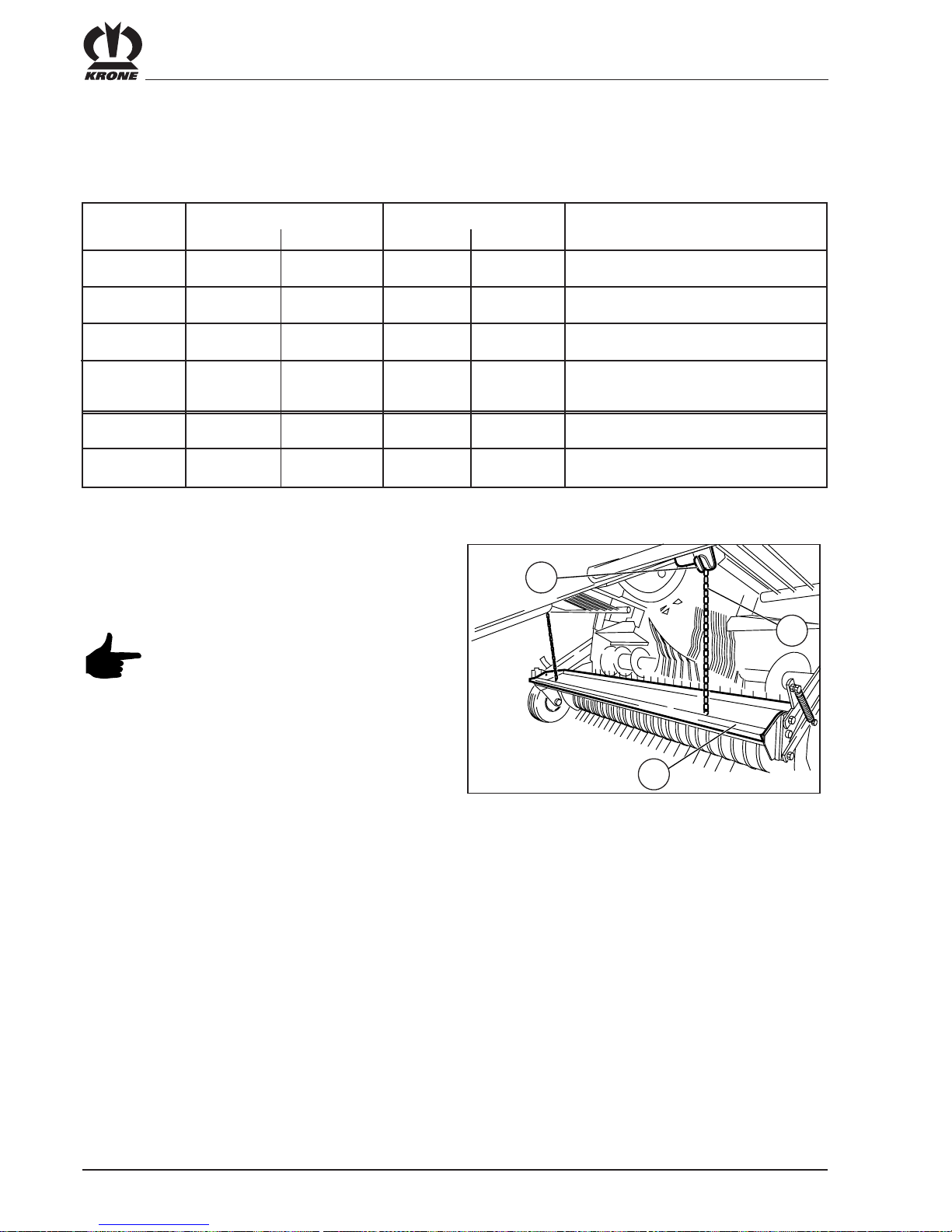
VI - 2
Working with the Big Pack Baler
Height adjustment of the baffle plate (roller-type crop guard)
The height adjustment of the baffle plate depends on the following factors:
Crop Length of the crop Windrow size Which setting?
Long Short Large Small
Straw / Hay X X Baffle plate high
Straw / Hay X X Baffle plate low
Straw / Hay X X Baffle plate high
Straw / Hay X X Baffle plate low
Silage X Baffle plate high
Silage X Baffle plate low
The height adjustment of the baffle plate (3) can be
made on the retaining chains (2) that are suspended on
the bracket (1) on either side of the machine.
Make certain that the chains on the
suspensions are of the same length.
BP380-7-037
2
1
3

VI - 3
Working with the Big Pack Baler
6.2.1.1 Special safety instructions
The following is a basic rule for all maintenance, mounting, repair and adjustment tasks:
• Bring the Big Pack Baler to a stop.
• Turn off the engine and remove the ignition key.
• Secure the tractor and Big Pack baler against rolling.
• Secure the pick-up against being lowered unintentionally.
• There is great danger of injury while the blades are being mounted and dismounted. The
blades should only be touched with suitable gloves.
• Apply the flywheel brake.
6.2.1.2 General
The Big Pack XC has a cutting system with a cutting
cylinder and fixed blades.
Cutting allows for improved further processing of the big
pack and makes it possible to increase the density of baled
material. The blades can be swivelled out of the conveyor
channel hydraulically from the tractor if there are blockages.
Each blade is separately protected against overload.
The machine can also be used without blades. The cutting
cylinder than takes on the function of a conveyor between
the pick-up and the pre-baling channel.
The cutting system of the Big Pack 890 XC can be fitted
with a maximum of 16 blades. The Big Pack
1270 XC / 1290 XC with a maximum of 26 blades. The
theoretical cutting length is then 44 mm.
The cutting length is determined by the number of blades
used:
• Big Pack with XC cutting system
To activate the cutting mechanism, the blade control
(Position 1) is turned on and the cutting system is
moved up as far as it will go hydraulically.
6.2.1.3 Cutting length
BP800055
1
0
6.2.1 Cutting system XC
Cutting
length
mm
Number of blades B lade
compartment
used
Setting
BP 890 BP 1270
BP 1290
-00 any0
44 16 26 each 1
88 8 13 every 2nd 1
132 4 6 every 3rd 1
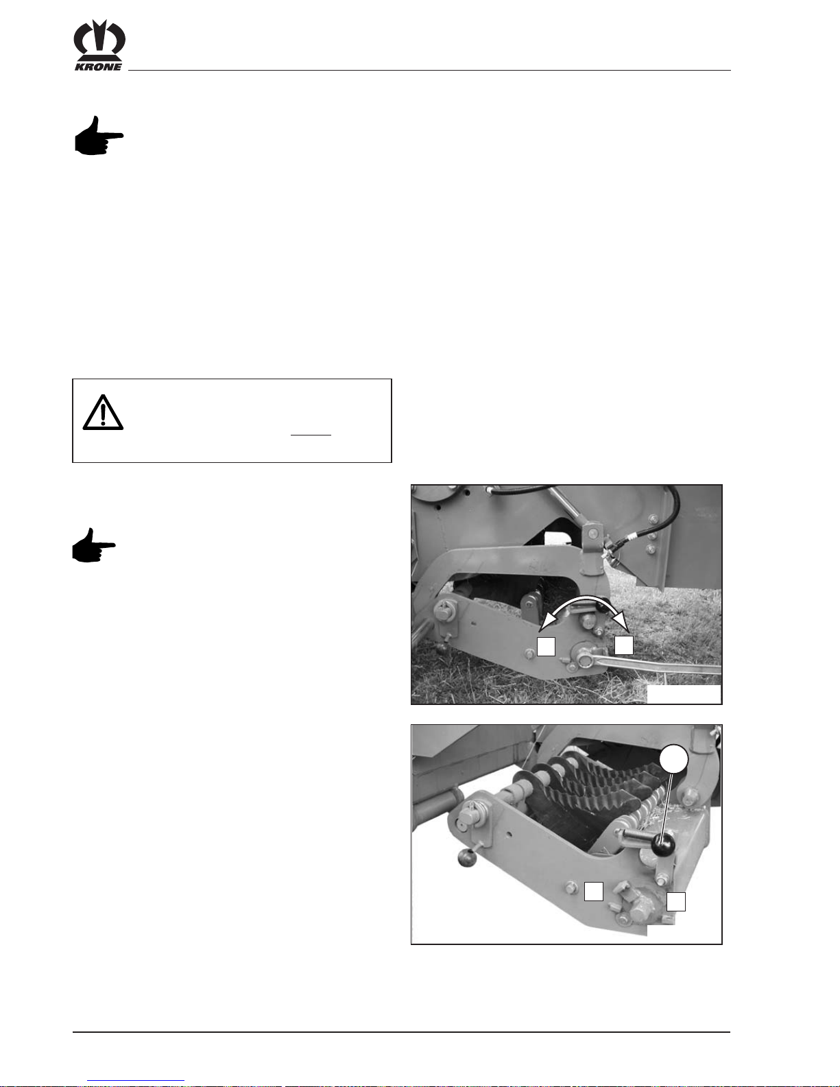
VI - 4
Working with the Big Pack Baler
6.2.1.4 Changing blades
The conveyor channel must be cleaned
before blades are changed.
Blades are changed on the right and left side of the
machine.
The left side of the machine is described below. The
same applies for the right side of the machine.
Lower the cutting system.
• Lower the cutting system with the tractor hydraulics
(with the Comfort electronics system: Switch the
tractor hydraulics to Raise and hold down the Lower
blade bar in the control display until the cutting
system has been lowered all the way.)
• Remove the ignition key and turn off the electrical
system on the control box
BP800056
1
0
Move the blade control from Position (1) to Position (0)
with a key (SW30).
When shifting positions, be careful that
the spring pressure takes effect on the
key (danger of injury!)
BP800057
1
0
1
Unlock the cutting system by activating the lever (1) and
remove it as far as the stopper.
The cutting system must not be started
up again until both halves of the cutting
system are retracted and locked on the
side.

VI - 5
Working with the Big Pack Baler
BP800058
II
I
1
2
Unlocking the blade shaft
• Unlock the locking lever (1) (Pos. II)
• The blades (2) can now be removed vertically upward
• Set the new blades in place.
• Secure the blade shaft with the locking lever (1)
(Pos. I)
• Push in the two halves of the cutting system (1) on
the side until the locking lever (2) snaps into place
by itself.
• Depending on how they will be used, the blades can
now be turned on with a key (SW 30) (Pos. I) or can
remain in the “0” position (Pos. II).
• Lift the cutting system hydraulically
BP800059
I
II
2
1
6.2.1.5 Zero setting of blades
Turning off the blades mechanically on the right
and left
Move the blade control on both sides to the 0 setting
with a key (SW 30).
When shifting positions, be careful that
the spring pressure takes effect on the
key (danger of injury!)
The zero position of the cutting system is
possible in the lowered or raised state.
Turning off the blades hydraulically
The cutting system can be lowered with a hydraulic
cylinder. Because there is not enough free area on the
ground, the cutting system must be raised immediately
again after the blockage has been eliminated.
The purpose of the hydraulic zero
position of the blades is to make it
possible to eliminate any blockages.
Position I = blade shaft locked
Position II = blade shaft unlocked
BP800059
I
II
2
1
Position I = blades activated
Position II = blade “0” position
The cutting system must not be started
up again until both halves of the cutting
system are retracted and locked on the
side.

VI - 6
Working with the Big Pack Baler
6.2.2Bale chute
When it is unfolded, the bale chute represents an
extension of the baling channel. To make it possible to
set down big packs properly, the bale chute must be on
the same level as the base of the baling channel.
This can be adjusted with the nuts (1) on either side of
the baling channel. This makes it possible to adjust the
length of the bale chute support chain (2).
BP380-7-038
2
1
6.2.2.1 Hydraulically collapsable bale
chute with rollers
A version of the machine with a hydraulically folding bale
chute having five rollers is available.
Secure the vehicle and machine
against rolling.
Make certain everyone leaves the
dangerous area when the bale chute
is being retracted or extended.
The machine must only be driven on
public highways with the bale chute
retracted.
BP800065
3
a
b
The way the bale chute works depends on the version
you have.
In the design for basic or medium operation, the control
device for the hydraulic line must be switched to Raise
on the tractor.
The operating control device (3) for the hydraulically
folding bale chute and the bale ejector is located at the
rear left next to the parking brake.

VI - 7
Working with the Big Pack Baler
• Open the shut-off valve (1).
• To extend the bale chute (2), raise the safety sleeve
(3) and move the lower control lever (4) into
position (b).
• To retract the bale chute (2), raise the safety sleeve
(3), activate the control lever (4) and move it to
position (a).
Position a = fold the bale chute up
Position b = fold the bale chute down
For travel on public highways, the roller
chute must always be folded up and the
shut-off valve must be closed.
2
a
b
BP800064
4
3
1
Operation with the Comfort version is described in
Section 4.4.3!
6.2.2.2 Emptying the baling channel
No one must be on the maintenance
platform unless the machine is stopped.
Turn off the engine and remove the
ignition key. Apply the flywheel brake.
Before the baling channel is emptied, any baling material
that is in the baling channel should be tied up. To do
this, trigger the tying process manually (see Section
6.4.6 „Triggering the tying process manually“).
Open the baling channel on the control panel. The
procedure is described in Section 4.7 „Loosening the
baling channel“ for the Comfort design and in Section
6.2.3 „Regulating the force of pressure“ for the Basic or
Medium design.
BP380-7-052
1
1
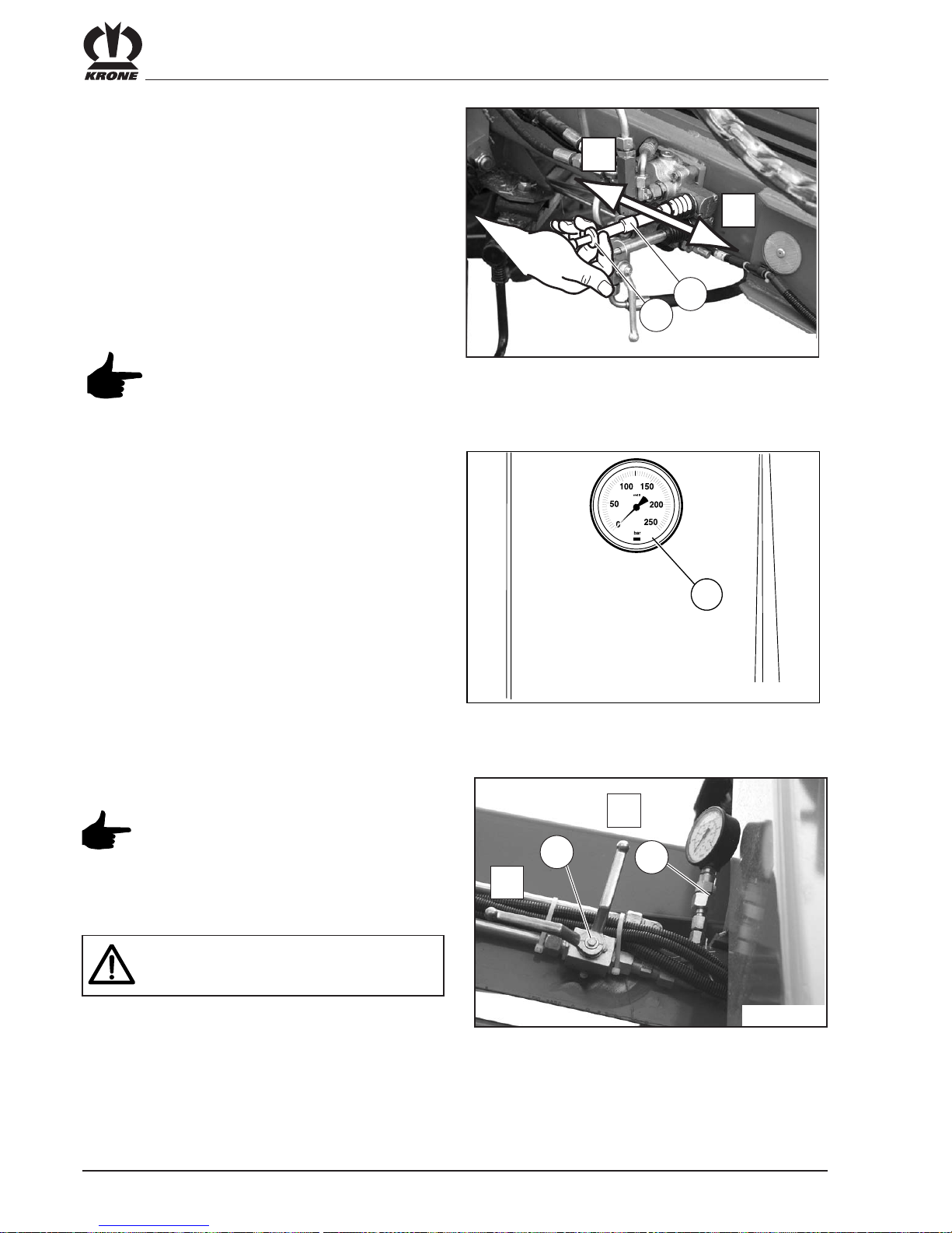
VI - 8
Working with the Big Pack Baler
6.2.3Regulating the force of pressure
The force of pressure in the baling channel is regulated
by an electronic/hydraulic system. The force of pressure
can be adjusted from the tractor controls. The pressure
at any given time in the baling hydraulic system can be
read on the pressure gauge (1) at the front right (see
Section 4 and 5).
An additional pressure gauge (1) is located on the left
side of the machine on the baling channel at the top in
front of the yoke
BP800017
1
a
b
2
BP-VFS-012
1
The shut-off valve (2) is used to release
the baling channel.
The machine is in the working position in
setting (a).
To release the baling channel, use
control setting (b) (tank return)
If the shut-off valve is in Position (b), it is
not possible to build up pressure.
In the Comfort design, this function can be switched
from the control panel (see Section 4.7 Opening / closing
the bale channel flaps)
For the Comfort design
For the Basic and Medium designs
After big baling is turned off, it is
absolutely essential to move the bale
ejector to the forward position.
In the Basic or Medium design, this is done by activating
it with the upper control lever on the rear left of the
machine.
• Raise the safety sleeve (2) and move the control
lever (3) to position (a) or (b).
Position (a): The remaining bale ejector moves back.
Position (b): The remaining bale ejector moves
forward.
BP800063
a
b
3
2
 Loading...