

Krone AM 203 CV, AM 243 CV, AM 283 CV + B, AM 243 CV + B, AM 283 CV Operating Instructions Manual
No. 227-4 GB
Operating Instructions
Disc Mower
AM 203 CV
AM 243 CV / + B
AM 283 CV / + B
(from machine no. 403 700)

We
declare under our sole responsibility, that the product
to which this declaration relates corresponds to the relevant basic safety and health
requirements of the Directive 89/392 (EEC) and to the requirements of the other rlevant
Directives:
Heinrich-Krone-Str. 10, D-48480 Spelle
Maschinenfabriken Bernard Krone GmbH
Spelle, 10.05.95
(Heinz Krone, Board of Directors)
(Dr. Josef Horstmann, Designing office sub-manager)
(Josef Jungehüser, Quality assessment manager)
EC Declaration of Conformity
according to Directive 89/392/EEC
Dear customer,
Here are the operating instructions for the KRONE product you
purchased.
These operating instructions contain important information for the
proper use and safe operation of the machine.
If these operating instructions have for any reason become
completely or partially redundant, you can obtain replacement
operating instructions for your machine with the specification
numbers listed overleaf.
Krone-Disc Mower
Models: AM 203 CV; AM 243 CV; AM 243 CV + B;
AM 283 CV; AM 283 CV + B
1
This symbol is designed to draw attention
to the safety instructions contained in the
operating instructions. These instructions
must be observed to prevent accidents.
I. Foreword
Dear customer,
We thank you for the trust you have placed in us by
purchasing this machine.
When you received this machine, the dealer should
have given you instructions for the operation,
maintenance and adjustment of the machine.
However, this brief introduction to the machine can
not replace a detailed acquaintance with the different
tasks and functions of the machine and the proper way
of treating it.
These operating instructions are designed so that you
are extensively informed of the activities required in
each area, from commissioning and operation to the
maintenance and care of the machine. The structure of
the individual chapters in the text and illustrations
corresponds to the sequence of work procedures when
you use the machine.
Read these operating instructions carefully before you
use the machine, and pay special attention to the
safety instructions.
Important: To avoid accidents and to ensure
maximum results, no alterations may
be made to the machine without the
manufacturer´s permission. Similarly,
the machine must only be used under
the conditions prescribed by Krone.
All information, illustrations and technical information in
the operating instructions represent the latest status at
the date of publication. The company reserves the right
to make constructional alterations at any time and
without prior notice or obligation.
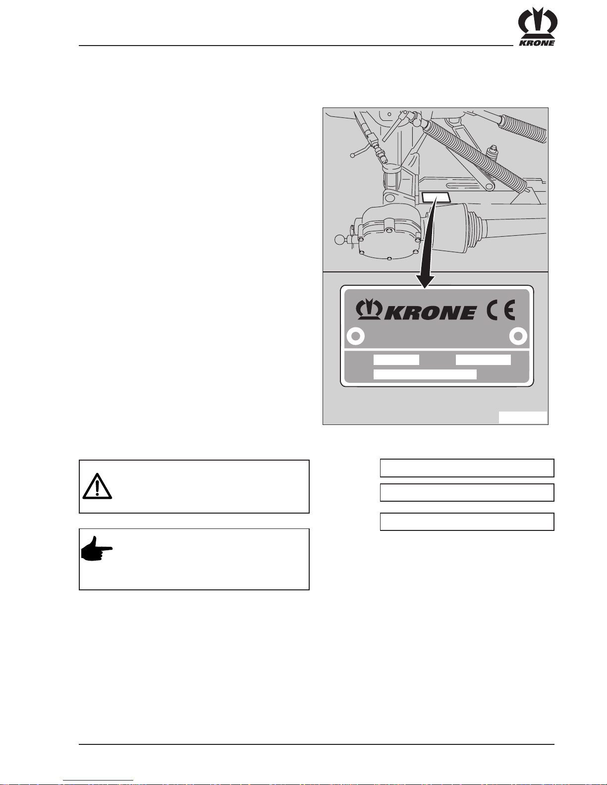
Mach. No.
Type
Year
When ordering replacement parts, the machine type,
machine number and year of manufacture must be
given. These details can be found on the identification
label on the machine.
We recommend that these details be entered in the
above boxes so that they are readily available.
And please remember that imitations and copies of
parts, especially wearing parts, do not keep what they
appear to promise. Material quality is difficult to test
visually, therefore special care is required when
purchasing cheap offers and imitation parts!
The simplest remedy:
Purchase only original KRONE parts!
Ordering Replacement Parts
You will find this symbol at various point in
the operating instructions. It gives special
handling instructions which should be
particularly observed in the use of the
machine
AM-1-006
Maschinenfabrik Bernard Krone GmbH
Heinrich-Krone-Straße 10, D 48480 Spelle
Jahr
Année
Masch. Nr
No. de série
Type
Made in
W.-Germany

2
List of Contents
I. Foreword ..............................................................................................................................1
II. List of Contents .....................................................................................................................2
III. General..................................................................................................................................3
1. Introduction
1.1 Position of Information Labels with safety-relevant contents on the Machine.......................6
1.2 Position of General Information Labels on the Machine .......................................................8
1.3 Technical Data for Disc Mower .............................................................................................9
2. Preparing for Operation
2.1 Attaching the Disc Mower to the Tractor.............................................................................10
2.2 P.T.O. Shaft.........................................................................................................................12
2.3 Jack Stand...........................................................................................................................13
2.4 Conditioner Drive (lever change gearbox) ..........................................................................13
2.5 The angle of the mower to the tractor .................................................................................14
2.6 Preparing to turn .................................................................................................................14
2.7 Transport Position ...............................................................................................................15
2.8 Detaching the Disc Mower to the Tractor............................................................................16
3. Adjusting the Disc Mower
3.1 Adjusting the Top Link Arm Coupling Point ........................................................................18
3.2 Adjusting the Safety Breakaway unit ..................................................................................18
3.3 Adjusting the Compensating Spring for the Cutter Beam ...................................................19
3.4 Adjusting piece for lifting cylinder and flotation spring ........................................................19
3.5 Basic Setting for the Tractor Lower Link Arm .....................................................................19
3.6 Adjusting the Swath Width ..................................................................................................20
3.7 Adjusting the cutting height .................................................................................................20
3.8 Changing Blades on the Cutting Discs with Blade Screw Connectors ...............................21
3.9 Adjusting the Conditioner Speed ........................................................................................22
3.10 Adjusting the Conditioner Cover Plate ................................................................................22
3.11 Adjusting the Position of the Condtioner rotor to the Cutterbar .......................................... 23
4. Maintenance
4.1 General................................................................................................................................25
4.2 Oil Level Check and Oil Change for Cutterbar....................................................................26
4.3 Oil Level Check and Oil Change for Main Gearbox ............................................................26
4.4 Oil Level Check and Oil Change for Gearbox, Mower Drive/Conditioner Drive .................27
4.5 Oil Level Check and Oil Change for the 1000 rpm power take off......................................27
4.6 Unlocking the Overload Coupling on the Drive Shaft to the Cutterbar
and on the Conditioner Drive (Walterscheid) ......................................................................28
4.7 Preparing the overload clutch for use (ByPy) .....................................................................28
4.8 Bleeding the overload clutch of the universal joint drive shaft
and of the double joint.........................................................................................................28
4.9 Lubrication...........................................................................................................................29
5. Conditioner and Protective Cloth Covers.......................................................................31
6. Wide swath hood...............................................................................................................32
7. Winter Storage ...................................................................................................................34
8. Start-up after Winter Storage ...........................................................................................34
Supplement to Operating Instructions
1. Assembly Instructions (initial installation) ........................................................................39
2. Mounting the Gearbox for a 1000 rpm Power Take-Off Shaft .........................................50

3
5. The operator´s clothing should be tight fitting. Avoid
wearing loose fitting clothes.
6. Keep the machine clean to prevent the danger of fire!
7. Before starting the machine and moving off, check the
danger area around the tractor (children!). Good visibility
is absolutely essential!
8. Carrying passengers on the implement during work or
transport is not permitted.
9. Make sure that the implement is correctly coupled, and
that it is only fixed and secured with the prescribed
fittings!
10.Make sure that the supporting devices, jacks etc. are
in the correct position during assembly and removal!
11.Special care is required when equipment is being
coupled to the tractor or detached from the tractor!
12.Ballast weights must always be attached in the
prescribed way at the designed attachment points!
13.Adhere to the permitted axle loads, total weights and
transport dimensions!
14.Check and fit transport equipment – e.g. lighting,
warning signs and, if required, protective equipment!
15.Operating equipment for remote controls (ropes, chains,
rods etc.) must be laid out in such a way that, whatever
the working or transport position, it can not inadvertently
cause any movements.
16.Prepare equipment for road transport as prescribed by
the manufacturer, and lock the equipment in accordance
with the manufacturer's regulations!
17.Never leave the driver´s position when the tractor is in
motion!
18.The speed of travel must always be suited to the
environmental conditions! Avoid any sudden turns
when travelling uphill, downhill or across a slope!
19.The handling, steering and braking of the tractor is
affected by integrated or attached equipment and
ballast weights. Make sure that you allow for more
flexibility in steering and braking!
20.When turning, remember to take account of the wide
load and/or the greater weight of the equipment!
21.Only switch on equipment when all protective
devices are fitted and in protection position!
2. Safety and Accident Prevention
Regulations
1. Take note of both the regulations in these operating
instructions and also the general safety and accident
prevention regulations!
2. The attached warning and information signs give
important advice for safe operation. Observing them
will enhance your safety!
3. When you use public roads, make sure you observe
the relevant traffic regulations!
4. Make sure you know all equipment and controls before
you begin working with the machine. When you are
operating the machine, it´s too late!
Basic rule:
Before any public roads are used and
before the machine is started, check the
disc mower and the tractor for roadworthiness and operational safety.
1. Operation in Accordance with
Specifications
The disc mower is designed solely for normal agricultural
use (operation in accordance with specifications).
Any use of the machine for other purposes is deemed to
be not in accordance with specifications. The manufacturer
bears no responsibility for any resulting damage; such use
is entirely at the operator´s risk.
Use in accordance with specifications also includes
adherence to the operating, maintenance and service
instructions prescribed by the manufacturer.
The disc mower must only be used, maintained and
repaired by personnel who are acquainted with the machine
and have been informed of the danger involved.
The applicable accident prevention regulations and all
other generally recognized safety, health and road traffic
regulations must be adhered to.
Any unauthorized alterations to the machine render any
liability for damage undertaken by the manufacturer null
and void.
III. General

4
,
22.Persons are not allowed to enter the working area!
23.Keep clear of the area of rotation and swing of the
equipment!
24.Hydraulic controls must only be operated if no persons
are in the swing area!
25.Power operated parts (e.g. by hydraulics) contain
danger points which can cause injury by bruising and
grazing!
26.Before leaving the tractor, rest the mower on the
ground, switch off the engine and remove the ignition
key!
27.Make sure that no personnel go between the tractor
and the implement unless the tractor is protected from
rolling by the parking brake and/or wheel blocks!
3. Attached Equipment
1. Special care is required when the implements is
being connected to the tractor or disconnected from
it!
2. The implement must only be coupled to the
appropriate fittings (e.g. the 3-point connection), and
they must be so secured (transport, operation) that
unintentional lifting or lowering of the implement is
not possible.
3. In three-point connection, it is absolutely essential
that the hitching categories of the tractor and
attachment (e.g. power take-off shaft speed,
hydraulics) are matched!
4. When operating the external controls for three-point
connection, make sure that nobody goes between
the tractor and the implement (danger of injury)!
4. Power Take-Off shaft Operation
1. Only the P.T.O. shafts prescribed by the manufacturer
may be used!
2. Both male and female guard tubes and cones of all
P.T.O. shafts must be fitted and in good condition!
3. Observe the tube overlap prescribed for P.T.O. shafts
in transport and operating position!
4. Before installing or removing the P.T.O. shafts, make
sure to turn off the power take-off shaft and the engine,
and remove the ignition key!
5.When using P.T.O. shafts with overload or free wheel
clutches that are not covered by the guards on the
tractor, the overload or free wheel clutches must be
fixed on the implement side!
6. Always ensure correct assembly and guarding of the
P.T.O. shaft!
7. Protect the P.T.O. shaft guard from rotating with the
shaft by fitting the chains!
8. Before switching on the power take-off shaft, make
sure that the p.t.o. speed of the tractor matches the
permitted speed of the implement!
9. Before switching on the power take-off shaft, make
sure that nobody is in the danger area of the implement!
10.Never switch on the power take off shaft when the
tractor engine is turned off!
11.Any work on the power take-off shaft may only be
carried out when nobody is in the area of the rotating
power take-off shaft or P.T.O. shaft.
12.The power take-off shaft should always be turned off
when the angle is too great or the p.t.o. shaft is not
required!
13.Danger! Working elements continue to rotate after the
power take-off shaft is turned off! Do not approach the
machine during this time! Work may only be carried out
on the machine when the machine is fully stationary
and the rotating parts have been secured by the
parking brake.
14.Cleaning, lubrication or adjustment of the P.T.O. shaft
or any equipment driven by the power take-off shaft
may only be carried out when the p.t.o. shaft and the
engine are turned off and the ignition key has been
removed! Rotating parts must be secured with the
parking brake.
15.Place the detached P.T.O. shaft on the support bracket
provided!
16.After removing the P.T.O. shaft, place the protective
cover on the stub of the power take-off shaft!
17.Any damage must be repaired immediately before any
work is carried out with the attachment!

5
4. When there are functional hydraulic connections
between the machine and the implement, all
coupling sleeves and plugs must be marked to
prevent operating errors. If the connections are
switched, the functions are reversed (e.g. lifting
and lowering) – this can cause accidents!
5. Hydraulic hoses must be checked regularly, and
they must be replaced if they are damaged or
worn. Replacement hoses must conform to the
technical requirements of the implement
manufacturer!
6. When tracing leaks, suitable aids should be used
to prevent injury!
7. Fluid leaking under high pressure (hydraulic oil)
can penetrate the skin and cause serious injury!
When injury occurs, consult a doctor immediately!
Danger of infection!
8. Before carrying out any work on the hydraulic
systems, lower the machine to the ground,
depressurize the system and turn off the engine!
5. Hydraulic System
1. The hydraulic system is pressurized!
2. When connecting hydraulic cylinders and motors,
make sure that the hydraulic hoses are correctly
coupled!
3. When connecting hydraulic hoses to the tractor´s
hydraulic system, make sure that all pressure has
been released from the hydraulics of both the
tractor and the implement!
6. Maintenance
1. Repair, maintenance and cleaning work and the
correction of malfunctions must always be carried out
only when the drive is turned off and the engine is at
a standstill! Remove the ignition key! Apply the parking
brake.
2. Nuts and bolts must be checked regularly for tightness,
and tightened if necessary!
3. When carrying out maintenance work on the machine
in a lifted position, it must always be supported on
suitable jacks.
4. When replacing fittings that contain cutting blades,
always use suitable tools and gloves!
5. Oil, grease and filters must be correctly disposed
of!
6. The power supply must always be disconnected
before any work is carried out on the electrical system!
7. If protective devices are subject to wear, they must be
checked regularly and replaced in good time!
8. When electric welding is carried out on the tractor and
any fitted attachments, the cables must be disconnected from the generator and battery!
9. Replacement parts must conform at least to the
technical requirements defined by the manufacturer!
The best guarantee is to use only original KRONE
parts!
10.Where gases are stored, only refill with nitrogen.
Danger of explosion!

6
1. Introduction
1.1 Position of the warning signs, with safety-technical information, on the machine
The KRONE Disc mower is equipped with all necessary safety features (protective equipment). Not all danger
points on this machine can be completely safeguarded with regard to the function of the machine. On the machine
you will find appropriate warnings that point out this residual danger.
We have designed these danger notices in the form of so-called warnings symbols. For the position of these
warning notices and their meaning/explanation, please refer to the following information.
Make sure that you are fully conversant with the meaning of the warning symbols. The text
next to the symbols and the position on the machine where the notices are displayed provide
information about the specific danger points on the machine.
4
2
6
5
6
3
2
1

7
939 572-0
Order No. 939 572-0 (1x)
Move guards into
position.
4
5
6
Do not touch any moving
parts of the machine.
Wait until they are
completely stationary.
Order No. 939 410-2 (1x)
Keep at a safe
distance when the
engine is running.
Order No. 942 197-1 (2x)
3
2
Never put your hand into
the danger area as long as
parts may be moving.
Order No. 942 196-1 (3x)
Read and take note of
the operating
instructions.
Order No. 939 471-1 (1x)
1
The PTO shaft speed must not exceed 540 rpm!
The operating pressure in the hydraulics system
must not exceed 200 bar.
Order No. 939 100-4 (1x)

8
1.2 Positions of the general information labels on the machine
939 428-1 (1x)
3
939 180-2 (1x)
2
939 567-1 (1x)
1
939 515-1 (1x) AM 203 CV
939 518-2 (1x) AM 243 CV
939 519-2 (1x) AM 283 CV
4
942 132-0 (1x)
6
939 511-1 (1x) AM 203 CV
939 512-2 (1x) AM 243 CV
939 513-2 (1x) AM 283 CV
5
8
8
61 274 5
939 531-1 (1x)
7
180
939 531-1
8
139 888-0
139 889-0
112
939 567-1
139-888
139-889
QS
Kontrolle frei
Datum
Unterschrift:
939 428-2
939 548-0 (1x)
with screw
connection blades
942 009-2 (1x)
with quickrelease blades

9
Type
Cutting width [mm] 2000 2400 2800
Transport width Tractor width Tractor width Tractor width
Number of mowing discs 3 4 5
Number of mowing cylinders 2 2 2
Conditioning system V-shaped flail. V-shaped flail. V-shaped flail.
Speed of conditioner rotor [rpm] 600 & 900 600 & 900 600 & 900
Width of conditioning system [mm] 1600 2000 2400
Swath width [m] 0.8 - 1.6 0.9 - 2.0 1.2 - 2.4
(0,9 - 2,3) (1.2 - 2.7)
Area covered [hectares/hour] 2.5 3 3.5
Power consumption [kW/PS] 33/45 37/50 44/60
Power take-off shaft speed [rpm] 540 540 540
Weight of machine [kg] 760 810 860
Required hydraulic connections 1 x Single acting 1 x Single acting 1 xSingle acting
Required Quantities and Lubricant Designations for Gearboxes
SAE 90
For biological lubricants, the oil change intervals must be strictly adhered to due to ageing of
the oils.
AM 203 CV
AM 243 CV
(AM 243 + B)
1.3 Technical Data for Disc Mower AM 203 CV / AM 243 CV / AM 283 CV
Biological lubricants
Required quantity [litres] Oil type Brand name
Main gearbox 0,3 SAE 90
Gearbox of
conditioner drive
Auxiliary gearbox
for 1000 rpm pto
on request
Mowing beam
AM 203 CV 4
AM 243 CV (+B) 5
AM 283 CV (+B) 6
1,5
SAE 90
0,2
SAE 90
AM 283 CV
(AM 283 CV + B)

10
2. Preparing for Operation
2.1 Attaching the Disc Mower to the Tractor
5. The protective cloth covers must be regularly
checked. Covers that are worn or damaged must
be replaced.
6. The protective features on the mower, e.g. cloth
covers and guard plates, are designed as
protection from stones etc. that are thrown out,
and also to prevent access to dangerous parts of
the machine. Therefore it is essential that they
are placed in position before work commences.
7. When the mower is being lowered from transport
position to working position or back to
transport position, nobody must be allowed to
go between the tractor and the mower.
8. Special care is required when fitting implements
to the tractor or removing them. It is essential
that the accident prevention regulations are
observed.
1. The mower is designed solely for nor
mal agricultural use. (Operation in
accordance with specifications)
2. While working with the mower, all
personnel must keep a sufficient
safety distance from the cutting
elements.
3. The support skids must be on the
ground before the machine is
switched on and during operation.
4. Even when the mower is used in
accordance with specifications,
stones etc. may be thrown out.
Therefore, nobody must be allowed to
enter the danger area. Special care
must be taken when working near
roads and buildings.
Adapting the hitch points
The hitch points are adjusted as standard for cat. II.
If the mower is to be moved to the side in the case of
cat. II, hitch point (1) must be moved to the outside.
Tighten the bolts (2) firmly after modification.
AM-1-001
Kat. II
AM-1-001
Kat. II
3
2
1
2

11
The lower link arms (3) are connected to the coupling
points provided, and the top link arm (2) is connected to
the newly designed top link arm coupling point (1).
Use hydraulic control device with
floating position!
A single control valve is required on the tractor to
operate the disc mower. The hydraulic hose with the
shut-off tap (3) is coupled into the coupling sleeve (1) of
the control valve. The control cord (2) to activate the
“transport position” locking feature is fixed at a
convenient point on the tractor.
- When the hydraulic hoses are
connected to the tractor, the hydraulic
system on both sides must be free from
pressure!
- When looking for leakages, use
suitable aids and protective goggles to
prevent injuries.
- Liquid escaping under high pressure
(hydraulic oil) can penetrate the skin
and cause serious injury! In case of
injury, consult a doctor immediately!
Danger of infection!
- Release the pressure before disconnecting hoses
and before any work is carried out on the
hydraulic system!
- Check hydraulic hoses regularly, and replace any
damaged or worn hoses. Replacement hoses
must conform to the mower manufacturer's
technical specifications.
When the hydraulic hose is connected,
the hydraulic control device must be in
floating position or in the “Lower”
position.
3
AM-0-010
2
1
3
AM-0-011
1
2

12
This mower is driven with a maximum
power take-off shaft speed of 540 rpm.
Under no circumstances may it be
operated with a higher power take-off
shaft speed.
The PTO shaft must only be fitted
or removed when the power take-off
shaft and the engine are turned off and
the ignition key has been removed!
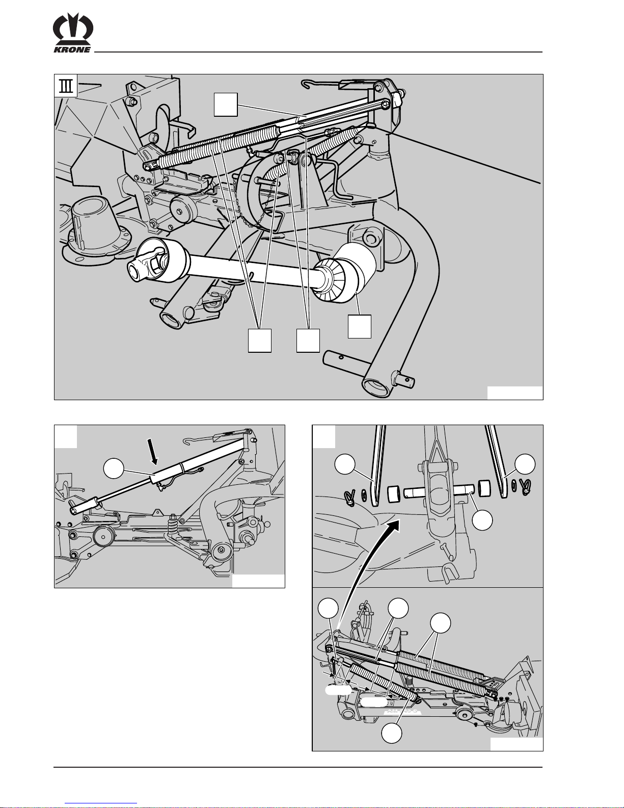
2.2 P.T.O. Shaft
The PTO shaft is slid onto the gearbox input shaft with
the friction clutch towards the disc mower, and it is
rested on the support bracket (1). The safety chains
must never be used to hold the PTO shaft. Make sure
that the locking device of the PTO shaft has snapped
into position.
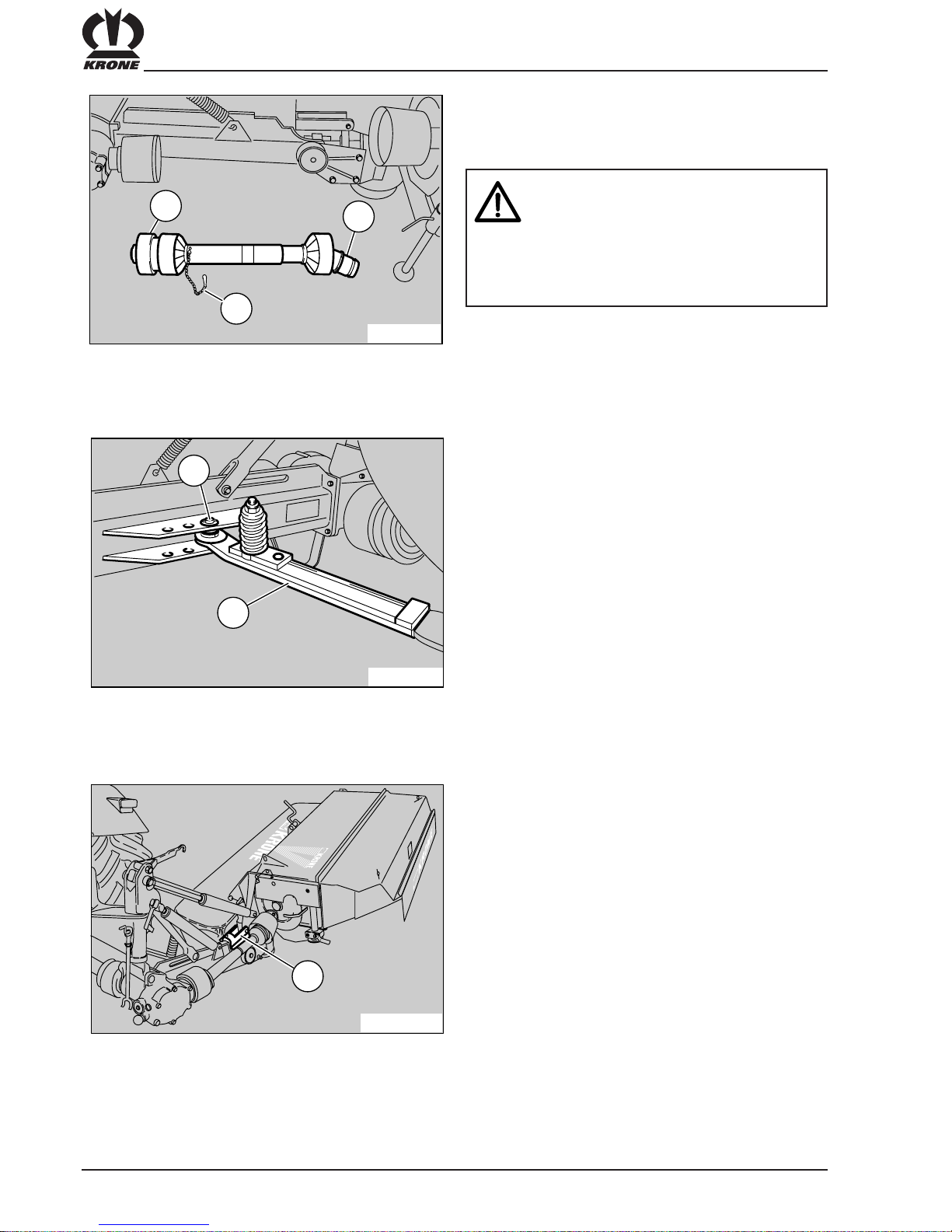
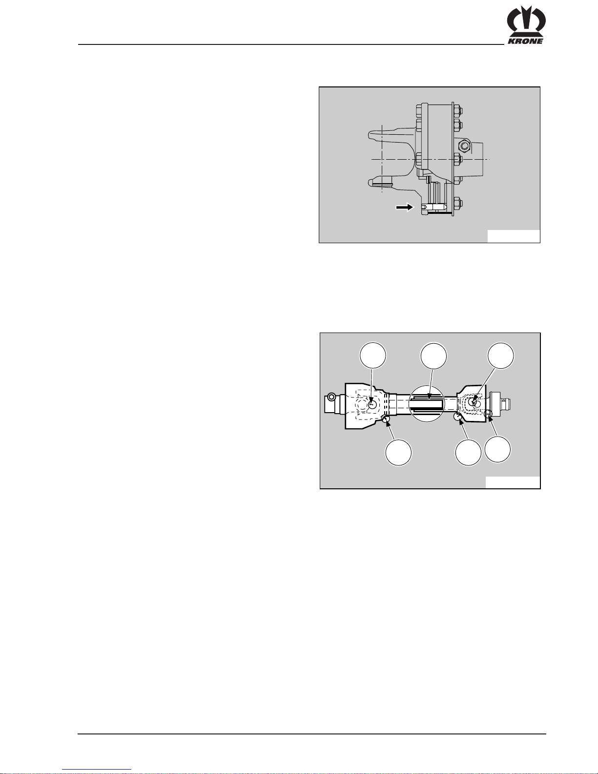
Adapting the PTO Shaft
In order to adapt the PTO shaft, the two halves of the
shaft (1) and (2) should be held next to each other in
the shortest operating position to check the overlap of
the section tubes. If the overlap is too great, the section
tubes and protecting tubes must be shortened so that
they can move freely in any operating position and do
not knock each other. The exact procedure for
shortening the PTO shaft can be found in the operating
instructions from the PTO shaft manufacturer, which
are supplied with the PTO shaft.
Check the swivel space and the free
movement space of the PTO shaft. If the
PTO shaft touches the tractor or the
attachment, this can cause damage.
Special equipment
Auxiliary gearbox for 1000 rpm power take-off shaft
Operation with a power take-off shaft speed of
1000 rpm at the tractor requires the fitting of an
auxiliary gearbox (1) on the mower unit.
- The retaining chain should be inserted
to prevent the PTO shaft guard from
rotating with the shaft.
- The chain should be inserted in such a
way that the PTO shaft has sufficient
freedom of movement in all operating
positions.
AM-0-002
1
AM-002/4
1
AM-4-054
1
2
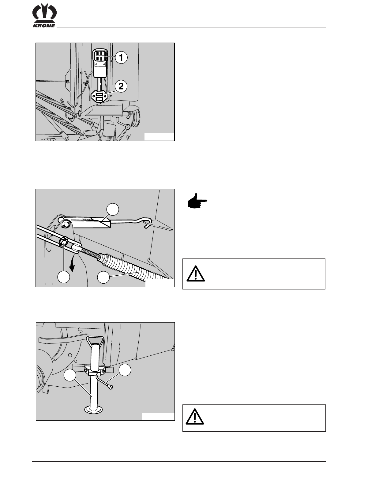
13
Make sure that the jack stand is retracted before switching on the mower.
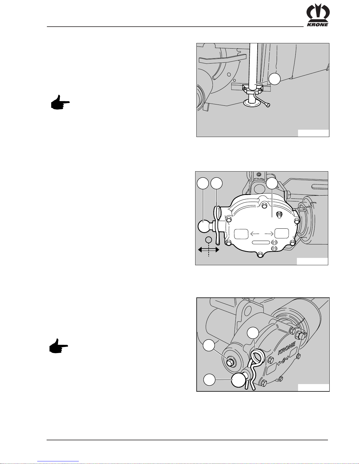
2.4 Conditioner Drive (lever change
gearbox)
The rotation speed of the tine rotor can be adjusted by
means of the change lever (1) after the retaining pin (2)
on the conditioner gearbox (3) has been removed.
The jack stand (1) must be retracted when the disc
mower is in operating position.
By turning the screw (1) with the spanner supplied, the
gear shift process with the gear change lever (3) is
made easier.
After changing the speed, make sure that
the retaining pin (2) is inserted again.
2.3 Jack Stand
KRONE
600
900
0
AM-0-007
0139-441
1 2 3
A
B
AM-0-008
1
2
3
AM-1-078
1
14
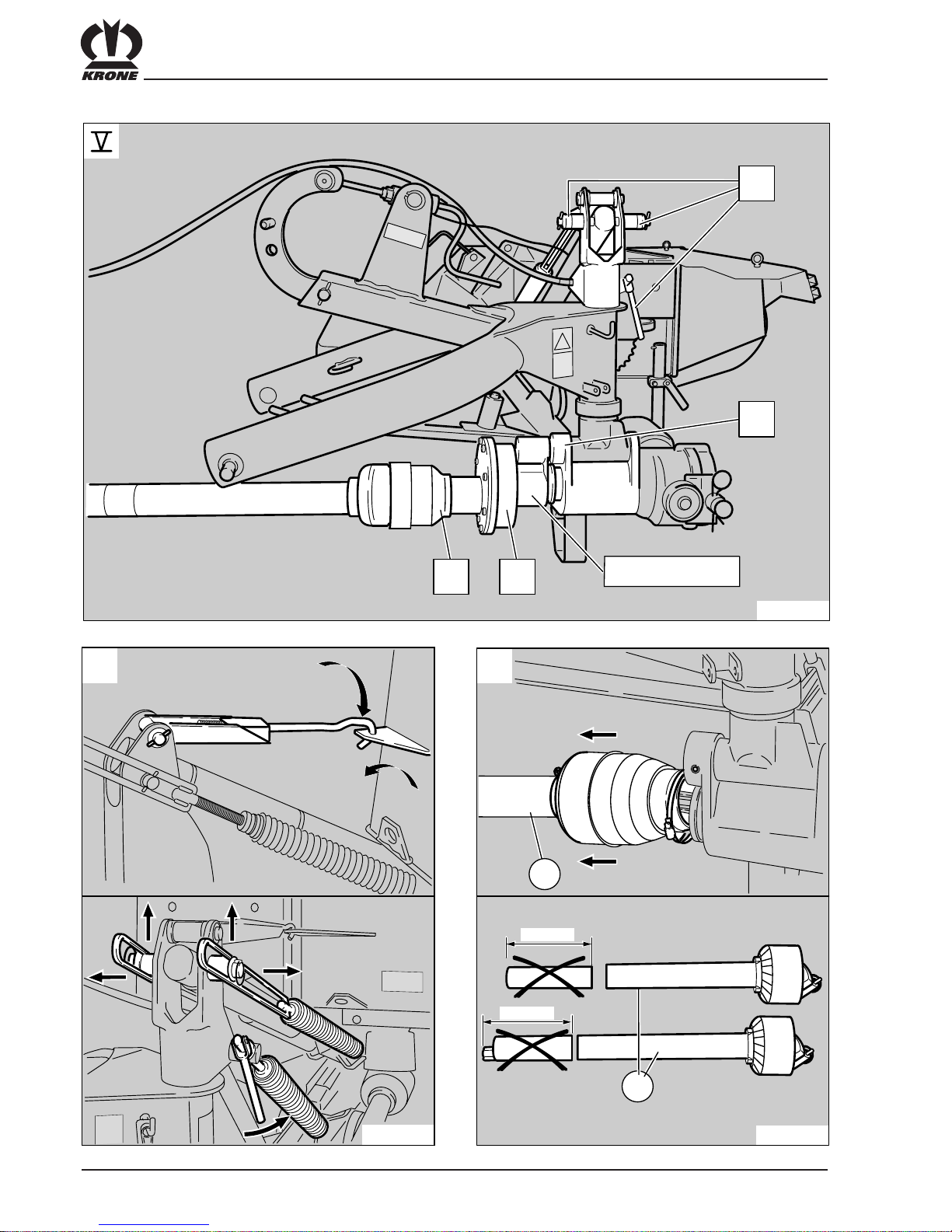
The PTO shaft for the conditioner drive is mounted with
the friction clutch (1) towards the gearbox and the freerunning end (2) towards the conditioner. Attach the
retaining chain (3) to the mower.
2.5 The angle of the mower to the tractor
The adjustment of the angle of the mower to the tractor
can be made with the breakaway safety unit (1). Basic
setting is position (2).
The retaining chain should be inserted to
prevent the PTO shaft guard from
rotating with the shaft.
The PTO shaft must only be fitted or
removed when the power take-off shaft
and the engine are turned off and the
ignition key has been removed!
2.6 Preparing to turn
When preparing to turn the tractor, simply lift the disc
mower by means of the hydraulic cylinder on the
machine until the locking mechanism (1) rests against
the catch.
AM-1-083
1
AM-1-08
2
1
2
AM-4-00
9
2
3
1
15
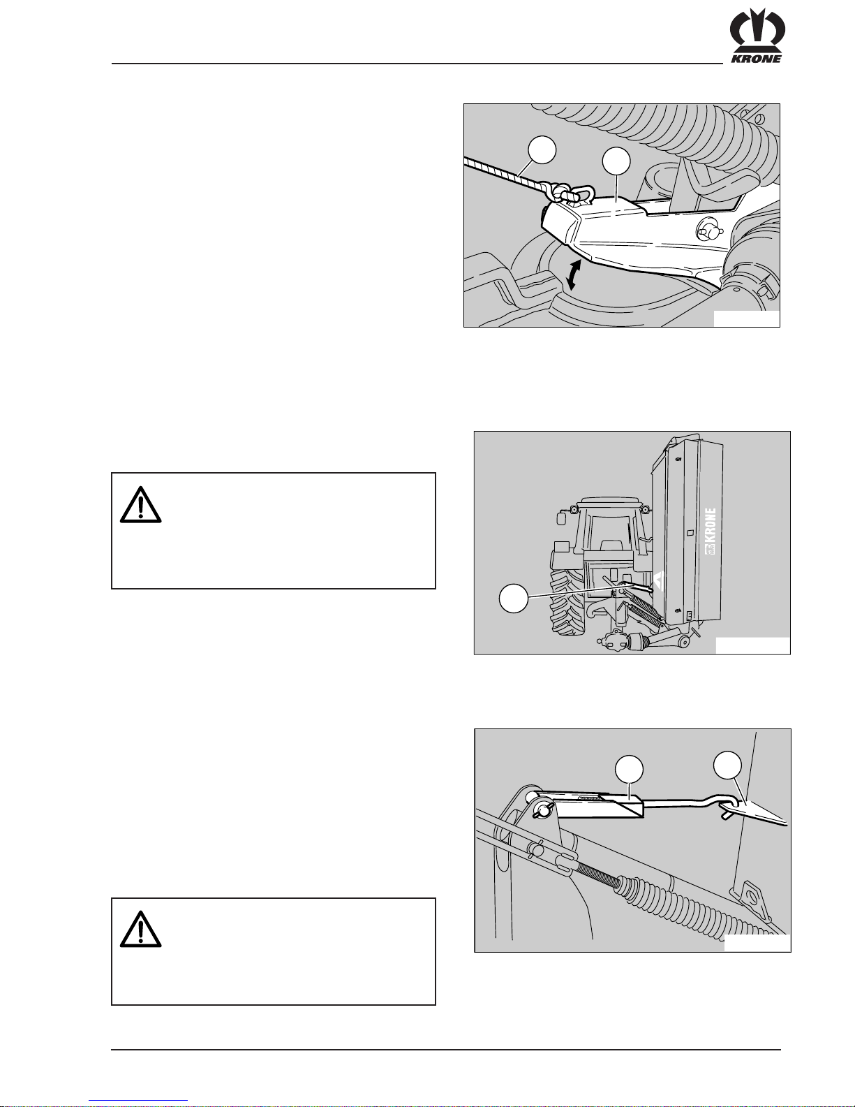
The mower unit must be secured in the transport
position. This is realised via the transport lock (1), which
has to be hooked onto the conditioner housing (2) when
the mower unit is moved to transport position. When
lifting the mower unit to transport position, hold the
synthetic cord taut until the mower unit has reached
transport position. Then release the cord so that the
hook can engage in the lug in the housing. In addition
to this, close the shut-off tap on the tractor-side of
the hydraulic hose pipe.
2.7 Transport Position
- After the drive is turned off, the
mowing discs may continue to rotate.
- It is essential to wait until the machine
is at a complete standstill before the
mower is folded up or any personnel
approach the machine!
To do this, the locking mechanism (2) is pulled from
the tractor with the synthetic cord (1) and the mower
brought to the transport position by activating the lifting
cylinder.
Adjust the transport locking device to
the ideal length.
Ensure that the transport lock is
engaged at all times.
The shut-off tap on the hydraulic hose
must be closed.
The disc mower is folded upwards for transport.
AM-1-059
1
AM-1-060
1
2
AM-1-05
8
2
1
16
The ground underneath must be level
and should be solid.
2.8 Detaching the Disc Mower from the
tractor
Always remember to attach the lights (1) to the lights
bracket (2) on the disc mower when driving on public
highways. Use standard attachable lights.
First remove the rear compensation spring (2) from the
upper bearing bolts (1) while mower unit is in transport
position, and set down on the mount.
(This makes mounting the mower unit easier!)
The compensation spring should be
detached from the bolt (1) only when in
transport position. Otherwise there is a
high risk of injury!
Do not pass between tractor and
machine while disassembling the
mower unit!
Set mower unit to transport position and lower to
ground.
Set down support leg (2) and retighten clamping
bracket (1). Detach propeller shaft from tractor and set
down on the support.
Unload the hydraulic system and uncouple hydraulic
hose from tractor - attach dust cap. Detach synthetic
cord from tractor. Unload top link arm and remove bolt
on unit side or unhook top link arm.
Detach lower link arm or disengage tail hook.
AM-1-075
AM-1-08
4
2
1
3
AM-1-061
2
1

17
When coupling the disc mower to the tractor,
it is essential that the compensation spring
(2) be pushed back onto the retaining bolt
(1) and secured with a hinge clip (3) and
washer.
Mounting the compensating spring is
only possible in transport position.
AM-0-013
3
1 2
• Only carry out work on the mower unit once the PTO shaft has been switched off, the
engine switched off and the ignition key removed. Secure the tractor against
unintentional operation and rolling away.
• Always check protective devices for damage before operation. Replace damaged
protective devices immediately. Risk of injury!
• Prop up the cutterbar when raised. Never stand under a suspended load!
• Safe operation is only guaranteed if the cutter blades are fitted according to the
instructions.
• Always check the mower unit for damaged, missing or worn cutter blades before
operation. If necessary, replace cutter blades. The same applies for retaining
components.
• To prevent unbalanced rotation, only replace missing or damaged cutter blades as
complete sets.
• Never fit cutter blades with different levels of wear to one drum/disc.
• Whenever you change cutter blades also check retaining components and replace
them if necessary.
• Move guards into position.
2.9 Safety measures before mower operation
Heavily damaged linings (see illustration)
must be replaced immediately to prevent
any risk of damage to the cutterbar.
MH-0-001
18
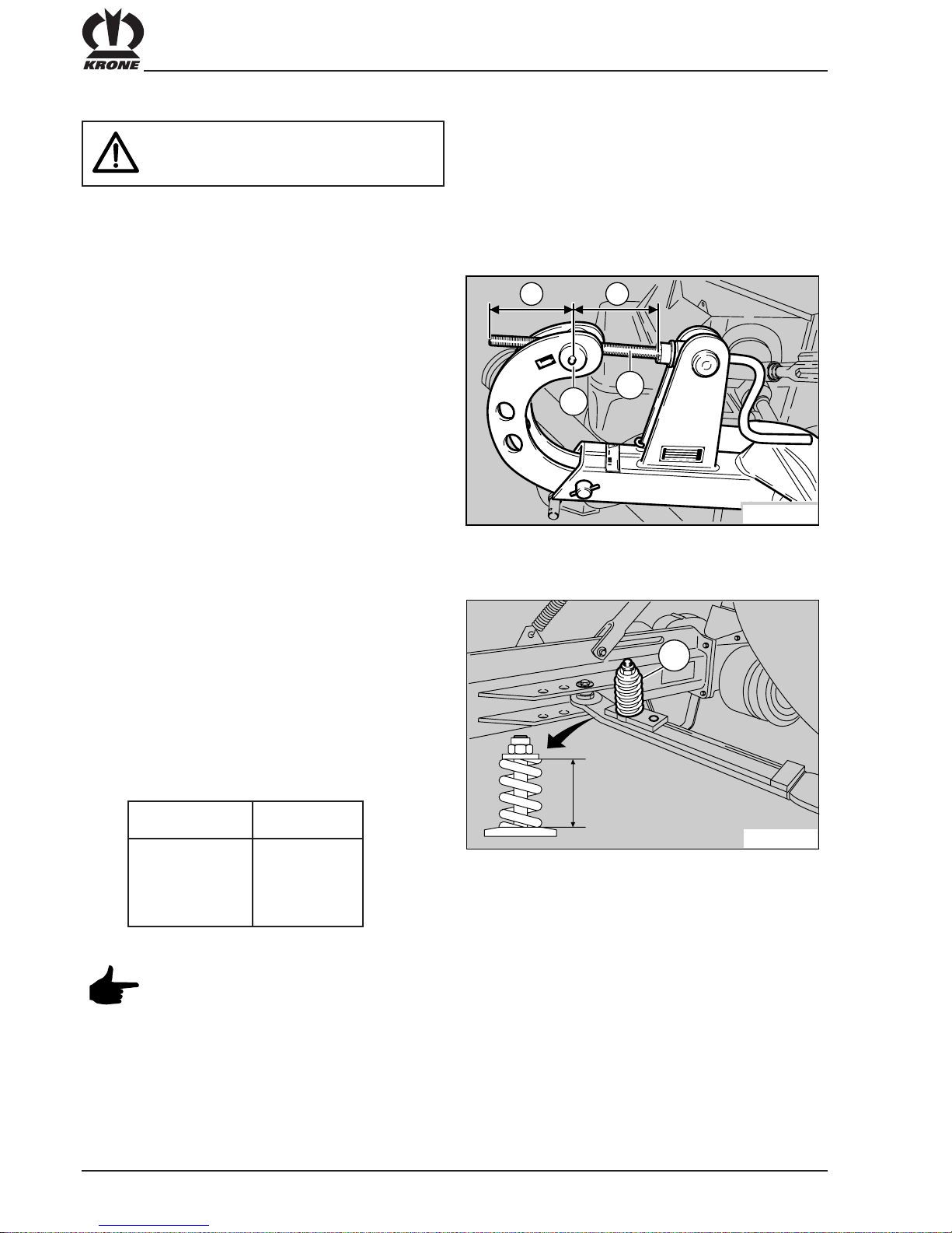
3. Adjusting the Disc Mower and Blades
3.1 Adjusting the Top Link Arm
Coupling Point
When the threaded spindle (2) on the top link arm
coupling point is in the basic position, the bolt (1) is
in the centre of the threaded spindle. The distances
marked “a” are equal.
The mower is designed and suited
to cutting grass crops that grow on
the ground.
3.2 Adjusting the Safety Breakaway Unit
To protect the disc mower from damage caused by
driving over any obstacles, the machine is equipped
with a spring loaded breakaway unit.
The most advantageous setting for the moment of
actuation is set in the factory. Should other settings
be required, adjust the length of the spring (1) as
necessary. Greater spring tension increases
the actuation moment.
Type Dimension x
AM 203 CV 81mm
AM 243 CV 80 mm
AM 283 CV 79 mm
AM 283 CV + B 79 mm
Do not set the tension in the spring
on the safety breakaway unit too high.
Risk of damage to the disc mower if the
tension is too high.
1
AM-1-063
X
1
AM- 1-06
2
2
aa
19
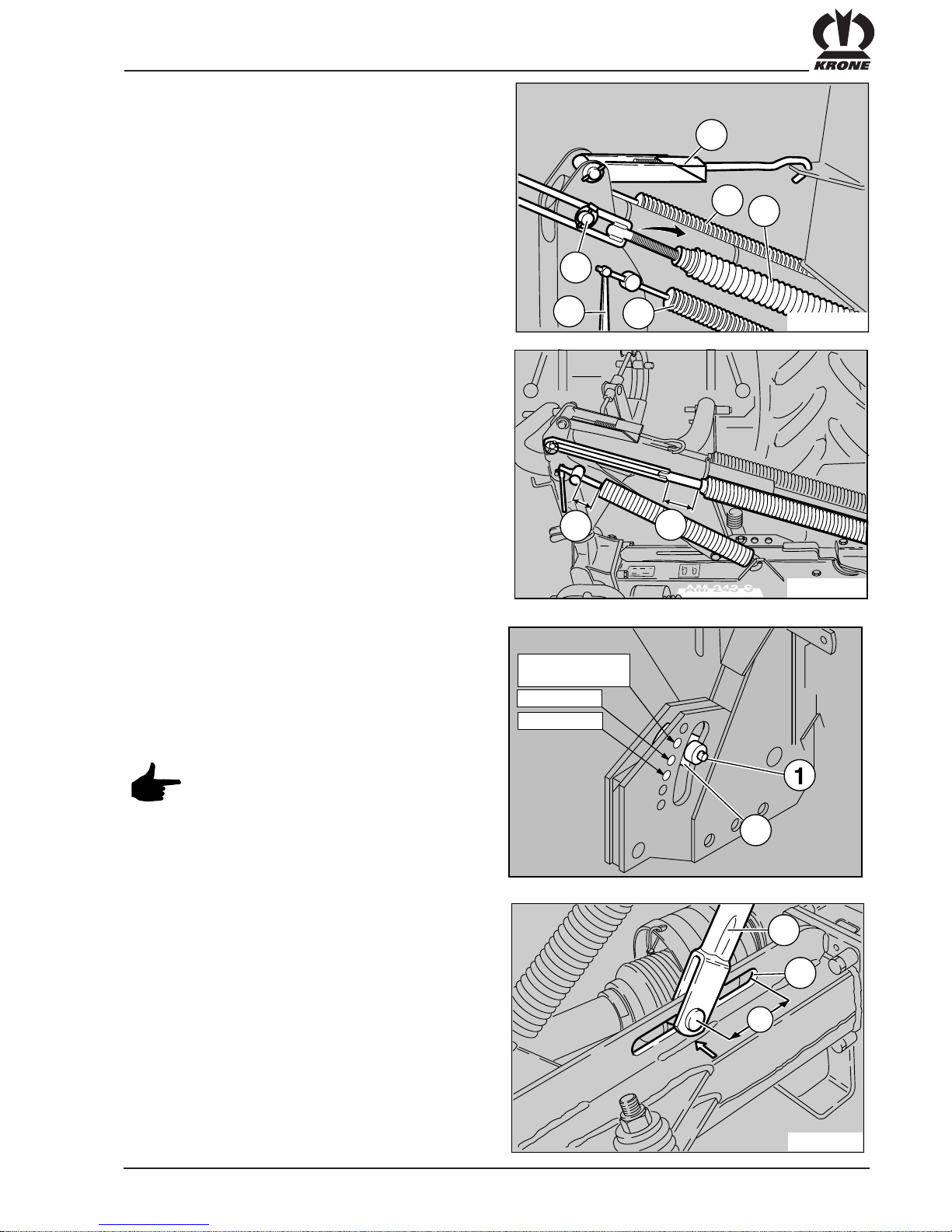
3.3 Adjusting the Compensating Spring
for the cutterbar
The three compensation springs adapt the pressure
exerted by the cutter beam on the ground below to local
conditions. In the interests of the turf, the cutter beam
should be provided with enough load compensation to
prevent jumping and subsequently leaving marks in the
ground. To make the appropriate adjustment, set the
disc mower to transport position, ensuring that the
transport lock (6) is engaged.
In this position, the compensation springs (2+3) of the
cutter beam can be taken off the pin (1), making it
possible to change their length. Shortening the length
means that the load compensation of the cutter beam is
greater.
The compensation springs (4) can be adjusted at the
spindle (5). Springs 2 and 3 provide load compensation
for the cutter beam, particularly on the outside. Spring 4
provides more load compensation on the inside.
After the compensation springs have been mounted,
resecure them on the pin with the hinge clip and washer
to prevent them slipping off.
3.5 Basic setting of the tractor lower
link arm
The best working height of the lower link arms is
achieved when the bracket (1) is fitted in the slot (2)
with a distance of a = 90 mm. This guarantees that the
mower unit will be able to adapt to uneven ground.
When preparing for turning, the cutterbar is simply lifted
by means of the hydraulic cylinder fitted to the disc
mower.
3.4 Adjusting piece for lifting cylinder
and flotation spring
The lower bearing bolt for the lifting cylinder and the
flotation spring must be locked in the correct position on
the different mower types. This adjustment is performed
at the factory and must not be changed.
Bolt (1) must be installed through lever (2).
Basic setting: distance "a" = 80 mm
distance "b" = 60 mm
AM-1-064
1
2
a
AM-1-084/
1
1
2
5
4
3
6
AM-1-084/2
a
b
AM 283 CV
AM 243 CV
AM 203 CV
AM 283 CV + B
2

20
3.6 Adjusting the Swath Width
The swath width is adjusted by means of swath
deflector plates (1) located under the swath hood
on the mower. These can be adjusted by loosening
the ring nuts (2) in the slot area. Fasten the ring nuts
securely again after making the adjustment.
1
2
AM-1-065
1
AM-1-05
3
32
AM-4-100
-3
0
+3
+6
-6
-9
+9
5
4
The weight of the disc mower would normally make it
very difficult to adjust the cutting height from the upper
link arm.The cutting height is adjusted using a crank (3).
The inclination of the disc mower and therefore also the
cutting height are adjusted at the top link arm coupling
point (1) using a threaded spindle (2).
The lower link arm must be fixed to the
tractor with chains or bars so that the
mower does not swing out during
transport or mowing!
3.7 Adjusting the cutting height
The adjustment can be checked using the inclinometer
(4) (air level) located on the conditioner housing. For
this move the mower to working position on a level area
and preset the desired cutting height on the
inclinometer.
Adjust the mower tilt by turning crank (3) until the air
level (5) of the inclinometer is in the centre between
both marks.
Indication theoretical Working
z. B. cutting height conditions
+ 6° ca. 11 cm Hight Cut
+ 3° ca. 8 cm Arable forage crop,
moist and soft ground
0° ca. 6 cm Arable forage crop
dry conditions
– 3° ca. 4 cm Normal conditions
– 6° ca. 2 cm Setting the mower to low
risk of sward damage

21
Use only original blades with the
order no. specified next to them.
Employment of wrong or unsuitable
blades may lead to accidents!
3.8 Changing Blades on the Cutting Discs
with Blade Screw Connectors
Safe and reliable operation of the mower is only
guaranteed with correctly fitted cutter blades.
Missing and damaged cutting blades cause dangerous
irregularities in the rotation. Cutting blades and fixing
bolts must therefore be checked daily.
Always inspect the mower before starting work to check
for damaged, missing or worn cutter blades. Replace
blades if necessary.
The upper section of the adjacent diagram shows
individual parts required to mount the blades and the
positions of the blades on one disc. The procedure for
mounting on the mower drums is identical. Screws (3)
and nut and washer assembly (4) are required to mount
the blades (5). Insert the screws from below through the
wear plate (2). The blades are fitted between the wear
plate and the blade disc (1). Tighten the screws from
above with nut and washer assemblies (4).
After mounting, the blades on the screws must be able
to move freely.
A number of different types of blade can be mounted on
this mower unit. The universal blade has a crossed
(twisted) shape. The blades are classed as:
Blades for
Cw rotating disc Order-No. 139-889
Ccw rotating disc Order-No. 139-888
All blades have a corresponding
designation. The arrow on the blade
should be pointing in the direction of
operation!
It is also possible to mount so-called roof shaped
blades. These can be employed identically with discs
which rotate to the left or right.
Roof shaped knife Order-No. 139-800
AM-4-032
2
3
4
1
4
1
2
5
5

22
3.9 Adjusting the Conditioner Speed
The drive speed of the conditioner rotor can be adjusted
on the conditioner gearbox (3). This enables the speed
and effect of the conditioner to be adapted to the
material concerned.
– stem crop = high conditioner speed
– leaf crop = low conditioner speed
First, the retaining pin (2) is removed. Then, the shift
lever (1) is moved out or in to select the tine rotor
speed. When the lever is pulled out (position “A”), the
conditioner speed is 600 rpm. When it is pushed in
(position “B”), the speed is 900 rpm. In the central
position of the lever, (position “0”), no torque is
transmitted.
3.10 Adjusting the Conditioner
Cover Plate
The swath cover plate is adjusted by means of a crank
handle (1) on the front of the disc mower. The setting
depends on the required degree of conditioning of the
crop.
- conditioner cover plate closer to the conditioner
rotor means stronger conditioning
- conditioner cover plate further from the
conditioner rotor means less conditioning.
The material strength of the blade screws used in the
area of the blade receptacle of may not be below
12 mm .
Missing or damaged fixing bolts / cutter
blaes must be replaced immediately!
AM-1-081
18mm
12mm
KRONE
600
900
0
AM-0-007
0139-441
1 2 3
A
B
AM-1-073
1
KRONE
A
M
2
4
3
C
V

23
3.11 Adjusting the Position of the
Conditioner Rotor to the Cutterbar
The conditioner rotor (1) of the rotor with the V-shaped
tines (2) can be adjusted to four different positions. This
is done by adjusting the distance of the conditioner from
the cutterbar.
Broken or bent tines cause irregular
rotation. Replace them immediately
when you notice them.
The locking screw (1) on the left and right sides of the
machine must be removed to make the adjustment.
The adjustment to the toothed disc (3) is made by
rotating the right hand ratchet (2). Turn the ratchet until
the desired setting is reached.
AM-1-089
2
1
2
1
AM-1-068
21

24
Fit and remove of the PTO shaft only
when the drive and the
engine is turned off and the ignition
key removed.
Before the conditioner rotor can be brought to standstill
position (position IV, pos.1), the drive PTO shaft (4)
must be completely removed, even from the conditioner
drive gearbox. Put the gearbox in the “0” position. The
PTO shaft guard can only be moved past the spacer
element (3) when the PTO shaft is detached.
Position of conditioner roller on cutter beam
I: basic position
II: position for longer crops
III: position for very long crops
IV: conditioner out of service
The conditioner may not be operated in
position IV. Detach the propeller shaft
completely from the machine. Switch
gearbox to “0” position.
AM-1-069
1
2
I
II
III
IV
3
1
AM-4-072
2
34
25
4. Maintenance
4.1 General
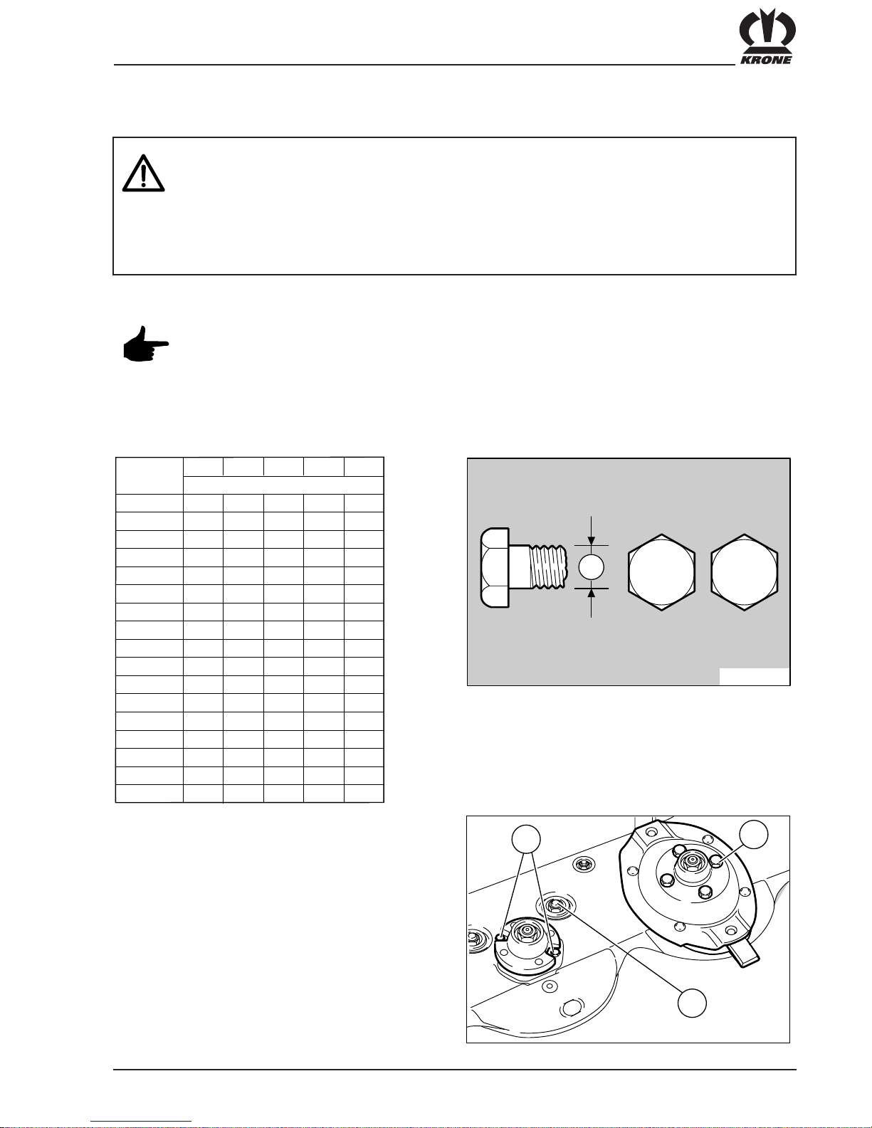
A = Thread size
(The bolt grade is visible on the bolt head.)
Torque moment MA in Nm (if not given differently).
Repair, maintenance and cleaning work must be carried out only when the drive and the
engine are turned off!
Danger, cutting discs continue to rotate!
Remove ignition key. Take measures to ensure that the tractor can not be inadvertently started
or roll away.
The transport lock must be engaged when working on the disc mower in transport position.
The shut-off tap on the hydraulic hose must be closed.
Check nuts and bolts regularly (approx. every 50 hrs.) for tightness, and tighten
if necessary!
8
.
8
1
0
.
9
A
AM-0-034
A
5.6
29
42
2,2
4,5
7,6
18
37
64
100
160
4,4
8,7
15
36
72
125
200
215
310
1050
330
350
M 4
M 5
M 6
M 8
M 10
M 12
M 14
M 14x1,5
M 16
M 16x1,5
M 20
M 24
6.8
M (Nm)
8.8 10.9
A
O
/
12.9
M 24x1,5
M 24x2
M 27
M 27x2
M 30
5,1
10
18
43
84
145
235
255
365
2450
390
3,0
5,9
10
25
49
85
135
145
210
225
730
710
122
0
135
0
180
0
195
0
2100
1150
1550
1650
1450
800
1100
1150
610
425
Tightening torque M
A
Screw cutting disc (1) MA = 49 Nm
Screw clamping disc (2) MA = 215 Nm
Hex. nut bearing housing (3) MA = 42 Nm
AM-5-066
1
2
3

26
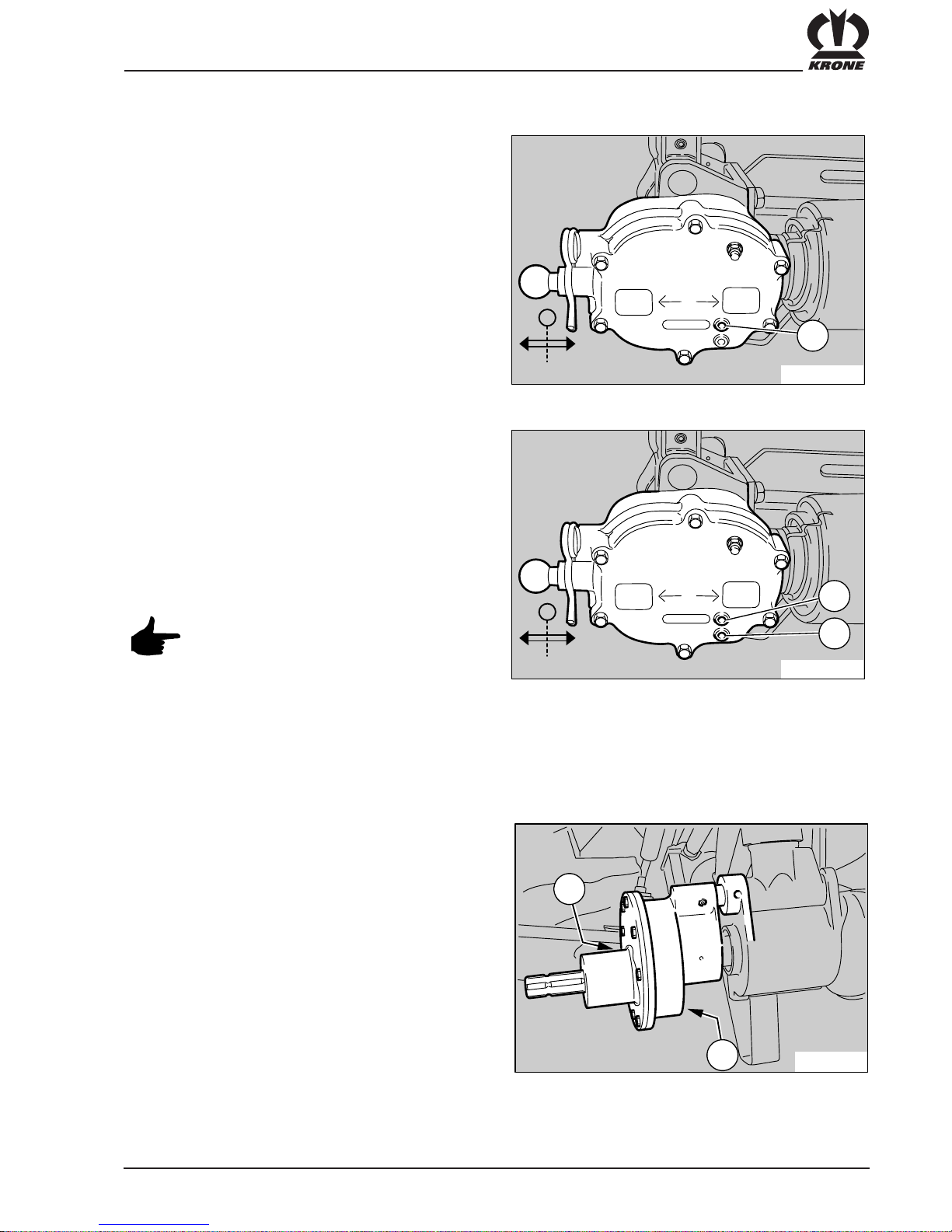
4.3 Oil Level Check and Oil Change for
Main Gearbox
Oil Change
An oil change should be carried out after approx.
350 hectares of operation. Bring the disc mower to the
transport position and secure with the transport safety
device. Unscrew the oil drain screw (2) and the oil
check screw (1) on the cutterbar. Collect the used oil
(approx. 4–6 litres) in a suitable container. When the oil
has drained, insert the oil drain screw again. Fill up to
the oil control holes (1) with new oil. Insert the oil check
screw with a ring seal. Close the oil check hole with the
screw. For oil quantities and oil types, please refer to
the chapter “Technical Data”.
Bring the disc mower into the working position before
checking the oil. Underneath the breather connection
(1) you can see the oil check hole (2) and the drain
screw (3) in the adjacent diagram. To check the oil, take
the screw out of the oil check hole. The oil in the main
gearbox must come up to the check hole. Top up with
oil if necessary.
NOTE: Change oil in the main gearbox after the first
use and then every 350 hectares.
When changing oil, take out the drain screw and the
check screw. Drain the oil (approx. 0.4 litres) into a
suitable container. Replace the drain screw and fill up to
the check hole with oil. For information on quantities and
types of oil, please refer to the chapter “Technical Data”.
Dispose of used oil in the correct way
after every oil change!
After an oil change, the used oil must be
disposed of in the correct way!
4.2 Oil Level Check and Oil Change for
Cutterbar
When checking the oil in the cutterbar,
always ensure that the cutterbar is
secured by the transport safety device.
High risk of injury!
Oil Level Check
To check the oil level in the cutterbar, first move it to
transport position and secure with the transport safety
device. Unscrew the oil level check screw (1)
on the side of the cutterbar. The oil level in the cutterbar
must reach up to the oil check hole.
Refill if necessary.
Check the oil level regularly every 100 operating hours!
AM-1-09
2
3
2
1
27
4.4 Oil Level Check and Oil Change for
the mower and conditioner drive
Oil Level Check
The gearboxes for the mower and conditioner drive
units have a common oil supply.
To check the oil level for the gearbox, twist out the
screw (1). The oil must come up to the oil check hole.
Top up with oil if necessary.
Oil Change
The oil should be changed after about 350 hectares of
operation. Unscrew the oil drain screw (2) and the oil
check screw (1) on the main gearbox. Collect the
drained oil (approx. 1 litre) in a suitable container. After
the oil has drained, insert the oil drain screw. Fill with
new oil up to the oil check hole. Close the oil check hole
with the screw. For oil quantities and oil types, please
refer to the chapter “Technical Data”.
After an oil change, the used oil must be
disposed of in the correct way!
KRONE
600
900
0
AM-0-032
0139-441
A
B
1
KRONE
600
900
0
AM-0-033
0139-441
A
B
1
2
4.5 Oil level check and oil change in the
gearbox for the 1000 rpm power take-off
Oil level check
To check the oil level, move the disc mower to working
position. Unscrew oil level check plug (1). The oil must
reach the hole of the check plug. Fill in fresh oil if
necessary.
Oil change
To change the oil, unscrew oil drain plug (2) and oil
level check plug (1). Collect the oil (approx. 0,2 litres )
in an appropriate container. Drive home the oil drain
plug again and fill fresh oil up to the hole of the oil level
check plug. For the oil quantity and quality see the
chapter "Technical Data".
NOTE: Change the oil after the first cut, then
every 350 hectares.
AM-3-095
2
1

28
4.6 Unlocking the Overload Coupling on
the Drive Shaft to the Cutterbar and on
the Conditioner Drive (Walterscheid)
The overload coupling on the cutterbar
drive can only be unlocked with the
disc mower in the transport position.
The cutterbar must be secured with the
transport bracket.
The overload coupling must be unlocked after not
being used for long periods (e.g. before the start of
harvesting). To do this tighten the nuts (1) on the
overload coupling (2) on the cutterbar drive. Fix
the PTO shaft into place. Turn the blade drum manually
in either direction. When turned, the discs in the
overload coupling separate from each other. Loosen
the nuts again after doing this until there is a clearance
between the nut and the housing of at least 3 mm.
Follow the same procedure for the overload coupling
on the conditioner drive PTO shaft.
AM-1-080
1
2
AMS-1-04
5
1
AMS-1-04
6
2
Totally release the four hex. socket head cap screws
(2) using the special key (1) supplied. the thread does
not extend over the full length of the screws, so they
cannot be turned out of the clutch.
The clutch is now ready for use.
4.7 Preparing the overload clutch for use
Firmly tighten the hexagon socket head cap screws (2)
of the overload clutch at the start of the idle period.
This will release the clutch linings from the pressure of
the cup springs and minimise the risk of sticking. The
disc clutch is bled. At the start of the next operation
hitch the mower to the tractor and switch on the pto:
the mowing discs must not rotate. If the discs should
rotate, the clutch is stuck or rusted and must first be
disassembled (remove linings from the plates and if
necessary smooth the friction surfaces using emery
paper). Then reinstall the universal drive shaft and
proceed as described above.
4.8 Bleeding the overload clutch of the
universal joint drive shaft and of the
double joint
29
4.9 Lubrication
PTO Shafts
Lubricate the PTO shafts for the main drive and the
conditioner drive at the points indicated and the time
intervals indicated.
* Apply grease to the protective tube from time to time.
AM-4-098
40h
40h
8h
20h
8h
8h
AMS-1-04
7
Storage
Before the next idle period (after the campaign or before
a prolonged period of disuse) the hex. socket head cap
screws have to be tightened firmly again.
30
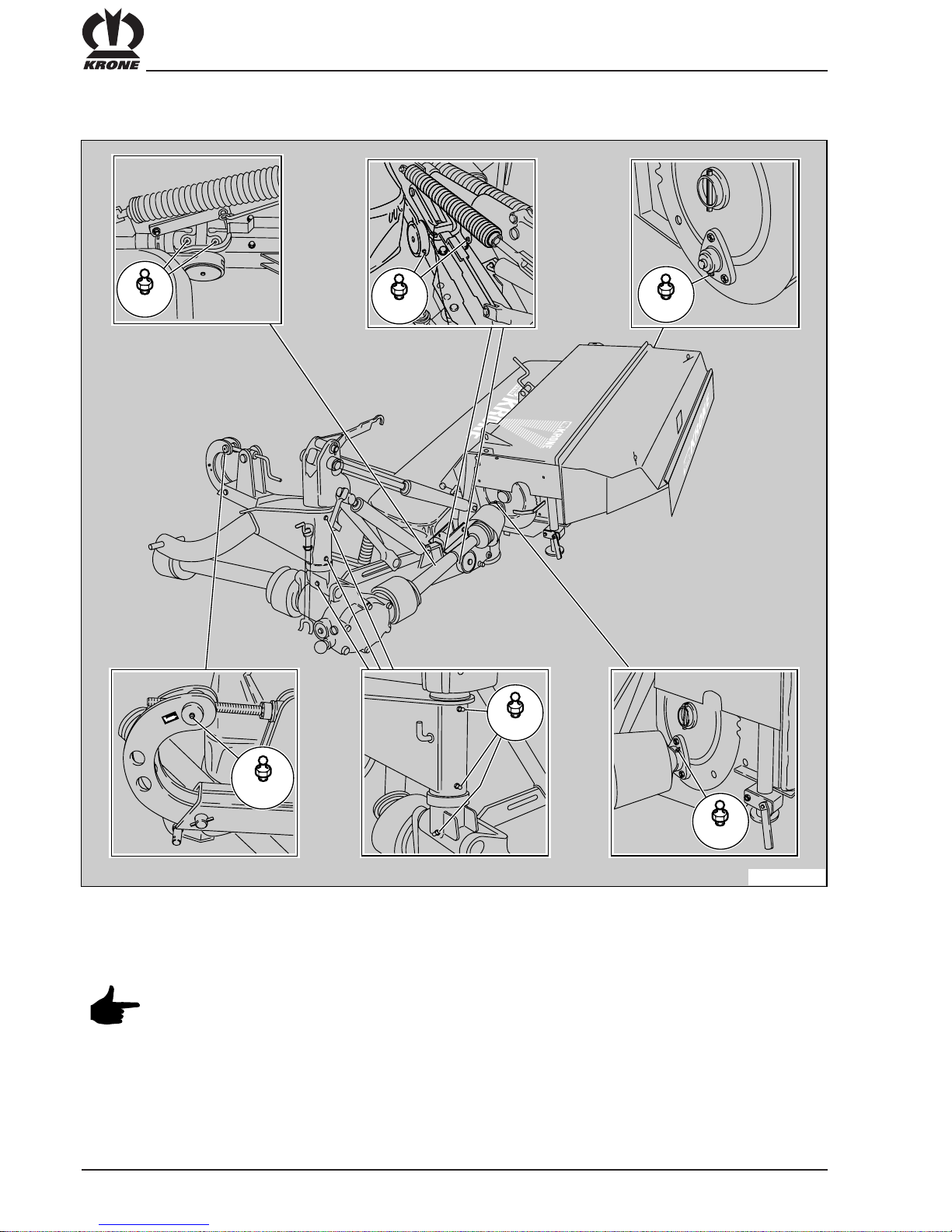
Lubrication Plan for Disc Mowers
Refer to the section entitled “Technical Data” for the recommended types of oil and lubricant
Lubricate at the lubrication points listed below after the specified number of operating hours.
AM-1-077
10 h
10 h 10 h
50 h
10 h
50 h
31
1 32
AM-0-044
AM-1-076
K
R
O
N
E
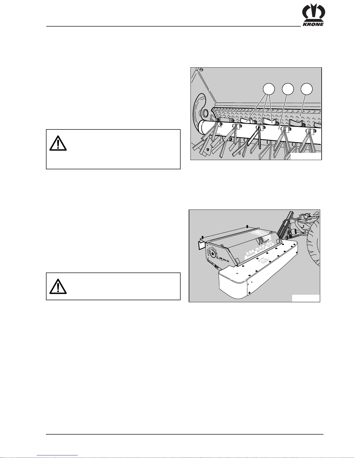
Protective Cloth Covers
The protective cloth covers (1) must be checked
regularly. Worn or damaged coth covers must be
replaced.
Protective features on the cutter bar, e.g. coth covers
and cover plates, protect from thrown up stones etc.
and from access to the dangerous part of the machine.
They must therefore be put in protective position before
work commences.
Safety first! Take no risks. Do not
experiment with imitation parts. Use only
original KRONE parts!
Conditioner
The conditioner processes the cut crop so that it can
dry faster. To ensure the best possible effectiveness, the conditioner shaft (2) must be inspected for
damaged tines before each use. Bent tines must be
straightened. Broken tines must be replaced. The
degree of processing of the crop is adjusted by means
of the distance setting of the cover plate (3) of the
conditioner (see chapter “Adjustments”).
The conditioner shaft rotates at speeds
of up to approx. 1000 rpm. Broken tines
cause dangerous irregularities in the
rotation. Therefore, broken tines must be
replaced immediately.
5. Conditioner and Protective Cloth Covers
32
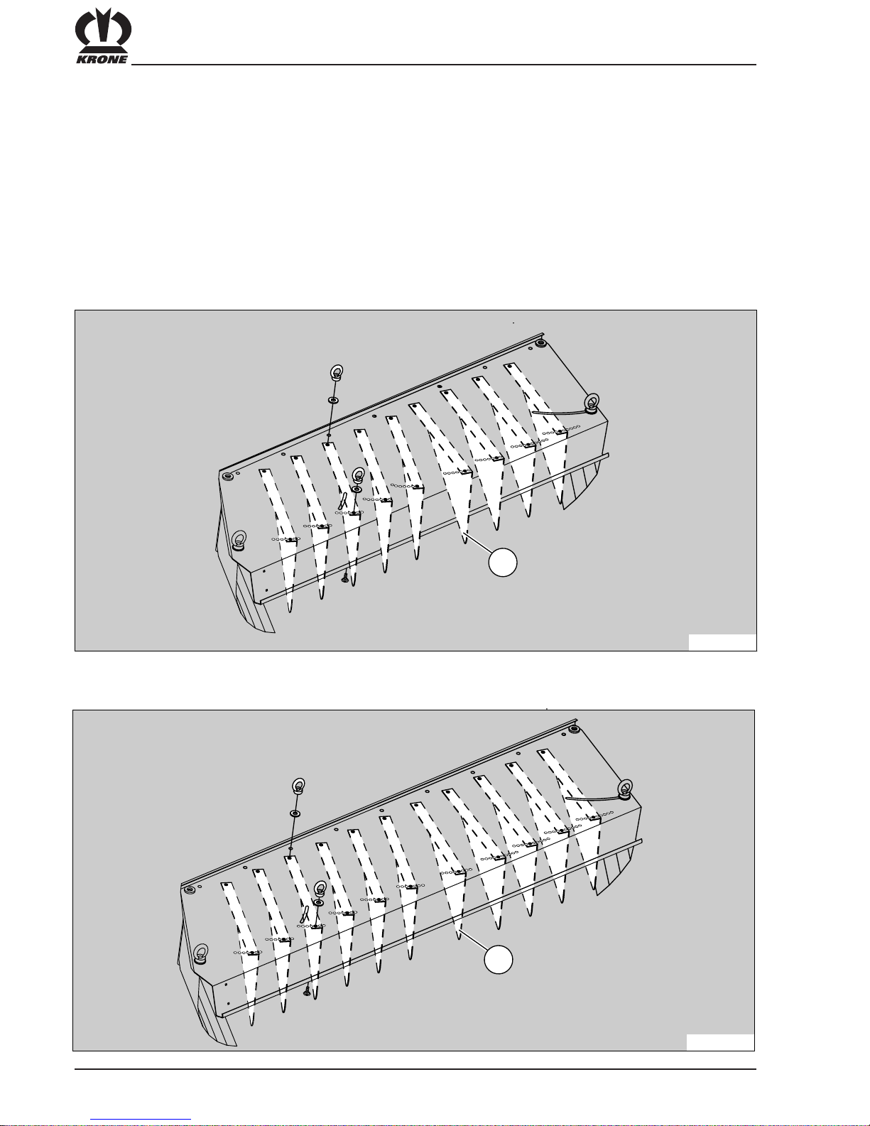
6. Wide swath hood
The disc mower AM 243 CV + B an AM 283 CV + B are fitted with a wide swath hood.
Once conditioned by the V-shaped steel tines of the conditioner rotor, the cut forage crop is evenly spread over the
entire surface which considerably speeds up the drying process.
The deflector plates (1) are secured in the marked holes when in the basic setting.
Basic setting
AM-97-0
1
1
AM 243 CV + B
AM 283 CV + B
AM-4-01
2
1
33
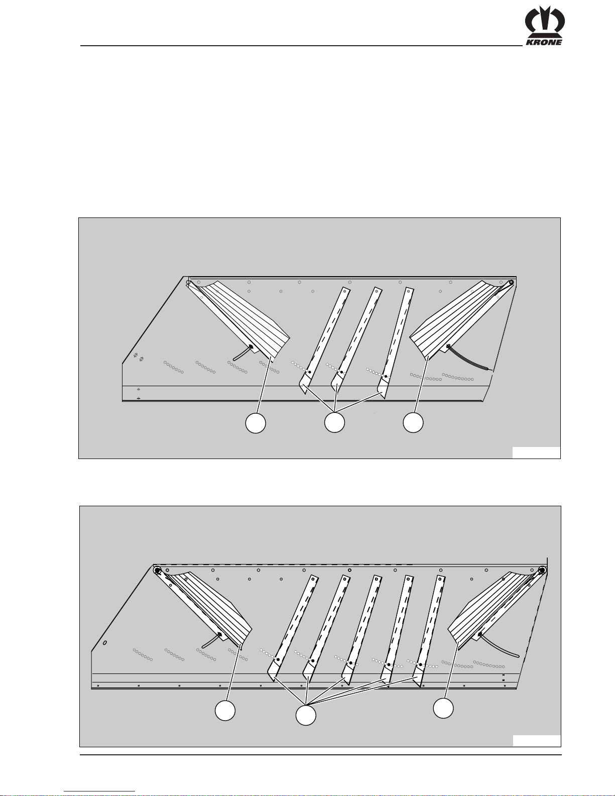
If required the grass can also be laid in a swath.
For this secure the deflector plates (1) in the marked holes and fold in the swath deflectors (2).
Change-over to swathlaying mode
AM-97-02
2
1
2
AM 243 CV + B
AM 283 CV + B
AM-4-01
3
1
2
2

34
7. Winter storage
• Store the machine in a dry place that is not near
artificial fertilizers.
• Clean the machine thoroughly from the inside and the
outside. Dirt attracts moisture and causes corrosion.
When cleaning the machine with high pressure water
jet cleaners, do not aim the water jet at the bearings.
• Check moving parts (joints etc.) for freedom of
movement, and if necessary remove them, clean
them and check for wear. If necessary, replace them
with new parts.
• Lubricate all moving parts.
• Thoroughly grease the machine.
• Grease the protective tubes of the PTO shaft to
prevent it from freezing.
• Touch up the paint work. Thoroughly treat any bare
metal with rust protection.
• Make a list of all replacement parts required, and
order them in good time. It is easier for your KRONE
dealer to obtain and fit the required parts out of the
main season. This ensures that your machine is fully
operational for the coming season.
8. Start-up after winter storage
• Wipe off the grease and oil used for machine
conservation.
• Carry out in full the steps described in the chapter on
maintenance.
• Spin the friction clutch to release sticking friction
surfaces.
• Once bled the overload clutch has to be released by
switching on the pto with the mower attached to the
tractor: the universal drive shaft must rotate freely up
to the clutch hub, whilst the mowing discs must not
rotate (also see section 4.8)
• Carefully read through the operating instructions
again.

35
Appendix
Push the special tool (1) {blade key} between the
cutter disc (4) and leaf spring (3) and press down
with one hand. Guide blade (2) onto retaining bolt
and allow the blade key to return upwards.
Disc mower AM . . . S operating manual
Appendix for
• The blades may continue to rotate after the drive has been switched off. Only
approach the mower once the working parts have come to a complete standstill.
• Only carry out work on the mower unit once the PTO shaft has been switched off,
the engine switched off and the ignition key removed. Secure the tractor against
rolling away.
• Safe operation is only guaranteed if the cutter blades are fitted according to the
instructions.
• Always check the mower unit for damaged, missing or worn cutter blades before
operation. If necessary, replace cutter blades. The same applies for retaining
components.
• To prevent unbalanced rotation, only replace missing or damaged cutter blades as
complete sets.
• Never fit cutter blades with different levels of wear to one drum/disc.
• Whenever you change cutter blades also check retaining components and replace
them if necessary.
TAKE NO RISKS!
Use only original KRONE parts!
1. Changing blades on cutter discs
with quick-release blades
1 2 3
4
AMS-1-031

36
Appendix
Check the retaining bolt according to the
instructions each time you change the
cutter blades. In case of damage or wear
replace all sets of complete blade
holders per cutting disc.
The cutter blades can be turned around
and used on both sides. When cutter
blades are missing or damaged, they
must be replaced as a complete set. This
prevents dangerous unbalanced rotation.
If the thickness of the material between the hole and the
end of the cutter blade has reduced to less than a = 7
mm, you must replace the cutter blade.
∅ 15 mm
min. 9 mm
✓
AMS-0-03
3
min. 3 mm
KRONE
139-889
KRONE
139-888
KRONE KRONE
a
AMS-1-03
2
Clockwise blade Order no.: 139 889
Anticlockwise blade Order no.: 139 888
alternativ
roof shaped knife Order no.: 139-800
(for cw and ccw rotation)
The blade key (1) is part of the shipping package. After
installation it is attached to a mount (2) at the rear hinge
pipe of the three-point frame. The open mount at the
front is secured by means of a linch pin.
AM-1-036
1
2
3
4
5
6

37
Appendix

38
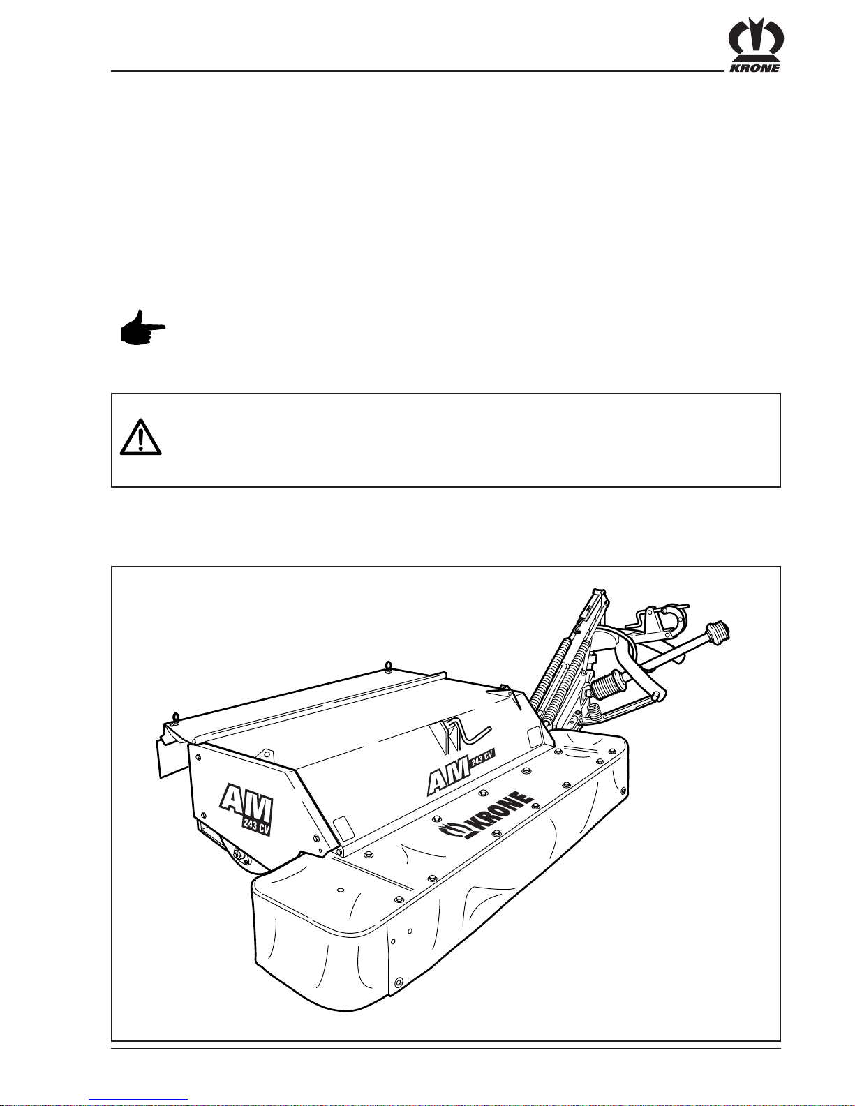
39
Supplement to
Operating Instructions
AM 203 CV / AM 243 CV / AM 243 CV + B / AM 283 CV / AM 283 CV + B
The following instructions give a detailed description of the assembly procedure for the above mentioned
KRONE disc mowers.
The mowers must only be assembled by an approved specialist workshop.
All steps described in the following instructins must be carried out in the described sequence.
The assembly of the mower must be performed with the greatest possible care. All
relevant accident prevention regulations must be complied with. Use only lifting gears
and tools of adequate dimensions. The mower must only be set into operation if all
guards and protective devices are installed. Never carry out changes yourself.
Otherwise no warranty will be assumed for resulting damage.
The operation of the mowers is described in the respective Operator's Manual.
1. Assembly Instructions

40
4
27
8
7
13
2/3
30
6
1
26
5
25
28
34
24
11
32
33
10
9
20
19
18
39
AM-4-00
0
16 15
14
23
31
22
36
21
38
37
12
29
35
17
1
+ 9
+ 6
+ 3
0
– 3
– 6
– 9
40

41
Anzahl Typ Pos. Teile-Nr. Maße
1 50 916 096 Ø 20 x 110
– 51 Ø 20 x 95
– 52 916 082 Ø 20 x 45
– 53 901 155 M 16 x 240
2 54 900 674 M 16 x 35
– 55 901 162 M 14 x 70
– 56 901 122 M 12 x 70
– 57 900 632 M 10 x 16
– 58 M 8 x 110
3 59 901 425 M 8 x 60
2 60 904 882 M 12 x 25
6 AM 203 CV
7 AM 243 CV 61 904 751 M 10 x 20
9 AM 283 CV
2 62 904 732 M 8 x 25
2 63 904 730 M 8 x 16
6 AM 203 CV
7 AM 243 CV 64 904 710 M 6 x 16
9 AM 283 CV
2 65 908 716 M 16
6 AM 203 CV
7 AM 243 CV 66 908 758 M 10
9 AM 283 CV
7 67 908 706 NM 8
8 AM 203 CV
9 AM 243 CV 68 908 704 M 6
11 AM 283 CV
2 69 909 503 M 12
– 70 ø 13 x 85
– 71 ø 5 x 40
– 72 139 567 Ro. 26,9/2,65 x 191
2 73 910 512 21 x 37 x 3
2 74 910 303 17 x 30 x3
2 75 910 347 17 x 37 x 3 Kunststoff
6 AM 203 CV
7 AM 243 CV 76 910 609 13 x 37 x 3
9 AM 283 CV
2 77 910 353 11 x 34 x 3
5 78 909 908 SKM 8
6 AM 203 CV
7 AM 243 CV 79 909 906 SKM 6
9 AM 283 CV
1 80 917 007 7,5 x 42
1 81 150 032 20 x 185
1 82 912 670 8 x 40
1 83 910 414 10,5 x 21 x 2
8 84 910 363 15 x 36 x 6
2 85 909 909 10 x 22 x 1,6
4 86 908 714 M 14
1 87 919 106 M 8 x 1
2 88 919 105 M 8 x 1

42
AM-2-004
a
9
8
AM-4-005
g
d
h
b
a
c
e
i
ia
f
da
AM-3-008
d
87
AM-3-006
b
27
28
55
84
84
86
AM-3-007
c
56
88

43
AM-4-101
-3
0
+3
+6
-6
-9
+9
40
66
83
ia
AM-2-011
g
52
10
71
73
AM-2-013
13
i
AM-2-012
h
32
71
71
51
82
81
80
AM-4-010
f
58
70
10
67
AM-4-009
e
11
AM-4-102
da

44
AM-4-015
II
p
j
r
k
q
m
n
l
l
o
AM-2-01
8
KRONE
6
7
I
KRONE
5
AM-2-01
9
76
66
61
m
AM-3-016
j
36
53
72
65
85
AM-3-017
k
31
57
77
77
57

45
o
AM-2-021
29
78
63
67
78
67
AM-2-022
3
64
79
68
p
26
AM-2-020
n
69
75
60
7
q
AM-2-023
37
25
AM-4-024
r
33
37
46
AM-2-027
s
14
AM-2-028
60 mm
80 mm
15
1618
17
16 16
35
t
AM-4-026
t
u
v
s

47
AM-2-029
20
u
19
AM-4-030
v
37
24
25

48
2
AM-2-03
3
x
AM-2-03
4
1
1
1
2
1
67
62
77
y
AM-2-035
z
AM-2-031
KRONE
KRONE
K
R
O
NE
B
K
w
x
z
z
yy
ab
KRONE
4
AM-2-03
2
w
65
54
74

49
ab
67
67
30
59
AM-2-036
50
ac
AM-2-03
8
2. Montage Getriebe für 1000er Zapfwelle
AM-4-03
7
ad
af
ae
ac
1000
1
/min
AM-4-03
9
250mm
250mm
ad
24
24

51
AM-2-041
af
AM-2-04
0
ae

52

53

KRONE: EIN STARKES PROGRAMM!
KRONE: EIN STARKES PROGRAMM!
THE BEST PROGRAMME!
LE PROGRAMME FORT!
THE BEST PROGRAMME!
LE PROGRAMME FORT!
Maschinenfabrik Bernard Krone GmbH, Heinrich-Krone-Straße 10,
D-48480 Spelle (Germany), Tel.: 05977/935-0, Fax: 05977/935-339
Internet: http://www.krone.de; e-mail: bkrone-ldm@t-online.de
SCHEIBENMÄHWERKE
DISC MOWERS /
CONDITIONER
FAUCHEUSES À DISQUES /
FAUCHEUSES À DISQUES
CONDITIONNEUSES
KREISELSCHWADER
ROTAR Y WINDROWERS
ANDAINEURS ROTA TIFS
RUNDBALLENPRESSEN
ROUND BALERS
PRESSES À BALLES RONDES
GROßPACKENPRESSEN
BIG BALERS
PRESSES À GRANDES
BALLES CUBIQUES
DREISEITEN-KIPPER
THREE-WA Y TIPPING
TRAILER
REMORQUES BASCULANTES
TRIBENNES
SELBSTFAHRENDER HOCH-
LEISTUNGS-MÄH-AUFBEREITER
SELF-PROPELLED
MOWER CONDITIONER
FAUCHEUSE AUT OMOTRICE
LADE- UND DOSIERWAGEN
SELF-LOADING AND FEEDER WAGON
ENSILEUSES-AUTOCHARGEUSES
ET ENSILEUSES AUTOCHARGEUSES-
DISTRIBUTRICES
KREISELZETTWENDER
ROTAR Y TEDDERS
FANEUSES ROT A TIVES
 Loading...