


GB
F
NL
I
E
05084
D GB F NL I E
TR CZ PL RUS H
DK S N P GR
➔ www.docuthek.com
Operating instructions
Magnetic relief valve VAN
© 2017 Elster GmbH · Edition 09.17
Translation from the German
Contents
Contents
Magnetic relief valve VAN ................
Contents ..............................
Safety.................................
Checking the usage .....................
Intended use ...........................2
Part designations ........................ 2
Installation ............................
Wiring ................................
M20 cable gland ........................3
Plug ..................................3
Socket ................................3
Closed position switch ....................4
Tightness test ..........................4
Replacing the actuator ..................5
Maintenance ...........................5
Accessories ...........................6
Pressure switch for gas DG..VC.............6
Seal set for sizes 1 – 2 ....................6
Technical data .........................7
Logistics ..............................8
Certification ...........................8
Contact ...............................8
Safety
Safety
Please read and keep in a safe place
Please read through these instructions
carefully before installing or operating. Following the
installation, pass the instructions on to the operator. This unit must be installed and commissioned
in accordance with the regulations and standards
in force. These instructions can also be found at
www.docuthek.com.
Explanation of symbols
• , , , ... = Action
▷ = Instruction
Liability
We will not be held liable for damage resulting from
non-observance of the instructions and non-compliant use.
Safety instructions
Information that is relevant for safety is indicated in
the instructions as follows:
DANGER
Indicates potentially fatal situations.
WARNING
Indicates possible danger to life and limb.
CAUTION
Indicates possible material damage.
All interventions may only be carried out by qualified
gas technicians. Electrical interventions may only be
carried out by qualified electricians.
Conversion, spare parts
All technical changes are prohibited. Only use OEM
spare parts.
Changes to edition 0.6
The following chapters have been changed:
– Installation
– Certification
GB-1
GB
F
NL
I
E
Checking the usage
2 3
Intended use
Magnetic relief valve, open when de-energized, for
the monitoring of gas valves for tightness used in
conjunction with a visual discharge unit. For purging
excess or leakage gas.
This function is only guaranteed when used within the
specified limits– see page7 (Technical data). Any
other use is considered as non-compliant.
Type code
Code Description
VAN Magnetic relief valve
T T-product
0 – 50
R
N
Nominal size DN
Rp internal thread
NPT internal thread
N Quick opening, quick closing
K
P
Q
Y
W
S
G
with visual position indicator and gold contacts
R
Mains voltage: 24VDC
100 VAC, 50/60 Hz
120VAC, 50/60 Hz
200VAC, 50/60 Hz
230VAC, 50/60 Hz
Closed position switch:
with visual position indicator
Viewing side: right
L
Electrical connection:
M20 cable gland
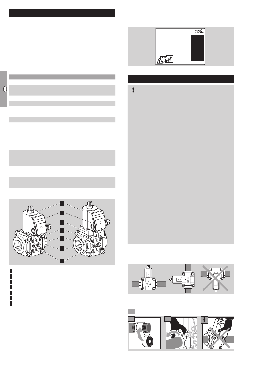
Part designations
1
3
5
6
7
4
2
VAN..S, VAN..GVAN
Solenoid actuator
Flow body
Connection box
4 Connection flange
5 Closed position switch
6 Connection parts
7 Sealing plug
Size: 1
left
Mains voltage, electrical power consumption, ambient temperature, enclosure, inlet pressure and installation position: see type label.
D-49018 Osnabrück, Germany
VAN
CE-0063BU1564
Installation
2
CAUTION
Please observe the following to ensure that the
magnetic relief valve is not damaged during installation and operation:
– Important! The gas must be dry in all conditions
and must not contain condensate.
– Sealing material and dirt, e.g. thread cuttings,
must not be allowed to get into the valve housing.
– A filter must be installed upstream of every sys-
tem.
– Do not store or install the unit in the open air.
– Dropping the device can cause permanent
damage. In this event, replace the entire device
and associated modules before use.
– Do not clamp the unit in a vice. Only secure the
flange by holding the octagon with a suitable
spanner. Risk of external leakage.
– Solenoid valves with overtravel switch and visual
position indicator VAN..SR/SL: actuator cannot
be rotated.
– Cleaning work on the solenoid actuator may not
be performed using high pressure and/or chemi-
cal cleaning agents. This can cause moisture
to get into the solenoid actuator and may lead
to a dangerous failure.
Installation position: black solenoid actuator in the
vertical upright position or tilted up to the horizontal,
not upside down.
▷
The housing must not be in contact with masonry.
Minimum clearance 20mm (0,78").
Note direction of flow.
GB-2

GB
F
NL
I
E
Wiring
WARNING
The solenoid actuator heats up during operation.
Surface temperature approx. 85°C (approx. 185°F).
Plug
LV1 (+) = black, N (–) = blue
5 6
▷ Use temperature-resistant cable (> 80°C).
Disconnect the system from the electrical power
supply.
Shut off the gas supply.
▷ Wiring to EN 60204-1.
First push
43
through the
knock-out –
then unscrew
the cover!
▷ If the M20 cable gland or plug is already fitted, it
is not necessary to push through the knock-out.
M0 cable gland
5 6
7
8 9
N
LV1
(+)
(-)
7 8
When installing two plugs
on a VAN with closed position
switch: label the sockets and
plugs to avoid confusion.
N
LV1
(+)
(-)
Socket
1 = N (–), 2 = LV1 (+)
5 6
7 9
8
1
2
GB-3

GB
F
NL
I
E
Closed position switch
LV1
1
2
3
1 32
LV1
(+)N(-)
LV1
1
2
3
1
2
3
1 32
LV1
(+)N(-)
1 32
LV1
(+)N(-)
black
white
red
▷ VAN open: contacts and closed,
VAN closed: contacts and closed.
▷ Indicator of closed position switch:
red = VAN closed, white = VAN open.
CAUTION
Please observe the following to ensure smooth
operation:
– Route valve and closed position switch cables
separately through M20 cable glands or use
two separate plugs. Otherwise, there is a risk of
interference between valve voltage and closed
position switch voltage.
▷
To make wiring easier, the connection terminal
for the closed position switch can be removed.
(+)N(-)
1 32
LV1 (+) = black, N (–) = blue
(+)N(-)
1 32
1
1
black
2
3
red
3
white
2
Tightness test
Close the gas solenoid valve.
To be able to check the tightness, shut off the
downstream pipeline close to the valve.
3
5
0
7
0
9 Tightness OK: open the pipeline.
▷
Pipeline leaking: replace O-ring on flange, see
page6 (Seal set for sizes 1 – 2). Then check
for tightness once again.
▷ Unit leaking: remove the unit and return it to the
manufacturer.
0
4
6
Open the
solenoid
valve.
8
▷ Label the plugs to avoid confusion.
1 = N (–), 2 = LV1 (+)
1
2
CPS
3
1
2
▷
Ensure that the connection terminal for the
closed position switch has been reconnected.
Finishing the wiring
1
2
3
GB-4

GB
F
NL
I
E
Replacing the actuator
43 5
VAN 2
VAN 1
VAN 1–2
▷ The actuator adapter set is enclosed with new
actuators.
VAN 2VAN 1
▷
The seals of the actuator adapter set are covered
with a non-stick coating. No additional grease
is required.
Disconnect the system from the electrical power
supply.
Shut off the gas supply.
Remove the M20 cable gland or other type of
▷
connection.
7 86
9
▷
Depending on the construction stage of the unit,
there are two different methods for replacing
the actuator:
If the unit concerned has no O-ring in this place
(arrow), replace the actuator as described here.
Otherwise, go to the next note.
10
10
▷ If the unit concerned has an O-ring in this place
(arrow), replace the actuator as described here:
▷
VAN 1: use all seals from the actuator adapter set.
VAN 2: use the small seal from the actuator
adapter set and only one of the large seals.
10
Slide seal
under the
second
groove.
11
Position new actuator.
Follow the reverse procedure when reassem-
bling.
4 Fit the M20 cable gland or plug and socket.
5 Connect the VAN to the electrical power supply,
see page3 (Wiring).
Maintenance
CAUTION
In order to ensure smooth operation, check the
tightness and function of the VAN:
– Once per year, twice per year in the case of
biogas; check for internal and external tightness,
see page4 (Tightness test).
– Check electrical installations once a year in line
with local regulations; pay particular attention
to the PEwire, see page3 (Wiring).
▷ If the flow rate has dropped, clean the strainer.
▷
We recommend replacing the seals, see
page6 (Seal set for sizes 1 – 2).
Disconnect the system from the electrical power
supply.
Shut off the gas supply.
Undo connection parts.
4 5
6
Slide seal
under the
second
groove.
11
Insert seals.
Position of the
metal ring can
be selected.
87
GB-5

GB
F
NL
I
E
9 Once the seals have been replaced, follow the
u
2
31
reverse procedure to reassemble the unit.
0 Then check the unit for internal and external
tightness, see page4 (Tightness test).
Accessories
Pressure switch for gas DG..VC
▷
The pressure switch for gas monitors the inlet
pressurepu, the outlet pressurepd and the interspace pressurepz.
p
p
▷
When retrofitting the pressure switch for gas,
see enclosed operating instructions “Pressure
switches for gas DG..C”, section entitled “Mounting the DG..C..1, DG..C..9 on valVario gas solenoid valves”.
▷
The switching point is adjustable via hand wheel.
Adjusting range
(adjusting tolerance
= ± 15% of the
scale value)
[mbar] ["WC] [mbar] ["WC]
DG 17VC 2 – 17 0.8 – 6.8
DG 40VC 5 – 40 2 – 16 1 – 2 0.4 – 1
DG 110VC 30 – 110 12 – 44 3 – 8 0.8 – 3.2
DG 300VC
▷
100 – 300
Deviation from the switching point during testing
pursuant to EN 1854 Gas pressure switches:
± 15%.
40 – 120 6 – 15 2.4 – 8
d
Mean switching
differential at min.
and max. setting
0.7 – 1.7
0.3 – 0.8
Seal set for sizes –
When retrofitting accessories or a second val-
▷
Vario control or when servicing, we recommend
replacing the seals.
A
B
C
D
E
▷ Order No. for
size 1: Order No. 74921988,
size 2: Order No. 74921989.
▷ Scope of delivery:
A 1 x double block seal,
B 1 x retaining frame (the retaining frame is not
required for VAN),
C 2 x O-rings (flange),
D 2 x O-rings (pressure switch),
for pressure test point/screw plug:
E 2x sealing rings (flat sealing), 2xprofiled
sealing rings.
C
GB-6

GB
F
NL
I
E
Technical data
Gas types: natural gas, LPG (gaseous), biogas (max.
0.1%-by-vol. H2S) or clean air; other types of gas
on request.
The gas must be clean and dry in all temperature
conditions and must not contain condensate.
Max. inlet pressure pu:
max. 500mbar (7.25psig).
Leakage rate: ≤500cm3/h (0.132gal/h).
Closing time: quick closing: <1s.
Medium and ambient temperatures:
-20 to +50°C (-4 to +122°F).
No condensation permitted.
Long-term use in the upper ambient temperature
range accelerates the ageing of the elastomer materials and reduces the service life (please contact
manufacturer).
Storage temperature: -20 to +40°C (-4 to +104°F).
Enclosure: IP65.
Valve housing: aluminium, valve seal: NBR.
Connection flanges with internal thread:
Rp to ISO7-1, NPT to ANSI/ASME.
Class A, Group 2 safety valve pursuant to
EN13611 and EN 161.
Mains voltage:
230 V AC, +10/-15%, 50/60 Hz;
200 V AC, +10/-15%, 50/60 Hz;
120 V AC, +10/-15%, 50/60 Hz;
100 V AC, +10/-15%, 50/60 Hz;
24 V DC, ±20%.
Cable gland: M20 x 1.5.
Electrical connection:
electrical cable with max. 2.5mm2 (AWG12) or
plug with socket to EN175301-803.
Power consumption:
Type Voltage Power
VAN 1
VAN 2
Switching frequency: max. 15x per minute,
duty cycle: 100%.
Power factor of the solenoid coil: cos φ = 0.9.
Closed position switch contact rating:
Type Voltage
VAN..S
12 – 250VAC,
50/60 Hz
VAN..G 12 – 30VDC 2 mA 0.1 A
24 V DC 25 W –
100 V AC 25 W (26 VA)
120 V AC 25 W (26 VA)
200 V AC 25 W (26 VA)
230 V AC 25 W (26 VA)
24 V DC 36 W –
100 V AC 36 W (40 VA)
120 V AC 40 W (44 VA)
200 V AC 40 W (44 VA)
230 V AC 40 W (44 VA)
Min. current
(resistive
load)
Max. cur-
rent (resis-
tive load)
100 mA 3 A
Closed position switch switching frequency:
max. 5x per minute.
Switching
current [A]
Switching cycles*
cos φ = 1 cos φ = 0.6
0.1 500,000 500,000
0.5 300,000 250,000
1 200,000 100,000
3 100,000 –
* Limited to max. 200,000 cycles for heating systems.
Air flow rate Q
Air flow rate Q for a pressure loss of ∆p= 1mbar
(0.4"WC)
∆p 1 mbar (0.4 "WC)
1 x VAN
Type
Air flow rate
3
Q [m
/h] Q [SCFH]
VAN 110 4.4 155.4
VAN 115 5.6 197.7
VAN 120 8.3 293.1
VAN 125 10.0 353.1
VAN 225 15.5 547.3
VAN 232 19.5 688.5
VAN 240 21.0 741.5
VAN 250 22.5 794.5
Designed lifetime
This information on the designed lifetime is based on
using the product in accordance with these operating
instructions. Once the designed lifetime has been
reached, safety-relevant products must be replaced.
Designed lifetime (based on date of manufacture) in
accordance with EN 13611, EN 161 for VAN:
Type
VAN 110 –
VAN 225
VAN 232 –
VAN 250
Switching cycles Time [years]
Designed lifetime
500,000 10
200,000 10
You can find further explanations in the applicable
rules and regulations and on the afecor website
(www.afecor.org).
This procedure applies to heating systems. For
thermoprocessing equipment, observe local regulations.
GB-7
GB
F
NL
I
E
Logistics
Transport
Protect the unit from external forces (blows, shocks,
vibration). On receipt of the product, check that the
delivery is complete, see page 2 (Part designations). Report any transport damage immediately.
Storage
Store the product in a dry and clean place.
Storage temperature: see page7 (Technical data).
Storage time: max. 6months before using for the
first time.
Packaging
The packaging material is to be disposed of in ac-
cordance with local regulations.
Disposal
Components are to be disposed of separately in
accordance with local regulations.
Certification
Declaration of conformity
We, the manufacturer, hereby declare that the product
VAN, marked with product ID No. CE-0063BU1564,
complies with the requirements of the listed Directives
and Standards.
Directives:
– 2009/142/EC – GAD (valid until 20 April 2018)
– 2014/35/EU – LVD
– 2014/30/EU – EMC
Regulation:
– (EU) 2016/426 – GAR (valid from 21 April 2018)
Standards:
– EN 13611
– based on EN161
The relevant product corresponds to the type tested
by the notified body0063.
The production is subject to the surveillance proce-
dure pursuant to Directive 2009/142/EC AnnexII
paragraph 3 (valid until 20 April 2018) and to Regulation (EU) 2016/426 Annex III paragraph 3 (valid from
21 April 2018).
Elster GmbH
Scan of the Declaration of conformity (D,GB)– see
www.docuthek.com
AGA approved
AGA
Australian Gas Association
Eurasian Customs Union
The product VAN meets the technical specifications
of the Eurasian Customs Union.
Directive on the restriction of the use of
hazardous substances (RoHS) in China
Scan of the Disclosure Table China RoHS2 – see
certificates at www.docuthek.com
Contact
Contact
If you have any technical questions, please contact
your local branch office/agent. The addresses are
available on the Internet or from ElsterGmbH.
We reserve the right to make technical modifications
in the interests of progress.
Strotheweg 1, D-49504 Lotte (Büren)
Elster GmbH
Tel. +49 541 1214-0
Fax +49 541 1214-370
hts.lotte@honeywell.com, www.kromschroeder.com
GB-8
 Loading...