


GB
F
NL
I
E
05155
D GB F NL I E
TR CZ PL RUS H
DK S N P GR
➔ www.docuthek.com
Operating instructions
Burner control unit BCU56x,580
© 2018 Elster GmbH · Edition 07.18
Cert. version 07.18
Translation from the German
Contents
Contents
Burner control unit BCU56x,580..........1
Contents ..............................1
Safety.................................1
Checking the usage .....................
Installation ............................
Replacing the power module/parameter
chip card ..............................
Cable selection.........................4
Wiring ................................4
Connection diagram ....................5
Flame control ..........................13
Adjustment ...........................14
Commissioning........................14
Manual mode .........................15
Assistance in the event of malfunction ....16
Reading off the flame signal, fault
messages and the parameters...........
Parameters and values...................23
Legend...............................5
Technical data ........................6
Designed lifetime .......................26
Logistics .............................7
Accessories ..........................7
Certification ..........................8
Contact ..............................8
Safety
Safety
Please read and keep in a safe place
Please read through these instructions
carefully before installing or operating. Following the
installation, pass the instructions on to the operator. This unit must be installed and commissioned
in accordance with the regulations and standards
in force. These instructions can also be found at
www.docuthek.com.
Explanation of symbols
• , 1 , , ... = Action
▷ = Instruction
Liability
We will not be held liable for damage resulting from
non-observance of the instructions and non-compliant use.
Safety instructions
Information that is relevant for safety is indicated in
the instructions as follows:
DANGER
Indicates potentially fatal situations.
WARNING
Indicates possible danger to life and limb.
CAUTION
Indicates possible material damage.
All interventions may only be carried out by qualified
gas technicians. Electrical interventions may only be
carried out by qualified electricians.
Conversion, spare parts
All technical changes are prohibited. Only use OEM
spare parts..
Changes to edition 0.18
The following chapters have been changed:
– Wiring
– Technical data
– Certification
GB-1

GB
F
NL
I
E
Checking the usage
Burner control units BCU 560, 565 and580 are
designed to monitor and control gas burners in intermittent or continuous operation.
The outputs for controlling the burners, e.g. for fan,
actuator and valves, are activated via a replaceable
power module. All the parameters required for operation are saved on the integrated parameter chip card.
BCU 560, BCU 565
For directly ignited burners of unlimited capacity.
BCU 580
For pilot and main burners of unlimited capacity. Pilot
and main burners can be monitored independently.
BCU..F1, BCU..F, BCU..F
Burner control units with interfaces for air control
using an air valve or actuators IC20, IC40,RBW.
BCU 565..F1, BCU 565..F, BCU 565..F
With air flow monitoring as well as pre-ventilation
and post-ventilation to control and monitor a selfrecuperative burner.
This function is only guaranteed when used within the
specified limits – see page 26 (Technical data). Any
other use is considered as non-compliant.
Type code
Code Description
BCU Burner control unit
560
565
580
Q
W
C0
C1
120VAC, 50/60 Hz
230VAC, 50/60 Hz
No valve proving system
With valve proving system
F0
F1
F2
F3
with interface for actuator IC
with interface for RBW actuators
with air valve control
D0
D1
Operation on high temperature equipment
D2
K0
K1
K2
Connection plugs with screw terminals
Connection plugs with spring force terminals
Operation with menox burner
No connection plugs
Series 560
Series 565
Series 580
Mains voltage:
Capacity control:
none
With flame control
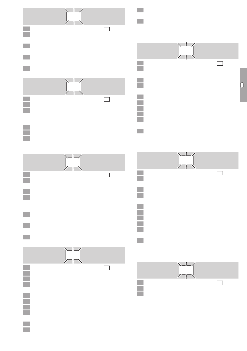
Part designations
1
2
3
4
5
6
7
1 LED display for program status and fault
messages
Reset/Information button
On/Off button
4 Type label
5 Connection for opto-adapter
6 Power module, replaceable
7 Power module type label
8 Parameter chip card, replaceable
Input voltage– see type label.
BCU
8
GB-2

GB
F
NL
I
E
Installation
1
4 5
CAUTION
Please observe the following to ensure that the
burner control unit is not damaged:
– Dropping the device can cause permanent dam-
age. In this event, replace the entire device and
associated modules before use.
Installation position: vertically upright, horizontal
▷
or tilted to the left or right.
▷ The BCU mounting is designed for horizontally
aligned 35×7.5mm DINrails.
▷
If the DINrail is aligned vertically, end clamps are
required (e.g. Clipfix35 by Phoenix Contact) to
prevent the BCU from slipping.
Replacing the power module/ parameter chip card
1 Disconnect the unit from the electrical power
supply.
2
Disengage the BCU from the DINrail.
▷
Install in a clean environment (e.g. a control
cabinet) with an enclosure ≥IP54, whereby no
condensation is permitted.
6 Remove the old parameter chip card from the
BCU and insert the new one.
▷ All the parameter settings of the BCU are saved
on the parameter chip card.
7 Slide the power module back on.
8 Reconnect the connection terminals.
9 Mount the BCU on the DINrail again.
GB-3

GB
F
NL
I
E
Cable selection
▷ Signal and control line for screw terminals max.
2.5mm2 (min.AWG24, max.AWG12), for spring
force terminals max. 1.5mm2 (min.AWG24,
max.AWG12).
▷
Do not route BCU cables in the same cable duct
as frequency converter cables or cables emitting
strong fields.
▷
The control lines must be selected in accordance
with local/national regulations.
▷
External electrical interference must be avoided.
Ionization cable, UVcable
▷ Cable lengths of 100m are acceptable if there
is no electromagnetic interference.
▷
The flame signal is adversely affected by EMCin-
fluences.
▷
Lay cables individually (with low capacitance)
and, if possible, not in a metal conduit.
Wiring
▷
Do not reverse phaseL1 and neutral conductorN.
▷
Do not connect different phases of a three-phase
current system to the inputs.
▷ Do not supply voltage to the outputs.
▷ A short-circuit on the outputs causes one of the
replaceable fuses to trip.
▷ Do not set the remote reset so that it operates
(automatically) in cycles.
▷ Wire the safety circuit inputs via contacts (relay
contacts) only.
▷
The limiters in the safety interlock (e.g. safety
temperature limiter, emergency stop) must isolate terminal 46, as well as the optional safetyrelevant inputs at terminals 65 to 68 if these are
parameterized, from the voltage supply. If the
safety interlock is interrupted, the display shows
a blinking
BCU’s control outputs are disconnected from
the electrical power supply.
▷ Connected control elements must be equipped
with protective circuits in accordance with the
manufacturer’s instructions. The protective circuit
prevents high voltage peaks which can cause
malfunctioning of the BCU.
▷
Observe the maximum duty cycle for the ignition
transformer (see manufacturer’s instructions). Adjust the minimum pause timetBP (parameter62)
correspondingly, if required.
▷
Functions of terminals 51, 65, 66, 67 and 68 are
dependent on parameter values:
Terminal Dependent on parameter
See page23 (Parameters and values).
1 Disconnect the system from the electrical power
supply.
Before wiring, ensure that the yellow parameter
chip card has been inserted in the BCU– see
page 3 (Replacing the power module/parameter chip card).
▷
Screw terminals or spring force terminals are
available for the BCU– see page27 (Accessories).
Wire as shown on the connection diagram– see
page5 (Connection diagram) onwards.
▷ Ensure a good PE (ground) wire connection to
the BCU and burners.
▷
To safeguard the safety current inputs (terminals
45 to52 and 65to68), the fuse must be de-
signed so that the sensor with the lowest switching capacity is protected.
as a warning signal and all of the
51
51 69
65 70
66 71
67 72
68 73
GB-4

+24 V
GB
F
NL
I
E
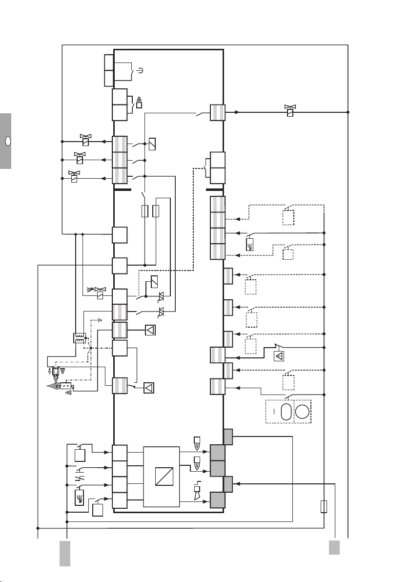
Connection diagram
BCU 560..F0
V2
V1
▷ Legend– see page25 (Legend).
3837
FS
V3
13 14 15 17 1811 1231 2
F1:T3,15AT
P69
49 50 51
HT
68
9
67
P72
66
65
61 62
P71 P73
P70
u
2
p
PZ
GZL
N
0,6 x I
Z
I
c
5 7
A
BCU 560..F0
+24 V DC
45
41 42
ϑ
46
L1
GB-5
0 V
N

+24 V
GB
F
NL
I
E
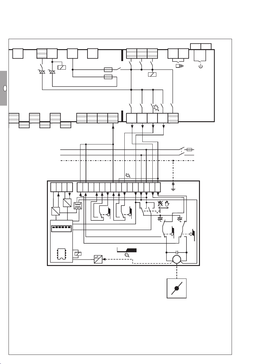
BCU 560..F
▷ Legend– see page25 (Legend).
V3
V2
V1
3837
FS
13 14 15 17 181110 1231 2
53 5449 50 51 52
F1:T3,15AH
F2:T2AH
P69
P
HT
FS
9
68
67
P72
66
65
61 62
P71 P73
P70
u
2
p
PZ
GZL
N
0,6 x I
Z
I
c
5 7
A
BCU 560..F3
+24 V DC
45
41 42
ϑ
46
L1
GB-6
N
0 V

GB
F
NL
I
E
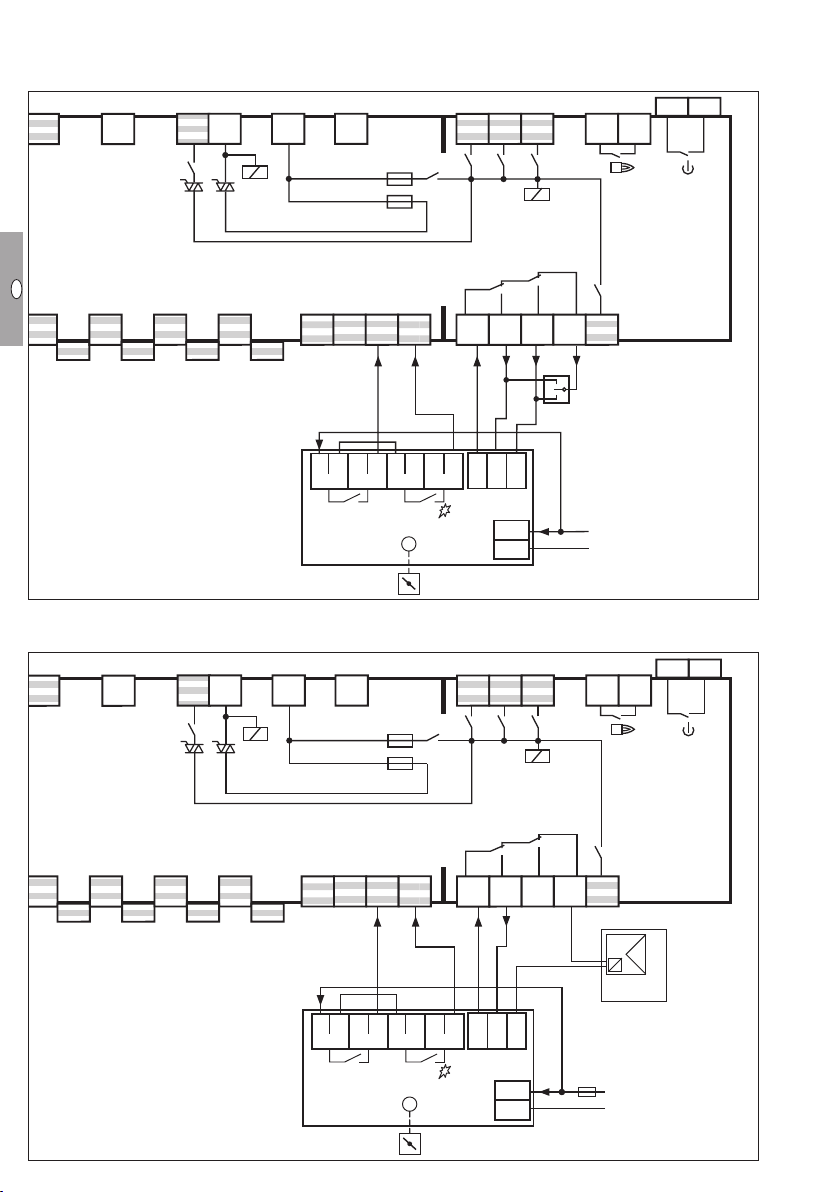
BCU 565..F
+24 V
▷ Legend– see page25 (Legend).
3837
V3
V2
V1
FS
13 14 15 17 181110 129
53 5449 50 51 52
F1:T3,15AH
F2:T2AH
P69
P
HT
47 48
68
67
P72
Air
min
PZL
FS
9
66
65
61 62
P71 P73
P70
u
2
p
PZ
GZL
N
0,6 x I
Z
I
c
5 7
31 2
A
BCU 565..F3
+24 V DC
45
42
41 44
ϑ
46
L1
GB-7
0 V
N
+24 V
GB
F
NL
I
E
BCU 580..F
▷ Legend– see page25 (Legend).
3837
V3
V2
V1
V4
FS
13 14 15 17 181110 129831 2
53 54 5749 50 51 52
F1:T3,15AH
F2:T2AH
P69
P
HT
FS
c
9
2
68
67
P72
66
65
P71 P73
P70
u
2
p
PZ
GZL
46
I
Z
I
c
5 7
BCU 580..F3
1
45
62
ϑ2
4
43
1 2
42
61
A
+24 V DC
41
ϑ1
N
0,6 x I
L1
GB-8
0 V
N

GB
F
NL
I
E
IC 0 connected to BCU..F1
▷ Parameter 40 = 1.
▷
Continuous control via three-point step controller.
7
9
FS
BCU..F1
46
47 48
66
67
68
0°
90°
F1:T3,15AH
F2:T2AH
S11
3837
13 14 15 17 181110 12
FS
90°➔0°
0°➔90°
53 54 55 56 5749 50 51 52
L1
N
PE
90°➔0°
0°➔90°
32116 674812 1115 13
PE
IC 20
S10
S1S2
S3 S4
S1
Min Max
M
GB-9
GB
F
NL
I
E
IC 0..E connected to BCU..F1
▷ Parameter 40 = 1.
▷
Continuous control via an analogue signal (directly connected to the control actuator).
7
9
FS
BCU..F1
46
47 48
66
67
68
OUT
IN
20 19 18 321674812 11
D
A
D
0°
++
A
90°
F1:T3,15AH
F2:T2AH
131516
S2
3837
13 14 15 17 181110 12
FS
90°➔0°
0°➔90°
53 54 55 56 5749 50 51 52
L1
N
0°
90°
➔
➔
OK
0°
90°
517
S1
PE
S10
PE
IC 20..E
ON
123456
µC
R
S1
Min Max
R
R
S3
S4
M
GB-10

GB
F
NL
I
E
IC 40 connected to BCU..F1
▷ Parameter 40 = 2.
▷ Set IC 40 to operating mode27, see operating
instructions Actuators IC 20, IC 40, IC 40S.
7
F1:T3,15AH
FS
BCU..F1
46
66
47 48
67
68
mA
F2:T2AH
3837
13 14 15 17 181110 129
FS
90°➔0°
0°➔90°
53 54 55 56 5749 50 51 52
L
N
22 21 20
19 18 16 15 14 12 11 10 87 54 21
A
D
AC
DC
IC 40
R..
M
GB-11
PE
GB
F
NL
I
E
RBW valve connected to BCU..F
▷ Parameter 40 = 3.
Continuous control via three-point step controller
5 7
F1:T3,15AH
FS
BCU..F2
F2:T2AH
3837
13 14 15 17 181110 129
FS
45
65
46
66
47 48
67
Continuous control via PLC
5 7
BCU..F2
COM
HI
AUTO
LO
53 54 55 56 5749 50 51 52
68
R B W
0°➔90°
RBW
90°➔0°
M
L1
N
3837
13 14 15 17 181110 129
F1:T3,15AH
FS
FS
F2:T2AH
COM
HI
AUTO
LO
45
65
46
47 48
66
53 54 55 56 5749 50 51 52
67
68
OUT
mA
+
A
D
-
PLC
+ F -
0°➔90°
RBW
M
L1
N
GB-12
GB
F
NL
I
E
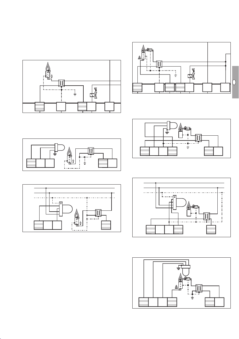
Flame control
V1
V2
V3
13 14 15 17 18
1231 2
3837
V1
V2
V3
13 14 15 17 18
3837
▷ BCU 560, 565 = 1 flame amplifier
▷ BCU 580 = 2 flame amplifiers
▷
In the case of UV control, use Elster UV sensors
for intermittent operation (UVS 1, 5, 6, 10) or
flame detectors for continuous operation (UVC1).
BCU 560, 565
Ionization/single-electrode operation:
▷ Parameter 04 = 0
Z
BCU 580
Pilot burner = single-electrode operation/
main burner = ionization:
▷ Pilot burner in single-electrode operation
▷ Ionization control for main burner
▷ Parameter 04 = 0
I
5 7
UV control:
UVS 1, 5, 6, 10
▷ Parameter 01 ≥ 5 µA
▷ Parameter 04 = 3
1
2
UVS
3
765
UVC 1
▷ Parameter 04 = 2
L
N
PE
765
4
3
2
1
UVC 1
5 7
9
1110 1298
Pilot burner = single-electrode operation/
9
1110
main burner = UVS:
▷ Parameter 01 ≥ 5 µA
▷ Parameter 04 = 3
1
2
UVS
3
Z
9 12
Pilot burner = single-electrode operation/
main burner = UVC 1:
7 865
9 12
▷ Parameter 04 = 4
L
N
PE
4
3
UVC 1
2
1
Z
9
7 865
9
Pilot burner = UVS/main burner = ionization:
▷ Parameter 02 ≥ 5 µA
▷ Parameter 04 = 5
2
3
1
UVS
I
7 865
GB-13
9 12

GB
F
NL
I
E
Pilot burner = UVC/main burner = UVC:
▷ Parameter 04 = 6
L
N
PE
2
4
3
1
4
3
2
1
7 865
UVC 1
UVC 1
9
Pilot burner = UVC/main burner = ionization:
▷ Parameter 04 = 7
L
N
PE
2
4
3
1
UVC 1
I
7 865
9
Pilot burner = UVC/main burner = UVS:
▷ Parameter 02 ≥ 5 µA
▷ Parameter 04 = 8
L
N
PE
2
4
3
1
UVC 1
1
2
UVS
3
7 865
9
Adjustment
In certain cases, it may be necessary to change the
parameters set at the factory. Using the separate
software package BCSoft and a PC opto-adapter, it
is possible to modify parameters on the BCU, such
as the pre-purge time or the behaviour in the event
of a flame failure.
▷
The software package and the opto-adapter
are available as accessories– see page27
(Accessories).
▷
Changed parameters are saved on the integrated
parameter chip card.
The factory settings are secured with a program-
▷
mable password.
▷
If the password has been changed, the end customer can look up the changed password in the
plant documentation or ask the system supplier.
Commissioning
▷
During operation, the 7-segment display shows
the program status:
Standby
00
Delay
H0
Approaching minimum capacity
A
Cooling
A0
Fan run-up time
01
Pre-ventilation
A1
Approaching maximum capacity
A
Delay
H1
Pre-purge
P0
Pre-purge
P1
Approaching ignition capacity
A
Valve check
Safety time 1 t
02
Safety time 1 t
A2
Flame proving period 1
03
Flame proving period 1
A3
Burner 1 operation
04
Burner 1 operation
A4
Burner 2 waiting time
05
Delay
A5
Delay time during burner 2 waiting time
H5
Safety time 2 t
06
Safety time 2 t
A6
Flame proving period2t
07
Flame proving period2t
A7
Burner 2 operation
08
Burner 2 operation
A8
Delay
H8
Device Off
––
Remote control (with OCU)
U I
Data transfer (programming mode)
(blinking dots) Manual mode
0.0.
SA1
SA1
SA2
SA2
FS2
FS2
WARNING
Risk of explosion! Check the system for tightness
before commissioning.
Do not start the BCU until the parameter settings
and wiring are correct and the faultless processing
of all input and output signals has been ensured.
1 Switch on the system.
▷ The display indicates
Switch on the BCU by pressing the On/Off but-
ton.
▷ The display indicates
▷
If the display blinks (fault), reset the BCU by
pressing the Reset/Information button.
GB-14
––
00
.
.

GB
F
NL
I
E
BCU 560..F0
Apply the start-up signal to terminal1.
▷ The display indicates
▷ The display indicates
01
.
. The gas valves open
02
and the burner ignites. Safety time1 starts to
elapse.
▷
The display indicates 03 during flame proving
period1.
▷
The display indicates 04. The burner is in op-
eration.
BCU 560..F, BCU 565..F
▷ If the air actuator is activated externally for cool-
ing in the start-up position, the display indicates
.
A0
Apply the start-up signal to terminal1.
▷ The display indicates 01 or A1 if the air actuator
has been activated.
▷ The display indicates 02 or A2 if the air actuator
has been opened. The gas valves open and the
burner ignites. Safety time1 starts to elapse.
▷
The display indicates 03 during flame proving pe-
riod1 or A3 if the air actuator has been opened.
▷ The display indicates 04 or A4 if the air actuator
has been opened. The burner is in operation.
BCU 580..F
▷ If the air actuator is activated externally for cool-
ing in the start-up position, the display indicates
.
A0
Apply the start-up signal to terminal1.
▷ The display indicates 01 or A1 if the air actuator
has been opened.
▷
The display indicates 02 or A2 if the air actua-
tor has been opened. The gas valves open, the
pilot burner (burner1) ignites and safety time1
starts to elapse.
▷
The display indicates 03 during flame proving pe-
riod1 or A3 if the air actuator has been opened.
▷ The display indicates 04 or A4 if the air actuator
has been opened. The pilot burner is in operation.
▷ The display indicates 06 or A6 if the air actuator
has been opened. The main burner (burner2)
ignites and safety time2 starts to elapse.
▷
The display indicates 07 during flame proving pe-
riod2 or A7 if the air actuator has been opened.
▷ The display indicates 08 or A8 if the air actuator
has been opened. The main burner is in operation. The controller enable signal has been issued.
▷ Manual mode is terminated by switching off the
BCU or in the event of a power failure.
▷
Parameter 67 = 0: Manual mode unlimited in
time. The burner control unit may continue to
be operated manually in the event of failure of
the control system or the bus.
▷ Parameter 67 = 1: The BCU will terminate Man-
ual mode 5minutes after the last time the Reset/
Information button is pressed. It switches to the
start-up position/standby (display
).
00
1 Switch on the BCU while holding the Reset/
Information button. Hold the Reset/Information
button until the two dots in the display start to
blink.
If the Reset/Information button is pressed briefly,
▷
the current step in Manual mode is shown.
▷
If the Reset/Information button is pressed for
>1s, the BCU proceeds to the next program
step.
Keep pressing the Reset/Information button (for
>1s at a time) until the BCU has reached the
Burner operation program step (BCU560, 565=
display
/BCU580= display
0.4.
0.8.
).
BCU..F1 with IC 0
▷
Following the burner operating signal (BCU56x=
display
0.4.
, BCU580= display
0.8.
), actuator
IC20 can be opened and closed as required.
Press the Reset/Information button.
▷
If the button continues to be held down, the
actuator opens further until it reaches the position for maximum capacity.
▷ The display indicates
▷
Once the button has been released, the butterfly
with blinking dots.
A.
.
valve stops in the relevant position.
4 Press the Reset/Information button again.
▷
If the button continues to be held down, the
actuator closes further until it reaches the position for minimum capacity.
▷ The display indicates
with blinking dots.
A.
.
▷ A change of direction takes place each time the
button is released and pressed again. When the
butterfly valve has reached its final position, the
dots disappear.
BCU..F1 with IC 40, BCU..F with RBW or
frequency converter
▷ Following controller enable (BCU56x= display
0.4.
, BCU580 = display
0.8.
), it is possible to
move between the positions for maximum and
Manual mode
minimum capacity on a binary basis.
▷ For adjustment of the burner control unit or for
fault-finding.
▷
In Manual mode, the BCU operates independently of the status of the inputs for start-up
signal (terminal1), controlled air flow (terminal2)
and remote reset (terminal3). The function of the
controller enable/emergency stop input (terminal46) is retained.
GB-15

GB
F
NL
I
E
Assistance in the event of malfunction
DANGER
Electric shocks can be fatal! Before working on
possible live components, ensure the unit is disconnected from the power supply.
Fault-clearance must only be undertaken by authorized trained personnel.
▷ Faults may be cleared only using the measures
described below.
▷
If the BCU does not respond even though all
faults have been remedied: remove the unit and
return it to the manufacturer for inspection.
? Faults
! Cause
• Remedy
? The 7-segment display does not light up.
! Mains voltage is not applied.
• Check the wiring, apply mains voltage (see type
label).
! Ignition cable has no contact in the ignition trans-
former.
• Check the connection.
! Ignition cable has short-circuited to ground.
• Check installation, clean the spark electrode.
• If the fault cannot be remedied by doing this,
remove the unit and return it to the manufacturer
for inspection.
? Start-up without flame – no gas supply – the
display blinks and indicates
or
02
.
A 2
! A gas valve does not open.
• Check the gas pressure.
• Check voltage supply to the gas valve.
! There is still air in the pipe, e.g. after installation
work has been carried out or if the system has
not been in operation for a long period.
• “Purge” the pipeline and reset the BCU.
• If the fault cannot be remedied by doing this,
remove the unit and return it to the manufacturer
for inspection.
0 2
0 3
0 6
0 7
0 1
? The display blinks and indicates
!
The BCU has detected an incorrect flame signal
without the burner having been ignited (extraneous signal).
• Direct the UV sensor exactly at the burner to be
monitored.
!
The UV tube in the UV sensor is defective (service
life ended) and issues a continuous flame signal.
• Replace the UV tube, see UV sensor operating
instructions.
! Flame signal through conductive ceramic insula-
tion.
• Increase value of parameter01 in order to adapt
the switch-off threshold of the flame amplifier for
burner1.
0 2
? Start-up – no ignition spark – the display
blinks and indicates
02
A 1
A 2
or
A 2
01
or
.
! The ignition cable is too long.
• Shorten it to 1m (max.5m).
! Gap between spark electrode and burner head
is too great.
• Adjust gap to max. 2mm.
!
Ignition cable has no contact in the terminal boot.
• Screw the cable on firmly.
A 1
A 2
.
? Start-up– flame burning – nevertheless, the
display blinks and indicates
pilot burner/burner (burner1) or
on the main burner (burner).
! Flame failure on start-up.
• Read off the flame signal.
▷
If the flame signal is lower than the switch-off
threshold for the flame signal from burner1 (parameter01) or burner2 (parameter02), this may
be attributable to the following causes:
!
The set value for the cut-off sensitivity is too high.
!
Short-circuit on the flame rod as the result of
soot, dirt or moisture on the insulator.
A 3
A 6
2
! Flame rod not correctly positioned at the flame
edge.
! Terminal boot not properly connected to flame
rod.
! Gas/air ratio incorrect.
!
Flame not contacting burner ground as the result
of excessively high gas or air pressure.
! Burner or BCU not (adequately) grounded.
! Short-circuit or discontinuity on the flame signal
cable.
! Soiled UV sensor.
! UV sensor wiring is defective.
• Remedy fault.
or
A 7
3
6
on the
or
7
GB-16

GB
F
NL
I
E
0 5
A 5
1 0
? The display blinks and indicates
05
or
A 5
! The BCU has detected an incorrect flame sig-
nal without burner2 (main burner) having been
ignited (extraneous signal).
• Direct the UV sensor exactly at the burner to be
monitored.
! The UV tube in the UV sensor is defective (service
life ended) and issues a continuous flame signal.
• Replace the UV tube, see UV sensor operating
instructions.
! Flame signal through conductive ceramic insula-
tion.
• Increase value of parameter02 in order to adapt
the switch-off threshold of the flame amplifier for
burner2.
0 8
?
Operation– flame burning – burner interrupted– the display blinks and indicates
or
.
A8
! Flame failure during operation or during delayed
controller enable.
• Read off the flame signal, see page23 (Read-
ing off the flame signal, fault messages and the
parameters).
▷
If the flame signal is lower than the switch-off
threshold for the flame signal from burner2
(parameter02), this may be attributable to the
following causes:
!
The set value for the cut-off sensitivity is too high.
!
Short-circuit on the flame rod as the result of
soot, dirt or moisture on the insulator.
A 8
08
! Flame rod not correctly positioned at the flame
edge.
! Gas/air ratio incorrect.
!
Flame not contacting burner ground as the result
of excessively high gas or air pressure.
! Burner or BCU not (adequately) grounded.
! Short-circuit or discontinuity on the flame signal
cable.
! Soiled UV sensor.
• Remedy fault.
.
? The display blinks and indicates
! Actuation of the remote reset input is faulty.
! Too many remote resets. More than 5resets
have been conducted within the last 15minutes,
either automatically or manually.
! Consecutive fault caused by a previous fault
whose actual cause has not been remedied.
• Pay attention to previous fault messages.
• Remedy cause.
▷ The cause will not be remedied by performing a
reset every time a fault lock-out occurs.
• Check whether remote reset complies with
standards (EN746 allows resetting only under
supervision) and correct if necessary.
▷ The BCU may only be reset manually under su-
pervision.
• Press the Reset/Information button on theBCU.
? The display blinks and indicates
! Too many restarts for burner1. More than 5re-
starts initiated within the last 15minutes.
• Check burner setting.
• Press the Reset/Information button on theBCU.
1 1
1 2
? The display blinks and indicates
! Too many restarts for burner2. More than 5re-
starts initiated within the last 15minutes.
• Check burner setting.
• Press the Reset/Information button on theBCU.
2 0
? The display blinks and indicates
! Voltage is applied to the output at terminal56.
• Check the wiring and ensure that the voltage
outputs and inputs have the same polarity and
are not reversed.
! The unit has suffered an internal fault in the power
module.
• Replace the power module.
10
11
12
20
.
.
.
.
GB-17

GB
F
NL
I
E
2 1
? The display blinks and indicates
! Inputs 51 and 52 are activated simultaneously.
• Check input 51.
▷
Input 51 may only be activated if the valve is open.
• Check input 52.
▷ Input 52 may only be activated if the valve is in
the position for ignition capacity.
21
.
2 2
? The display blinks and indicates
! Actuator IC 20 has been wired incorrectly.
• Check the wiring. Wire the outputs and inputs
of connection terminals 52–55 as shown in
the connection diagram – see page 9 (IC
20 connected to BCU..F1).
! The unit has suffered an internal fault in the power
module.
• Replace the power module.
.
22
2 3
? The display blinks and indicates
! The butterfly valve position is not constantly sig-
nalled back to theBCU.
• Check the wiring and ensure that the position
for max. capacity/ignition capacity/Closed of
the butterfly valve is constantly signalled back
via terminal52.
23
.
2 4
? The display blinks and indicates
! Faulty activation via the bus. Requirements for
“Open” and “Close” set simultaneously.
• Ensure that “Open” and “Close” are not activated
simultaneously.
24
.
3 0
? The display blinks and indicates
! Abnormal data change in the parameters set for
theBCU.
• Reset the parameters to their original values using
the BCSoft software.
• Establish the cause of the fault to avoid repeat
faults.
• Ensure that the cables have been installed prop-
erly– see page4 (Cable selection).
.
30
• If the measures described above do not help,
remove the unit and return it to the manufacturer
for inspection.
3 1
? The display blinks and indicates
! Abnormal data change in the parameters set for
theBCU.
• Reset the parameters to their original values using
the BCSoft software.
• Establish the cause of the fault to avoid repeat
faults.
• Ensure that the cables have been installed prop-
erly– see page4 (Cable selection).
• If the measures described above do not help,
remove the unit and return it to the manufacturer
for inspection.
31
.
3 2
? The display blinks and indicates
! Supply voltage too low or too high.
• Operate the BCU in the specified mains voltage
range (mains voltage +10/-15%, 50/60Hz).
! The unit has suffered an internal fault.
• Remove the unit and return it to the manufacturer
for inspection.
.
32
3 3
? The display blinks and indicates
! Faulty parameterization.
• Check parameter settings using BCSoft.
! The unit has suffered an internal fault.
• Remove the unit and return it to the manufacturer
for inspection.
33
.
43
? The display blinks and indicates
! Faulty actuation of the air valve.
! The unit has suffered an internal fault.
• Remove the unit and return it to the manufacturer
for inspection.
.
34
GB-18
GB
F
NL
I
E
53
? The display blinks and indicates
! The bus module and control unit are incompat-
ible.
• Check the bus system and PLC for Profibus
compatibility.
! Bus module does not support the selected func-
tion.
• Check the setting of parameter75.
35
.
3 6
? The display blinks and indicates
! Voltage is applied to the device outputs.
• Check the wiring and ensure that the voltage
outputs and inputs have the same polarity and
are not reversed.
! The unit has suffered an internal fault.
• Replace the power module.
• Remove the unit and return it to the manufacturer
for inspection.
36
.
• Change parameter56 (Measurement timeVp1)
using BCSoft.
• If the fault cannot be remedied by doing this,
remove the unit and return it to the manufacturer
for inspection.
4 1
? The display blinks and indicates
! The downstream gas solenoid valve (V2) is leak-
ing.
• Check the downstream solenoid valve.
! The gas pressure switch DGpu/2 for the tightness
test has been set incorrectly.
• Check the inlet pressure.
• Set DGpu/2 to the correct inlet pressure.
• Check the wiring.
! The test period is too long.
• Change parameter56 (Measurement timeVp1)
using BCSoft.
• If the fault cannot be remedied by doing this,
remove the unit and return it to the manufacturer
for inspection.
41
.
3 9
? The display blinks and indicates
! Short-circuit on one of the outputs of the safety
circuit.
• Check the wiring.
• Check fine-wire fuseF1 (3.15A, slow-acting,H).
▷
The fine-wire fuse can be replaced once the
power module has been removed.
• Then check the faultless processing of all input
and output signals.
! The unit has suffered an internal fault in the power
module.
• Replace the power module.
.
39
? The display blinks and indicates
! One of the burner-side gas solenoid valves (V2/
V3) is leaking.
• Check the burner-side solenoid valves.
! The gas pressure switch DGpu/2 for the tightness
test has been set incorrectly.
• Check the inlet pressure.
• Set DGpu/2 to the correct inlet pressure.
• Check the wiring.
! The test period is too long.
• Change parameter56 (Measurement timeVp1)
using BCSoft.
• If the fault cannot be remedied by doing this,
remove the unit and return it to the manufacturer
for inspection.
4 2
.
42
4 0
? The display blinks and indicates
! The gas solenoid valve V1 is leaking.
• Check the gas solenoid valve V1.
! The gas pressure switch DGpu/2 for the tightness
test has been set incorrectly.
• Check the inlet pressure.
• Set DGpu/2 to the correct inlet pressure.
• Check the wiring.
! The test pressure between V1 andV2 has not
decreased.
• Check the installation.
! The test period is too long.
.
40
? The display blinks and indicates
! Faulty pressure switch signal.
• Check the wiring and setting of the pressure
switch.
4 4
.
44
GB-19

GB
F
NL
I
E
4 5
• Check the wiring.
? The display blinks and indicates
! Faulty valve actuation, reversed valve connection.
• Check the wiring of the solenoid valves.
45
.
5 1
? The display blinks and indicates
! Interruption of signal at the “Safety interlock/
Controller enable/Emergency stop” input (terminal46).
• Check voltage supply to terminal46.
51
.
5 2
? The display blinks and indicates
! The BCU is permanently reset by remote reset.
• Check voltage supply to terminal3.
• Apply voltage to terminal3 only for reset, approx.
1second.
.
52
5 3
? The display blinks and indicates
! The time between two starts is less than the
min.time (timingcycle).
• Comply with the min. timing cycletz
tz
[s] = (tVZ + 0.6 × t
min
Example:
Pre-ignition time t
1st safety time on start-up t
tz
= (2 + 0.6 × 3) + 9 = 12.8 s
min
VZ
= 2 s
SA1
SA1
= 3s
53
min
) + 9
.
:
5 7
? The display blinks and indicates
! Faulty actuation of the input at terminal44. The
BCU is prompted to go into menox mode, even
though there is no signal for high temperature
operation (>750°C) at terminal49.
• Check the wiring.
8 9
9 8
? The display blinks and indicates
,
96
! System fault – the BCU has performed a safety
shut-down. The cause may be a unit defect or
abnormal EMC influence.
• Ensure that the ignition cable has been installed
properly– see page4 (Cable selection).
• Ensure that the EMC regulations for the sys-
tem are satisfied– particularly for systems with
frequency converters – see page 4 (Cable
selection).
• Reset the unit.
• Disconnect the burner control unit from the mains
supply and then switch it on again.
• Check mains voltage and frequency.
•
If the measures described above do not help, the unit
has probably suffered a hardware defect– remove the
unit and return it to the manufacturer for inspection.
9 4
9 5 9 6
9 9
or
98
.
99
.
57
,
,
89
94
95
9 4
,
5 4
? The display blinks and indicates
! Faulty feedback signal of the control element
position for ignition capacity.
• Check wiring from central actuator to BCU (ter-
minal66).
• Check whether parameter 71=20 (LDS ignition
position check).
.
54
5 6
? The display blinks and indicates
! Faulty wiring of multi-flame control. A flame signal
and an incorrect flame signal are sent to the BCU
at the same time.
56
.
? The display blinks and indicates
! The inputs are supplied with different phases of
a three-phase current system.
• Check the wiring and ensure that the device and
the inputs are supplied with the same phase.
9 7
? The display blinks and indicates
! No PCC.
• Insert compatible PCC.
! Contact problems on the power module.
• Remedy contact problems.
! Power module is defective.
• Replace power module.
GB-20
94
.
.
97

GB
F
NL
I
E
• If the measures described above do not help, the
unit has probably suffered a hardware defect –
remove the unit and return it to the manufacturer
for inspection.
0
? The display blinks and indicates
! The “no flow” state check of the air pressure
switch has failed.
• Check the function of the air pressure switch.
Before the fan is switched on, there must be no
high signal at the input for air monitoring (terminal47) when air monitoring is activated.
.
0
2 3
6
? The display blinks and indicates
5, 6, 7
! The input signal for the air pressure switch has
dropped out during start-up/operation at program stepX (02to08).
!
Failure of the air supply at program stepX
• Check the air supply.
• Check the air pressure switch setpoint.
or
7
.
8
4
8
2
,
3, 4
5
.
,
1
A
? The display blinks and indicates
! The operating check of the air pressure switch
has failed. The air monitor, depending on the
parameter setting for input 47 or 48 (P15 and
P35), has not switched after fan start-up.
• Check the air monitor wiring.
• Check the air pressure switch setpoint.
• Check the function of the fan.
.
1
? The display blinks and indicates
! No “Minimum capacity reached” signal from
actuator.
• Check the butterfly valve and the function of the
limit switches in the actuator.
• Check the wiring.
• Check the actuator.
• If the fault cannot be remedied by doing this,
remove the unit and return it to the manufacturer
for inspection.
.
A
P
? The display blinks and indicates
! The input signal (terminal48) for the air pressure
switch has dropped out during pre-purge.
• Check the air supply during the purging process.
• Check the electrical wiring of the air pressure
switch.
• Check voltage supply to terminal48.
• Check the air pressure switch setpoint.
8 0
? The display blinks and indicates
! Burner 1 flame amplifier is defective.
• Remove the unit and return it to the manufacturer
for inspection.
8 5
? The display blinks and indicates
! Burner 2 flame amplifier is defective.
• Remove the unit and return it to the manufacturer
for inspection.
P
80
85
.
? The display blinks and indicates
! No “Maximum capacity reached” signal from
actuator.
• Check the butterfly valve and the function of the
limit switches in the actuator.
• Check the wiring.
• Check the actuator.
• If the fault cannot be remedied by doing this,
remove the unit and return it to the manufacturer
for inspection.
.
? The display blinks and indicates
! No “Ignition capacity reached” signal from actua
tor.
• Check the butterfly valve and the function of the
limit switches in the actuator.
.
• Check the wiring.
• Check the actuator.
• If the fault cannot be remedied by doing this,
remove the unit and return it to the manufacturer
for inspection.
A
A
.
A
.
A
-
GB-21

GB
F
NL
I
E
E
? The display blinks and indicates
! Internal communication with bus module has
suffered a fault.
• Connected control elements must be equipped
with protective circuits in accordance with the
manufacturer’s instructions.
▷
This prevents high voltage peaks which can
cause malfunctioning of the BCU.
• Use suppressed terminal boots (1kΩ).
• If the fault cannot be remedied by doing this,
remove the unit and return it to the manufacturer
for inspection.
! The bus module is defective.
• Replace the bus module.
.
E
! One of the external flame detectors detects an
extraneous signal (an incorrect flame signal).
• Eliminate extraneous signal.
! Incorrect voltage supply to terminal67.
• Check voltage supply to terminal67.
! Parameter 45 has been set incorrectly.
• Check whether multi-flame control is required.
If not, set parameter45 to0.
F 2
? The display blinks and indicates
! One of the external flame detectors does not
detect a flame signal during the safety time.
• Check voltage supply to terminal68.
.
F2
F 3
? The display blinks and indicates
! Incorrect or defective parameter chip card (PCC).
• Only the intended parameter chip card is to be
used.
• Replace defective parameter chip card.
.
1
? The display blinks and indicates
! No input signal for the valve proof of closure
switch (POC) during standby.
• Check the wiring.
▷ Mains voltage must be supplied to the BCU (ter-
minal45) if the valve is closed and no voltage is
to be applied if the valve is open.
• Check that the proof of closure switch and valve
function perfectly, replace defective valves.
1
.
8
? The display blinks and indicates
! The BCU is receiving no information as to wheth-
er the POC switch contact is still open.
• Check the wiring.
• During start-up, mains voltage must be supplied
to the BCU (terminal45) if the valve is closed and
no voltage is to be applied if the valve is open.
• Check that the proof of closure switch and valve
function perfectly, replace defective valves.
.
8
F 1
? The display blinks and indicates
F1
.
? The display blinks and indicates
! One of the external flame detectors does not
detect a flame signal during the flame proving
period.
• Check voltage supply to terminal68.
F 4
? The display blinks and indicates
! One of the external flame detectors does not
detect a flame signal during operation.
• Check voltage supply to terminal68.
0
? The display blinks and indicates
! No connection established between BCU
andPLC.
• Check the wiring.
• Check the PLC program to ensure that the net-
work name and IPconfiguration of the BCU are
valid.
• Switch on the PLC.
1
? The display blinks and indicates
▷ Fault occurs on devices with fieldbus communi-
cation with address check (P80=1) only.
! An invalid or incorrect address has been set on
the bus module.
• Assign the correct address (001toFEF) to the
bus module.
GB-22
F3
F4
0
1
.
.
.
.

GB
F
NL
I
E
• Press the Reset/Information button again for
2
? The display blinks and indicates
! The bus module has received an incorrect con-
figuration from thePLC.
• Check whether the correct GSD file was im-
ported.
2
.
2s to go to the next item of information (fault
message, parameter value).
▷
Each time the button is released, the corresponding fault message or parameter value is displayed.
▷ To go to one of the last fault messages or to a
parameter more quickly, hold the Reset/Infor
mation button pressed down for longer (≥2s).
▷ If the button is pressed briefly, the display indi-
-
cates what parameter number is currently being
displayed.
3
? The display blinks and indicates
▷ Fault occurs on devices with fieldbus communi-
cation with address check (P80=1) only.
! The BCU has been assigned an invalid network
name or has not been assigned a network name
in thePLC.
• Assign a network name corresponding to the
default network name (e.g. bcu-560-xxx) or use
the default name as a suffix of an individually
assigned name in the following form: “individualpartofnamebcu-560-xxx”.
▷
“xxx” stands for the address set on the device
(e.g. 4a5).
3
.
4
▷
The normal program status is displayed again
approx. 60seconds after the last time the button is pressed.
▷
If an operator-control unit OCU is connected,
information about the flame signal intensity, fault
messages and parameter values can only be
queried using the OCU, see page 27 (Accessories).
Parameters and values
Pa-
Parameter name
rameter
Parameter value
No.
Burner 1 flame signal switch-off threshold
01
2 – 20 = µA
Burner 2 flame signal switch-off threshold
02
2 – 20 = µA
Flame control
0 = Ionization
? The display blinks and indicates
4
.
! PLC in STOP position.
• Check whether the PLC can be started.
Reading off the flame signal, fault
messages and the parameters
▷
During operation (BCU 56x = display
BCU580= display
0 8
), information about the
flame signal intensity, the last 10fault messages
and the parameter values can be read off by
repeatedly pressing the Reset/Information button.
Display Information
F1
F2
E0
to
E9
01
to
99
* Only on BCU 580
Flame signal intensity:
Burner 1
*
Burner 2*
Last fault message
to
tenth to last fault message
Parameter 01
to
parameter 99
• Press the Reset/Information button for approx.
2s until the display indicates
.
F1
• Release the button. The display indicates the
flame signal intensity inµA.
0 4
,
1 = UVS
2 = UVD
3 = Ionization 1 and UVS 2
04
4 = Ionization 1 and UVD 2
5 = UVS 1 and ionization 2
6 = UVD 1 and UVD 2
7 = UVD 1 and ionization 2
8 = UVD 1 und UVS 2
High temperature operation
0 = Off
2 = Intermittent operation with UVS
06
3 = Continuous operation with ionization/UVD
5 = menox intermittent
Burner 1 start-up attempts
1 = 1 start-up attempt
07
2 = 2 start-up attempts
3 = 3 start-up attempts
Burner 2 start-up attempts
1 = 1 start-up attempt
08
2 = 2 start-up attempts
3 = 3 start-up attempts
Restart
0 = No
1 = Burner 1
2 = Burner 2
09
3 = Burner 1 and burner 2 (pilot and main burners)
4 = Max. 5 times in 15 min. for burner1
5 = Max. 5 times in 15 min. for burner2
6 = Max. 5 times in 15 min. for burners 1 and2
GB-23

GB
F
NL
I
E
Pa-
Parameter name
rameter
Parameter value
No.
Low air pressure protection
0 = Off
15
1 = With safety shut-down
2 = With fault lock-out
Delayed low air pressure protection
0 = Off
16
1 = On
Safety time during operation
19
0; 1; 2 = Time in seconds
menox pre-ventilation time t
28
0 – 250 = Time in seconds
Pre-purge time tPV
34
0 – 6000 = Time in seconds
VLM
Air flow monitoring during pre-purge
0 = Off
35
1 = With safety shut-down
2 = With fault lock-out
Pre-ventilation time t
36
0 – 250 = Time in seconds
Post-ventilation time tNL
39
0 – 3 = Time in seconds
VL
Capacity control
1 = IC 20
2 = IC 40
40
3 = RBW
4 = Frequency converter
5 = Air valve
Running time selection
0 = Off; checking the positions for min./max.
capacity
1 = On; for approaching the positions for min./
max. capacity
41
2 = On; for approaching the position for
maximum capacity
3 = On; for approaching the position for
minimum capacity
Running time
42
0 – 250
= Time in seconds
Low fire over-run
0 = Off
43
1 = Up to minimum capacity
Controller enable signal delay timetRF
44
0 – 250 = Time in seconds
Air actuator control
0
= Opens on external activation
1
= Opens with valve V1 (1st stage)
2
= Opens with valve V2 (2nd stage)
48
3
= Controller enable following operating signal
or in standby
4
= Opens with V4 burner 1
Air actuator can be activated externally on
start-up
49
0 =
Cannot be activated
1 =
Can be activated externally
Air actuator in the event of fault
0 =
50
Cannot be activated
1 =
Can be activated externally
Pa-
Parameter name
rameter
Parameter value
No.
Valve proving system
0 = Off
1 = Tightness test before start-up
51
2 = Tightness test after shut-down
3 =
Tightness test before start-up and after shut-down
4 = Proof of closure function
Measurement time Vp1
56
0 – 3600 = Time in seconds
Valve opening time 1 tL1
59
2 – 25 = Time in seconds
Minimum operating time tB
61
0 – 250
=
Minimum pause time tBP
62
0 – 3600
Switch-on delay time tE
63
0 – 250 = Time in seconds
Time in seconds
=
Time in seconds
Operating time in Manual mode
0 = Unlimited
67
1 = 5 minutes
Function of terminal 50
0 = Off
68
23 = Purge with Low signal
24 = Purge with High signal
Function of terminal 51
0 = Off
8 = AND gating with emergency stop input
(terminal46)
9 = AND gating with air pressure switch input
(terminal47)
69
10 =
AND gating with purge pressure switch input
(terminal48)
11 = AND gating with Gas max input (terminal50)
12 = AND gating with Gas min input (terminal49)
13 = IC40/RBW purge position feedback
Function of terminal 65
0 = Off
8 = AND gating with emergency stop input
(terminal46)
70
9 = AND gating with air pressure switch input
(terminal47)
10 =
AND gating with purge pressure switch input
(terminal 48)
Function of terminal 66
0 = Off
8 = AND gating with emergency stop input
(terminal46)
9 = AND gating with air pressure switch input
71
(terminal47)
10 =
AND gating with purge pressure switch input
(terminal 48)
20 = LDS ignition position check
GB-24
GB
F
NL
I
E
P
PZ
PZH
PZL
PDZ
P
xx
M
Pa-
Parameter name
rameter
Parameter value
No.
Function of terminal 67
0 = Off
8 = AND gating with emergency stop input
(terminal46)
9 = AND gating with air pressure switch input
72
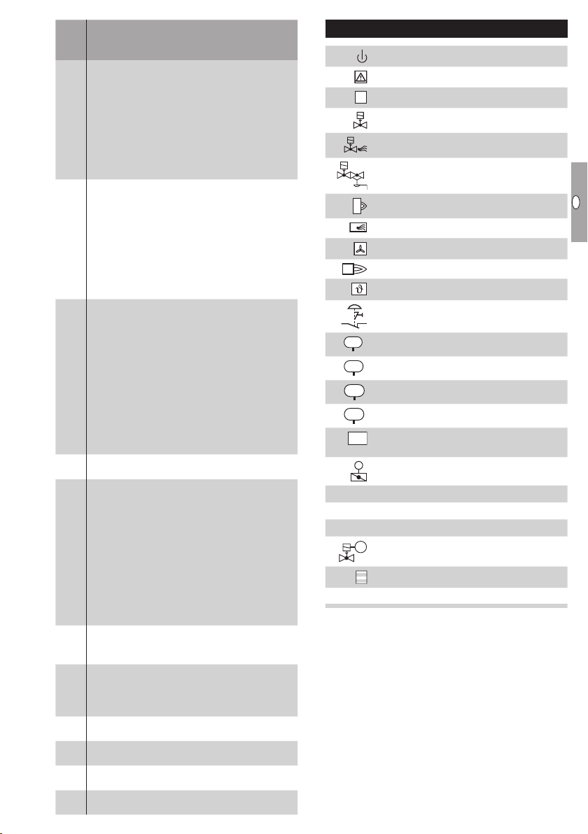
Legend
HT
Ready for operation
Safety interlocks (limits)
High temperature operation
Gas valve
(terminal47)
10 =
AND gating with purge pressure switch input
(terminal 48)
21 = Multi-flame control (MFC) start-up conditions
Function of terminal 68
0 = Off
8 = AND gating with emergency stop input
(terminal46)
9 = AND gating with air pressure switch input
73
(terminal47)
10 =
AND gating with purge pressure switch input
(terminal 48)
22 = Multi-flame control (MFC) operating conditions
Air valve
Air/gas ratio control valve
Burner
Purge
Controlled air flow
Burner operating signal
Start-up signal (BCU)
Capacity control (bus)
0 =
Off
1 =
MIN. to MAX. capacity; standby in position for
MIN. capacity
2 =
MIN. to MAX. capacity; standby in CLOSED
position
75
3 =
IGNITION to MAX. capacity; standby in
CLOSED position
4 =
MIN. to MAX. capacity; standby in position for
MIN. capacity; burner quick start
5 =
IGNITION to MAX. capacity; standby in
CLOSED position; burner quick start
Password
77
0000 – 9999
Burner application
0 = Burner 1
1 = Burner 1 with pilot gas
2 = Burner 1 and burner 2
3 = Burner 1 and burner 2 with pilot gas
4 = Two-stage burner 1
78
Emergency stop
Pressure switch for tightness control (TC)
Pressure switch for maximum pressure
Pressure switch for minimum pressure
Differential pressure switch
Input signal
depending on parameter xx
Control element with butterfly valve
Tightness control
TC
Half of the inlet pressure
pu/2
Outlet pressure
p
d
GZL
Valve with proof of closure switch
5 = Burner 1 and two-stage burner 2
= 1/0 in menox and 1/0 in flame mode
11
12 = 1/0 in menox and L/H/O in flame mode
13 = 1/0 in menox mode with 2 gas paths
Input/Output, safety circuit
I
Current consumption of sensor/contactor
N
14 = L/H/O in menox mode with 2 gas paths
Pilot burner
0 = With shut-down
79
1 = Continuous operation
Fieldbus communication
0 = Off
80
1 = With address check
2 = No address check
Safety time 1 t
94
2, 3, 5, 10 = Time in seconds
Flame proving period 1 t
95
0 – 20 = Time in seconds
Safety time 2 t
96
2, 3, 5, 10 = Time in seconds
Flame proving period 2 t
97
0 – 20 = Time in seconds
SA1
FS1
SA2
FS2
GB-25

GB
F
NL
I
E
Technical data
Electrical data
Mains voltage:
BCU..Q: 120 VAC, -15/+10%, 50/60 Hz, ±5%,
BCU..W: 230 VAC, -15/+10%, 50/60 Hz, ±5%,
for grounded mains.
Flame control:
with UV sensor or ionization sensor.
For intermittent or continuous operation.
Flame signal current:
ionization control: 1 – 25 μA,
UV control: 1 – 35 μA.
Ionization cable, UV cable:
max. 100m (328ft).
Contact rating:
Valve outputs V1, V2, V3 and V4 (terminals 13, 14, 15
and 57):
max. 1 A each, cos φ ≥ 0.6.
Actuator outputs (terminals 53, 54 and 55):
max. 1 A each, cos φ = 1.
Air valve output (terminal 10):
max. 1 A, cos φ = 1.
Ignition transformer (terminal 9):
max. 2 A.
Total current for the simultaneous activation of the
valve outputs (terminals 13, 14, 15, 57), of the
ignition transformer (terminal 9) and of the actuator
(terminals 53, 54, 55):
max. 2.5A.
Signalling contact for operating and fault signals:
max. 1 A (external fuse required).
Number of operating cycles:
The fail-safe outputs (valve outputs V1, V2, V3
andV4) are monitored for correct functioning and
are thus not subject to a max. number of operating
cycles.
Control actuator (terminals 53, 54 and 55):
max. 1,000,000,
signalling contact for operating signals:
max. 1,000,000,
signalling contact for fault signals:
max. 10,000,
On/Off button:
max. 10,000,
Reset/Information button:
max. 10,000.
Input voltage of signal inputs:
Rated value 120 V AC 230 V AC
Signal “1” 80 – 132 V 160 – 253 V
Signal “0” 0 – 20 V 0 – 40 V
Signal input current:
Signal “1” max. 5 mA
Fuses, replaceable, F1: T 3.15A H,
F2: T 2A H, pursuant to IEC 60127-2/5.
Mechanical data
Weight: 0.7 kg.
Dimensions (W × H × D): 102 × 115 × 112 mm.
Connections:
Screw terminals:
nominal cross-section 2.5mm²,
wire cross-section (rigid) min. 0.2mm²,
wire cross-section (rigid) max. 2.5mm²,
wire cross-section AWG min.24,
wire cross-section AWG max.12.
Spring force terminals:
nominal cross-section 2 x 1.5mm²,
wire cross-section min. 0.2mm²,
wire cross-section AWG min.24,
wire cross-section AWG max.16,
wire cross-section max. 1.5mm²,
rated current 10 A (8A UL), to be observed in
case of daisy chain.
Environment
Ambient temperature:
-20 to +60°C (-4 to +140°F),
no condensation permitted.
Storage temperature: -20 to +60°C (-4 to +140°F).
Enclosure: IP 20 pursuant to IEC529.
Installation location: min. IP 54 (for installation in a
control cabinet).
Designed lifetime
This information on the designed lifetime is based on
using the product in accordance with these operating
instructions. Once the designed lifetime has been
reached, safety-relevant products must be replaced.
Designed lifetime (based on date of manufacture)
in accordance with EN230 and EN298 forBCU:
20years.
You can find further explanations in the applicable
rules and regulations and on the afecor website
(www.afecor.org).
This procedure applies to heating systems. For
thermoprocessing equipment, observe local regulations.
GB-26

GB
F
NL
I
E
Logistics
Transport
Protect the unit from external forces (blows, shocks,
vibration). On receipt of the product, check that the
delivery is complete, see page2 (Part designations). Report any transport damage immediately.
Storage
Store the product in a dry and clean place.
Storage temperature: see page26 (Technical data).
Storage time: 6months before using for the first
time. If stored for longer than this, the overall service
life will be reduced by the corresponding amount of
extra storage time.
Packaging
The packaging material is to be disposed of in ac-
cordance with local regulations.
Disposal
Components are to be disposed of separately in
accordance with local regulations.
Accessories
▷ Spare parts, see www.partdetective.de
BCSoft
The current software can be downloaded from our
Internet site at http://www.docuthek.com. To do so,
you need to register in the DOCUTHEK.
Opto-adapter PCO 00
Including BCSoft CD-ROM,
Order No. 74960625.
Bluetooth adapter PCO 00
Including BCSoft CD-ROM,
Order No. 74960617.
Stickers for labelling
Connection plug set
For wiring the BCU.
74923998 74924000
Connection plugs with screw terminals for
FCU500/BCU 56x/580..K1,
Order No. 74923998.
Connection plugs with spring force terminals for
FCU500/BCU 56x/580..K2,
Order No. 74924000.
OCU
Operator-control unit for installation in the control
cabinet door. The program status or fault messages
can be read on the OCU. In Manual mode, the OCU
can be used to proceed through the sequence of
operating steps.
OK
OCU 500-1,
Switchable display: D, GB, F, NL, E, I,
Order No. 84327030,
OCU 500-2,
Switchable display: GB, DK, S, N, TR, P,
Order No. 84327031,
OCU 500-3,
Switchable display: GB, USA, E, P (BR), F,
Order No. 84327032,
OCU 500-4,
Switchable display: GB, RUS, PL, HR, RO, CZ,
Order No. 84327033.
BCU 570
Brenner 1
For printing with laser printers, plotters or engraving
machines, 27 × 18mm or 28 × 17.5mm.
Colour: silver.
GB-27

GB
F
NL
I
E
Certification
Declaration of conformity
We, the manufacturer, hereby declare that the products BCU560, BCU565 and BCU580 comply with
the essential requirements of the following Directives
and Standards.
Directives:
– 2014/30/EU
– 2014/35/EU
Regulation:
– (EU) 2016/426 – GAR
Standards:
– EN 298:2012
– EN 1643:2014
– EN 61508:2010, suitable for SIL3
The relevant product corresponds to the tested type
sample.
The production is subject to the surveillance proce-
dure pursuant to Regulation (EU) 2016/426 AnnexIII
paragraph3.
Elster GmbH
SIL, PL
For systems up to SIL 3 pursuant to EN 61508.
Pursuant to EN ISO 13849-1, Table 4, the BCU can
be used up to PL e.
FM approved
Factory Mutual (FM) Research Class:
7610 “Combustion Safeguards and Flame Sensing
Systems”
Suitable for applications pursuant to NFPA 86.
ANSI/CSA approved
Canadian Standards Association –
ANSI Z21.20 and CSA 22.2
Eurasian Customs Union
Scan of the Declaration of conformity (D,GB)– see
www.docuthek.com
Contact
Contact
If you have any technical questions, please contact
your local branch office/agent. The addresses are
available on the Internet or from ElsterGmbH.
We reserve the right to make technical modifications
in the interests of progress.
The products
BCU560, BCU 565 and BCU580
meet the technical specifications of the Eurasian
Customs Union.
Directive on the restriction of the use of
hazardous substances (RoHS) in China
Scan of the Disclosure Table China RoHS2 – see
certificates at www.docuthek.com
Strotheweg 1, D-49504 Lotte (Büren)
Tel. +49 541 1214-0
Fax +49 541 1214-370
hts.lotte@honeywell.com, www.kromschroeder.com
GB-28
Elster GmbH
 Loading...