

GB
F
NL
I
E
554
0
D GB F NL I E
TR CZ PL RUS H
DK S N P GR
➔ www.docuthek.com
Operating instructions
Gas pilots ZMI, ZMIC
© 2018 Elster GmbH · Edition 07.18
Translation from the German
Contents
Contents
Gas pilots ZMI, ZMIC ....................
Contents ..............................
Safety.................................
Checking the usage .....................
Checking the gas type...................
Installation ............................
ZMIC .................................4
ZMIC..K
...............................4
Wiring ................................4
Leak test ..............................4
Commissioning.........................5
ZMI...................................5
ZMIC .................................5
Maintenance
Replacing the electrode
ZMIC..K: replacing the bellows unit ..........6
ZMIC: replacing the ceramic tube............6
Accessories ...........................7
Technical data
Logistics
Declaration of Incorporation..............8
Certification
Contact ..............................0
...........................5
...................5
.........................7
..............................8
...........................9
Safety
Safety
Please read and keep in a safe place
Please read through these instructions
carefully before installing or operating. Following the
installation, pass the instructions on to the operator. This unit must be installed and commissioned
in accordance with the regulations and standards
in force. These instructions can also be found at
www.docuthek.com.
Explanation of symbols
• , , , ... = Action
▷ = Instruction
Liability
We will not be held liable for damage resulting from
non-observance of the instructions and non-compliant use.
Safety instructions
Information that is relevant for safety is indicated in
the instructions as follows:
DANGER
Indicates potentially fatal situations.
WARNING
Indicates possible danger to life and limb.
CAUTION
Indicates possible material damage.
All interventions may only be carried out by qualified
gas technicians. Electrical interventions may only be
carried out by qualified electricians.
Conversion, spare parts
All technical changes are prohibited. Only use OEM
spare parts.
Changes to edition 07.7
The following chapters have been changed:
– Checking the usage
– Wiring
– Maintenance
GB-1

GB
F
NL
I
E
Checking the usage
Intended use
Ionization-controlled gas pilot for safely igniting gas
burners. The capacity of the gas pilot should be 2
to 5% of that of the main burner.
Can also be used as independently operated burner.
For natural gas, coke oven gas, town gas and LPG.
Other types of gas on request.
This function is only guaranteed when used within
the specified limits – see also page7 (Technical
data). Any other use is considered as non-compliant.
ZMI
Type code
Code Description
ZMI Ionization pilot with forced air supply
6 – 5 Burner size
T T-product
B
G
D
For coke oven gas, town gas
50 – 000 Flame tube length
R Rp internal thread
N NPT internal thread
Part designations
and one electrode
For natural gas
For LPG
ZMIC
Type code
Code Description
ZMIC Ionization pilot with forced air supply,
one electrode and a ceramic flame
tube tip
8 Burner size
B
G
D
For coke oven gas, town gas
For natural gas
For LPG
00 – 000 Flame tube length
R Rp internal thread
K Bellows unit
Part designations
8
7
3
5
1
4
2
6
3
1
8
7
9
ZMIC
9
ZMIC..K
3
1
2
4
7
5
Burner housing
Interference-suppressed terminal boot with
protective cap
Air nozzle
4 Gas nozzle
5 Burner bracket
6 Flame tube
7 Enclosed documentation: operating
instructions and flow rate curves
Burner size, gas type, rated capacity P
tube length, connection– see type label.
D-49018 Osnabrück Germany
ZMI
Gas
Pmax.
max.
6
, flame
4
2
10
12
11
Burner housing
Interference-suppressed terminal boot with
protective cap
Air nozzle
4 Gas nozzle
5 Burner bracket with reducing nipple
6 Bellows unit with nut
7 Ceramic tube retaining piece
8 Ceramic tube clamping ring
9 Ceramic tube
0 Transport safety device (plastic tube and
O-ring)
Insulation strip
Enclosed documentation: operating instruc-
tions and flow rate curves
Burner size, gas type, rated capacity P
tube length, connection– see type label.
D-49018 Osnabrück Germany
ZMIC
Gas
Pmax.
max.
, flame
GB-2
GB
F
NL
I
E
Checking the gas type
2
1
2
1
Check if the gas nozzle diameter is suitable for
the required gas type.
Gas
type
ZMI 16 ZMI 25 ZMIC 28
B 0.94 (0.037) 1.40 (0.055) 1.40 (0.055)
G 0.76 (0.029) 1.05 (0.041) 1.05 (0.041)
D 1.30 (0.051) 1.78 (0.070) 1.78 (0.070)
▷ When changing the nozzle, remove the residue
of sealant from the burner housing.
▷ Suitable nozzles– see page7 (Accessories).
Nozzle
dia. [mm (inch)]
3
4
Position the
burner before
tightening the
cap screw.
5
Installation
DANGER
Risk of explosion! Ensure the connection is air-
tight.
CAUTION
Burner fault! If used as gas pilot, the gas and
air pressures must be higher than the connection
pressures of the main burner.
▷ Install the gas pilot so that reliable ignition of the
main burner is guaranteed.
▷ Attach the gas pilot securely.
▷
We recommend that a filter be installed in the
gas and air supply line respectively.
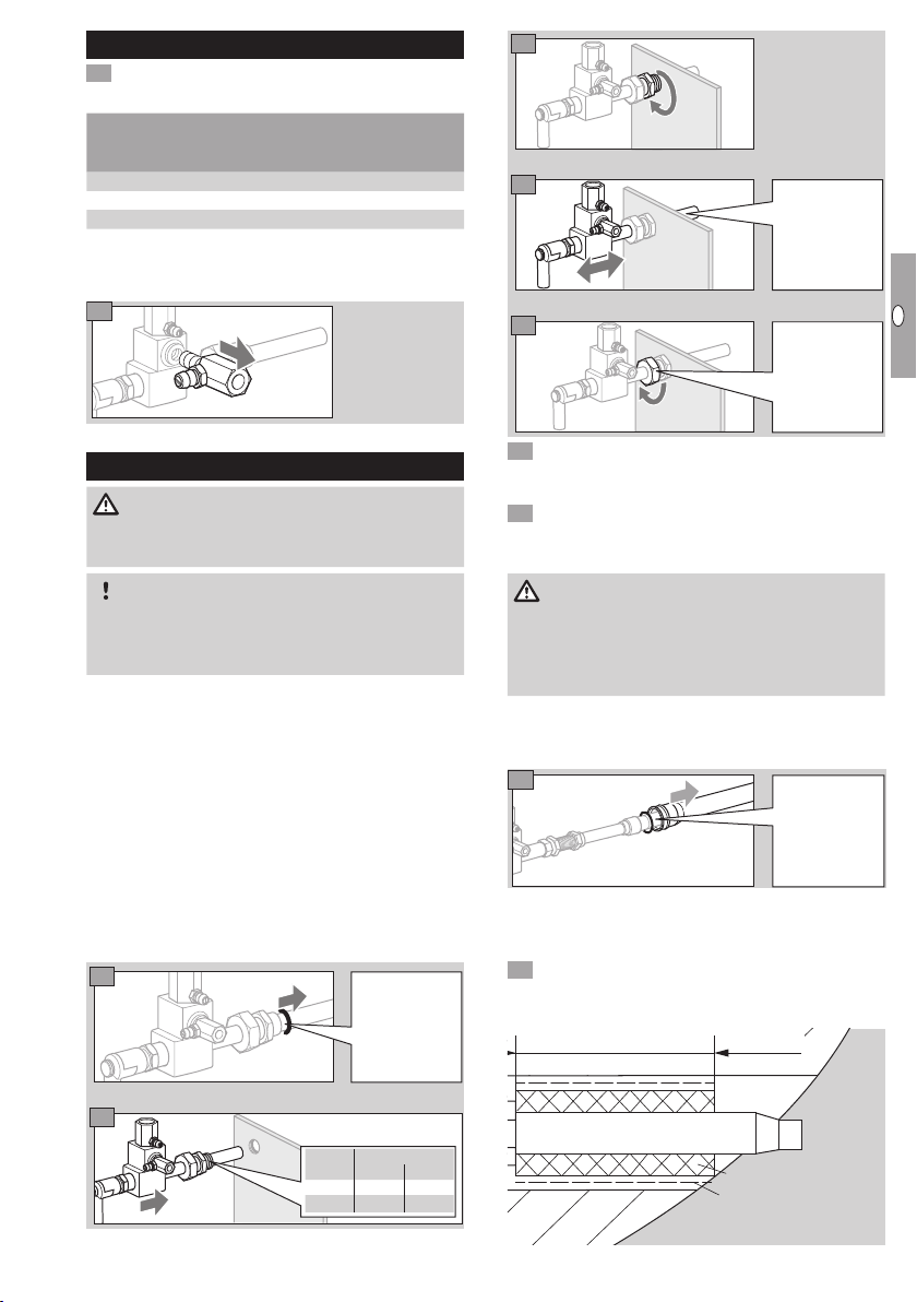
6 For air-tight installation, hand-tighten the union
nut then tighten it with a further turn (olive fitting
is secured).
7 Connect the pilot gas supply line with Rp¼ and
the air line with Rp½.
ZMIC
IMPORTANT
Only install the ZMIC when the burner block is cold.
When installing in a hot burner block, the fibre insulation can be damaged in such a way that the
burner can be thermally destroyed.
▷ Recommended inlet pressures:
gas: up to 100mbar (up to 40"WC),
air: up to 120mbar (up to 47"WC).
▷ Install pressure regulators and adjusting cocks
in the air and gas supply lines upstream of the
burner so that the air and gas pressures can
be adjusted.
To tighten the
union nut, use
a lubricant.
Remove
transport safety
device, masking tape and
O-ring.
ZMI
▷ Recommended inlet pressures:
gas: up to 80mbar (up to 32"WC),
air: up to 120mbar (up to 47"WC).
1
Remove the
transport
safety device.
Insulating the ceramic tube
▷ Protect the ceramic tube from thermal stress.
▷ Insulation with enclosed insulation strips.
Compress insulation strips by wrapping adhesive
foil around them tightly until they press tightly
against the ceramic tube.
5,5"
2
Burner
ZMI G½"
ZMI..T
Size
16
25
G1"
½" NPT 1" NPT
Insulation strip
Adhesive foil
GB-3

GB
F
NL
I
E
Check that the burner block hole is not blocked,
5
1 2 3
1
e.g. using a wooden stick.
ZMIC
4
6
Position the
burner before
tightening the
burner bracket.
7
8 Follow the reverse procedure when dismantling.
ZMIC..K
4
5
Wiring
DANGER
Electric shocks can be fatal! Before working on
possible live components, ensure the unit is disconnected from the power supply.
▷
For the ionization and ignition cables, use un-
screened high-voltage cable:
FZLSi 1/7 -50 to +180°C (-58 to +356°F),
Order No. 04250410,
or
FZLK 1/7 -5 to +80°C (23 to 176°F),
Order No. 04250409.
▷
Wire the burner as shown in the connection
diagrams of the automatic burner control unit/
ignition transformer.
▷ Flame control and ignition by a single electrode
(single-electrode operation).
4 Route the PE wire directly to the automatic burner
control unit.
Leak test
6
7
Position the
burner before
tightening the
bellows unit nut.
Secure the bel-
lows unit here
while tightening
the bellows unit
nut.
DANGER
Risk of explosion and poisoning! To ensure that
there is no danger resulting from a leak, check the
gas connections on the burner for leaks immediately
after the burner has been put into operation.
2
GB-4

GB
F
NL
I
E
Commissioning
76
7
DANGER
Risk of explosion! Please observe the appropriate
precautions when igniting the burners.
Risk of poisoning! Open the gas and air supply
so that the burner is always operated with excess
air– otherwise CO will form in the furnace chamber.
CO is odourless and poisonous! Conduct a flue
gas analysis.
▷ Arrange the adjustment and commissioning of
the burner with the system operator or manufacturer.
▷
Check the entire system, upstream devices and
electrical connections.
▷ Pre-purge the furnace chamber with air before
every ignition attempt.
DANGER
Risk of explosion! Fill the gas line to the burner
carefully and correctly with gas and vent it safely
into the open air – do not discharge the test volume
into the furnace chamber.
▷ If the burner does not ignite although the auto-
matic burner control unit has been switched on
and off several times: check the entire system.
▷ After ignition, monitor the gas and air pressures
measured on the burner and the flame. Measure
the ionization current. Switch-off threshold– see
automatic burner control unit operating instructions.
Switch on the system.
Open the manual valve.
Ignite the burner via the automatic burner control
unit.
4 Adjust the burner.
▷
Set the ionization current by adjusting the air
volume.
▷ The ionization current must be at least 5µA and
must not vary.
DANGER
Risk of explosion in case of CO being formed
in the furnace chamber! An incorrect change of
the burner settings may change the gas/air ratio
and lead to unsafe operating conditions. CO is
odourless and poisonous!
5 Set the pressure regulators for the gas and air
supply pressures to the maximum admissible
values, whereby the gas and air supply pressures
should be identical.
6
p
Gas
0
▷
Gas and air pressures: flow rate curves – see
p
Air
Adjust the burner
pressures for gas
and air on the
0
adjusting cocks
upstream of the
ZMI or ZMIC.
www.docuthek.com.
ZMI
▷ Inlet pressure:
gas: up to 80mbar (up to 32"WC),
air: up to 120mbar (up to 47"WC).
ZMIC
▷ Inlet pressure:
gas: up to 80mbar (up to 32"WC),
air: up to 120mbar (up to 47"WC).
Maintenance
▷ We recommend an annual function check.
DANGER
Electric shocks can be fatal! Before working
on possible live components, ensure the unit is
disconnected from the power supply.
Risk of burning! Dismantled burner components
can be hot due to outflowing flue gases.
Risk of explosion and poisoning in case of
burner adjustment with an air deficiency! Ad-
just the gas and air supply so that the burner is
always operated with excess air – otherwise CO
will form in the furnace chamber. CO is odourless
and poisonous! Conduct a flue gas analysis.
Check the ionization and ignition cables.
Measure the ionization current.
▷ The ionization current must be at least 5µA and
must not vary.
Disconnect the system from the electrical power
supply.
4 Shut off the gas and air supply– do not change
the restrictor settings.
5 Check the nozzles for dirt.
Replacing the electrode
ZMI 16
ZMIC 28
ZMI 25
GB-5

GB
F
NL
I
E
▷
1
2
1
Ensure that the electrode length does not change.
3
2
1
L
3
4
5
4
Spark plug
Dowel pin
Insulators
4 Burner head
5 Electrode tip
8 Remove dirt from electrode and insulators.
9 If the electrode tip or insulators are damaged,
replace the electrode.
▷
Before changing the electrode, measure the
total length L.
0 Connect the new electrode with the spark plug
using the dowel pin.
Adjust spark plug and electrode to the measured
total length L.
Screw the electrode into the burner housing.
Check distance L:
ZMI
L2
Burner L2
ZMI 16B 25 mm
ZMI 16D 21 mm
ZMI 16G 25 mm
ZMIC
Burner L2
ZMI 25B 35 mm
ZMI 25D 20 mm
ZMI 25G 35 mm
Burner L2
L2
ZMIC 28B
ZMIC 28G
• Reconnect the terminal boot.
• Produce a maintenance report.
ZMIC..K: replacing the bellows unit
Make a mark
to show the
length for reinstalling.
2
Secure the bel-
lows unit here
while unscrewing the bellows
unit nut.
50 mm
50 mm
5
6
7
Lubricate
thread with
ceramic
paste before
assembly.
8
Thread (R1)
must be facing
in the direction
of the furnace.
The bellows
unit gasket
cord must not
be twisted
when installing.
9
0 Insulate the ceramic tube and reinstall the burner,
see page3 (Installation).
ZMIC: replacing the ceramic tube
Remove the ZMIC – see page 6 (ZMIC..K:
replacing the bellows unit).
2
Spray screw
connection with
penetrating oil
and unscrew
clamping ring.
GB-6

GB
F
NL
I
E
3
2
Replace
ceramic tube
and copper
ring.
Ceramic paste
Apply ceramic paste to the screw connections after
4
50 mm
replacing any burner components in order to avoid
cold-setting.
Order number: 05012009.
Technical data
5
▷
Tighten the clamping ring with a torque of 30 Nm.
Lubricate retaining piece with
ceramic paste
before fitting
the clamping
ring.
6 Insulate the ceramic tube.
7 Reinstall the burner, see page3 (Installation).
Accessories
Gas nozzle
Burner Gas
type*
ZMI 6
ZMI 5
ZMIC 8
*
B = Natural gas
G = LPG
D = Coke oven gas, town gas
mm
(inch)
0.94
B
(0.037)
0.76
G
(0.029)
1.30
D
(0.051)
1.40
B
(0.055)
1.05
G
(0.041)
1.78
D
(0.070)
1.40
B
(0.055)
1.05
G
(0.041)
1.78
D
(0.070)
Order No.
ZMI/ZMIC ZMI..T
75455010 75442157
75455147 75448032
75455146 –
75455012 75443157
75455149 75448031
75455148 –
75455012 –
75455149 –
75455148 –
ZMI
Capacity:
ZMI 16: 1 to 2 kW (3.8 to 7.6 103 BTU/h),
ZMI 25: 2.5 to 4 kW (9.5 to 15.1 103 BTU/h)
(1.5 to 3.3kW in conjunction with coke oven gas,
town gas).
Capacities in kW refer to the lower calorific
valueHu and capacities in BTU/h refer to the upper
calorific valueHo.
Gas inlet pressure: 15 to 70 mbar (6 to 27"WC),
air inlet pressure: 15 to 90 mbar (6 to 35"WC),
each depending on the gas type
(burner pressures– seewww.docuthek.com,
Type of document: Flow rate curve).
Burner length increments: 100 mm (4").
Gas types: natural gas, LPG (gaseous) and coke
oven gas; other types of gas on request.
For cold air only.
Flame control: with flame rod.
Ignition: direct spark ignition (5kV ignition transformer).
Right-angle terminal boot: interference-suppressed.
Housing: aluminium.
Flame tube: heat-resistant steel.
Max. temperature at the tip of the flame tube:
<1000°C (< 1832°F),
< 900°C (< 1652°F) for lambda <1.
Storage temperature: -20°C to +40°C.
ZMIC
Capacity:
2.5 to 4.2 kW (9.5 to 15.9 10
3
BTU/h).
Capacities in kW refer to the lower calorific
valueHu and capacities in BTU/h refer to the upper
calorific valueHo.
Gas inlet pressure: up to 100mbar (up to 40"WC),
air inlet pressure: up to 120mbar (up to 47"WC),
each depending on the gas type
(burner pressures– see www.docuthek.com,
Type of document: Flow rate curve).
Burner length increments: 100 mm (4"),
"
length increments of the ZMIC28..K: 50 mm (2
).
Gas types: natural gas, LPG (gaseous) and coke
oven gas; other types of gas on request.
GB-7

GB
F
NL
I
E
For cold air only.
Matthias Rieken, Sebastian Escher
Konstrukteur / Designer
ist eine unvollständige Maschine nach Artikel 2g und ausschließlich zum Einbau in oder zum Zusammenbau mit einer anderen
is a partly completed machine pursuant to Article 2g and is designed exclusively for installation in or assembly with another
Folgende grundlegende Sicherheits- und Gesundheitsschutzanforderungen gemäß Anhang I dieser Richtlinie kommen zur
The following essential health and safety requirements in accordance with Annex I of this Directive are applicable and have
EN 746-2:2010 – Industrielle Thermoprozessanlagen; Sicherheitsanforderungen an Feuerungen und Brennstoffführungssysteme
06.07.2018
Die speziellen technischen Unterlagen gemäß Anhang VII B wurden erstellt und werden der zuständigen nationalen Behörde
The relevant technical documentation has been compiled in accordance with part B of Annex VII and will be sent to the
Die unvollständige Maschine darf erst dann in Betrieb genommen werden, wenn festgestellt wurde, dass die
The partly completed machine may only be commissioned once it has been established that the machine into which
– Industrial thermoprocessing equipment; Safety requirements for combustion and fuel handling systems
EN ISO 12100:2010 – Sicherheit von Maschinen – Allgemeine Gestaltungsleitsätze – Risikobeurteilung
und Risikominderung (ISO 12100:2010)
– Safety of machinery – General principles for design – Risk assessment
and risk reduction (ISO 12100:2010)
Diese Produkte entsprechen den Stoffbeschränkungen, die in RoHS II gelistet sind, fallen aber nicht in den
Anwendungsbereich der RoHS II (2011/65/EU).
These products comply with the substance restrictions of RoHS II, but they are not within the scope
of the Directive RoHS II (2011/65/EU).
Elster GmbH
Flame control: with flame rod.
Ignition: direct spark ignition (5kV ignition transformer).
Terminal boot: interference-suppressed.
Housing: aluminium.
Flame tube: ceramic flame tube.
Max. temperature at the tip of the flame tube:
1450°C (2642°F).
Storage temperature: -20°C to +40°C.
Logistics
Transport
Protect the unit from external forces (blows, shocks,
vibration). On receipt of the product, check that the
delivery is complete, see page2 (Part designations). Report any transport damage immediately.
Storage
Store the product in a dry and clean place.
Storage temperature: see page7 (Technical data).
Storage time: 2 years before using for the first time.
If stored for longer than this, the overall service life
will be reduced accordingly (by the corresponding
amount of extra storage time).
Packaging
The packaging material is to be disposed of in ac-
cordance with local regulations.
Disposal
Components are to be disposed of separately in
accordance with local regulations.
Declaration of Incorporation
pursuant to 2006/42/EC, Annex II, No. 1B
The products “Burners for gas ZMI and ZMIC” are
partly completed machines pursuant to Article2g and
are designed exclusively for installation in or assembly
with another machine or other equipment.
The following essential health and safety requirements
in accordance with Annex I of this Directive are ap-
plicable and have been fulfilled:
Annex I, Articles 1.1.3, 1.1.5, 1.3.2, 1.3.4, 1.5.2,
1.7.4, 1.5.10
The relevant technical documentation pursuant to
AnnexVIIB has been produced and will be transmitted to the competent national authorities in electronic
form on request.
The following (harmonized) standards have been
applied:
– EN 746-2:2010 – Industrial thermoprocessing
equipment – Safety requirements for combustion
and fuel handling systems
– EN ISO 12100:2010 – Safety of machinery– Gen-
eral principles for design – Risk assessment and
risk reduction (ISO 12100:2010)
These products comply with the substance restric-
tions of RoHS II, but they are not within the scope
of Directive RoHS II (2011/65/EU).
The partly completed machine may only be com-
missioned once it has been established that the
machine where the product mentioned above is to
be incorporated complies with the provisions of the
Machinery Directive 2006/42/EC.
Elster GmbH
Einbauerklärung / Declaration of Incorporation
nach 2006/42/EG, Anhang II, Nr. 1B / according to 2006/42/EC, Annex II No. 1B
Folgendes Produkt / The following product:
Bezeichnung: Zündbrenner für Gas
Description Pilot burner for gas
Typenbezeichnung / Type: ZAI, ZMI, ZMIC, ZKIH
Markenname / Branding:
Maschine oder Ausrüstung vorgesehen.
machine or other equipment.
Anwendung und wurden eingehalten:
been fulfilled:
Anhang I, Artikel / Annex I, Article
1.1.3, 1.1.5, 1.3.2, 1.3.4, 1.5.2, 1.7.4, 1.5.10
auf Verlangen in elektronischer Form übermittelt.
relevant national authorities on request as a digital file.
Folgende (harmonisierte) Normen wurden angewandt:
Maschine, in der das oben bezeichnete Produkt eingebaut werden soll, den Bestimmungen der Richtlinie für
Maschinen (2006/42/EG) entspricht.
the product mentioned above is to be incorporated complies with the provisions of the Machinery Directive
2006/42/EC.
Lotte (Büren)
Datum / Da te
Matthias Rieken, Sebastian Escher sind bevollmächtigt, die speziellen technischen Unterlagen gemäß Anhang VII B zusammenzustellen.
Matthias Rieken, Sebastian Escher are authorized to compile the relevant technical documentation according to Annex VII B.
/ The following (harmonized) standards have been applied:
GB-8
Postfach 28 09
D-49018 Osnabrück
Strotheweg 1
D-49504 Lotte (Büren)
Tel. +49 (0)541 12 14-0
Fax +49 (0)541 12 14-3 70
hts.lotte@honeywell.com
www.kromschroeder.com
GB
F
NL
I
E
Certification
Eurasian Customs Union
The product ZMI, ZMIC meets the technical specifi-
cations of the Eurasian Customs Union.
GB-9
 Loading...