

Page 1
03250523
F
NL
I
E
D GB F NL I E
TR CZ PL RUS H
DK S N P GR
➔ www.docuthek.com
Operating instructions
Burners for gas ZIC
© 2014 Elster GmbH · Edition 05.14
Contents
Translation from the German
Burners for gas ZIC . . . . . . . . . . . . . . . . . . . . .
Contents ..............................
Safety.................................
Checking the usage .....................
Installation ............................
Installing the ceramic tube . . . . . . . . . . . . . . . . . 3
Installation on the furnace .................4
Air connection, gas connection .............4
Installing the burner insert .................5
Wiring ................................5
Preparing commissioning ................6
Determining the flow rates . . . . . . . . . . . . . . . . . 6
Notes on the flow rate curve ............... 7
Restrictors .............................7
Hot-air compensation .................... 7
Commissioning.........................8
Igniting and adjusting the burner ............8
Tightness test...........................9
Cooling air .............................9
Blocking and recording the settings .........10
Maintenance ..........................0
Assistance in the event of malfunction ....
Accessories ..........................
Technical data ........................
Logistics .............................
Declaration of Incorporation.............4
Certification ..........................4
Contact ..............................4
Safety
Please read and keep in a safe place
Please read through these instructions
carefully before installing or operating. Following the
installation, pass the instructions on to the operator. This unit must be installed and commissioned
in accordance with the regulations and standards
in force. These instructions can also be found at
www.docuthek.com.
Explanation of symbols
• , , , ... = Action
▷ = Instruction
Liability
We will not be held liable for damage resulting from
non-observance of the instructions and non-compliant use.
Safety instructions
Information that is relevant for safety is indicated in
the instructions as follows:
DANGER
Indicates potentially fatal situations.
WARNING
Indicates possible danger to life and limb.
CAUTION
Indicates possible material damage.
All interventions may only be carried out by qualified
gas technicians. Electrical interventions may only be
carried out by qualified electricians.
Conversion, spare parts
All technical changes are prohibited. Only use OEM
spare parts.
Changes to edition .
The following chapters have been changed:
– Checking the usage
– Installation
– Preparing commissioning
– Commissioning
– Technical data
– Logistics
– Declaration of Incorporation
GB
GB-1
Page 2

F
NL
I
E
Checking the usage
Burner for heating industrial thermoprocessing equipment. The burner ZIC can be used in conjunction
with the ceramic tube set TSC in industrial furnaces
or firing systems with brick lining or ceramic fibre
lining. No burner quarl is necessary. For natural gas,
town gas and LPG. Other types of gas on request.
This function is only guaranteed when used within the
specified limits – see also page13 (Technical data). Any
other use is considered as non-compliant.
Burner
Construction stage, rated capacity Q
see type label.
GB
D-49018 Osnabrück Germany
ZIC 165HB-0/35-(18)D
BR 84246518
Qmax
BE 74970471 BK 18
Gas N SN
630 kW
Type code
Code Description
ZIC
Burner for gas with cast steel
ZICW
Burner for gas with cast steel
housing and internal insulation
65 – 00 Burner size
R
H
B
G
M
L
D
Butane, propane, propane/butane
Butane, propane, propane/butane
Low calorific value gas
Coke oven gas, town gas
L
R
Reduced max. connection rating
Length of burner extension [mm]:
-0
-00
-00…
/5/5-
Position of burner head [mm]
/5-…
-() to
Burner head identifier
-(99)
-(E) to
High temperature version
-(99E)
A – F Construction stage
, gas type–
max
D
17.11.
housing
Normal flame
Long, soft flame
Natural gas
Ignition lance
none
100
200
Part designations
4
2
3
5
1
9
6
7
8
Burner insert
Gas housing gasket
Air housing
4 Mounting flange
5 Mounting gasket
6 Type label
7 Burner extension (for ZIC..-100, ZIC..-200)
8 Clamping ring
9 Enclosed documentation (flow rate curves,
operating characteristic diagrams, dimension
sheet, spare parts list, spare parts drawing
and Declaration of Incorporation)
• Check letter marking and identification marks on
the burner head using the information provided
on the type label.
Ceramic tube
Length and diameter – see type label.
D-49018 Osnabrück Germany
TSC 165A154-300/35-Si-1500
RS MA Si-1500 SN
Type code
Code
TSC
65 – 00
A
54, 80
-00
/5Si-500
Position of burner head L9 [mm]
Tube length L8 [mm]
Ceramic tube material
Description
Ceramic tube set
Burner size
Cylindrical
Outlet dia. D4 [mm]
GB-2
Page 3
F
NL
I
E
L9
76
L8
5 Place the burner insert in such a way that the
insulators are protected against damage.
No burner extension
D4
Part designations
2
1
3
Burner tube gasket
Ceramic tube
Type label
Installation
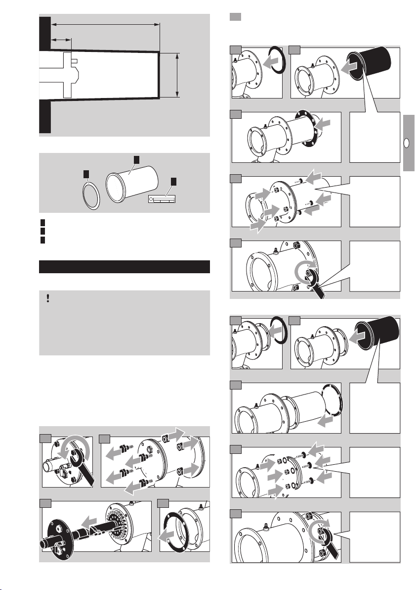
Installing the ceramic tube
CAUTION
Install the ceramic tube centrally and free of mechanical stress to avoid damage.
Remove and dispose of the transport safety device; to do this, remove the mounting flange or
clamping ring.
▷ Remove the burner insert in order to install the
ceramic tube. For this purpose, the air housing
can be placed in a vertical position on a smooth
working surface.
▷ On ZICW, avoid the formation of dust when dis-
mantling the burner insert and do not damage
the surface of the internal insulation.
1
2
8
9
10
With burner extension
76
8
9
Install the ceramic tube
centrally and
free of mecha nical stress.
Centre the
ceramic tube.
Tighten in
crosswise
fashion.
Install the ce ramic tube
cen trally and
free of mechanical stress.
Insert lock
washer pairs.
GB
3
4
10
Tighten in
crosswise
fashion.
GB-3
Page 4
F
NL
I
E
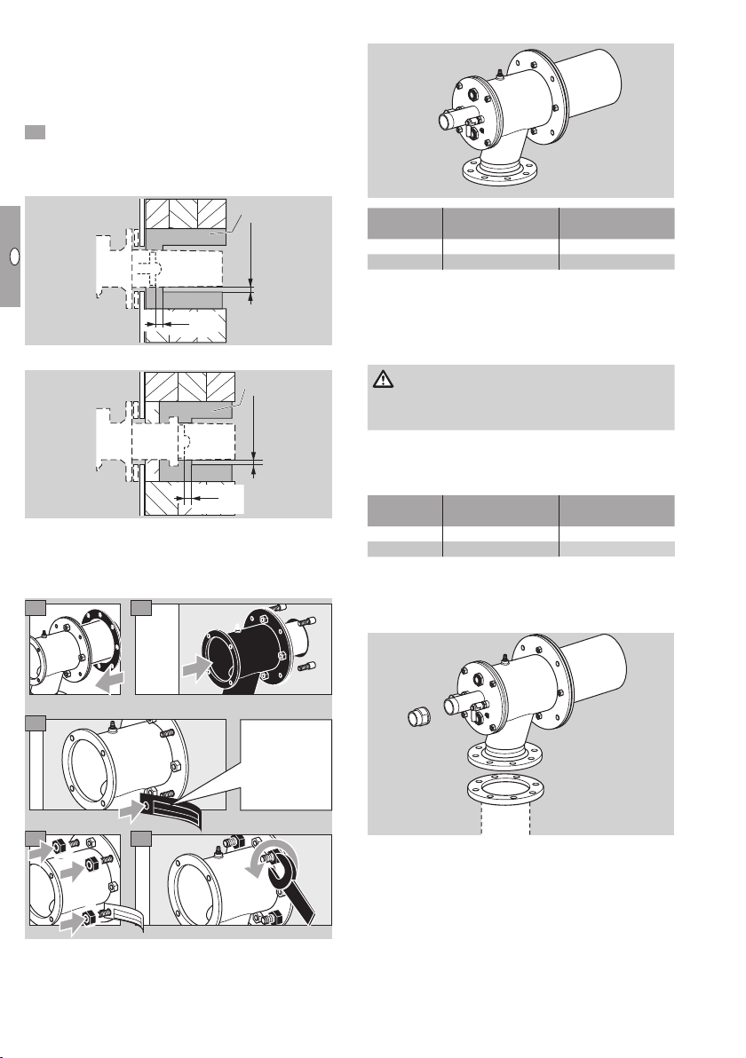
Insulating the ceramic tube
A/B
≥ 10 mm
≥ 0.4 in
20 mm
0.8 in
▷
Protect the burner extension from thermal stress.
▷
We recommend solid shaped parts A or high
temperature resistant ceramic fibrous material
B for insulation.
▷
Observe an annular gap of at least 10mm (0.4").
Insulate the ceramic tube at least as far as the
burner head, to a maximum of 20mm (0.8")
behind the burner head.
▷ Burner without extension:
A/B
GB
20 mm
0.8 in
≥ 10 mm
≥ 0.4 in
▷ Burner with extension:
A/B
≥ 10 mm
≥ 0.4 in
20 mm
0.8 in
Installation on the furnace
▷
When installing, always ensure that when the
burner is mounted, it is sealed tightly on the
furnace wall.
1
2
Air connection, gas connection
GA
LA
Type
ZIC 165 Rp 1½ DN 100
ZIC 200 Rp 2 DN 150
▷
Threaded connection to DIN 2999, flange dimen-
sions to DIN 2633, PN 16.
▷ Install flexible tubes or bellows units to prevent
mechanical stress or transmission of vibration.
▷ Ensure that the seals are undamaged.
DANGER
Risk of explosion! Ensure the connection is gastight.
Connection to ANSI/NPT
An adapter set is required for connection to ANSI/
▷
NPT, see page12 (Adapter set).
Type
ZIC 165 1½ – 11.5 NPT
ZIC 200 1½ – 11.5 NPT
* Flange hole diameter.
▷
Weld flange J to air pipe P for air connection
LA and use NPT thread adapter H for gas con-
nection GA.
Gas connection GAAir connection
LA
Gas connection GAAir connection
LA*
4.57"
6.72"
3
D
-
4
9
0
1
8
O
s
n
a
b
r
ü
c
k
G
e
r
m
a
n
y
T
S
C
6
5
A
O
4
8
-
3
0
0
/
3
5
-
S
S
i
1
i
-
1
5
5
0
0
4
5
0
0
Attach the
ceramic tube
type label.
▷ The nozzle set with NPT coupling is required for
GA
H
LA
J
P
integrated ignition lances, see page12 (Nozzle set).
GB-4
Page 5
F
NL
I
E
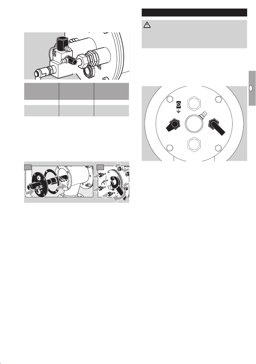
Ignition lance connections on the ZIO..L:
▷ Air connection la.
▷ Gas connection ga.
▷ Ignition lance capacity: 1.5kW.
la
ga
Type
gas connection
ga
ZIC..L Rp ¼ Rp ½
Ignition lance
ZIC..L with
adapter set
¼" NPT ½" NPT
Installing the burner insert
▷ The burner insert can be rotated to the required
position in increments of 90°.
▷
Insert the gas housing gasket between the
burner insert and the air housing.
On ZICW, avoid the formation of dust and do
▷
not damage the surface of the internal insulation.
1 2
▷ Tighten the burner insert in a crosswise fashion
with max. 37Nm (27.3lbfft).
Ignition lance
air connection
la
Wiring
DANGER
Electric shocks can be fatal! Before working on
possible live components, ensure the unit is disconnected from the power supply.
▷
For the ignition and ionization cables, use (un-
screened) high-voltage cable:
FZLSi 1/6 up to 180°C (356°F),
Order No. 04250410, or
FZLK 1/7 up to 80°C (176°F),
Order No. 04250409.
I
Ionization electrode I
▷
Install the ionization cable well away from mains
cables and interference from electro-magnetic
sources and avoid external electrical interference.
Max. length of ionization cable – see automatic
burner control unit operating instructions.
▷
Connect the ionization electrode to the automatic
burner control unit via the ionization cable.
Ignition electrode Z
▷
Length of ignition cable: max. 5 m (15 ft), recom-
mended < 1 m (40").
▷
For permanent ignition, max. ignition cable length
1 m (40").
Lay the ignition cable individually and not in a
▷
metal conduit.
▷
Install the ignition cable separately from ionization
and UV cables.
▷ A ≥ 7.5kV, ≥ 12mA ignition transformer is rec-
ommended; 5kV for ignition lance.
Z
GB
GB-5
Page 6

F
NL
I
E
Ionization and ignition electrodes
1
3
GB
6 Connect the PE wire for burner ground to the
4
2
5
burner insert. In the case of single-electrode operation, route the PE wire from the burner insert
directly to the terminal on the automatic burner
control unit.
WARNING
High-voltage risk! It is essential that a high-voltage
warning label is attached to the ignition cable.
7 For more detailed information on how to wire
the ionization and ignition cables, refer to the
operating instructions and connection diagrams
of the automatic burner control unit and ignition
transformer.
Preparing commissioning
Safety instructions
▷ Arrange the adjustment and commissioning of
the burner with the system operator or manufacturer.
▷
Check the entire system, upstream devices and
electrical connections.
▷
Note the operating instructions for individual
controls.
DANGER
The burner must only be commissioned by author-
ized trained personnel.
Risk of explosion! Please observe the appropriate
precautions when igniting the burner.
Risk of poisoning! Open the gas and air supply
so that the burner is always operated with excess
air – otherwise CO will form in the furnace chamber.
CO is odourless and poisonous! Conduct a flue
gas analysis.
▷
Pre-purge the furnace chamber with air (5 x
furnace chamber volume) before every ignition
attempt.
▷ If the burner does not ignite although the auto-
matic burner control unit has been switched on
and off several times: check the entire system.
▷
After ignition, monitor the flame and the gas and
air pressure measured on the burner. Measure
the ionization current. Switch-off threshold – see
automatic burner control unit operating instructions.
Z
+ µA –
I
▷
The burner must only be ignited at low fire
(between 10 and 30% of the rated capacity
Q
) – see type label).
max
DANGER
Risk of explosion! Fill the gas line to the burner
carefully and correctly with gas and vent it safely
into the open air – do not discharge the test volume
into the furnace chamber.
Determining the flow rates
Q
= PB/H
Gas
Q
Luft
▷ Q
: Gas flow rate in m3/h (ft3/h)
Gas
▷ PB: Burner capacity in kW (BTU/h)
▷ Hu: Gas calorific value in kWh/m3 (BTU/ft3)
▷ Q
: Air flow rate in m
Luft
▷ λ: Lambda, air index
▷
L
: Minimum air requirement in m
min
(SCF/SCF)
• Use the lower calorific value Hu.
▷ Information on the gas quality supplied can be
obtained from the competent gas supply company.
Common gas qualities
Gas type
Natural gas H
Natural gas L
Propane
Town gas
Butane
* Data in kWh/m
and data in BTU/SCF refer to the upper calorific
3
(n)
value Ho.
For safety reasons, a minimum air excess of 5%
▷
(lambda = 1.05) should be ensured.
u
= Q
. λ . L
Gas
min
3
/h (SCFH)
(n)
3
/m
(n)
H
u
3
kWh/m
(BTU/SCF)
11
(n)
L
min
3
3
m
/m
(n)
(SCF/SCF)
10.6
(n)
(1114)
8.9
8.6
(901)
25.9
24.4
(2568)
4.09
3.67
(425)
34.4
32.3
(3406)
refer to the lower calorific valueHu
3
(n)
GB-6
Page 7

F
NL
I
E
Notes on the flow rate curve
▷
If the gas density in the operating state differs
from that reflected in the flow rate curve, convert
the pressures according to the local operating
state.
pB = p
▷ δ
: Gas density reflected in the flow rate curve
M
[kg/m3 (lb/ft3)]
▷
δ
: Gas density in operating state [kg/m3 (lb/ft3)]
B
▷
pM: Gas pressure reflected in the flow rate curve
M
δ
M
δ
B
.
▷ pB: Gas pressure in operating state
• Read off the gas pressure p
p
from the enclosed flow rate curve for cold
air
air on the basis of the calculated flow rates.
[mbar ("WC)]
p
air
p
gas
and air pressure
gas
Hot-air compensation
▷
The combustion air pressure p
creased in hot-air operating mode (lambda =
must be in-
Air
constant).
250
[%]
200
Air
p
150
100
0 100 200 300 400
T
[°C]
Air
▷ The gas pressure is increased by 5–10mbar.
▷
The total burner capacity PB rises as the air tem-
perature T
[%]
B
120
P
increases.
Air
110
GB
p
gas
p
air
Q
gas
[m
Q
3
/h (ft3/h)]
air
▷ Note possible capacity changes due to positive
or negative pressures in the furnace/combustion
chamber. Add positive pressures or subtract
negative pressures.
▷ As not all the effects caused by the equipment
are known, setting the burner using the pressure
values is only approximate. It is possible to set
the burner precisely by measuring the flow rates
or flue gas.
Restrictors
▷ The air volume required for the low-fire rate at a
given air pressure is determined by the ignition
position of a butterfly valve, a bypass hole in the
air valve or an external bypass with restrictor.
100
0 100 200 300 400
T
[°C]
Air
Setting the air pressure for low fire and high
fire
Shut off the gas and air supply.
▷
Air measuring nipple L, external dia. = 9 mm (0.35").
2
Loosen
the screw
L
3
2turns.
4
Fully open
the air supply.
5
p
atm.
p
0
air
=
p
atm
atmospheric
pressure.
GB-7
Page 8

F
NL
I
E
Low fire:
▷ The burner must only be ignited at low fire (be-
tween 10 and 30% of the rated capacity Q
see type label).
max
• Reduce the air supply on the air control valve
and set the desired low-fire rate, e.g. using a
limit switch or mechanical stop.
On air control valves with bypass, the bypass
▷
orifice should be determined on the basis of the
required flow rate and the existing supply pressure if required.
High fire:
• Set the required air pressure p
tor upstream of the burner.
GB
on the air restric-
air
• When using air restricting orifices: check the air
pressure p
.
air
Preparing the gas pressure measurement for
low fire and high fire
• Connect all measuring devices for subsequent
fine adjustment of the burner.
▷ Leave the gas supply closed.
▷ Gas measuring nipple G, external dia. = 9 mm
(0.35").
• Read off the gas pressure p
flow rate from the enclosed flow rate curve for
for the required
gas
cold air.
[mbar ("WC)]
p
air
p
gas
1
Loosen the
p
gas
2
p
air
Q
gas
[m
Q
3
/h (ft3/h)]
air
G
screw 2 turns.
G
Integrated ignition lance on the ZIC..L:
▷ Air pressure test nipple l, external dia. = 9mm
–
(0.35").
▷
Gas pressure test nipple g, external dia. = 9mm
(0.35").
1
l
g
▷ Ignition lance:
p
= 30 – 50 mbar,
gas
p
= 30 – 50 mbar.
air
▷ Check flame stability and ionization current.
▷
The gas and air pressure of the ignition lance
must be higher than the gas and air pressure of
the main burner.
Commissioning
Igniting and adjusting the burner
WARNING
Ensure adequate ventilation of the furnace chamber
before each burner start!
▷ The burner housing will become hot during op-
eration with preheated combustion air. Provide
protection against accidental contact as required.
• All valves of the installation must be checked for
tightness before ignition.
Setting the low-fire rate:
• Set the valves to ignition position.
• Limit the maximum gas volume.
▷ Should an adjustable gas restrictor be installed
upstream of the burner, open the restrictor by
approx. a quarter.
• Open the gas supply.
• Ignite the burner.
▷ The safety time of the automatic burner control
unit starts to elapse.
• If no flame forms, check and adjust the gas and
air pressures of the start gas adjustment.
• In the case of operation with bypass (e.g. when
using an air/gas ratio control): check the bypass
nozzle and adjust if required.
• In the case of operation without bypass (e.g.
when using an air/gas ratio control without bypass):increase the low-fire rate setting.
• Check the basic setting or bypass of the air control valve.
GB-8
Loosen the
screws
2 turns.
2
l
g
Page 9

F
NL
I
E
• Check the position of the restrictor in the air line.
p
0
p
2
p
1
• Check the fan.
• Reset the automatic burner control unit and re-
ignite the burner.
▷ The burner ignites and proceeds to normal op-
eration.
• Check flame stability and ionization current at
low fire. Switch-off threshold – see automatic
burner control unit operating instructions.
Z
Tightness test
DANGER
To ensure that there is no danger resulting from a
leak, check the gas connections on the burner for
leaks immediately after the burner has been put
into operation.
1
+ μA –
I
• Monitor flame formation.
• Adjust the low-fire rate settings if required.
• If no flame forms – see page12 (Assistance in the
event of malfunction).
Setting the high-fire rate:
• Set the air and gas circuit of the burner to high
fire while continuously monitoring the flame.
▷
Avoid CO formation – always operate the burner
with excess air when starting up!
▷ When the desired maximum valve positions are
reached, set the gas pressure p
restrictor upstream of the burner.
p
atm.
p
gas
0
using the
gas
Re-adjusting the air flow rate:
• Check the air pressure p
adjust using the air restrictor if required.
on the burner and
air
• When using air restricting orifices: check the air
pressure p
and rework the orifice if required.
air
DANGER
Risk of explosion and poisoning during burner
adjustment with an air deficiency! Adjust the
gas and air supply so that the burner is always operated with excess air – otherwise CO will form in the
furnace chamber. CO is odourless and poisonous!
Conduct a flue gas analysis.
• Measure the gas and air flow rates if possible.
Determine the lambda value and re-adjust the
settings if required.
▷
Avoid condensation due to the furnace atmosphere entering the burner housing. While the
burner is switched off, at furnace temperatures
above 500°C (932°F), it must be cooled with a
low air volume – see page 9 (Cooling air).
Cooling air
▷ While the burner is switched off and depending
on the furnace temperature, there must be a certain air flow for cooling the burner components
6
5
4
Cooling air at 20°C
3
2
Air volume at rated capacity [%]
1
0
700 800 900 1000 1100 1200 1300 1400 1500
▷
Diagram: the relative air volume in percentage
Furnace temperature °C
ZIC
ZIC..KB..E
12
10
8
6
4
2
0
values, based on the air volume for the rated capacity of the relevant size, is given in the diagram.
For hot air (450°C), the values on the right-hand
axis are based on the standard air volume for
the relevant rated capacity.
▷ Leave the air fan switched on until the furnace
has cooled down completely.
GB
]
Cooling air at 450°C
Air volume at rated capacity [%
GB-9
Page 10

F
NL
I
E
Blocking and recording the settings
6 5
11 12
Produce a measurement report.
Set the burner to low fire and check the settings.
Set the burner to low and high fire several times
while monitoring the pressure settings, flue gas
values and flame patterns.
4 Remove the measuring devices and close off
the test nipples – tighten the grub screws.
5 Block and seal the adjusting elements.
6 Induce a flame failure, e.g. by pulling the plug off
the ionization electrode. The flame detector must
close the gas safety valve and signal a fault.
7 Switch the system on and off several times while
monitoring the automatic burner control unit.
GB
8 Produce an acceptance report.
DANGER
An incorrect change of the burner settings may
change the gas/air ratio and lead to unsafe operating conditions. Risk of explosion in case of CO
being formed in the furnace chamber! CO is odourless and poisonous!
Maintenance
We recommend that a function check is carried out
every six months.
WARNING
Risk of burning! Outflowing flue gases and burner
components are hot.
Check the ionization and ignition cables.
Measure the ionization current.
▷ The ionization current must be at least 5µA and
must not vary.
3
4
2
1
L
8 If the star 4 or insulator is damaged, replace
the electrode.
Before changing the electrode, measure the
▷
total length L.
9 Connect the new electrode with the spark plug
using the dowel pin .
0 Adjust spark plug and electrode to the measured
total length L.
▷
Turning the spark plug makes it easier to feed
the electrode into the burner insert.
Checking the burner
13
14
15
Z
+ μA –
I
Disconnect the system from the electrical power
supply.
4 Shut off the gas and air supply – do not change
the restrictor settings.
Checking the ignition and ionization
electrodes
▷
Ensure that the electrode length does not change.
7 Remove dirt from electrodes or insulators.
16
▷
If the burner insert is dismantled, the gas housing
gasket will have to be renewed.
7 Place the burner insert in a safe place.
Depending on the amount of dirt or wear: replace
▷
the ignition/ionization electrode rod and dowel
pin during servicing – see page10 (Checking the
ignition and ionization electrodes).
8 Check burner head for dirt and thermal cracks.
WARNING
Risk of injury! Burner heads have sharp edges.
GB-10
Page 11

F
NL
I
E
▷ When replacing any burner components: apply
21
ceramic paste to the screw connections in order
to avoid cold-setting – see page12 (Ceramic
paste).
9 Check the electrode positions.
▷ The insulator must be flush with the front edge
of the burner air disc.
▷
Distance of ignition electrode from ground pin or
gas nozzle: 2 ± 0.5 mm (0.08 ± 0.02").
)
mm
0.02"
0,5
2 ±
(0.08 ±
0 When the furnace chamber has cooled down,
check the ceramic tube through the furnace
flange.
New gas
housing
gasket.
27
8 Set the burner to low fire and compare the pres-
sure settings to those stated in the acceptance
report.
9 Set the burner to low and high fire several times
while monitoring the pressure settings, flue gas
values and flame patterns.
DANGER
Risk of explosion and poisoning during burner
adjustment with an air deficiency! Adjust the
gas and air supply so that the burner is always operated with excess air – otherwise CO will form in the
furnace chamber. CO is odourless and poisonous!
Conduct a flue gas analysis.
0 Produce a maintenance report.
GB
22
23
▷
Tighten the burner insert with max. 37 Nm
24
(27.3lbft).
5 Connect the system to the electrical power sup-
ply.
6 Open the gas and air supply.
GB-11
Page 12

F
NL
I
E
Assistance in the event of malfunction
DANGER
Electric shocks can be fatal! Before working on
possible live components, ensure the unit is disconnected from the power supply.
Risk of injury! Burner heads have sharp edges.
Fault-clearance must only be undertaken by authorized trained personnel.
▷ If no fault is detected when checking the burner,
proceed to the automatic burner control unit and
GB
check for faults in accordance with the relevant
operating instructions.
? Faults
! Cause
• Remedy
! Automatic burner control unit signals a fault.
• Check the ionization cable.
• Measure the ionization current by connecting a
micro-ammeter into the ionization cable: min.
5µA ionization current– stable signal.
Z
+ μA –
I
! Burner head dirty.
• Clean gas and air bore holes and air slots.
• Remove deposits on the burner head.
WARNING
Risk of injury! Burner heads have sharp edges.
? Burner does not function?
! Valves do not open.
• Check the voltage supply and wiring.
! Tightness control signals a fault.
• Check the valves for tightness.
• Note the tightness control operating instructions.
! Control valves do not move to low-fire position.
• Check the impulse lines.
! Gas inlet pressure is too low.
• Check the filter for dirt.
! Gas and air pressures on the burner are too low.
• Check the restrictors.
! Automatic burner control unit signals a fault.
• Check the ionization cables and ionization current.
• Check whether the burner is adequately
grounded.
• Note the automatic burner control unit operating
instructions.
? Burner performs a fault lock-out after burn-
ing faultlessly in normal operation?
! Incorrect gas and air flow rate settings.
• Check the gas and air pressures.
! No ignition spark is created.
• Check the ignition cable.
• Check the voltage supply and wiring.
• Check whether the burner is adequately
grounded.
• Check the electrodes – see page10 (Checking
the ignition and ionization electrodes).
! Excessive pressure fluctuations in the furnace
chamber.
• Ask Elster Kromschröder for control concepts.
Accessories
Ceramic paste
Apply ceramic paste to the relevant screw connections after replacing any burner components in order
to avoid cold-setting.
Order number: 05012009.
Adapter set
8×
For connecting ZIC to NPT/ANSI connections.
Burner Adapter set Order No.
ZIC 165
ZIC 200
Nozzle set
Available on request for connecting integrated
▷
ignition lances to NPT threads.
BR 165 NPT
BR 200 NPT
8×
74922636
74922637
GB-12
Page 13

F
NL
I
E
Technical data
Gas supply pressure: approx. 20 to 50 mbar,
air supply pressure: approx. 25 to 40 mbar,
each depending on flame shape, gas type and air
temperature (gas and air pressures – see operating
characteristic diagrams at www.docuthek.com).
Burner length increments: 100mm.
Gas types: natural gas, LPG (gaseous) and coke
oven gas; other gases on request.
Control type:
staged: On/Off, High/Low/Off,
continuous: constant λ value.
Most of the burner components are made of corrosion-resistant stainless steel.
Housing:
ZIC: St.
Flame control: with ionization electrode (UV sensor
as an option).
Ignition: direct spark ignition; ignition lance as an
option.
Maximum furnace temperature:
up to 1450°C (higher temperatures on request).
Maximum air temperature:
ZIC: 450°C,
ZICW: 500°C.
Storage temperature: -20°C to +40°C.
Burner Weight* [kg]
ZIC 165 23
ZIC 200 34.6
* Shortest overall length.
WARNING
applies to ZICW only
Information pursuant to REACH Regulation No.
1907/2006, Article 33. Insulation contains refrac-
tory ceramic fibres (RCF)/aluminium silicate wool
(ASW). RCF/ASW are listed in the Candidate List of
the European REACH Regulation No. 1907/2006.
Logistics
Transport
Protect the unit from external forces (blows, shocks,
vibration). On receipt of the product, check that the
delivery is complete, see page2 (Part designations). Report any transport damage immediately.
Storage
Store the product in a dry and clean place.
Storage temperature: see page13 (Technical data).
Storage time: 2 years before using for the first time.
If stored for longer than this, the overall service life
will be reduced accordingly (by the corresponding
amount of extra storage time).
Packaging
The packaging material is to be disposed of in ac-
cordance with local regulations.
Disposal
Components are to be disposed of separately in
accordance with local regulations.
GB
GB-13
Page 14

F
NL
I
E
Declaration of Incorporation
Sandra Runde
Die speziellen technischen Unterlagen gemäß Anhang VII B wurden erstellt und werden der zuständigen nationalen Behörde auf
according to 2006/42/EC, Annex II, No. 1B
The product ZIC is a partly completed machine pur-
suant to Article 2g and is designed exclusively for
installation in or assembly with another machine or
other equipment.
The following essential health and safety requirements
in accordance with Annex I of this Directive are applicable and have been fulfilled:
Annex I, Articles 1.1.3, 1.1.5, 1.3.2, 1.3.4, 1.5.2, 1.7.4
The relevant technical documentation has been com-
piled in accordance with part B of Annex VII and will
be sent to the relevant national authorities on request
GB
as a digital file.
The following (harmonized) standards have been
applied:
– EN 746-2 (2010) – Industrial thermoprocessing
equipment; Safety requirements for combustion
and fuel handling systems
– EN ISO 12100 (2010) – Safety of machinery –
General principles for design – Risk assessment
and risk reduction (ISO 12100:2010)
The partly completed machine may only be commis-
sioned once it has been established that the machine
into which the product mentioned above is to be
incorporated complies with the provisions of the
Machinery Directive 2006/42/EC.
Elster GmbH
Einbauerklärung / Declaration of Incorporation
nach 2006/42/EG, Anhang II, Nr. 1B / according to 2006/42/EC, Annex II No. 1B
Folgendes Produkt / The following product:
Bezeichnung: Brenner für Gas
Description Burner for gas
Typenbezeichnung / Type: BIO, BIOA, ZIO, BIC, BICA, ZIC
ist eine unvollständige Maschine nach Artikel 2g und ausschließlich zum Einbau in oder zum Zusammenbau mit einer anderen
Maschine oder Ausrüstung vorgesehen.
is a partly completed machine pursuant to Article 2g and is designed exclusively for installation in or assembly with another
machine or other equipment.
Folgende grundlegende Sicherheits- und Gesundheitsschutzanforderungen gemäß Anhang I dieser Richtlinie kommen zur
Anwendung und wurden eingehalten:
The following essential health and safety requirements in accordance with Annex I of this Directive are applicable and have
been fulfilled:
Anhang I, Artikel / Annex I, Article
1.1.3, 1.1.5, 1.3.2, 1.3.4, 1.5.2, 1.7.4
Verlangen in elektronischer Form übermittelt.
The relevant technical documentation has been compiled in accordance with part B of Annex VII and will be sent to the relevant
national authorities on request as a digital file.
Folgende (harmonisierte) Normen wurden angewandt: / The following (harmonized) standards have been applied:
EN 746-2:2010 – Industrielle Thermoprozessanlagen; Sicherheitsanforderungen an Feuerungen und Brennstoffführungssysteme
– Industrial thermoprocessing equipment; Safety requirements for combustion and fuel handling systems
EN ISO 12100:2010 – Sicherheit von Maschinen – Allgemeine Gestaltungsleitsätze – Risikobeurteilung
und Risikominderung (ISO 12100:2010)
– Safety of machinery – General principles for design – Risk assessment
and risk reduction (ISO 12100:2010)
Die unvollständige Maschine darf erst dann in Betrieb genommen werden, wenn festgestellt wurde, dass die Maschine,
in der das oben bezeichnete Produkt eingebaut werden soll, den Bestimmungen der Richtlinie für Maschinen
(2006/42/EG) entspricht.
The partly completed machine may only be commissioned once it has been established that the machine into which
the product mentioned above should be incorporated complies with the provisions of the Machinery Directive
2006/42/EC.
Lotte (Büren)
24.03.2014
Datum / Date
Sandra Runde ist bevollmächtigt, die speziellen technischen Unterlagen gemäß Anhang VII B zusammenzustellen.
Sandra Runde is authorized to compile the relevant technical documentation according to Annex VII B.
BIOW, ZIOW, BICW, ZICW
Konstrukteurin / Designer
Certification
Approval for Russia
Elster GmbH
Postfach 28 09
D-49018 Osnabrück
Strotheweg 1
D-49504 Lotte (Büren)
Tel. +49 (0)541 12 14-0
Fax +49 (0)541 12 14-3 70
info@kromschroeder.com
www.kromschroeder.com
Certified by Gosstandart under Technical Regulations.
Approved by Rostekhnadzor (RTN).
Contact
If you have any technical questions, please contact
your local branch office/agent. The addresses are
available on the Internet or from ElsterGmbH.
We reserve the right to make technical modifications
in the interests of progress. info@kromschroeder.com, www.kromschroeder.com
Elster GmbH
Postfach 28 09, D-49018 Osnabrück
Strotheweg 1, D-49504 Lotte (Büren)
T +49 541 1214-0
F +49 541 1214-370
GB-14
 Loading...