

03250560
F
NL
I
E
Edition 12.11
D GB F NL I E
TR CZ PL RUS H
DK S N P GR
➔ www.docuthek.com
Operating instructions
Ionization pilot burners
ZAI, ZMI, ZKIH
Translation from the German
© 2011 Elster GmbH
Contents
Checking the usage . . . . . . . . . . . . . . . . . . . . . 2
Setting the gas type . . . . . . . . . . . . . . . . . . . . . 3
Installation . . . . . . . . . . . . . . . . . . . . . . . . . . . . 4
Wiring . . . . . . . . . . . . . . . . . . . . . . . . . . . . . . . . 5
Tightness test. . . . . . . . . . . . . . . . . . . . . . . . . . 6
Commissioning. . . . . . . . . . . . . . . . . . . . . . . . . 7
Maintenance. . . . . . . . . . . . . . . . . . . . . . . . . . . 8
Replacing the electrodes . . . . . . . . . . . . . . . . . . 8
Accessories . . . . . . . . . . . . . . . . . . . . . . . . . . 10
Technical data. . . . . . . . . . . . . . . . . . . . . . . . . 11
Declaration of Incorporation. . . . . . . . . . . . . 12
Safety
Please read and keep in a safe place
Please read through these instructions
carefully before installing or operating. Following the
installation, pass the instructions on to the operator. This unit must be installed and commissioned
in accordance with the regulations in force. These
instructions can also be found at www.docuthek.com.
Explanation of symbols
• , 1 , 2 , 3 ... = Action
= Instruction
Liability
We will not be held liable for damages resulting
from non-observance of the instructions and noncompliant use.
Safety instructions
Information that is relevant for safety is indicated in
the instructions as follows:
DANGER
Indicates potentially fatal situations.
WARNING
Indicates possible danger to life and limb.
CAUTION
Indicates possible material damage.
All interventions may only be carried out by qualified
gas technicians. Electrical interventions may only be
carried out by qualified electricians.
Conversion, spare parts
All technical changes are prohibited. Only use OEM
spare parts.
Transport
On receipt of the product, check that the delivery is
complete (see Part designations). Report any transport damage immediately.
Storage
Store the product in a dry place. Ambient temperature: see Technical data.
GB
GB-1
F
NL
I
E
Checking the usage
Intended use
Ionization-controlled pilot burners for safely igniting
gas burners. The capacity of the pilot burner should
be 2 to 5% of that of the main burner.
Can also be used as independently operated burners.
For natural gas, town gas, coke oven gas and LPG.
Other types of gas on request.
This function is only guaranteed when used within the
specified limits – see also page11 (Technical data). Any
other use is considered as non-compliant.
ZMI
Type code
ZMI
Ionization pilot burner with forced air
supply and one electrode
16 – 25 Burner size
T T-product
B
D
G
For natural gas
For town gas, coke oven gas
For LPG
150 – 1000 Flame tube length
R Rp internal thread
N NPT internal thread
ZAI
GB
Type code
ZAI
Thermo ionization pilot burner with two
electrodes
K Double-cone olive for 8mm tube
TN 1/4" NPT internal thread
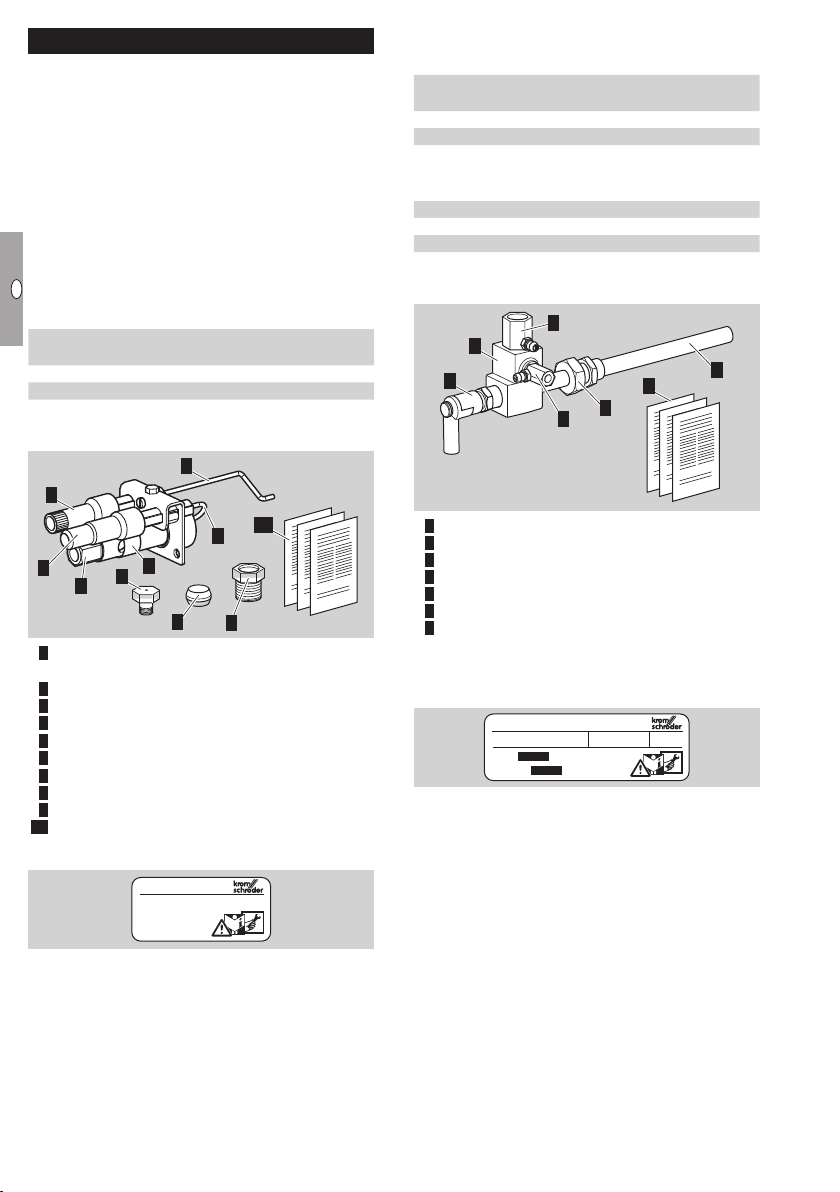
Part designations
3
2
10
4
1
6
5
7
8
9
1 Interference-suppressed adapter for ignition
electrode
2 Adapter for ionization electrode
3 Ionization electrode
4 Ignition electrode
5 Air slide valve
6 Gas connection
7 0.7 mm gas nozzle for LPG
8 Cone olive (only for ZAI K)
9 Cap screw (only for ZAI K)
10
Enclosed documentation: operating instructions
Gas connection– see type label.
D-Osnabrück
Germany
ZAI K
Part designations
3
1
2
4
7
5
1 Burner housing
2 Interference-suppressed electrode adapter
3 Air nozzle
4 Gas nozzle
5 Mounting device
6 Flame tube
7 Enclosed documentation: operating
instructions and flow rate curves
Burner size, gas type, rated capacity P
tube length, connection– see type label.
D-49018 Osnabrück Germany
ZMI
Gas
Pmax.
max.
6
, flame
GB-2
F
NL
I
E
ZKIH
2 3
1
0.7
2
2 3
1
Gasdüse ∅ 0,7 mm (0,028") für
Flüssiggas.
Gasdüse für Stadtgas ∅ 1,8 mm
(0,07") separat bestellen
(Best.-Nr. 74472880).
Gas nozzle Ø 0.7 mm (0.028")
for LPG.
Order gas nozzle for town gas Ø
1.8 mm (0.07") separately
(Order No. 74472880).
Type code
ZKIH Ionization pilot burner with forced air
supply
150 – 1000
Burner tube length
/100 Flame tube length
R Rp internal thread
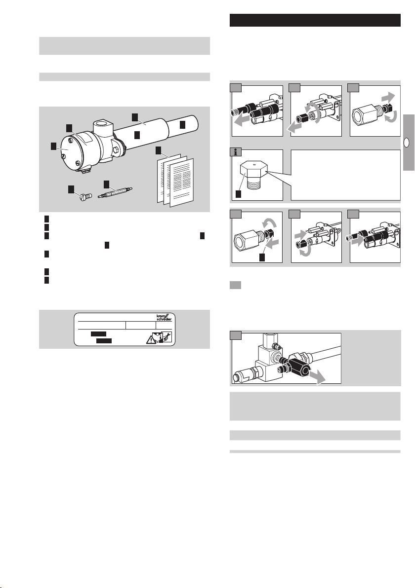
Part designations
Setting the gas type
ZAI
Pilot burners ZAI are set for natural gas on de-
livery.
If the pilot burner is to be used with a different
type of gas, retrofit the burner for its use.
1
2
4
1 Burner housing
3
a
5
b
6
0.7
Gas nozzle Ø 0.7 mm (0.028")
for LPG.
GB
Order gas nozzle for town gas Ø
2
4
1.8 mm (0.07") separately
(Order No. 74472880).
5
6
2 Burner housing cover
3 Burner tube set, comprising protective tubea
and flame tubeb
4 Retaining screw for nozzle insert (in burner
housing)
5 Nozzle insert (in burner housing)
6 Enclosed documentation: operating
instructions and flow rate curves
Rated capacity P
D-49018 Osnabrück Germany
ZKIH
Gas
Pmax.
, gas type– see type label.
max.
ZMI
1 Check if the nozzle diameter is suitable for the
2
required gas type.
When changing the nozzle, remove the residue
of sealant from the burner housing.
Suitable nozzles– see page10 (Accessories).
1
Nozzle dia.
Gas type
[mm (inch)]
ZMI 16 ZMI 25
B 0.94 (0.037) 1.40 (0.055)
G 0.76 (0.029) 1.05 (0.041)
D 1.30 (0.051) 1.78 (0.070)
ZKIH
Pilot burners ZKIH are set for natural gas on
delivery.
If the pilot burner is to be used with a different
type of gas, retrofit the burner for its use.
GB-3
F
NL
I
E
1
1
2
I
Z
3
1
burner using the
Installation
DANGER
Risk of explosion! Ensure the connection is gas-
tight.
Install the pilot burner so that reliable ignition of
2
GB
I
3
Z
4
=
+
+
Natural gas
=
LPG
=
Town gas
5
6
the main burner is guaranteed.
Attach the pilot burner securely.
We recommend that a filter be installed in the
gas and air supply line respectively.
ZAI
Inlet pressure:
natural gas: max. 35 mbar (14"WC),
town gas: max. 30 mbar (12"WC),
LPG: max. 60 mbar (23 "WC).
In the case of higher inlet pressures, insert a gas
restrictor orifice.
Ensure air intake is not obstructed.
The ZAI has bare electrodes and no protective
flame tube. Protective tube, see page10 (Accessories).
WARNING
Risk of injury! Observe the projecting ionization
electrode.
Attach the
two holes on
the fastening
lug.
7
For operation with town gas, screw the retaining
8
screw back in without the nozzle insert– do not
store the nozzle insert in the connection box:
danger of short-circuits.
9 After conversion to another type of gas, adjust
the air volume– see page7 (Commissioning).
8
≈ 2 mm
9
When tightening the cap screw 9, ensure that
the cone olive 8 is correctly positioned– lubricate
the cone olive.
ZAI flow rate curve– see www.docuthek.com
ZMI
Recommended inlet pressures:
gas: 50 – 60 mbar (19.7 – 23.6 "WC),
air: 50 – 60 mbar (19.7 – 23.6 "WC).
Install pressure regulators and adjusting cocks
in the air and gas supply lines upstream of the
burner so that the air and gas pressures can
be adjusted.
CAUTION
Burner fault! If used as pilot burner, the gas and
air pressures must be higher that the connection
pressures of the main burner.
GB-4
2
Connect the
pilot gas line
with 8 mm
tube.

F
NL
I
E
1
5
4
1
3
2
1
Remove the
transport safety
device.
2
2
Burner
ZMI G½"
ZMI..T
Size
16
25
G1"
½" NPT 1" NPT
3
3
4 Connect the pilot gas line with Rp¼ and the air
line with Rp½.
GB
For connecting pilot gas and air lines with NPT
thread, order the adapter set– see page10 (Accessories).
4
Position the
burner before
tightening the
cap screw.
Wiring
DANGER
Electric shocks can be fatal! Before working on
possible live components, ensure the unit is disconnected from the power supply.
To tighten the
union nut, use
a lubricant.
For the ionization and ignition cables, use
unscreened high-voltage cable:
FZLSi 1/7 -50 to 180°C
(-58 to 356°F),
Order No. 04250410,
or
FZLK 1/7 -5 to 80°C
6 Hand tighten the union nut, mark a position for
gas-tight installation and then tighten with a further turn (360°).
7 Connect the pilot gas line with Rp¼ and the air
line with Rp½.
ZKIH
Inlet pressure:
Gas
[mbar ("WC)]
Natural gas 20 (8)
Town gas 17 (6.8)
LPG 30 (12)
Flow rate curves– see www.docuthek.com
In the case of higher gas pressures, insert a
gas restrictor orifice– see page10 (Accessories).
(23 to 176°F),
Order No. 04250409.
Wire the burner as shown in the connection
diagrams of the automatic burner control unit/
ignition transformer.
ZAI
1
I = Ionization
I
electrode
Z
Z = Ignition
electrode
2
3
Screw for
PEwire
1
4 Connect the PE wire for burner ground to the
fastening lug on the burner insert.
GB-5

F
NL
I
E
ZMI
2 31
2 31
4
1
Flame control with single-electrode operation.
1 2 3
4 Route the PE wire directly to the automatic burner
control unit.
ZKIH
GB
Tightness test
DANGER
Risk of explosion and poisoning! To ensure that
there is no danger resulting from a leak, check the
gas connections on the burner for leaks immediately
after the burner has been put into operation.
ZAI
1
2
4
5
I
Tighten the PGcable gland.
I = Ionization electrode
Z = Ignition electrode
Z
= Screw for PEwire
6 Tighten ionization and ignition cables securely.
WARNING
Electric shocks can be fatal! Live components
in the housing connection chamber.
7 Replace seal and cover and screw into place.
8 Connect the PE wire for burner ground to the
burner.
ZMI
2
ZKIH
1
2
GB-6

F
NL
I
E
Commissioning
5
6
5
6
5 6
DANGER
Risk of explosion! Please observe the appropriate
precautions when igniting the burners.
Risk of poisoning! Open the gas and air supply
so that the burner is always operated with excess
air – otherwise CO will form in the furnace chamber.
CO is odourless and poisonous! Conduct a flue
gas analysis.
ZKIH: electric shocks can be fatal! The burner
housing cover must be fitted before igniting the
burner.
Arrange the adjustment and commissioning of
the burner with the system operator or manufacturer.
Check the entire system, upstream devices and
electrical connections.
Pre-purge the furnace chamber with air (5 x
furnace chamber volume) before every ignition
attempt.
Fill the gas line to the burner carefully and correctly with gas and vent it safely into the open
air – do not discharge the test volume into the
furnace chamber. Risk of explosion!
If the burner does not ignite although the auto-
matic burner control unit has been switched on
and off several times: check the entire system.
After ignition, monitor the gas and air pressures
measured on the burner and the flame. Measure
the ionization current. Switch-off threshold– see
automatic burner control unit operating instructions.
1 Switch on the system.
2 Open the manual valve.
3 Ignite the burner via the automatic burner control
unit.
4 Adjust the burner.
Set the ionization current by adjusting the air
volume.
DANGER
Risk of explosion in case of CO being formed
in the furnace chamber! An incorrect change of
the burner settings may change the gas/air ratio
and lead to unsafe operating conditions. CO is
odourless and poisonous!
ZAI
The air slide is open on deliv-
ery. Only close the air slide if
the burner flame is not stable.
ZMI
5 Set the pressure regulators for the gas and air
supply pressures to the maximum admissible
values, whereby the gas and air supply pressures
should be identical.
0
Adjust the burner pressures for
gas and air on
the adjusting
cocks upstream
of the ZMI.
p
Gas
0
The air inlet pressure must always be higher than
p
Air
the gas inlet pressure: operating characteristic
diagrams– see www.docuthek.com.
Inlet pressure:
gas: 20 – 50 mbar (8 – 20"WC),
air: 20 – 50 mbar (8 – 20 "WC).
ZKIH
Inlet pressure for air adjustment screw set at
the factory:
Gas
[mbar ("WC)]
Air
[mbar ("WC)]
Natural gas 20 (8) 20 (8)
Town gas 17 (6.8) 35 (13.8)
LPG 30 (12) 30 (12)
If the air inlet pressure cannot be set to the rec-
ommended value owing to the factory setting of
the air adjustment screw, readjust the air adjustment screw.
7
Turn the air adjustment screw
to the left to increase the air
I
Z
flow. Turn the air adjustment
screw to the right to reduce
the air flow.
8 Replace seal and cover and screw into place.
GB
GB-7

F
NL
I
E
Maintenance
7
6
7
8
6
76
7
We recommend an annual function check.
DANGER
Electric shocks can be fatal! Before working
on possible live components, ensure the unit is
disconnected from the power supply.
Risk of burning! Dismantled burner components
can be hot due to outflowing flue gases.
Risk of explosion and poisoning during burner
adjustment with an air deficiency! Adjust the
gas and air supply so that the burner is always operated with excess air – otherwise CO will form in the
GB
furnace chamber. CO is odourless and poisonous!
Conduct a flue gas analysis.
1 Check the ionization and ignition cables.
2 Measure the ionization current.
The ionization current must be at least 5µA and
must not vary.
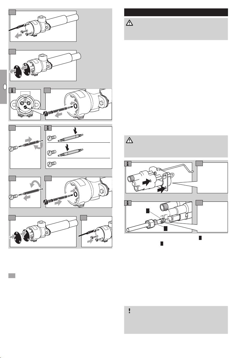
9
For correct positioning, slide
in the electrodes until the
projection of the retaining plate
engages into the groove.
When sliding in the
electrodes,
ensure they
are aligned.
10 Once the electrodes have been positioned, hand
tighten the retaining plate screw using a spanner
(approx. 3turns).
After tightening, the electrodes cannot be moved
any more.
ZMI
Z
+ μA –
I
3 Disconnect the system from the electrical power
supply.
4 Shut off the gas and air supply – do not change
the restrictor settings.
5 Check the nozzles for dirt.
Replacing the electrodes
ZAI
8
Loosen the
screw of the
retaining plate
by turning
it approx.
3turns.
Groove for
correct positioning of the
electrode.
ZMI 16
Ensure that the electrode length does not change.
2
1
ZMI 25
3
L
5
4
1 Spark plug
2 Dowel pin
3 Insulators
4 Burner head
4 Electrode tip
8 Remove dirt from electrodes and insulators.
9 If the electrode tip or insulators are damaged,
replace the electrode.
Before changing the electrode, measure the
total length L.
10 Connect the new electrode with the spark plug
using the dowel pin.
11 Adjust spark plug and electrode to the measured
total length L.
12 Screw the electrode into the burner housing.
13 Check distance L2:
GB-8

F
NL
I
E
10
22 mm
2 mm
14
12
13
1
2
1
2
Burner L2
ZMI 16B 25 mm
ZMI 16D 21 mm
ZMI 16G 25 mm
L1
Burner L2
ZMI 25B 35 mm
ZMI 25D 20 mm
ZMI 25G 35 mm
L2
12
13
1
22 mm
Align the ignition electrode1
2
and the ionization electrode2.
Adjust the spacing of the
electrode tips.
2
ZKIH
6 Undo the housing cover screws, remove seal
and housing cover.
7 Unscrew the ionization and ignition cables.
14
2 mm
1
Slide the rear guide lug as far
GB
as it will go in the direction
WARNING
High-voltage risk! Live components in the housing
of the burner housing. Hand
tighten the screw.
connection chamber.
8 Unscrew the PE wire for burner ground from the
burner.
9 Remove the burner– see page4 (Installation).
15
Align the insulators.
Removal and reassembly of the electrodes is fa-
cilitated, when the housing is placed in a vertical
position on a smooth working surface.
6 mm
Loosen the
screws ½a
turn.
16
Slide the front guide lugs as far
as they will go in the direction of the burner head. Hand
11
2
2
1
1
Replace the
electrodes
one after the
other.
17
tighten the screw.
For longer burners, slide the
other guide lugs against the
retaining plate. Hand tighten
the screw.
ZAI, ZMI, ZKIH
• Reconnect the electrode adapters.
• Produce a maintenance report.
GB-9

F
NL
I
E
Accessories
1
Protective tube set
For ZAI, heat-resistant.
35437010
2
Adapter set
For connecting the pilot burner ZKIH to pilot
gas and air lines. Comprising one adapter with
1/4-18 NPT internal thread and one adapter with
1/2-14 NPT internal thread.
1
74923430
GB
Gas nozzle
For ZAI:
1.8 mm.
For operation with town gas.
Order No. 74472880
For ZMI and ZMI..T:
Gas
Burner
type*
ZMI 16
ZMI 25
* B = Natural gas
G = LPG
mm
(inch)
0.94
B
(0.037)
0.76
G
(0.029)
1.30
D
(0.051)
1.40
B
(0.055)
1.05
G
(0.041)
1.78
D
(0.070)
D = Town gas/coke oven gas
Order No.
ZMI ZMI..T
75455010 75442157
75455147 75448032
75455146 –
75455012 75443157
75455149 75448031
75455148 –
Gas restrictor orifice
Rp 1/4".
For operation of the ZKIH at the following inlet
pressures:
Inlet pressure in mbar
Natural
gas
Propane
Town
– – 20–50
23–50 – 50–200
50–120 –
200–1500
120–450 50–200 –
450–1500
200–1500
gas
–
Hole mmOrder
No.
2.3
74452740
1.5
74452742
1.2
74452744
0.9
74452745
0.6
74452747
GB-10

F
NL
I
E
Technical data
ZAI
Capacity: approx. 1.8 – 3 kW.
Gas types: natural gas, LPG (gaseous) and coke
oven gas.
Gas inlet pressure: 20 – 60 mbar (8 – 24"WC),
depending on the gas type.
Condition on delivery: for natural gas, max.
30mbar (12"WC),
(gas inlet pressures– see www.docuthek.com,
Kind of document: Flow rate curve).
Flame control: with ionization electrode.
Ignition: direct spark ignition (5 kV ignition transformer).
Ignition electrode adapter: interference-suppressed.
Ignition head made of galvanized steel.
Retaining plate made of galvanized steel.
ZMI
Capacity:
ZMI 16: 0,8 to 2 kW,
ZMI 25: 2.5 to 4 kW (1.5 to 3.3kW when used
with town gas, coke oven gas).
Gas inlet pressure: 15 to 70 mbar (6 to 27"WC).
Air inlet pressure: 15 to 90 mbar (6 to 35"WC),
each depending on the gas type
(burner pressures – seewww.docuthek.com, Kind
of document: Flow rate curve).
Burner length increments: 100 mm.
Gas types: natural gas, LPG (gaseous) and coke
oven gas; other gases on request.
For cold air only.
Flame control: with ionization electrode.
Ignition: direct spark ignition (5 kV ignition transformer).
Ignition electrode adapter: interferencesuppressed.
Housing: AlSi.
Flame tube: heat-resistant steel.
Max. temperature at the tip of the flame tube:
<1000°C (< 1832°F),
< 900°C (< 1652°F) for lambda <1.
ZKIH
Capacity: approx. 2 to 5kW.
Gas types: natural gas, LPG (gaseous) and coke
oven gas.
Gas inlet pressure: 5 to approx. 50mbar (2 to
approx. 20"WC),
air inlet pressure: 5 to approx. 30 mbar (2 to approx. 12"WC),
each depending on the gas type
(burner pressures– see www.docuthek.com, Kind
of document: Flow rate curve).
On delivery: natural gas setting (gas and air pressures: 20 mbar (8 "WC)).
For cold air only.
Flame control: with ionization electrode.
Ignition: direct spark ignition (5 kV ignition transformer).
Housing: AlSi.
Protective tube: stainless steel.
Flame tube: heat-resistant steel.
Max. temperature at the tip of the flame tube:
<1000°C (< 1832°F),
< 900°C (< 1652°F) for lambda <1.
Max. temperature of the protective tube: 500°C
(932°F).
GB
GB-11

F
NL
I
E
Declaration of Incorporation
pursuant to 2006/42/EC, Annex II, No. 1B
The products “Burners for gas ZAI, ZMI and ZKIH”
are partly completed machines pursuant to Article2g
which are designed exclusively for installation in or
assembly with another machine or other equipment.
The following essential health and safety requirements
pursuant to Annex I of this Directive have been applied and satisfied:
Annex I, Articles 1.1.3, 1.1.5, 1.3.2, 1.5.1, 1.5.2, 1.5.7
The special technical documentation pursuant to
AnnexVIIB has been produced and will be transmitted to the competent national authorities in electronic
GB
form on request.
Furthermore, the partly completed machine complies
with all the provisions of the following Directives:
– Electro magnetic Com pa tibility Directive
(2004/108/EC)
The following (harmonized) standards have been
applied:
– EN 746-2 (2010) – Industrial thermoprocessing
equipment – Safety requirements for combustion
and fuel handling systems
– EN ISO 14121-1 (2007) – Safety of machinery.
Risk assessment. Principles.
– EN 12100 (2003) – Safety of machinery– Basic
concepts, general principles for design
Part 1: Basic terminology, methodology
Part 2: Technical principles
The partly completed machine may only be put into
service once it has been established that the machine
where the product mentioned above is to be installed
complies with the provisions of the Machinery Directive (2006/42/EC).
Elster GmbH, Osnabrück
Contact
If you have any technical questions, please contact
your local branch office/agent. The addresses are
available on the Internet or from ElsterGmbH.
We reserve the right to make technical modifications
in the interests of progress. info@kromschroeder.com, www.kromschroeder.com
Elster GmbH
Postfach 28 09, D-49018 Osnabrück
Strotheweg 1, D-49504 Lotte (Büren)
T +49 541 1214-0
F +49 541 1214-370
GB-12
 Loading...