

Page 1
GB
F
NL
I
E
03250197
D GB F NL I E
TR CZ PL RUS H
DK S N P GR
➔ www.docuthek.com
Operating instructions
Fieldbus interface PFA Module subrack BGT
© 2017 Elster GmbH · Edition 08.17
Safety
Please read and keep in a safe place
Please read through these instructions carefully
before installing or operating. Following the installation,
pass the instructions on to the operator. This unit must
be installed and commissioned in accordance with the
regulations and standards in force. These instructions can
also be found at www.docuthek.com.
Explanation of symbols
• , , , ... = Action
▷ = Instruction
Liability
We will not be held liable for damage resulting from nonobservance of the instructions and non-compliant use.
Safety instructions
Information that is relevant for safety is indicated in the
instructions as follows:
DANGER
Indicates potentially fatal situations.
Translation from the German
Contents
Fieldbus interface PFA
Module subrack BGT .........................
Contents ...................................
Safety......................................
Checking the usage .........................
Installing the BGT...........................
Wiring the BGT .............................
Setting the PFA.............................
Installing the PFA ........................... 4
Replacing the PFA . . . . . . . . . . . . . . . . . . . . . . . . . . 4
Labelling the PFA ........................... 5
Commissioning............................. 5
Manual operation ........................... 5
Faults..................................... 6
Technical data ..............................7
Logistics ...................................7
BGT SA-9U/DP connection diagram .......... 8
BGT SA-8U/DP connection diagram ......... 0
Accessories ..............................
Certification ..............................
Contact ..................................
WARNING
Indicates possible danger to life and limb.
CAUTION
Indicates possible material damage.
All interventions may only be carried out by qualified gas
technicians. Electrical interventions may only be carried
out by qualified electricians.
Conversion, spare parts
All technical changes are prohibited. Only use OEM spare
parts.
Changes to edition 06.
The following chapters have been changed:
– BGT SA-9U/1DP connection diagram
– Certification
GB-1
Page 2

GB
F
NL
I
E
Checking the usage
PFA 700
Fieldbus interface for interworking of up to nine automatic
burner control units PFU 760 or PFU 780 to industrial communication networks using PROFIBUS DP. The PFA700
can be plugged into the pre-wired module subrack BGT
SA-9U/1DP, together with the automatic burner control
units.
PFA 70
Fieldbus interface for interworking of up to eight automatic
burner control units PFU 780 to industrial communication networks using PROFIBUS DP. The PFA710 can
be plugged into the pre-wired module subrack BGT SA8U/1DP, together with the automatic burner control units.
PFA 700, PFA 70
This function is only guaranteed when used within the
specified limits – see page 7 (Technical data). Any
other use is considered as non-compliant.
Type code
Code Description
PFA Fieldbus interface
700
0
7
T
Mains voltage: 220/240 V AC
N
Z Special version
Part designations
For connecting:
PFU 760
PFU 780
110/120 V AC
BGT SA-9U/DP
Pre-wired module subrack for a fieldbus interface PFA700
with nine further slots for automatic burner control units
PFU 760 or PFU 780.
BGT SA-8U/DP
Pre-wired module subrack for a fieldbus interface PFA710
with eight further slots for automatic burner control units
PFU 780.
BGT SA-9U/DP, BGT SA-8U/DP
This function is only guaranteed when used within the
specified limits – see page 7 (Technical data). Any
other use is considered as non-compliant.
Type code
Code Description
BGT 19" module subrack
SA For PFA and PFU
-9U
-8U
Slots: 9 × for PFU
8 × for PFU
/DP 1 PFA with PROFIBUS DP
Part designations
3
1
2
1
6
1
3
2
4
6
5
7
8
LED display for program status and error messages
Reset/Information button
On/Off button
4 Type label
5 Connection for opto-adapter
6 Screws for attachment to the subrack
7 Code switches for address setting
8 CD with device master data (GSD file)
Input voltage and ambient temperature – see type label.
PFA 700
Perforated plate
Fieldbus interface PFA 700/PFA 710
Type label
Input and output voltage, enclosure and ambient temperature – see type label.
BGT SA
GB-2
Page 3

GB
F
NL
I
E
Installing the BGT
483 mm
1, 2
A
P
DI
on
on
on
1, 2
A
P
DI
on
on
on
1, 2
1, 2
A
P
DI
on
on
on
1, 2
A
P
DI
on
on
on
1, 2
1, 2
A
P
DI
on
on
on
1, 2
1, 2
1, 2
A
P
DI
on
on
on
1, 2
1, 2
A
P
DI
on
on
on
1, 2
1, 2
A
P
DI
on
on
on
1, 2
1, 2
A
P
DI
on
on
on
1, 2
1, 2
A
P
DI
on
on
on
1, 2
1, 2
A
P
on
on
CAUTION
Please observe the following to ensure that the PFA and
the automatic burner control units PFU are not damaged
during operation:
– It must be ensured that the module subrack is well
ventilated in order to avoid overheating.
– In the case of several module subracks mounted on
top of one another, we recommend removing the perforated plates A from between the module subracks,
and inserting a rack-mounted fan B underneath the
module subracks.
88 88 88 88 88 88 88 88 8888
88 88 88 88 88 88 88 88 8888
A
Wiring the BGT
Disconnect the system from the electrical power sup-
ply.
▷
Use a resistor with low impedance at high frequencies
for grounding the BGT.
▷
Ensure an equipotential bond between the various
slaves.
▷ Switch on the terminal resistor on the first (PLC) and
last (BGT/PFA) station on the Profibus plug– see page
12 (Profibus plug for PFA).
▷ There are four digital inputs (X10.1 to X10.4) and four
digital outputs (X10.6 to X10.9) available.
▷ Load per input: 24 V DC, ± 10%, <10mA.
▷ Load per output: relay contact, max. 1 A, 24 V (not
fused internally).
BGT SA-9U/DP
Wire as shown on the circuit diagram, see page 8
(BGT SA-9U/1DP connection diagram).
BGT SA-8U/DP
Wire as shown on the circuit diagram, see page 10
(BGT SA-8U/1DP connection diagram).
88 88 88 88 88 88 88 88 8888
Setting the PFA
▷
All the unit-specific parameters for the PFA are saved
in a device master data file (GSD file, see www.
docutheck.com).
Copy device master data for the PFA into the program-
B
mable logic controller (PLC).
▷
The steps required to copy the file are described in
the instructions for the PLC.
A
Configure the PROFIBUS DP using the appropriate
tools for the PLC you are using.
▷
The PFA will automatically identify the baud rate (max.
1.5 Mbit/s).
132
mm
200 mm
58
mm
465 mm
▷ The max. range depends on the baud rate:
Baud rate Range
[kBit/s] [m] [yd]
93.75 1200 1300
187.5 1000 1090
500 400 545
1500 200 220
▷ The ranges may be increased by using repeaters. Do
not connect more than three repeaters in series.
DANGER
Electric shocks can be fatal! Module subracks must be
integrated in the equipotential bonding system.
▷ Installation position: any.
Distance between PFU and burner: max. 100m
▷
(328 ft).
PFA 700
▷ Input/output bytes: inputs 5 bytes, outputs 3bytes.
Input bytes (PFA ▶ master)
Bit Byte 0 Byte 1 Byte 2 Byte 3 Byte 4
PFU 1
0
1
PFU 2
2
PFU 3
3
PFU 4
4
PFU 5
5
PFU 6
6
PFU 7
7
PFU 8
PFU 9
PFU 1
PFU 2
PFU 3
PFU 4
PFU 5
PFU 6
PFU 7
PFU 8
PFU 9
PFU 1
PFU 2
PFU 3
PFU 4
PFU 5
PFU 6
PFU 7
PFU 8
PFU 9
1
2
3
4
PFA
GB-3
PFA
Page 4
GB
F
NL
I
E
Output bytes (master ▶ PFA)
1, 2
ϑ
A
P
DI
on
on
on
1, 2
ϑ
A
P
DI
on
on
on
1, 2
ϑ
A
A
P
DI
on
on
on
1, 2
ϑ
A
P
DI
on
on
on
1, 2
ϑ
A
A
P
DI
on
on
on
1, 2
ϑ
A
A
P
DI
on
on
on
1, 2
ϑ
A
P
DI
on
on
on
1, 2
ϑ
A
A
P
DI
on
on
on
1, 2
A
P
DI
on
on
on
1, 2
ϑ
A
P
DI
on
on
on
1, 2
ϑ
A
A
P
DI
on
on
on
1, 2
A
P
on
on
1, 2
ϑ
A
P
DI
on
on
on
1, 2
ϑ
A
A
P
DI
on
on
on
1, 2
ϑ
A
P
DI
on
on
on
1, 2
ϑ
A
A
P
DI
on
on
on
1, 2
ϑ
A
P
DI
on
on
on
1, 2
ϑ
A
A
P
DI
on
on
on
1, 2
ϑ
A
P
DI
on
on
on
1, 2
ϑ
A
A
P
DI
on
on
on
1, 2
A
P
DI
on
on
on
1, 2
A
P
DI
on
on
on
1, 2
A
P
DI
on
on
on
1, 2
A
P
DI
on
on
on
1, 2
A
P
DI
on
on
on
1
1
2
1
2
1
2
1
2
1, 2
A
P
DI
on
on
on
1, 2
A
P
DI
on
on
on
1, 2
A
P
DI
on
on
on
1, 2
A
P
DI
on
on
on
1
1, 2
A
P
on
on
1
2
1
2
1
2
1
2
1
1, 2
A
P
DI
on
on
on
1
2
1
2
1
2
1
2
1, 2
ϑ
A
A
P
DI
on
on
on
1, 2
ϑ
A
A
P
DI
on
on
on
1, 2
ϑ
A
A
P
DI
on
on
on
1, 2
ϑ
A
A
P
DI
on
on
on
1
1
2
1
2
1
2
1
2
1, 2
A
P
on
on
1, 2
ϑ
A
A
P
DI
on
on
on
1, 2
ϑ
A
A
P
DI
on
on
on
1, 2
ϑ
A
A
P
DI
on
on
on
1, 2
ϑ
A
A
P
DI
on
on
on
1, 2
A
P
DI
on
on
on
1, 2
ϑ
A
P
DI
on
on
on
1
1
2
1, 2
A
P
on
on
1, 2
ϑ
A
A
P
DI
on
on
on
1
1
2
1, 2
1, 2
A
P
DI
on
on
on
2
1
Bit Byte 0 Byte 1 Byte 2
0
1
2
3
4
5
6
7
PFU 1
PFU 2
PFU 3
PFU 4
PFU 5
PFU 6
PFU 7
PFU 8
PFU 9
PFU 1
PFU 2
PFU 3
PFU 4
PFU 5
PFU 6
PFU 7
PFA 70
▷ Input/output bytes: inputs 5 bytes, outputs 5bytes.
Input bytes (PFA ▶ master)
Bit Byte 0 Byte 1 Byte 2 Byte 3 Byte 4
PFU 1
0
1
PFU 11PFU 31PFU 51PFU 7
2
PFU 1
3
PFU 1 PFU 3 PFU 5 PFU 7
4
PFU 2
5
PFU 21PFU 41PFU 61PFU 8
6
PFU 2
7
PFU 2 PFU 4 PFU 6 PFU 8
PFU 3
PFU 3
PFU 4
PFU 4
PFU 5
PFU 5
PFU 6
PFU 6
PFU 7
PFU 7
PFU 8
PFU 8
Output bytes (master ▶ PFA)
Bit Byte 0 Byte 1 Byte 2 Byte 3 Byte 4
PFU 11PFU 31PFU 51PFU 7
0
PFU 1
1
2
PFU 1
PFU 3
PFU 3
PFU 5
PFU 5
PFU 7
PFU 7
3
4
PFU 21PFU 41PFU 61PFU 8
5
PFU 2
6
PFU 2
PFU 4
PFU 4
PFU 6
PFU 6
PFU 8
PFU 8
7
Legend
Ready for operation
Burner start-up signal
Start-up signal, pilot burner
Start-up signal, main burner
Purge
External air valve control
Burner operating signal
Operating signal, pilot burner
Operating signal, main burner
Fault signal
Reset
Input signal
Output signal
Address setting
Set the Profibus address on the PFA using the code
switches.
114 dec
1
0
0
F
2
9
3
E
4
D
8
5
C
7
6
B
7
A
6
8
9
PFU 8
PFU 9
PFA
1
2
3
4
PFA
PFA
PFA
PFA
1
2
3
4
5
▷
At the factory, the Profibus address on the PFA is
set to 04.
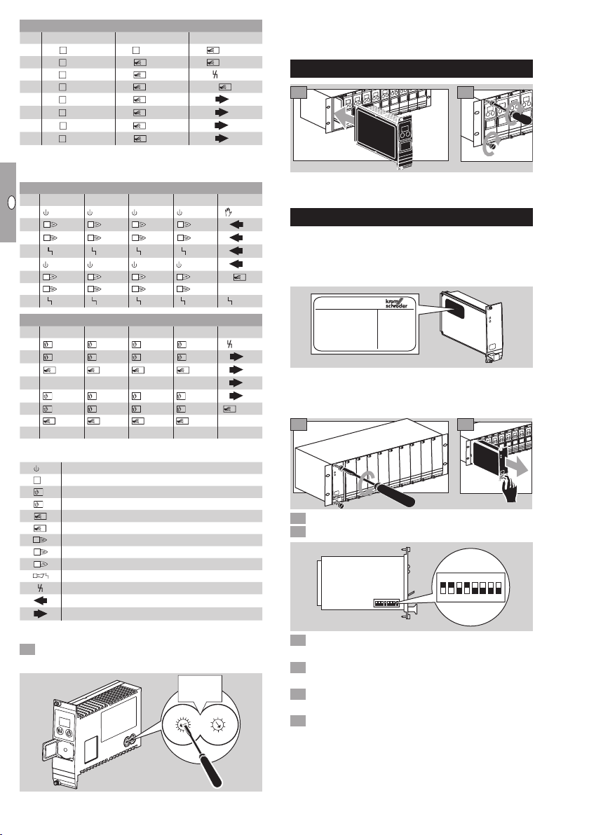
Installing the PFA
1
▷ Ensure that the PFA is correctly inserted.
1
2
3
4
Replacing the PFA
▷
The old PFA 700 (Order No. 84395100 – see type
label) can be replaced with the new PFA 700 (Order
No. 84395101 or 84395102) in the module subrack
BGT SA-9U/1DP (Order No. 84402283).
84395100
1
2
3
4
▷ To increase the EMC interference immunity, the new
Profibus plug supplied must be used for the new PFAs
(Order No. 84395101 or 84395102).
Check the voltage.
4 Read off the Profibus address on the old PFA.
5 Accept and set the Profibus address on the new PFA
– see page 4 (Address setting).
6 Install the new PFA – see page 4 (Installing the
PFA).
7 Check the operating parameters for manual mode on
the new PFA and adjust where applicable.
8 Replace the Profibus plug on the BGT with the Profi-
bus plug with shielding capacitor – see page 12
(Profibus plug for PFA).
GB-4
2
ON
12345678
Page 5

GB
F
NL
I
E
Labelling the PFA
▷ Each PFA can be labelled individually.
Attach label or sticker to the space provided on the
handle of the fieldbus interface.
When using operating mode parameters set at the
factory
PFA 700, PFA 70
Parameter 43 = 1
4 Press the Reset/Information button for 1 s.
▷ The display indicates step
▷
The PFUs start the burners and open the air valve
04
.
via the external control system (programming of the
operating mode at the factory).
PFA
Zone 3
▷
The size of this space is 28 × 18 mm
(1.10×0.71").
Commissioning
▷ During operation, the 7-segment display shows the
program status:
Unit Off
––
Programming mode
(blinking dots) Manual mode
0.0.
Normal operation
OP
Profibus fault
P
WARNING
Check the system for tightness before commissioning.
Do not start the PFA until the downstream automatic
burner control units have been properly commissioned.
Switch on the system.
▷ The display indicates
––
.
Switch on the PFA by pressing the On/Off button.
▷
As soon as the flashing display P goes out and
the display indicates
, the data traffic is operating.
OP
Manual operation
The PFA can be started in manual mode for burner adjust-
ment or for fault-finding:
Using the opto-adapter and the BCSoft software, the
▷
operating mode parameters for manual mode can
be changed.
CAUTION
If parameters are changed, stick the supplied adhesive
When using adjusted operating mode parameters
ON/OFF operating mode
PFA 700 in conjunction with PFU 760
Parameter 43 = 2
4 Press the Reset/Information button for 1 s.
▷ The display indicates step
03
.
▷ The PFUs start the burners.
5 Press the Reset/Information button for 1 s.
▷ The display indicates step
.
00
▷ The PFUs switch off all the burners.
▷ By pressing the Reset/Information button repeatedly,
the PFUs are activated to switch between burner start
(the display indicates step
indicates step
00
03
) or burner off (the display
).
PFA 700 in conjunction with PFU 760..L
Parameter 43 = 3
4 Press the Reset/Information button for 1 s.
▷ The display indicates step
01
.
▷ The PFUs start the burner pre-purge procedure.
WARNING
The pre-purge duration is not included in the program.
Pre-purge until the combustion chamber has been adequately ventilated.
5 Press the Reset/Information button for 1 s.
▷ The display indicates step
▷ The PFUs start the burners.
6 Press the Reset/Information button for 1 s.
▷ The display indicates step
▷ The PFUs switch off all the burners.
▷ By pressing the Reset/Information button repeatedly,
the PFUs are activated to switch between pre-purge
(the display indicates step
indicates step
step
00
03
) or burner off (the display indicates
).
.
03
.
00
burner start (the display
01
),
label “Changed parameters” on the PFA– see page12
(Accessories).
Switch on the system.
Apply voltage to terminals 19 and 20 on the terminal
strip X10.
Switch on the PFA by pressing the On/Off button while
holding down the Reset/Information button. Hold the
button until both dots in the display start to blink.
▷ The display indicates
▷
Deactivate manual mode by pressing the On/Off
0.0.
.
button.
▷
back to normal operation automatically.
After 5 minutes in manual mode, the PFA switches
GB-5
Page 6

GB
F
NL
I
E
PFA 70 in conjunction with PFU 780..L
Parameter 43 = 3
4 Press the Reset/Information button for 1 s.
▷ The display indicates step
01
.
▷ The PFUs start the burner pre-purge procedure.
WARNING
The pre-purge duration is not included in the program.
Pre-purge until the combustion chamber has been adequately ventilated.
5 Press the Reset/Information button for 1 s.
▷ The display indicates step
.
02
▷ The PFUs start the pilot burners.
6 Press the Reset/Information button for 1 s.
▷ The display indicates step
▷
The PFUs start the main burners, the pilot burners
03
.
remain switched on.
7 Press the Reset/Information button for 1 s.
▷ The display indicates step
.
00
▷ The PFUs switch off all the burners.
▷ By pressing the Reset/Information button repeatedly,
the PFUs are activated to switch between pre-purge
(the display indicates step
display indicates step
display indicates step
indicates step
00
).
pilot burner start (the
01
),
main burner start (the
02
),
03
) or burner off (the display
High/Low operating mode
PFA 700 in conjunction with PFU 760..L
Parameter 43 = 4
4 Press the Reset/Information button for 1 s.
▷ The display indicates step
01
.
▷ The PFUs start the burner pre-purge procedure.
WARNING
The pre-purge duration is not included in the program.
Pre-purge until the combustion chamber has been adequately ventilated.
5 Press the Reset/Information button for 1 s.
▷ The display indicates step
▷ The PFUs start the burners.
6 Press the Reset/Information button for 1 s.
▷ The display indicates step
▷ The PFUs 760..L activate the external air valves, the
burners switch to high-fire rate.
7 Press the Reset/Information button for 1 s.
▷ The display indicates step
▷
The PFUs 760..L deactivate the external air valves,
the burners switch to low-fire rate.
▷
Each time the Reset/Information button is pressed, the
air valves are opened (the burners switch to high-fire
rate, the display indicates
ers switch to low-fire rate, the display indicates
.
03
.
04
.
03
) or closed (the burn-
04
03
PFA 70 in conjunction with PFU 780..L
Parameter 43 = 4
4 Press the Reset/Information button for 1 s.
▷ The display indicates step
01
.
▷ The PFUs start the burner pre-purge procedure.
WARNING
The pre-purge duration is not included in the program.
Pre-purge until the combustion chamber has been adequately ventilated.
5 Press the Reset/Information button for 1 s.
▷ The display indicates step
.
02
▷ The PFUs start the pilot burners.
6 Press the Reset/Information button for 1 s.
▷ The display indicates step
▷
The PFUs start the main burners, the pilot burners
03
.
remain switched on.
7 Press the Reset/Information button for 1 s.
▷ The display indicates step
.
04
▷ The PFUs 780..L activate the external air valves, the
main burners switch to high-fire rate.
8 Press the Reset/Information button for 1 s.
▷ The display indicates step
▷
The PFUs 780..L deactivate the external air valves,
03
.
the main burners switch to low-fire rate.
▷
Each time the Reset/Information button is pressed, the
air valves are opened (the burners switch to high-fire
rate, the display indicates
) or closed (the burn-
04
ers switch to low-fire rate, the display indicates
Faults
DANGER
Electric shocks can be fatal! Before working on possible
live components, ensure the unit is disconnected from
the power supply.
Fault-clearance must only be undertaken by authorized,
trained personnel.
▷
Faults may be cleared only using the measures described below.
▷
If the PFA does not respond even though all faults
have been remedied: remove the unit and return it to
the manufacturer for inspection.
? Faults
! Cause
• Remedy
? The 7-segment display does not light up.
! Mains voltage is not applied.
• Check the wiring, apply mains voltage (see type label).
.
)
03
.
)
GB-6
Page 7

GB
F
NL
I
E
? The display blinks and indicates
P
or
? A bus fault is indicated on the automation sys-
tem.
! The PROFIBUS DP data traffic has suffered a fault.
! Bus cable interrupted.
• Check bus cable.
! Bus cable connections confused in the plug.
• Check the wiring.
! A and B cables confused.
• Check cables.
! Terminal resistors connected incorrectly.
• Switch on the terminal resistors on the first and last
station in the segment and switch them off for all other
stations.
! Incorrect PROFIBUS address set.
• Correct the address setting – switch the unit off and
then on again to save the address.
! Bus cables too long.
• Reduce cable length or baud rate – see page 5
(Commissioning).
▷
If the transfer rate is reduced, remember that this
will increase the signal running times to and from the
individual units.
! Poor shielding.
• The shield must be connected to the shield clips in
the PROFIBUS DP plugs in full and over a wide area.
! Poor equipotential bond.
• The PROFIBUS DP shield should be connected at all
points to the same ground potential by grounding the
BGT. If necessary an equipotential bond cable must
be laid.
! If faults only occur sporadically in the PROFIBUS DP
system, and are mostly only indicated briefly in the
bus master, the terminal resistors, shielding, cable
lengths/routes, equipotential bond and the use of
interference-suppressed ignition electrode plugs (1kΩ)
in particular should be checked.
▷
Further notes on building PROFIBUS DP networks
are set out in the instructions for the automation
system or, for example, in the “Installation Guideline
for PROFIBUS DP/FMS”, available from the PUO
(PROFIBUS User Organization).
? All the burners are constantly in operation, re-
gardless of data traffic.
! The PFA is set to manual mode.
• Switch the PFA to “normal operation”.
? The display indicates
.
! Profibus module fault.
• Remove the unit and return it to the manufacturer.
? The display indicates
95, 96, 97, 98
30, 31, 34, 80, 89, 94
.
99
or
! Internal faults.
• Remove the unit and return it to the manufacturer.
Technical data
BGT
Weight: 2.3 kg.
PFA
Front width 8 depth units = 40.6 mm.
Overall height 3 height units = 128.4 mm.
Ambient temperature: -20°C to +60°C.
4 digital inputs: 24 V DC, ± 10%, < 10 mA.
4 digital outputs for contr
olling small relays 24 V, max.
250 mW (10 mA).
Mains voltage:
220/240 V AC, -15/+10%, 50/60 Hz,
110/120 V AC, -15/+10%, 50/60 Hz,
for grounded and ungr
ounded mains.
Weight: approx. 0.75 kg.
Designed lifetime
This information on the designed lifetime is based on using
the product in accordance with these operating instructions. Once the designed lifetime has been reached, safetyrelevant products must be replaced.
Designed lifetime (based on date of manufacture) in accordance with EN 230 and EN 298 for PFA/BGT: 10 years.
You can find further explanations in the applicable rules and
regulations and on the afecor website (www.afecor.org).
This procedure applies to heating systems. For thermopro-
cessing equipment, observe local regulations.
Logistics
Transport
Protect the unit from external forces (blows, shocks, vibration). On receipt of the product, check that the delivery is
complete, see page 2 (Part designations). Report any
transport damage immediately.
Storage
Store the product in a dry and clean place.
Storage temperature: see page 7 (Technical data).
Storage time: 6 months in the original packaging before
using for the first time. If stored for longer than this, the
overall service life will be reduced by the corresponding
amount of extra storage time.
Packaging
The packaging material is to be disposed of in accordance
with local regulations.
Disposal
Components are to be disposed of separately in accordance with local regulations.
,
GB-7
Page 8

sk1
PFU 7xx
GB
F
NL
I
E
BGT SA-9U/DP connection diagram
BGT SA-9U/1DP700 (8 440 229 1)
30e
26e
22a
30a
20c
230 V
28c
26a
18a
10e
12e
14a
14e
10a
12a
10c
12c
32c
24c
c2
c1
F1
1
2
PFU 7xx
l
22e
sk1
v1
16c
v2
18e
2a
4a
2e
4e
2c
1
4c
6a
6e
2
..8, ..7,
..6, ..5,
..4, ..3,
9
..2
30e
26e
22a
30a
20c
230 V
28c
26a
18a
10e
12e
14a
14e
10a
12a
10c
12c
32c
24c
c2
c1
F1
1
2
X9
1
2
3
4
5
6
7
8
X9.5
1
2
X9.3
UVS
3
X10.21
1
X9.6
N
ZI
V1
V2
1
2
1
DI
GB-8
UVS
1
2
3
X1.5
X1.3
X10.21
X1.6
N
1
ZI
V1
V2
Page 9

sk1
GB
F
NL
I
E
v1
v2
7xx
l
22e
16c
18e
2a
4a
2e
4e
2c
1
4c
6a
6e
2
1
+24 V
1. PFU
9. PFU
1. PFU
9. PFU
1. PFU
9. PFU
1. PFU
9. PFU
1. PFU
5. PFU
6. PFU
9. PFU
PFU
…
…
…
…
…
…
24 V
0 V
15b
16b
1c
9c
10c
18c
1a
9a
10a
18a
19a
23a
20c
23c
19c
17b
30c
A
P
PFA 700
C
I/O
32b
30a
PROFIBUS DP
8b
11b
12b
14b
18b
1
19b
2
20b
3
21b
4
22b
23b
1
24b
2
25b
3
26b
4
L1
N
VP
RxD/TxD-P
RxD/TxD-N
DGND
+24 V
+24 V
+24 V
+24 V
0 V
K2
K4
PROFIBUS DP
ex
ex
ex
ex
ex
K1
K3
k5
X1
2
30e
X10
11
12
13
K5
14
1
2
3
4
5
6
7
8
15
16
17
18
19
20
21
22
PFU 7xx
1…9
X10
1
2
3
4
5
6
7
8
9
max. 1 A, 24 V
E1 E2 E3 E4
COM
10
k1
k2
k3
k4
+24 V
0 V
ex
ex
DI
PE
GB-9
N
L1
Page 10

sk1
PFU 780
GB
F
NL
I
E
BGT SA-8U/DP connection diagram
BGT SA-8U/1DP710 (84402292)
30e
26e
22a
30a
20c
230 V
28c
26a
18a
10e
12e
14a
14e
10a
12a
10c
12c
32c
24c
c2
c1
F1
sk1
1
2
PFU 780
l
22e
v1
16c
v2
18e
2a
4a
2e
4e
2c
1
4c
6a
6e
2
..7, ..6,
..5, ..4,
..3, ..2,
8
30e
26e
22a
30a
20c
230 V
28c
26a
18a
10e
12e
14a
14e
10a
12a
10c
12c
32c
24c
c2
c1
F1
1
2
X8
1
2
3
4
5
6
7
8
X8.5
1
2
X8.3
UVS
3
X10.21
1
X8.6
N
ZI
V1
V2
1
2
1
DI
GB-10
UVS
1
2
3
X1.5
X1.3
X10.21
X1.6
N
1
ZI
V1
V2
Page 11

sk1
l
GB
F
NL
I
E
22e
v1
16c
v2
18e
2a
4a
2e
4e
2c
1
4c
6a
6e
2
1
+24 V
1. PFU
8. PFU
1. PFU
7. PFU
8. PFU
1. PFU
8. PFU
1. PFU
8. PFU
1. PFU
8. PFU
1. PFU
2. PFU
3. PFU
5. PFU
6. PFU
8. PFU
1. PFU
5. PFU
6. PFU
8. PFU
PFU
...
...
...
...
...
...
...
...
...
24 V
0 V
15b
16b
1c
8c
27a
10c
17c
1a
8a
10a
17a
27c
27b
24a
26a
24c
26c
19a
23a
20c
22c
19c
17b
30c
32b
L1
30a
N
1
1b
7b
2
A
1
2
P
C
PROFIBUS DP
8b
11b
12b
14b
18b
1
19b
2
20b
3
21b
4
22b
I/O
23b
1
24b
2
25b
3
26b
4
PFA 710
VP
RxD/TxD-P
RxD/TxD-N
DGND
+24 V
+24 V
+24 V
+24 V
0 V
K2
K4
PROFIBUS DP
ex
ex
ex
ex
ex
K1
K3
k5
X1
2
30e
X10
11
12
13
K5
14
1
2
3
4
5
6
7
8
15
16
17
18
19
20
21
22
PFU 7xx
1…8
X10
1
2
3
4
5
6
7
8
9
max. 1 A, 24 V
E1 E2 E3 E4
COM
10
k1
k2
k3
k4
+24 V
0 V
ex
ex
DI
PE
GB-11
N
L1
Page 12

GB
F
NL
I
E
Accessories
“Changed parameters” stickers
D-49018 Osnabrück, Germany
Achtung, geänderte Parameter!
Die Angaben auf dem Typenschild
gelten nicht mehr in vollem Umfang.
Aktuelle Parameter direkt auslesen.
Important, changed parameters!
The details on the type label are no
longer completely accurate. Read the
current parameters direct from the
unit.
Attention, paramètres modifiés !
Les informations figurant sur la plaque
signalétique ne sont plus valables
dans leur intégralité. Veuillez vous
référer directement aux paramètres
actualisés.
Affix on the PFA if parameters set at the factory have been
changed.
100 pcs, Order No.: 74921492.
Opto-adapter PCO 00 including BCSoft CD-ROM
Order No.: 74960625.
Bluetooth adapter PCO 00 including BCSoft
CD-ROM
Order No.: 74960617.
▷
Downloading the BCSoft software, see
www.docuthek.com
Profibus plug for PFA
For connecting Profibus stations to the Profibus bus cable. To replace existing PROFIBUS plug connectors if a
new PFA700 is operated in an old module subrack with
the OrderNo.84402283 in order to improve EMC– see
page4 (Replacing the PFA).
A B A’ B’
▷ Data cablesA and B must not be reversed (A’ is
connected toA, B’ is connected toB).
▷
The power supply for the bus terminator is provided by
the PFA. The bus terminator can be connected in the
PROFIBUS plug. If the switch is set toON, outputsA’
andB’ are switched off.
▷ To ensure optimum cable clamping, insert one of the
fillers supplied into the housing depending on the
thickness of the cables.
Scope of delivery: Profibus plug with shielding capacitor,
fillers for cable clamping,
Order No.: 74960621.
Certification
Declaration of conformity
We, the manufacturer, hereby declare that the products
BGT and PFA comply with the essential requirements of
the following Directives and Standards.
Directives:
– 2006/95/EC,
– 2004/108/EC,
– designed for applications pursuant to
Directive 98/37/EC.
Standards:
– EN 50170-2,
– EN 60730.
The production is subject to a Quality Management System
pursuant to DIN EN ISO 9001.
Elster GmbH
ON OFF
5
5
15
Data cable:
fold back the
woven shield.
A and B =
incoming
cables, A’ and
B’ = outgoing
1stand last
stations = ON,
other stations
= OFF
cables
Contact
Contact
If you have any technical questions, please contact your
local branch office/agent. The addresses are available on
the Internet or from ElsterGmbH.
We reserve the right to make technical modifications in
the interests of progress.
Scan of the Declaration of conformity (D, GB) – see
www.docuthek.com
Eurasian Customs Union
The product BGT meets the technical specifications of the
Eurasian Customs Union.
Elster GmbH
Strotheweg 1, D-49504 Lotte (Büren)
Tel. +49 541 1214-0
Fax +49 541 1214-370
hts.lotte@honeywell.com, www.kromschroeder.com
GB-12
 Loading...