

Page 1
D
Labor-Sicherheitsventil
LSV
Labor-Sicherheitsstrecke
K-LSV
Gas- und Strommangelsicherung zum Sichern von Gasentnahmestellen für Laboratorien,
naturwissenschaftliche technische Unterrichtsräume oder
gewerbliche Küchen.
Überprüft, ob alle Gasverbraucher abgesperrt sind, bevor die
Gaszufuhr freigegeben wird.
Betriebsanleitung
● Bitte lesen und aufbewahren
Einbauen
Verdrahten
Einstellen
Warten
Störungen beheben
nur durch autorisiertes Fachpersonal!
WARNUNG! Unsachgemäßer Einbau,
Einstellung, Veränderung, Bedienung
oder Wartung kann Verletzungen oder
Sachschäden verursachen.
Anleitung vor dem Gebrauch lesen. Dieses Gerät muß nach den
geltenden Vorschriften installiert
werden.
DVGW-Regelwerk Arbeitsblatt
G 621 oder G 634 beachten.
Safety valve for
laboratories LSV
Safety line for
laboratories K-LSV
Gas shortage and low pressure
gas cut-out for securing gas
tapping points in laboratories,
natural science workshops and
catering kitchens.
Check that all gas devices are
switched off before the gas
supply can be started.
Operating instructions
● Please read and keep in a
safe place
Installation
Wiring
Adjusting
Maintaining
Rectification of faults
By authorised trained personnel
only!
WARNING! Incorrect installation,
adjustment, modification, operation or maintenance may cause injury or material damage.
Read the instructions before use.
This unit must be installed in accordance with the regulations in
force.
DVGV Codes of Practice G 621 or
G 634 have to be observed.
Konformitätsbescheinigung
Wir erklären als Hersteller, daß das
Produkt LSV, gekennzeichnet mit
der Produkt-ID-Nr. CE-92-0063001-01 die grundlegenden Anforderungen folgender Richtlinien erfüllt:
– 90/396/EWG in Verbindung mit
EN 126 und prEN 1854,
– 89/392/EWG,
– 73/23/EWG in Verbindung mit
den einschlägigen Normen,
– 89/336/EWG in Verbindung mit
EN 55104.
Es stimmt überein mit dem bei der
zugelassenenen Stelle 0063 geprüften Baumuster.
Eine umfassende Qualitätssicherung
ist gewährleistet durch ein zertifiziertes Qualitätsmanagementsystem
nach DIN EN ISO 9001 gemäß Anhang II Absatz 3 der Richtlinie
90/396/EWG.
G. Kromschröder AG
Osnabrück
➚
Certificate of conformity
We, the manufacturer, hereby declare that the product LSV, marked
with product ID No. CE-92-0063001-01, complies with the essential
requirements of the following Directives:
– 90/396/EEC in conjunction with
EN 126 and prEN 1854,
– 89/392/EEC,
– 73/23/EEC in conjunction with
the relevant standards,
– 89/336/EEC in conjunction with
EN 55104.
The relevant product corresponds to
the type tested by the notified body
0063.
Comprehensive quality assurance is
guaranteed by a certified Quality
System pursuant to DIN EN ISO
9001 according to annex II, paragraph 3 of Directive 90/396/EEC.
G. Kromschröder AG
Osnabrück
➚
Labor-Sicherheitsventil LSV
Labor-Sicherheitsventil mit Schmutzfänger, 1. Magnetventil, 2. Magnetventil mit Bypass und Druckwächter.
Der Ausgangsdruck am LSV ist ungeregelt.
Labor-Sicherheitsstrecke K-LSV
LSV mit Kugelhahn und Druckregler.
Der Ausgangsdruck am K-LSV ist
geregelt.
für Erdgas, Stadtgas und Flüssiggas
(gasförmig)
➔ max. Eingangsdruck p
e max
:
100 mbar
➔ min. Eingangsdruck
bei Erdgas und Flüssiggas
p
e min
: 15 mbar
(Schaltpunkt: 12 mbar)
bei Stadtgas p
e min
: 7 mbar
(Schaltpunkt: 4 mbar).
Schaltkasten
SK 32
zur Ansteuerung von LSV oder
K-LSV im Laborbereich.
SK 10
zur Ansteuerung eines zusätzlichen
Magnetventils VG als zentrale Absperreinrichtung im Laborbereich.
SK 42
zur Ansteuerung von LSV oder
K-LSV im gewerblichen Küchenbereich.
SK 41
zur Ansteuerung eines Magnetventils VG im gewerblichen Küchenbereich.
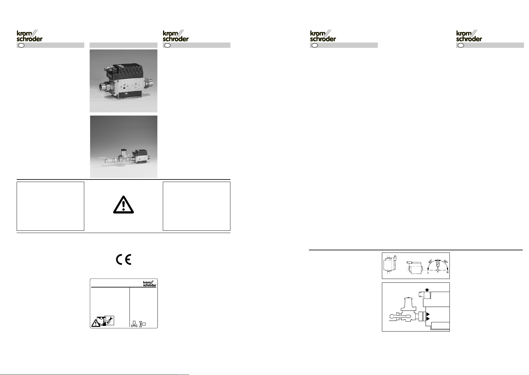
Einbauen
➔ Einbaulage in senkrechter Lei-
tung: beliebig; in waagerechter
Leitung; gekippt bis max. 90°
links/rechts, nicht über Kopf.
● Absperreinrichtung (Kugelhahn
oder Magnetventil) außerhalb des
Labors einbauen.
● Kugelhahn direkt vor dem LSV,
K-LSV einbauen, für Wartungsarbeiten.
● Verschlußkappen entfernen.
● Durchflußrichtung 1 beachten –
Pfeile am Gehäuse.
➔ Volumen der Rohrleitungen zwi-
schen LSV, K-LSV und Verbraucher durch kurze Leitungen klein
halten.
➔ Das Gehäuse darf kein Mauer-
werk berühren – Mindestabstand
20 mm – nach dem Einbau müssen zugänglich sein: Die Schrauben 2 für die Stecker und bei
K-LSV die Einstellschraube 3 für
den Druckregler GDJ.
Safety valve for laboratories LSV
Safety valve for laboratories with dirt
trap, 1
st
solenoid valve, 2ndsolenoid
valve with bypass and pressure switch.
The outlet pressure from the LSV is
not controlled.
Safety line for laboratories K-LSV
LSV with manual valve and governor.
The outlet pressure from the K-LSV
is controlled.
For natural gas, town gas and LPG
(gaseous).
➔ Max. inlet pressure p
e max
:
100 mbar
➔ Min. inlet pressure
on natural gas and LPG version
p
emin
: 15 mbar
(switching point 12 mbar)
on town gas version p
e min
: 7 mbar
(switching point 4 mbar)
Switch box
SK 32
for controlling LSV or K-LSV in
laboratories.
SK 10
for controlling an additional solenoid
valve VG to act as a central shut-off
valve in laboratories.
SK 42
for controlling LSV or K-LSV in
catering kitchens.
SK 41
for controlling a solenoid valve VG in
catering kitchens.
Installation
➔ Installation position in vertical
pipework: arbitrary; in horizontal
pipework: tilted to a maximum
angle of 90° to the left or right,
not upside down.
● Install the shut-off device (manual
valve or solenoid valve) outside
the laboratory.
● Install the manual valve immediately before the LSV or K-LSV
for servicing work.
● Remove the screw caps.
● Check direction of flow 1 – see
arrows on housing.
➔ Keep the volume of the pipelines be-
tween the LSV, K-LSV and consumers small by using short pipelines.
➔ The housing must not be in
contact with masonry (minimum
distance 20 mm) and must be
accessible after installation: the
screws 2 for the plugs and, for
the K-LSV, the adjusting screw 3
for the governor GDJ.
5.2.1.4 Edition 12.95
G. Kromschröder AG
Postfach 2809
49018 Osnabrück
D – 49018 Osnabrück, Germany
CE-92-0063-001-01
1
2
3
AKT
GDJ
34426600 10.00 Fx/ivd 2.000
GB
D
GB
Page 2
- 2 -
● Gerät spannungsfrei einbauen –
passenden Schraubenschlüssel
verwenden – Gerät nicht als Hebel benutzen!
➔ Schaltkasten SK vor oder im La-
bor- bzw. Schulungsraum befestigen. An den Schaltkästen SK
können zusätzlich Not-Aus-Taster NSA, NSU (ohne Schlüssel),
NTA, NTU (mit Schlüssel) angeschlossen werden.
➔ Magnetventil VG einbauen nach
eigener Betriebsanleitung.
Dichtheit prüfen
● LSV abschalten.
➔ Ein Druck über 150 mbar be-
schädigt das LSV!
Eingang:
● Kugelhahn schließen.
● Am Meßpunkt A max. 150 mbar
aufgeben.
● Rohrende am Eingang abseifen.
● Kugelhahn wieder öffnen.
Ausgang:
● Gasleitung am Verbraucher absperren.
● Am Meßpunkt B max. 150 mbar
aufgeben.
● Rohrende am Ausgang abseifen.
Eingangsdruck p
e
prüfen:
● Max. 100 mbar an der Meßstelle A.
➔ Magnetventil VG Dichtheit prüfen
nach eigener Betriebsanleitung.
Verdrahten
➔ Die Angaben auf dem Typen-
schild müssen mit der Netzspannung übereinstimmen: Toleranz
–15 %/+10 %.
➔ Die elektrische Leistung ist beim
Einschalten und beim Dauerbetrieb gleich,
Einschaltdauer 100 %,
cos ϕ = 1,
Leistung bei 220 V: 38 VA,
Leistung bei 240 V: 46 VA.
● Zuleitung spannungsfrei schalten.
➔ Stecker nacheinander verdrah-
ten, damit sie nicht vertauscht
werden können!
A = grau für Druckwächter
B = schwarz für Ventile
● Schraube lösen.
● Stecker abnehmen.
● Schraube ganz herausnehmen.
● Mit Schraubendreher Steckerein-
satz herausnehmen.
➚
● Install the device with no stress
(use suitable spanner). Do not
use the device as a lever.
➔ Secure the switch box SK out-
side or inside the laboratory or
teaching workshop. An Emergency
Stop button NSA, NSU (without a
key), NTA, NTU (with a key) can
also be connected to the switch
boxes SK.
➔ Install the solenoid valve VG using
the separate Operating instructions.
Check for tightness
● Switch off the LSV.
➔ A pressure of over 150 mbar
will damage the LSV.
Inlet:
● Close the manual valve.
● Apply a max. pressure of 150 mbar
at test point A.
● Use soap solution to check for leaks
at the end of the pipe at the inlet.
● Open the manual valve again.
Outlet:
● Shut off the gas pipe at the consumer.
● Apply a max. pressure of 150 mbar
at test point B.
● Use soap solution to check for leaks
at the end of the pipe at the outlet.
Check the inlet pressure p
e
:
● Max. 100 mbar at test point A.
➔ Check solenoid valve VG for
leaks using separate Operating
instructions.
Wiring
➔ The details on the type label must
be identical with the mains voltage: Tolerance –15%/+10%.
➔ The electrical power is the same
when the unit is switched on and
during continuous operation,
ON duration 100%,
cos ϕ = 1,
power at 200 V: 38 VA,
power at 240 V: 46 VA.
● Disconnect the cable from the
mains power supply.
➔ Wire the plugs in sequence so
that they cannot be mixed up.
A = Grey for pressure switch
B = Black for valves
● Undo the screw.
● Remove the plug.
● Take out the screw completely.
● Take out the plug insert with a
screwdriver.
➚
● Kabel – max. 10 mm Ø – durch
PG-Verschraubung führen und
anschließen:
➔ Verdrahten nach beiliegendem
Schaltplan.
SK 32 oder SK 42 für LSV, K-LSV
SK 10 oder SK 41 für VG.
➔ Beim Einsetzen der Stecker-
einsätze auf richtige Lage achten:
Schutzkontakte zur Mitte des
Gerätes.
➔ Der Magnetkörper wird beim
Betrieb warm – je nach Umgebungstemperatur und Spannung bis zu 90 °C.
In Betrieb nehmen
VG mit SK 10 in Betrieb nehmen.
➔ Die nachfolgende Rohrleitung
wird nicht auf Dichtheit überprüft.
● Kugelhahn öffnen.
● Alle Hähne am Lehrertisch
schließen.
● VG über Schaltkasten SK 10
elektrisch einschalten:
Schlüssel S1 einstecken, auf I
drehen und wieder abziehen.
➔ Leuchtmelder H1 „Betrieb“
leuchtet.
● Hähne am Lehrertisch öffnen.
● Gas entzünden.
● Taster S2 „Aus“ drücken oder
● Not-Aus-Taster NSA, NSU, NTA,
NTU drücken: Die Gaszufuhr wird
unterbrochen.
LSV, K-LSV mit SK 32 in Betrieb
nehmen
● Alle Hähne 5 im Labor schließen.
● Kugelhahn 1 öffnen.
SK 32 einschalten:
● Schlüssel S1 einstecken, auf I dre-
hen und Schlüssel wieder abziehen.
➔ Leuchtmelder H1 „Netz Ein“
leuchtet.
➔ Leuchtdrucktaster S2 „Start“
drücken und halten:
➔ Das 1. Magnetventil Y1 öffnet,
der Druck baut sich über die Bypassdüse 4 auf und der Druckwächter S4 schaltet das 2. Magnetventil Y2 ein (Dauer siehe
Befülldiagramm).
➔ Wenn der Leuchtdrucktaster H2
leuchtet, ist die Anlage betriebsbereit, Leuchtdrucktaster S2 loslassen.
● Hähne 5 öffnen, Bunsenbrenner
anzünden.
➔ Bei K-LSV Ausgangsdruck ein-
stellen – siehe unten.
Anlage abschalten auch im Notfall:
● Taster S3 „Aus“ drücken oder
● Not-Aus-Taster NSA, NSU, NTA,
NTU drücken: Die Gaszufuhr wird
unterbrochen.
● Thread the cable (max. 10 mm in
diameter) through the PG cable
gland and connect it.
➔ Wire using the enclosed circuit
diagram.
SK 32 or SK 42 for LSV, K-LSV,
SK 10 or SK 41 for VG.
➔ When installing the plug inserts,
ensure they are in the correct position: the safety contacts must
point towards the centre of the
unit.
➔ The magnetic body becomes
warm when operational – up to
90°C depending on the ambient temperature and voltage.
Commissioning
To commission the VG with SK 10:
➔ The downstream pipeline is not
checked for leaks:
● Open the manual valve.
● Close all the valves on the
teacher’s bench.
● Switch on the electrical system of
the VG using switch box SK 10:
Insert key S1, turn to position I
and remove the key again.
➔ Control lamp H1 “Operation” will
be lit.
● Open the valves on the teacher’s
bench.
● Light the gas.
● Press button S2 “Off” or
● Press Emergency Stop button
NSA, NSU, NTA, NTU: the gas
supply will be stopped.
To commission the LSV, K-LSV
with SK 32:
● Close all the valves 5 in the laboratory.
● Open manual valve 1.
To switch on SK 32:
● Insert key S1, turn to position I
and remove the key again.
➔ Control lamp H1 “Mains on” will be lit.
➔ Press luminous push-button S2
“Start” and hold it:
➔ The 1
st
solenoid valve Y1 opens, the
pressure builds up through the bypass nozzle 4and pressure switch S4
switches on the 2
nd
solenoid valve Y2
(see filling diagram for duration).
➔ When the luminous push-button
H2 is lit, the system is ready for
operation, release luminous
push-button S2.
● Open the valves 5, light the
Bunsen burner.
➔ Set the outlet pressure on the
K-LSV – see below.
To switch off the system, including in
emergencies:
● Press button S3 “Off” or
● Press the Emergency Stop but-
ton NSA, NSU, NTA, NTU: the
gas supply will be stopped.
V1
V2
1N
3L
V1
1NC
2NO
3COM
2L
V2
PE
PE
1
3
2
1
3
2
A
B
0
I
S1 H1 S2
SK 10
LSV
5
Y2Y1
31
2
4
S4
0
I
S1 H1 S2H2S3
SK 32
D
GB
D
GB
Page 3

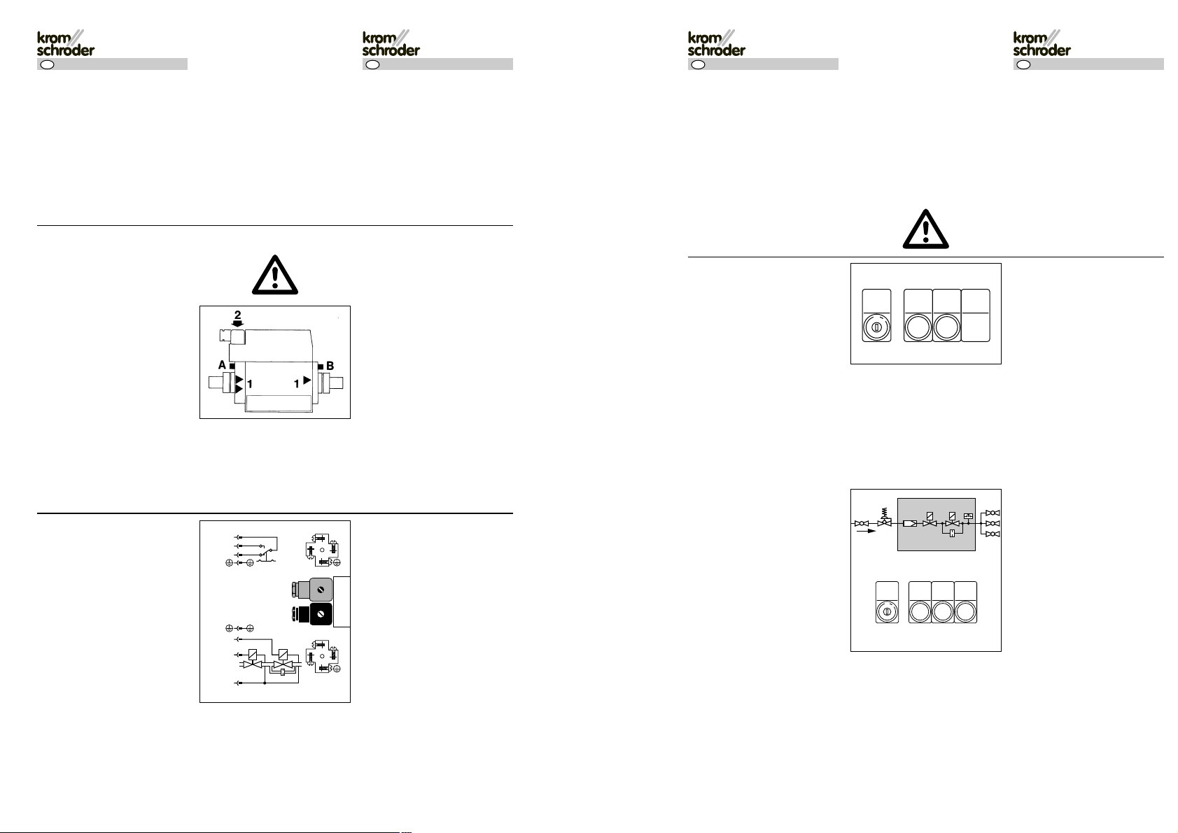
VG mit SK 41 in Betrieb nehmen.
➔ Die nachfolgende Rohrleitung
wird nicht auf Dichtheit überprüft.
● Alle Hähne am Herd schließen.
● Kugelhahn 1 öffnen.
● Externen Hauptschalter und Ab-
zugshaube 2 einschalten.
➔ Druckwächter S6 „Gas min.“
schaltet, dann leuchtet der
Leuchtmelder H2 „Betriebsbereit“.
● Druckwächter S5 einstellen, so
daß er schaltet, wenn die Abzugshaube 2 läuft und der Filter 3
sauber ist.
● Druckwächter S4 etwas höher
als S5 einstellen, so daß er erst
schaltet, wenn der Filter verschmutzt ist.
● Ventil über Schaltkasten SK 41
elektrisch einschalten:
Schlüssel S1 einstecken, auf I
drehen und wieder abziehen.
➔ Der Leuchtmelder H3 „Gasventil
Betrieb“ leuchtet. Nach ca. 30 s
öffnet das Gasventil.
● Herd anzünden.
● Taster S2 „Aus“ drücken oder
● Not-Aus-Taster NSA, NSU, NTA,
NTU drücken: Die Gaszufuhr wird
unterbrochen.
LSV, K-LSV mit SK 42 in Betrieb
nehmen
● Alle Hähne am Herd schließen.
● Kugelhahn 1 öffnen.
● Externen Hauptschalter und Ab-
zugshaube 5 einschalten.
● Druckwächter S6 einstellen, so
daß er schaltet, wenn die Abzugshaube 5 läuft und der Filter 6
sauber ist.
● Druckwächter S5 etwas höher
als S6 einstellen, so daß er erst
schaltet, wenn der Filter verschmutzt ist.
SK 42 einschalten:
● Schlüssel S1 einstecken, Schlüs-
seltaster auf I drehen und Schlüssel wieder abziehen.
➔ Leuchtmelder H2 „Betriebsbereit“
leuchtet.
➔ Leuchtdrucktaster S2 „Start“
drücken und halten:
➔ Das 1. Magnetventil Y1 öffnet,
der Druck baut sich über die Bypassdüse 4 auf und der Druckwächter S7 schaltet das 2. Magnetventil Y2 ein (Dauer siehe
Befülldiagramm).
➔ Wenn der Leuchtdrucktaster H3
leuchtet, ist das Gas freigegeben,
Leuchtdrucktaster S2 loslassen.
● Herd anzünden.
➔ Bei K-LSV Ausgangsdruck ein-
stellen – siehe unten.
➚
To start the VG with SK 41:
➔ The downstream pipeline is not
checked for leaks.
● Close all the valves on the stove.
● Open manual valve 1.
● Switch on the external main
switch and vapour hood 2.
➔ The pressure switch S6 “Gas
min.” will switch, then the control
lamp H2 “Standby” will be lit.
● Set pressure switch S5 so that it
switches when the vapour hood
2 is running and the filter 3 is
clean.
● Set pressure switch S4 slightly
higher than S5 so that it does not
switch until the filter is dirty.
● Switch on the electrical system of
the valve using switch box SK 41:
Insert key S1, turn to position I
and remove the key again.
➔ Control lamp H3 “Gas valve oper-
ation” will be lit. The gas valve
opens after approx. 30 seconds.
● Light the stove.
● Press button S2 “Off” or
● Press the Emergency Stop but-
ton NSA, NSU, NTA, NTU: the
gas supply will be stopped.
To commission the LSV, K-LSV
with SK 42:
● Close all the valves on the stove.
● Open manual valve 1.
● Switch on the external main
switch and vapour hood 5.
● Set pressure switch S6 so that it
switches when the vapour hood 5
is running and the filter 6 is clean.
● Set pressure switch S5 slightly
higher than S6 so that it does not
switch until the filter is dirty.
To switch on SK 42:
● Insert key S1, turn to position I
and remove the key again.
➔ Control lamp H2 “Standby” will
be lit.
➔ Press luminous push-button S2
“Start” and hold it:
➔ The 1
st
solenoid valve Y1 opens,
the pressure builds up through
the bypass nozzle 4 and pressure
switch S7 switches on the 2
nd
solenoid valve Y2 (see filling diagram for duration).
➔ When the luminous push-button
H3 is lit, the gas supply is open,
release luminous push-button
S2.
● Light the stove.
➔ Set the outlet pressure on the
K-LSV – see below.
➚
Anlage abschalten auch im
Notfall:
● Taster S3 „Aus“ drücken
oder
● Not-Aus-Taster NSA,
NSU, NTA, NTU drücken:
Die Gaszufuhr wird unterbrochen.
Befülldiagramm
➔ Je nach Volumen der Rohr-
leitung und der Ventile, siehe Tabelle, ist die Befüllzeit
der Anlage unterschiedlich
lang, siehe Diagramm. Falls
noch Druck in der Rohrleitung ist, verkürzt sich die
Auffüllzeit.
t
(s)
maximale Auffüllzeit der
Anlage in Sekunden bis
zur Freischaltung
V
(l)
Volumen der Rohrleitung in
Litern
Das Diagramm gilt nur, wenn:
K-LSV: Ausgangsdruck einstellen:
Der Druckregler ist bei Lieferung auf
20 mbar eingestellt. Erfordern die
Brenner einen anderen Ausgangsdruck:
● Verschlußkappe 1 abziehen.
● Federeinstellschraube 2 mit
Schraubendreher drehen:
im Uhrzeigersinn: Druck höher,
gegen Uhrzeigersinn: Druck niedriger.
● Verschlußkappe 1 wieder auf-
stecken.
● Eingestellter Wert des Ausgangsdruckes auf dem Typenschild 3
notieren.
To switch off the system, including in emergencies:
● Press button S3 “Off” or
● Press the Emergency Stop
button NSA, NSU, NTA,
NTU: the gas supply will
be stopped.
Filling diagram
➔ The filling time of the sys-
tem will differ depending
on the volume of the pipeline and the valves (see
table), see diagram. If there
is still pressure in the
pipeline, the filling time will
be reduced.
t
(s)
Maximum filling time of the
system in seconds until the
gas has been released
V
(l)
Volume of the pipeline in
litres
The diagram is only applicable if:
To adjust the K-LSV outlet
pressure:
The governor is set to 20 mbar
when it is delivered. If the burners require a different outlet pressure:
● Remove screw cap 1.
● Turn the spring adjusting screw 2
with a screwdriver:
clockwise to increase the pressure,
anti-clockwise to reduce the
pressure.
● Fit screw cap 1 again.
● Note the value for the outlet pres-
sure you have set on the type
label 3.
LSV
S5 S6
5
6
Y2Y1
31
2
4
S7
0
I
S1 H1 H2 S2H3S3
SK 42
1
2
3
GDJ
0
I
S1 H1 H2 H3 S2
SK 41
S4 S5
S6
2
3
1
F = Flüssiggas/LPG pe= 50 mbar ps= 12 mbar*
S = Stadtgas/Town gas pe= 8 mbar ps= 4 mbar*
N = Erdgas/Natural gas pe= 20 mbar ps= 12 mbar*
DN Ventilvolumen (l) Rohrlänge in Meter (m)/Pipe length in metres (m)
Valve volume (l) Inhalt der Rohrleitung in Liter (l)/Volume of the pipeline in litres (l)
LSV K-LSV 1 2 3 4 5 6 7 8 9 10
15 – 0,30 0,19 0,38 0,57 0,76 0,95 1,14 1,33 1,52 1,71 1,90
20 0,20 0,30 0,36 0,72 1,08 1,44 1,80 2,16 2,52 2,88 3,24 3,60
25 0,20 0,30 0,57 1,14 1,71 2,28 2,85 3,42 3,99 4,56 5,13 5,70
40 – 0,30 1,36 2,72 4,08 5,44 6,80 8,16 9,52 10,88 12,24 13,60
* werksseitig eingestellt/
set at the factory
D
GB
D
GB
Page 4

- 4 -
Technische Änderungen, die dem
Fortschritt dienen, vorbehalten.
Zentrale Kundendienst-EinsatzLeitung für Deutschland:
G. Kromschröder AG, Osnabrück
Herr Kozlowski
Tel. 05 41/12 14-3 65
Fax 05 41/12 14-5 47
Weitere Unterstützung erhalten Sie
bei der für Sie zuständigen Niederlassung/Vertretung. Die Adresse erfahren Sie im Internet oder bei der
G. Kromschröder AG, Osnabrück.
We reserve the right to make technical modifications in the interests of
progress.
Further support is available from
your local branch office/agent. The
addresses are available on the Internet or from G. Kromschröder AG,
Osnabrück.
G. Kromschröder AG
Postfach 28 09
D-49018 Osnabrück
Strotheweg 1
D-49504 Lotte (Büren)
Tel. 05 41/12 14-0
Fax 05 41/12 14-3 70
info@kromschroeder.com
www.kromschroeder.de
? Faults
! Cause
● Remedy
? The luminous push-button
“Operation” on SK 32 or SK 42
does not light up.
! The gas pressure is too low or
the gas pipe downstream of the
LSV is leaking or
the gas valves are not closed or
the volume is too large (see above).
● Check the gas pressure, gas pipe
and gas valves, rectify the fault
and restart the system.
● Press the luminous push-button
“Start” until the control lamp
“Operation” is lit.
? The control lamp “Filter fault”
is lit on SK 41 or SK 42.
! The filter on the vapour hood is
dirty.
● Replace the filter.
Maintenance
To clean or replace the filter pad
and strainer.
● Close the manual valve.
● Loosen all four screws 1 – take
two of them out fully, depending
on how much space there is, and
pull out the filter section 2.
● Clean or replace the filter pad and
strainer and refit the filter section.
● Check the connection flange for
leaks – soap off the seals.
Apart from this, the safety valves for
laboratories require no maintenance.
We recommend a function check
once a year.
? Störung
! Ursache
● Abhilfe
? Leuchtdrucktaster „Betrieb“
bei SK 32 oder SK 42 leuchtet
nicht:
! Gasdruck zu niedrig oder
Gasleitung hinter LSV undicht
oder
Gashähne nicht geschlossen
oder
Volumen zu groß (siehe oben).
● Gasdruck, Gasleitung und Gashähne kontrollieren, Fehler beheben und die Anlage wieder in Betrieb nehmen:
● Leuchtdrucktaster „Start“ drücken
bis Leuchtmelder „Betrieb“ leuchtet.
? Leuchtmelder „Störung Filter“
bei SK 41 oder SK 42 leuchtet:
! Filter an der Abzugshaube ist ver-
schmutzt.
● Filter austauschen.
Wartung
Filtermatte und Sieb reinigen
oder austauschen.
● Kugelhahn schließen.
● Alle vier Schrauben 1 lockern –
zwei davon, je nach den räumlichen Verhältnissen, ganz herausdrehen und Filterteil 2 herausziehen.
● Filtermatte und Sieb reinigen oder
austauschen und wieder einbauen.
● Anschlußflansch auf Dichtheit
prüfen: Dichtstellen abseifen.
Abgesehen davon sind die LaborSicherheitsventile wartungsfrei.
Zu empfehlen ist eine Funktionsprüfung einmal im Jahr.
2
1
1
D
GB
 Loading...