

Krom Schroder GIK 40TN02-5, GIK 50TN02-5, GIK 15TN02-5B, GIK 25TN02-5B, GIK 40TN02-5B Technical Information
...Page 1
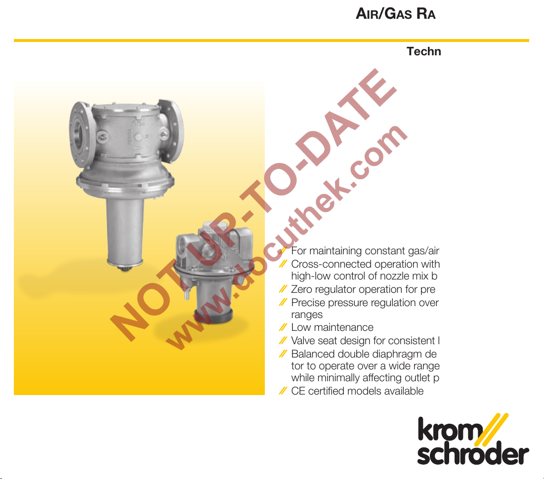
AIR/GAS RATIO CONTROLS
GIK, GIK..B
Technical Information
T-Product 2004 November
For maintaining constant gas/air ratios
Cross-connected operation with modulating or
high-low control of nozzle mix burners
Zero regulator operation for premix burners
Precise pressure regulation over wide turndown
ranges
Low maintenance
Valve seat design for consistent low fire repeatability
Balanced double diaphragm design allows regula-
tor to operate over a wide range of inlet pressures
while minimally affecting outlet pressure
CE certified models available
Page 2

2
T-Product · GIK, GIK..B · 2004 November
▼ = To be continued
Table of Contents
Table of Contents . . . . . . . . . . . . . . . . . . . . . . . . . 2
Application . . . . . . . . . . . . . . . . . . . . . . . . . . . . . .
3
Nozzle Mix Burner . . . . . . . . . . . . . . . . . . . . . . . . . .
4
Premix Burners . . . . . . . . . . . . . . . . . . . . . . . . . . . .
4
Specifications. . . . . . . . . . . . . . . . . . . . . . . . . . . .
5
Dimensions and Weights. . . . . . . . . . . . . . . . . . .
6
Sizing. . . . . . . . . . . . . . . . . . . . . . . . . . . . . . . . . . . .
7
Selection . . . . . . . . . . . . . . . . . . . . . . . . . . . . . . . . .
7
Bypass Sizing . . . . . . . . . . . . . . . . . . . . . . . . . . . .
8
Installation . . . . . . . . . . . . . . . . . . . . . . . . . . . . . .
9
How to install the air control line. . . . . . . . . . . . . .
10
Operation . . . . . . . . . . . . . . . . . . . . . . . . . . . . . . .
11
To adjust the low fire position at GIK. . . . . . . . . . . .
11
To adjust the low fire position at GIK..B (with internal
Bypass) . . . . . . . . . . . . . . . . . . . . . . . . . . . . . . . . .
12
Special Features Conversion Kit for zero
Pressure . . . . . . . . . . . . . . . . . . . . . . . . . . . . . . .
13
Function . . . . . . . . . . . . . . . . . . . . . . . . . . . . . . .
14
Order Information . . . . . . . . . . . . . . . . . . . . . . .
15
Trouble Shooting . . . . . . . . . . . . . . . . . . . . . . . .
16
Flow at low fire position too high? . . . . . . . . . . . .
16
Air control pressure too high? . . . . . . . . . . . . . . .
16
Gas/Air ratio is not 1:1 at high fire . . . . . . . . . . . . .
17
Maintenance. . . . . . . . . . . . . . . . . . . . . . . . . . . .
18
Spare parts . . . . . . . . . . . . . . . . . . . . . . . . . . . . .
19
Spare parts GIK ½" to 2" . . . . . . . . . . . . . . . . . . .
19
Spare parts GIK 2½" to 4" . . . . . . . . . . . . . . . . . .
20
Contact . . . . . . . . . . . . . . . . . . . . . . . . . . . . . . . . .
21
Page 3
3
T-Product · GIK, GIK..B · 2004 November
M
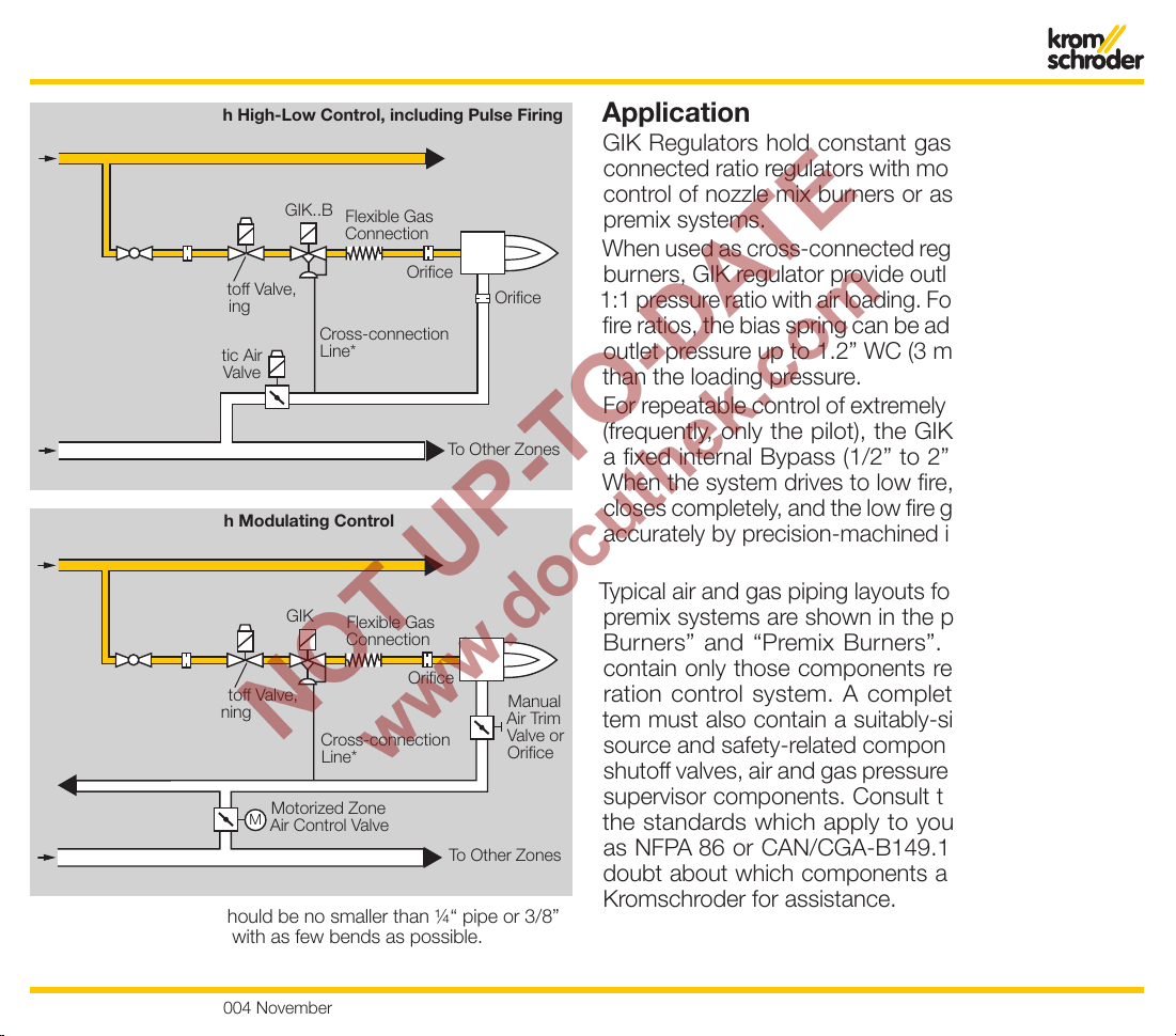
* Cross connection line should be no smaller than ¼“ pipe or 3/8”
OD tubing, as short and with as few bends as possible.
Application
GIK Regulators hold constant gas/air ratios as crossconnected ratio regulators with modulating or high-low
control of nozzle mix burners or as zero governors on
premix systems.
When used as cross-connected regulator for nozzle mix
burners, GIK regulator provide outlet gas pressure at a
1:1 pressure ratio with air loading. For leaner or richer low
fire ratios, the bias spring can be adjusted to provide an
outlet pressure up to 1.2” WC (3 mbar) higher or lower
than the loading pressure.
For repeatable control of extremely small low fire inputs
(frequently, only the pilot), the GIK..B Regulator, with
a fixed internal Bypass (1/2” to 2”), is recommended.
When the system drives to low fire, the regulator valve
closes completely, and the low fire gas flow is controlled
accurately by precision-machined internal orifice.
Typical air and gas piping layouts for nozzle-mixing and
premix systems are shown in the pictures “Nozzle Mix
Burners” and “Premix Burners”. These schematics
contain only those components related to the gas-air
ration control system. A complete combustion system must also contain a suitably-sized combustion air
source and safety-related components, such as safety
shutoff valves, air and gas pressure switches and flame
supervisor components. Consult the latest versions of
the standards which apply to your installation, such
as NFPA 86 or CAN/CGA-B149.1, for guidance. If in
doubt about which components are required, contact
Kromschroder for assistance.
Nozzle Mix Burners with High-Low Control, including Pulse Firing
Manual
Shutoff Valve
Orifice
GIK..B
Flexible Gas
Connection
Orifice
Orifice
Safety Shutoff Valve,
Slow Opening
Automatic Air
Control Valve
Cross-connection
Line*
To Other Zones
GAS
AIR
Nozzle Mix Burners with Modulating Control
Manual
Shutoff Valve
Orifice
GIK
Flexible Gas
Connection
Orifice
Manual
Air Trim
Valve or
Orifice
Safety Shutoff Valve,
Slow Opening
Motorized Zone
Air Control Valve
Cross-connection
Line*
To Other Zones
GAS
AIR
To Other Zones
Page 4
4
T-Product · GIK, GIK..B · 2004 November
Application
M
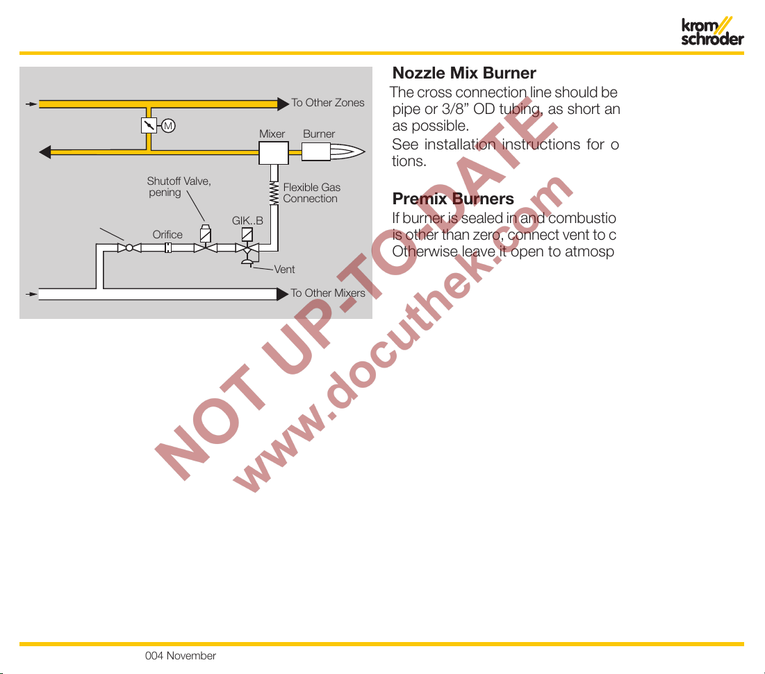
Premix Burners
Manual
Shutoff Valve
Mixer
GIK..B
Flexible Gas
Connection
Orifice
Safety Shutoff Valve,
Slow Opening
Motorized Zone
Air Control Valve
Burner
To Other Mixers
GAS
AIR
To Other Zones
Nozzle Mix Burner
The cross connection line should be no smaller than 1/4”
pipe or 3/8” OD tubing, as short and with a few bends
as possible.
See installation instructions for other recommendations.
Premix Burners
If burner is sealed in and combustion chamber pressure
is other than zero, connect vent to combustion chamber.
Otherwise leave it open to atmosphere.
Vent
Page 5
5
T-Product · GIK, GIK..B · 2004 November
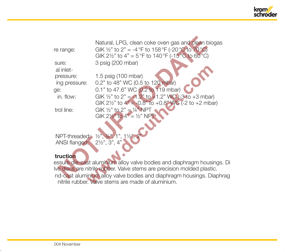
Specifications
Operating Limits
Type of gas: Natural, LPG, clean coke oven gas and clean biogas
Ambient temperature range: GIK ½” to 2” = -4 °F to 158 °F (-20 °C to 70 °C)
GIK 2½” to 4” = 5 °F to 140 °F (-15 °C to 60 °C)
Maximum inlet pressure: 3 psig (200 mbar)
Maximum operational inlet-
to-outlet differential pressure: 1.5 psig (100 mbar)
Combustion air loading pressure: 0.2” to 48” WC (0.5 to 120 mbar)
Outlet pressure range: 0.1” to 47.6” WC (0.2 to 119 mbar)
Adjusting range at min. flow: GIK ½” to 2” = -1.2” to +1.2” WC (-3 to +3 mbar)
GIK 2½” to 4” = -0.8” to +0.8” WC (-2 to +2 mbar)
Connection for Control line: GIK ½” to 2” = ¼” NPT
GIK 2½” to 4” = ½” NPT
Mechanical Data
Available pipe sizes NPT-threaded: ½”, ¾", 1”, 1½”, 2”
ANSI flanged: 2½”, 3”, 4”
Materials of Construction
GIK ½” to 2”: Pressure die-cast aluminium alloy valve bodies and diaphragm housings. Diaphragms and
valve discs are nitrile rubber. Valve stems are precision molded plastic.
GIK 2½” to 4”: Sand-cast aluminium alloy valve bodies and diaphragm housings. Diaphragms and valve discs
are nitrile rubber. Valve stems are made of aluminium.
Page 6
6
T-Product · GIK, GIK..B · 2004 November
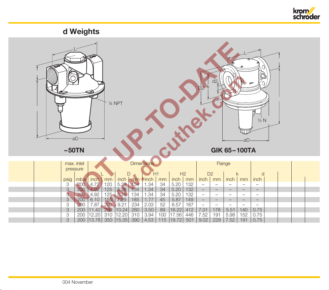
Dimensions and Weights
GIK 15 – 50TN GIK 65 – 100TA
H1
L
H2
øD
Rp
1
/4
¼ NPT
d2
k
D2
H2
øD
H1
L
Rp
1
/2
½ NPT
Type Connection max. inlet
pressure
Dimensions Flange Drilling Weight
L D H1 H2 D2 k d2 No.
psig mbar inch mm inch mm inch mm inch mm inch mm inch mm inch mm lbs kg
GIK 15TN NPT ½"
3 200 4.72 120 5.28 134 1.34 34 5.20 132 – – – – – – – 2.20 1.0
GIK 20TN NPT ¾"
3 200 4.92 125 5.28 134 1.34 34 5.20 132 – – – – – – – 2.20 1.1
GIK 25TN NPT 1"
3 200 4.92 125 5.28 134 1.34 34 5.20 132 – – – – – – – 2.20 1.1
GIK 40TN NPT 1½"
3 200 6.10 155 7.29 185 1.77 45 5.87 149 – – – – – – – 4.19 1.8
GIK 50TN NPT 2"
3 200 7.87 200 9.21 234 2.03 52 6.57 167 – – – – – – – 6.82 2.8
GIK 65TA
ANSI 2½"
3 200 11.42 290 10.24 260 3.50 89 16.22 412 7.01 178 5.51 140 0.75 19 4
26.46
12.0
GIK 80TA ANSI 3"
3 200 12.20 310 12.20 310 3.94 100 17.56 446 7.52 191 5.98 152 0.75 19 4
35.50
16.1
GIK 100TA ANSI 4"
3 200 13.78 350 15.35 390 4.53 115 19.72 501 9.02 229 7.52 191 0.75 19 8
57.33
26.0
Page 7
7
T-Product · GIK, GIK..B · 2004 November
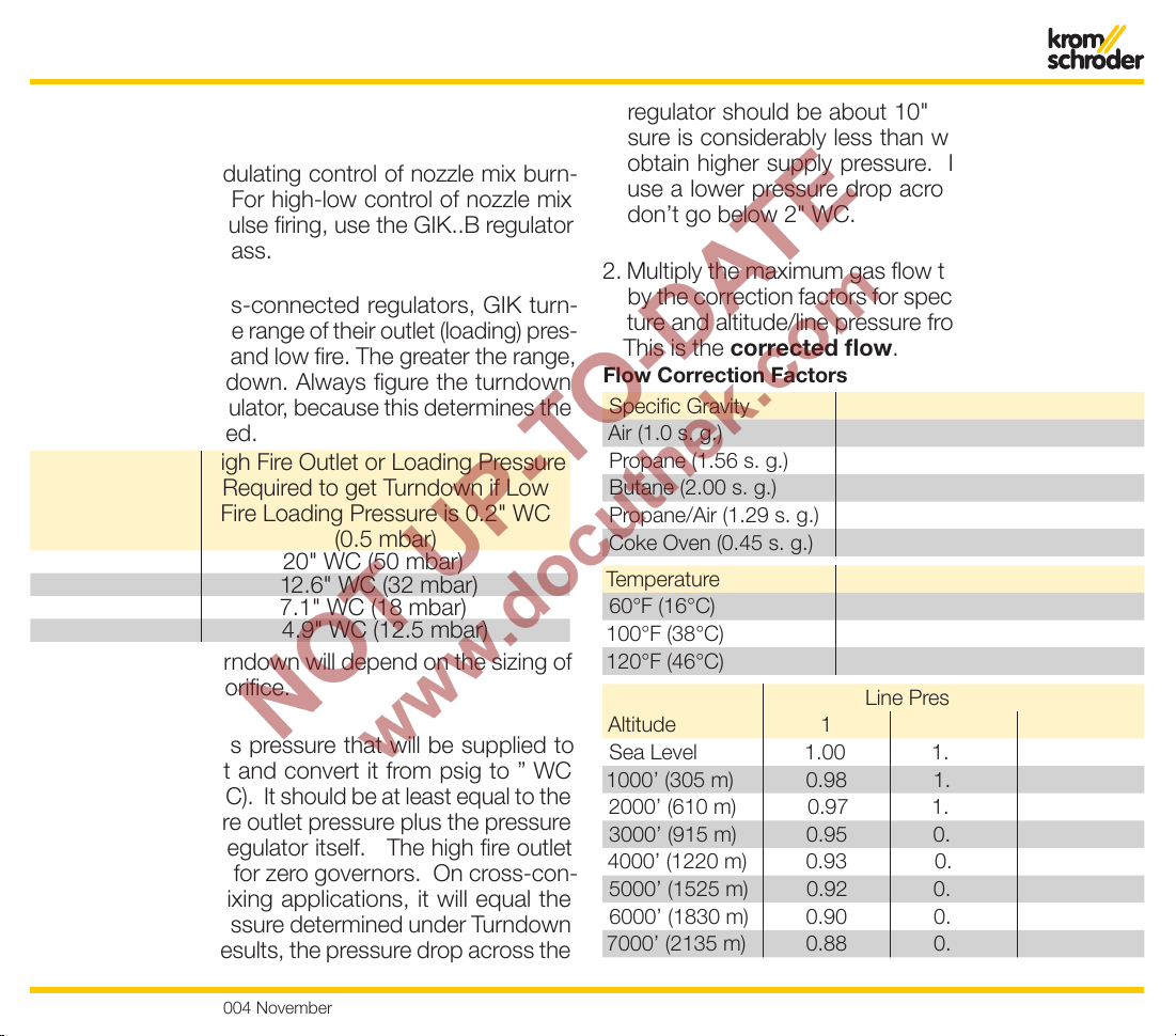
Sizing
Selection
For premix and modulating control of nozzle mix burn-
ers, select the GIK. For high-low control of nozzle mix
burners, including pulse firing, use the GIK..B regulator
with the internal bypass.
When used as cross-connected regulators, GIK turn-
down depends on the range of their outlet (loading) pres-
sures between high and low fire. The greater the range,
the greater the turndown. Always figure the turndown
before sizing the regulator, because this determines the
inlet pressure required.
Flow Turndown
Ratio
High Fire Outlet or Loading Pressure
Required to get Turndown if Low
Fire Loading Pressure is 0.2" WC
(0.5 mbar)
10 to 1 20" WC (50 mbar)
8 to 1 12.6" WC (32 mbar)
6 to 1 7.1" WC (18 mbar)
5 to 1 4.9" WC (12.5 mbar)
GIK..B Regulator turndown will depend on the sizing of
the internal bypass orifice.
1. Determine the gas pressure that will be supplied to
the regulator inlet and convert it from psig to ” WC
(psig x 27.7 = " WC). It should be at least equal to the
regulator’s high fire outlet pressure plus the pressure
drop across the regulator itself. The high fire outlet
pressure will be 0 for zero governors. On cross-con
-
nected nozzle-mixing applications, it will equal the
high fire outlet pressure determined under Turndown
above. For best results, the pressure drop across the
regulator should be about 10" WC. If the inlet pressure is considerably less than what’s needed, try to
obtain higher supply pressure. If this isn’t possible,
use a lower pressure drop across the regulator, but
don’t go below 2" WC.
2. Multiply the maximum gas flow through the regulator
by the correction factors for specific gravity, tempera
-
ture and altitude/line pressure from the tables below.
This is the corrected flow
.
Flow Correction Factors
Specific Gravity Factor
Air (1.0 s. g.) 1.27
Propane (1.56 s. g.) 1.61
Butane (2.00 s. g.) 1.83
Propane/Air (1.29 s. g.) 1.47
Coke Oven (0.45 s. g.) 0.87
Temperature Factor
60°F (16°C) 1.0
100°F (38°C) 0.96
120°F (46°C) 0.95
Line Pressure [psig]
Altitude
1 2 3
Sea Level 1.00 1.03 1.06
1000’ (305 m) 0.98 1.01 1.05
2000’ (610 m) 0.97 1.00 1.03
3000’ (915 m) 0.95 0.98 1.01
4000’ (1220 m) 0.93 0.97 1.00
5000’ (1525 m) 0.92 0.95 0.98
6000’ (1830 m) 0.90 0.94 0.97
7000’ (2135 m) 0.88 0.92 0.95
Page 8

8
T-Product · GIK, GIK..B · 2004 November
3. On the sizing chart, find where the corrected flow intersects the pressure drop from Step 1. Move down
from this point. The first regulator curve you come to
is the size to use.
Bypass Sizing
1. Correct the low fire bypass flow you want with the
same factors used to size the regulator.
2. Find this flow at the bottom of the bypass orifice sizing
chart and read up to the pressure drop that will be
available across the regulator. (At low fire, this nearly
equals the inlet pressure to the regulator, so you can
simply use the inlet pressure.)
3. Move down from this point. The first orifice curve you
come to is the size to use.
Sizing
Flow rates natural gas [m3/h]
mbar
inch WC
Pressure drop ∆p
207 9 30 40 50 60 80 100
8 10
0.2 0.3 0.4 0.6 0.8 1 2
200 700300 400 500
3 4 5 6 8 10 20
SCFH
20
30
40
4
5
6
8
10
10
20
30
40
50
60
80
100
ø
GIK: bypass plug – standard no hole
GIK..B: bypass plug – standard * GIK 15–25..B: 0.06 inch (1,5 mm)
** GIK 40–50..B: 0.197 inch (5 mm)
Bypass screw GIK..B
inch (mm) Ø
0.06 (1.5)*
0.079 (2
)
0.118 (3
)
0.157 (4
)
0.197 (5)*
*
0.236 (6
)
0.267 (7
)
0.315 (8
)
0.354 (9)
GIK 15–25..B
GIK 40–50..B
inch WC
mbar
Pressure drop ∆p
2
3
4
5
6
8
1000 2000 3000 6000 10000 20000
Flow rates natural gas [m3/h]
SCFH
Flow rate
300 500
10 20 30 40 60 80100 200 300 500 1000
10
0.8
1
20
30
40
50
2
3
4
5
6
8
10
20
30
40
50
60
80
100
GIK 15
GIK 20
GIK 25
GIK 40
GIK 50
80000
40000
2000
G
IK
65
G
IK
80
G
IK 10
0
Page 9

9
T-Product · GIK, GIK..B · 2004 November
Installation
WARNING: Improper installation, adjustment, modifi-
cation, operation or maintenance could lead to injury or
damage. All adjustments must be made by a qualified
technician.
Wiring must comply with local codes and National
Electrical Codes. To prevent the posibility of property
damage, turn off electrical power, depressurize installation, vent fluid to safe area before servicing.
• Remove thread protectors
• Observe direction of flow: arrow on housing
• Spring dome must point vertically downwards
• The housing must have clearance of ¾" from any
vertical surface. Allow access to spring adjustment
at top of housing
• Use suitable sealant, apply sparingly, only to outer
threads.
• Check for gas leaks. Apply pressure to regulator (do
not exceed name plate rating) – measured at test
point.
• Soap pipe joints and check for leaks.
Page 10

10
T-Product · GIK, GIK..B · 2004 November
5x
nominal Diameter
Air
5x
nominal Diameter
Installation
How to install the air control line
GIK ½” to 4”
The connection of the air control line must be at a
distance of 5 × nominal Diameter from other air control
elements.
Connection of the air control line
GIK ½” to 2”: NPT ¼”
GIK 2 ½” to 4”: NPT ½”
Page 11

11
T-Product · GIK, GIK..B · 2004 November
0
0
−
0
+
p
a
p
L
0
p
L
3 mm
−
+
p
a
6 mm
pa = pL± 2 mbar
p
a
=
pL± 3 mbar
Operation
To adjust the low fire position
at GIK
• Set the high fire rate using restricting orifices or adjustment
element on the burner
• At low fire position: Control pressure at least 0.2 “WC (0,5 mbar).
• Factory setting without Bypass:
outlet pressure = control line
pressure
Factory setting with Bypass:
outlet pressure = control line
pressure – 0.8“ WC (2 mbar)
➔
to keep the valve closed for constant low fire
• GIK ½" to 2" the outlet pressure
is adjustable between ± 1.2" WC
(3 mbar)
• GIK 2½" to 4" the outlet pressure
is adjustable between ± 0.8" WC
(2 mbar)
Page 12

12
T-Product · GIK, GIK..B · 2004 November
1 2 3
4 5
max. 300 mbar
GIK 15–25..B,
GIKH 25..B
GIK 40–50..B
The bypass screws
and the housing
have had markings
since November
2000. Only marked
screws may be used
with marked
housings.
Flow rates natural gas [m3/h]
mbar
inch WC
Pressure drop ∆p
207 9 30 40 50 60 80 100
8 10
0.2 0.3 0.4 0.6 0.8 1 2
200 700300 400 500
3 4 5 6 8 10 20
SCFH
20
30
40
4
5
6
8
10
10
20
30
40
50
60
80
100
ø
GIK: bypass plug – standard no hole
GIK..B: bypass plug – standard * GIK 15–25..B: 0.06 inch (1,5 mm)
** GIK 40–50..B: 0.197 inch (5 mm)
Bypass screw GIK..B
inch (mm) Ø
0.06 (1.5)*
0.079 (2
)
0.118 (3
)
0.157 (4
)
0.197 (5)*
*
0.236 (6
)
0.267 (7
)
0.315 (8
)
0.354 (9)
GIK 15–25..B
GIK 40–50..B
To adjust the low fire position at GIK..B (with
internal Bypass)
• The air control line (air control pressure) must be
less than 0.8" WC (2 mbar) at low fire position
• The bypass screw and the housings have been
marked since Nov. 2000. Only marked screws may
be used with marked housings
• The bypass orifices determines the low fire rate.
Standard:
GIK 15 to 25 (½” to 1”) = 0.059 “ (1.5 mm)
GIK 40 to 50 (1½” to 2”) = 0.20 “ (5 mm)
GIK 65 to 100 (2½” to 4”) = use external Bypass
• Enlarge the orifice if necessary (max.)
GIK 15 to 25 (½” to 1”) = 0.16 “ (4 mm)
GIK 40 to 50 (1½” to 2”) = 0.35 “ (9 mm)
Operation
Order-No. Bypass Screws
For GIK 15 to 25 (½" to 1")
Bypass screw ∅ 0.059" (1.5 mm)
03089217
Bypass screw without orifice
03089215
Bypass variable 74919806
For GIK 40 to 50 (1½" to 2")
Bypass screw ∅ 0.2" (5 mm)
03089218
Bypass screw without orifice
03089216
Bypass variable
74919821
Page 13

13
T-Product · GIK, GIK..B · 2004 November
GIK..N
GIK..A
1
1
Order No.:
03351039
Order No.:
74910853
Special Features Conversion Kit for zero Pressure
Page 14

14
T-Product · GIK, GIK..B · 2004 November
Function
The GIK has 4 basic elements that allow to operate.
These are:
1 Valve seat
A valve seat or orifice through which the gas supply will
flow. This has a disc or plug that can close against the
seat to limit the flow of gas. By moving the disc, the outlet
flow and pressure can be altered from fully open to fully
closed. The position of the disc will determine the flow
and pressure the outlet of the regulator.
2 Internal or external impulse
Usually a tube located on the regulator outlet senses the
outlet pressure. The diaphragm is linked to the valve stem.
A change in the sensed pressure above the diaphragm
causing the restricting element to alter it’s position.
3 Air control line
The air control pressure acts against the force of the
measuring element. When state of equilibrium is achieved
between the measuring element and the loading element the resulting position of the restricting element
will determine the outlet pressure. The spring is for fine
adjusting at low fire.
4 Compensating diaphragm
A secondary diaphragm is used in compensated regu
lators. This diaphragm has the same area as the valve,
so it compensates the effect of varying inlet pressures
on the valve.
Compensating
Diaphragm
Valve seat
Internal or ex
-
ternal Impuls
Air Control Line
Spring
Working
Diaphragm
Page 15

15
T-Product · GIK, GIK..B · 2004 November
GIK 15 – 50TN
GIK 65– 100TA
Order Information
GIK air/gas ratio regulator
15 – 100 (½" to 4") nominal diameter
T T-product
A ANSI-flanged
N NPT-internal thread
02 max. inlet pressure 3 psig (200 mbar)
-3 screw plug at the inlet and outlet
-5 pressure test point at the outlet
B
with drilled bypass screw
Designation Order no.
For continous control, with NPT internal thread
GIK 15TN02-5 03155176
GIK 20TN02-5 03155128
GIK 25TN02-5 03155140
GIK 40TN02-5 03155152
GIK 50TN02-5 03155164
For High/Low/Off control, with NPT internal thread
GIK 15TN02-5B 03155177
GIK 20TN02-5B 03155129
GIK 25TN02-5B 03155141
GIK 40TN02-5B 03155153
GIK 50TN02-5B 03155165
For continous control, with ANSI flange
GIK 65TA02-3 85092320
GIK 80TA02-3 85093320
GIK 100TA02-3 85094320
Page 16

16
T-Product · GIK, GIK..B · 2004 November
1
2
Trouble Shooting
Trouble Shooting is a term used to indicate a systematic
approach to locate regulator malfunction. As with installation and maintenance, successful regulator troubleshooting depends on careful analysis and planning before
taking action. Regulators are relatively simple devices
with few faults. The most common faults are:
Flow at low fire position too high?
– It sometimes happens that the flow rate at low fire
position is to high. This is due to dirt at the valve
seat or disc. These parts should be cleaned with
suitable solvent.
– Spring adjustment set too high.
Air control pressure too high?
– The maximum possible gas outlet pressure is lower
than the max. air control pressure (air impulse line).
Use a reducing fitting
(Order no. GIK 15 to 50 = 03351040)
(Order no. GIK 65 to 100 = 74910779)
Regulator is not responding?
– The working or compensating diaphragm could
be broken. Should these happen in short intervals
check the diaphragms. Always use special air dia
-
phragms for air media.
Page 17

17
T-Product · GIK, GIK..B · 2004 November
Real characteristic Curve
Ideal characteristic Curve
1:1
Gas outlet
Pressure
Air Control Pressure
Gas/Air ratio is not 1:1 at high fire
– For example:
at low fire the air control pressure is
2" WC (5 mbar),
the gas outlet pressure is also 2" WC (5 mbar)
at high fire the air pressure is 40" WC (100 mbar),
the gas outlet pressure is lower depending on the
flow rate.
– For the gas/air ratio for high fire use gas limiting orifice
valve for fine adjustments
Trouble Shooting
Page 18

18
T-Product · GIK, GIK..B · 2004 November
Maintenance
All regulators which control the systems pressure are
subject to periodic servicing by authorized personnel.
By carrying out a regular maintenance schedule, you can
prevent problems from occuring. The regulator type and
its service conditions will help you determine how often
to conduct inspections. The more severe the working
conditions, the more frequently you should examine the
regulator.
Generally, small, modern regulators can operate for
considerable periods without attention, minimizing the
need for periodic maintenance.
When a regulator is serviced, the following general pro
-
cedure should be followed.
1 Check that a shut off valve is located in the area of
the regulator.
2 Try to ensure that there is a clear working area, and
that you have somewhere to put the regulator com
-
ponents, once removed, so they will not be lost or
damaged.
3 Always use the correct tools, in the proper sizes, to
dismantle the regulator. Rough treatment can dam
-
age an otherwise useable component.
4 If available, follow the maintenance instructions issued
by the manufacturer of the regulator.
5 Make careful note of the position of each component
before removal to aid reassembly.
6 Unless the maintenance instructions say otherwise,
take off the top cover and remove the loading
spring.
7 Dismantle the regulator, removing the diaphragm(s)
and valve.
8 Clean all parts of the body and casings.
9 Check the diaphragms and replace if necessary.
10 Clean the regulator valve. If it has a rubber seat, check
and replace if necessary.
11 Examine the orifice or valve seating. Check for burrs
and replace if damaged or worn. Avoid the use of
abrasives on valve or seats.
12 Reassemble the parts in reverse order.
13 When reassembling a ring of screws or bolts, tighten
gradually and in opposing pairs.
14 Check the regulator for leakage.
15 Reset outlet pressure to the regulator.
16 Update maintenance records for the unit.
Page 19

19
T-Product · GIK, GIK..B · 2004 November
1
1
1
1
1
1
1
Spare parts
Spare parts GIK ½" to 2"
Spare part kit (1) contains the diaphragms and orings.
Type
For Gas For Air
GIK 15
03089204 03089201
GIK 20
03089204 03089201
GIK 25
03089204 03089201
GIK 40
03089205 03089202
GIK 50
03089206 03089203
Page 20

20
T-Product · GIK, GIK..B · 2004 November
1
3
2
4
5
6
7
8
Spare parts GIK 2½" to 4"
Pos. Description GIK 65
(2½")
GIK 80
(3")
GIK 100
(4")
1 O-ring 03109276 03109277 03109277
2 O-ring 03110203 03109170 03109232
3 Valve train 74960325 74960024 74960316
4 Compensating diaphragm 35454179 34328850 35442690
5 Working diaphragm 34328846 34328856 34212875
6 Safety diaphragm 74324141 74324291 74324201
7 O-ring 03109170 03109170 03109170
8 O-ring 03109159 03109159 03109159
Spare parts
Page 21

21
T-Product · GIK, GIK..B · 2004 November
Warning
Situations dangerous to personnel and property can result from the misapplication and incorrect operation of
combustion equipment.
Kromschroder advises compliance with the National Fire Protection Association standards that apply for related
equipment and Insurance Underwriters recommendation, and care of operation.
We reserve the right to make technical changes designed to improve our products without prior notice.
For current product information, visit our website at www.kromschroder.co
m.
Contact
G. Kromschröder AG
Strotheweg 1
D-49504 Lotte (Büren)
Tel.:+49 (0)5 41 / 12 14 - 0
Fax:+49 (0)5 41 / 12 14 - 370
KROMSCHRODER INC.
1595-H Georgetown Rd.
Hudson, OH 44236
Ph. 330-342-0595
Fax 330-342-0596
info@kromschroeder.com info@kromschroder.com
www.kromschroeder.co
m www.kromschroder.com
 Loading...