

Page 1

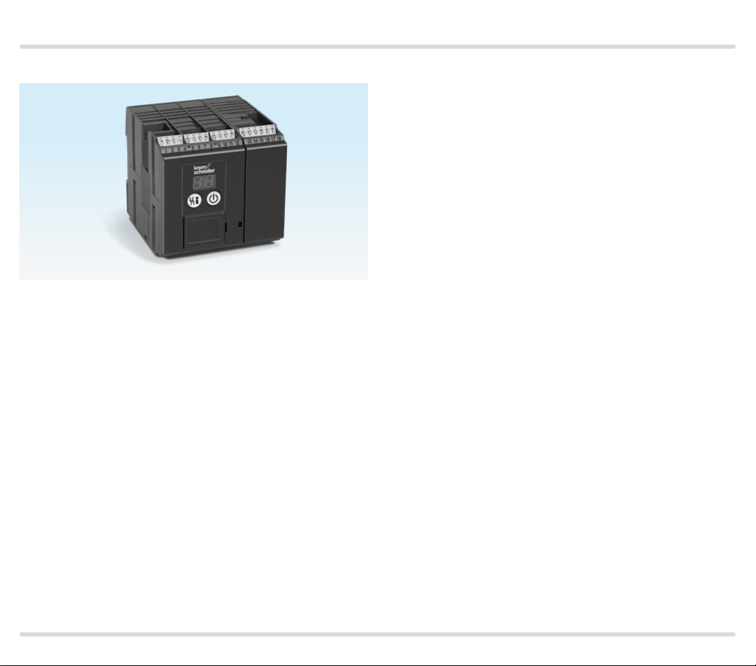
Protective system controls FCU 500, FCU 505
Technical Information · GB
6 Edition 02. 17
• For monitoring and controlling central safety functions in multiple
burner systems on industrial furnaces
• Valve proving system for a valve system leak tightness check
(optional)
• Safety temperature monitor (STM) or safety temperature limiter
(STL) (optional)
• Long service life due to replaceable power module for fail-safe
outputs
• Visualization and adaptation to the specific application via the PC
programming and diagnostic software BCSoft to simplify logistics
management
Page 2

Contents
Protective system controls FCU 500, FCU 505 ......1
Contents ............................................2
1 Application ........................................5
1.1 Application examples ..............................8
1.1.1 ON/OFF rotary impulse control .......................8
1.1.2 Modulating burner control ..........................10
1.1.3 Safety limits (LDS) for modulating burner control ...11
1.1.4 Flame control using the temperature ...............12
1.1.5 Furnace and zone control ...........................13
2 Certification ......................................14
3 Function ..........................................15
3.1 Connection diagram ..............................15
3.1.1 FCU 500 .............................................15
3.1.2 FCU 505 .............................................16
3.1.3 Assignment of connection terminals ................17
3.2 Program sequence................................19
3.2.1 FCU 50 0..F0.........................................19
3.2.2 FCU 500..F1, FCU 50 0..F2..........................20
3.2.3 FCU 505..F1, FCU 505..F2 ...........................21
3.3 Animation . . . . . . . . . . . . . . . . . . . . . . . . . . . . . . . . . . . . . . . . .22
4 Temperature monitoring......................... 23
4.1 High temperature operation with safety
temperature monitor function (STM function) .......24
4.1.1 With integrated STM ................................ 24
4.1.2 With external STM ...................................25
4.1.3 With integrated and external STM .................. 25
4.2 Maximum temperature monitoring with
(flue gas) safety temperature limiter (STL /FSTL
function) ..............................................26
4.2.1 With integrated STL/FSTL ..........................26
4.2.2 With external STL/FSTL ............................26
5 Air control ........................................27
5.1 Controlled air flow ................................28
5.2 Capacity control ..................................29
6 Furnace zone control .............................31
7 Valve proving system ............................ 33
7.1 Tightness control..................................34
7.1.1 Test instant...........................................35
7.1.2 One test volume bet ween 2 gas solenoid valves ....36
7.1.3 One test volume for system tightness...............39
7.1.4 Two test volumes for system tightness .............. 42
7.1.5 Large test volumes with reduced testing time ......46
7.2 Test period tP ..................................... 48
7.2.1 For one test volume Vp1 between 2 gas solenoid
valves ......................................................48
7.2.2 For one test volume V
7.2.3 For two test volumes for system tightness (V
V
) ........................................................49
p2
7.2.4 Extended valve opening time 1 t
7.2.5 Measurement time t
for system tightness .......48
p1
..................50
...............................53
M
L1
p1
+
7.3 Proof of closure function ..........................57
8 BCSoft........................................... 58
9 Fieldbus communication via Ethernet . . . . . . . . . . . 59
9.1 FCU and bus module BCM ...................... 60
9.2 Configuration, planning ..........................61
9.2.1 Profinet/Device master data file (GSD)..............61
9.2.2 Modbus TCP..........................................61
9.2.3 Modules/Registers for process data................62
9.2.4 Device parameters and statistics . . . . . . . . . . . . . . . . . . . 68
10 Program step/status ........................... 69
11 Fault signalling ................................. 70
12 Parameters ......................................74
12.1 Scanning the parameters........................79
12.2 Safety limits .....................................79
12.2.1 Emergency stop....................................79
12.2.2 High gas pressure protection ......................80
12.2.3 Low gas pressure protection.......................80
12.2.4 Low air pressure protection.........................81
FCU 500, FCU 505 · Edition 02.17 2
= To be continued
▼
Page 3

12.2.5 Safet y time during operation tSB ...................81
12.3 High temperature operation.....................82
12.3.1 Temperature monitoring mode ....................82
12.3.2 Thermocouple......................................83
12.3.3 Temperature difference limit value ................83
12.3.4 STM limit value (high temperature operation).....84
12.3.5 STL /FSTL limit value (system protection).........84
12.3.6 Temperature hysteresis . . . . . . . . . . . . . . . . . . . . . . . . . . . . 85
12.3.7 Pre-purge during high temperature operation ....86
12.4 Air control........................................87
12.4.1 Fan in the event of fault . . . . . . . . . . . . . . . . . . . . . . . . . . . . .87
12.4.2 Fan run-up time t
12.4.3 Fan ready for operation .............................87
12.4.4 Air monitoring during controlled air flow...........88
12.4.5 Pre-purge time t
12.4.6 Air flow monitoring during pre-purge ..............89
12.4.7 Post-purge time t
12.4.8 Air flow monitoring during post-purge.............90
12.4.9 Capacit y control.....................................91
12.4.10 Running time selection ..........................10 0
12.4.11 Running time ....................................100
12.4.12 Controller enable signal delay time t
12.4.13 Minimum enable time ...........................101
12.4.14 Burner operating signal..........................101
12.4.15 Controller enable time limit......................102
12.4.16 Capacity control (bus) ...........................103
................................87
GV
.................................88
PV
...............................89
PN
.........101
RF
12.5 Valve check ....................................108
12.5.1 Valve proving system..............................108
12.5.2 Relief valve (VPS) .................................108
12.5.3 Tightness control test volume ....................109
12.5.4 Pressure reduction V
12.5.5 Opening time relief valve V3 ......................110
12.5.6 Measurement time V
12.5.7 Measurement time V
12.5.8 Valve opening time 1 t
12.5.9 Valve opening time 2 t
...........................110
p2
...........................110
p1
and Vp2 ..................110
p1
..........................112
L1
..........................112
L2
12.6 Behaviour during start-up .....................113
12.6.1 Minimum pause time tMP .........................113
12.6.2 Switch-on delay time t
12.6.3 Filling time before start-up .......................113
..........................113
E
12.7 Manual mode .................................. 114
12.7.1 Operating time in Manual mode ..................114
12.8 Functions of terminals 51, 65, 66, 67 and 68 . 115
12.8.1 Function of terminal 51 ...........................115
12.8.2 Function of terminal 65 ...........................116
12.8.3 Function of terminal 66 ...........................116
12.8.4 Function of terminal 67 ...........................117
12.8.5 Function of terminal 68 ...........................117
12.9 Password ......................................118
12.10 Fieldbus communication ....................118
13 Selection ......................................119
13.1 Type code ......................................119
14 Project planning information ..................120
14.1 Installation.....................................120
14.2 Commissioning ................................120
14.3 Electrical connection .......................... 121
14.3.1 OCU ...............................................121
14.3.2 Safety current inputs..............................122
14.4 High temperature operation...................123
14.4.1 Safety temperature monitor (STM) ...............123
14.4.2 Safety temperature limiter (STL)..................124
14.4.3 Temperature sensors (double thermocouples) . . .124
14.4.4 Thermocouples....................................124
14.4.5 PFH
and thermocouple........................................126
value for STM/STL temperature module
D
14.5 Safety interlock output ........................ 127
14.5.1 Safety interlock output in the case of higher
power requirement .......................................127
14.5.2 BCU with power supply for valves and ignition
transformer via safety interlocks.........................128
14.6 Actuators ......................................129
14.6.1 IC 20...............................................129
14.7 Air control ......................................129
14.8 Parameter chip card ...........................130
14.9 System leak tightness check ..................130
15 Accessories.................................... 131
FCU 500, FCU 505 · Edition 02.17 3
= To be continued
▼
Page 4

15.1 BCSoft ..........................................131
15.1.1 Opto-adapter PCO 200 ...........................131
15.1.2 Bluetooth adapter PCO 300 ......................131
15.2 OCU.............................................131
15.3 Connection plug set ...........................132
15.4 Stickers for labelling ...........................132
15.5 “Changed parameters” stickers................132
16 OCU ...........................................133
16.1 Application.....................................133
16. 2 Function .......................................134
16.2.1 Manual mode......................................135
16.3 Electrical connection ..........................135
16.4 Installation.....................................136
16.5 Selection.......................................136
16.6 Technical data for OCU . . . . . . . . . . . . . . . . . . . . . . . . 136
17 BCM 500 ...................................... 137
17.1 Application ......................................137
17. 2 F unction ........................................137
17.3 Electrical connection ...........................137
17.4 Installation . . . . . . . . . . . . . . . . . . . . . . . . . . . . . . . . . . . . . 138
17. 5 S e l e c t ion .......................................138
17.6 Technical data..................................138
18 Technical data .................................139
18.1 Electrical data .................................139
18.2 Mechanical data...............................140
18.3 Environment ...................................140
18.4 FCU..H1........................................140
18.5 Dimensions ....................................140
18.6 Safety-specific characteristic values...........141
18.7 Converting units ...............................142
19 Maintenance ..................................143
20 Legend ........................................144
21 Glossary.......................................145
21.1 Safety shut-down.............................. 145
21.2 Fault lock-out..................................145
21.3 Warning signal.................................145
21.4 Timeout ........................................146
21.5 Lifting .........................................146
21.6 Diagnostic coverage DC.......................146
21.7 Operating mode ...............................146
21.8 Safe failure fraction SFF........................147
21.9 Probability of dangerous failure PFH
21.10 Mean time to dangerous failure MTTF
........147
D
.....147
d
Feedback .........................................148
Contact...........................................148
FCU 500, FCU 505 · Edition 02.17 4
= To be continued
▼
Page 5
Application
▼
1 Application
FCU with plug-in connection terminals
Protective system control FCU 500 is designed to mon-
itor and control central safety functions, e.g. gas
gas
max.
, air
, pre-purge, tightness test, high tempera-
min.
ture operation or start enable for burner control units, in
multiple burner systems on industrial furnaces. In a furnace and zone control system, the FCU 500 assumes
central functions. The FCU 505 is used to monitor local
safety functions and to control the zone capacity. If the
centrally checked safety requirements, e.g. pre-purge,
flow detector and pressure switch check, have been
met, the FCUs issue the start enable signal to the burner control units.
The FCU is optionally available with integrated safety
temperature monitor or safety temperature limiter,
integrated tightness control and with an interface for
min.
,
controlling the capacity of actuators or a frequency
converter interface.
The program status and device parameters can be read
directly from the unit. The FCU can be activated manually using the integrated Manual mode for setting and
diagnostic purposes.
Thanks to the optionally integrated valve proving sys-
tem, the valves can be checked for leaks by querying
an external gas pressure switch or it can be checked
whether the gas valve on the inlet side is closed.
Using the BCSoft program, the parameters, analysis
and diagnostic information can be read from the FCU
via the optionally available opto-adapter. All valid parameters are saved on an integrated parameter chip
card. The parameter chip card can be removed from the
old unit and inserted into a new FCU to transfer the parameters, for example when replacing the unit.
FCU 500, FCU 505 · Edition 02.17 5
Page 6

Application
The monitored outputs for the actuator and valves are
accommodated in a plug-in power module. This can
simply be replaced if necessary.
Once the plug-in power module has been removed, the param-
eter chip card and fuses are accessible.
The FCU can be installed on a DIN rail in the control
cabinet. Plug-in connection terminal strips on the FCU
make it easier to install and remove.
The external operator-control unit OCU is available as
an option for the protective system controls. The OCU
can be installed in the control cabinet door instead of
standard control units. The program status, statistics,
parameter values or fault messages can be read on
the OCU. For burner adjustment, the operating points
can be approached conveniently in Manual mode using
the operator-control unit.
Thanks to the operator-control unit OCU, display functions and
operation of the FCU can be relocated to the control cabinet
door.
The optional bus module BCM 500 makes it possible
to connect the FCU to a fieldbus interface in a Profinet
or Modbus TCP network. Networking via the fieldbus
enables multiple FCUs to be controlled and monitored
by an automation system (e.g. PLC). The bus module is
prepared for DIN rail installation. It is pushed on to the
FCU from the side.
The address for the fieldbus communication is set using three
code switches.
FCU 500, FCU 505 · Edition 02.17 6
Page 7
Application
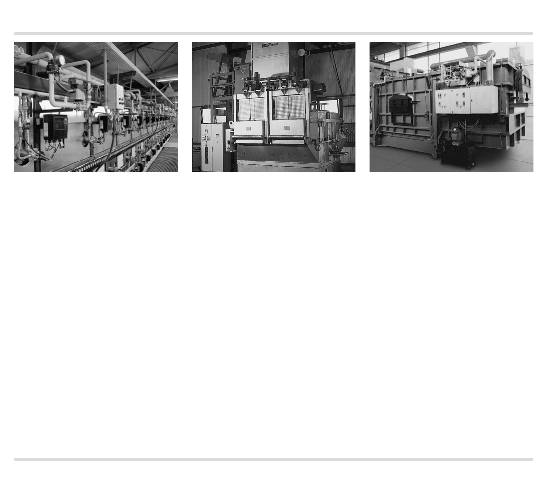
Roller hearth kiln in the ceramics
industry
Shaft melting furnace Smelting and holding furnace
FCU 500, FCU 505 · Edition 02.17 7
Page 8
Application
PZL PZH PZ
DG DG DG
DG
min
49 15 131450
46
1
ϑ
2
3
FCU 500..F0
M
DG
max
µC
STM
DL
VAS
45
pu/2
P
>750°
47 4858
minDLPurge
PZL PDZ
DG DG
VAS
VAS
BCU 460..L
BCU 460..L
VCG
VR..L
VCG
VR..L
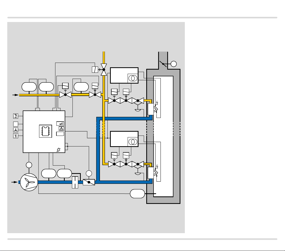
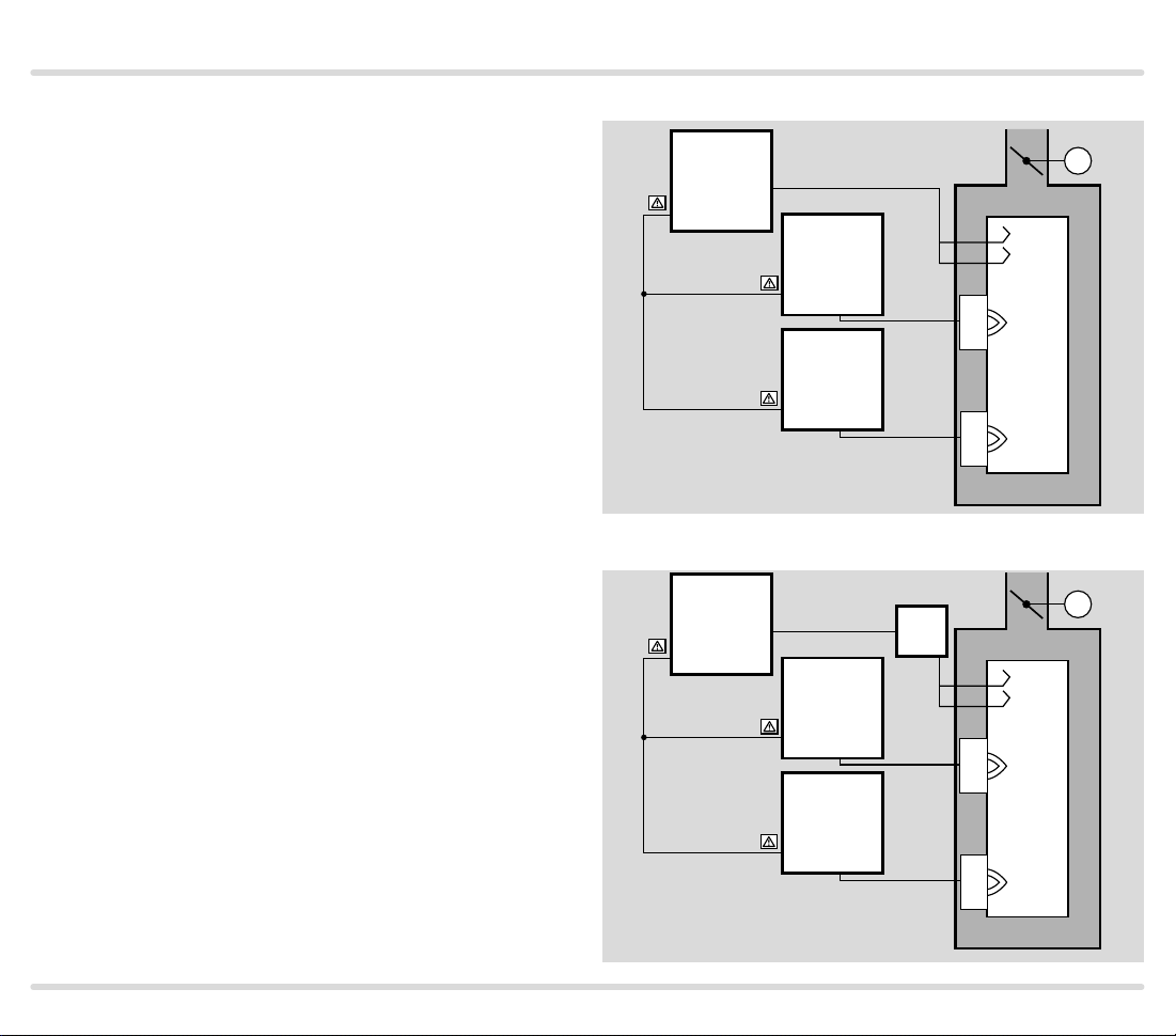
1.1 Application examples
1.1.1
ON/OFF ro tar y impul se contr ol
For processes which require a turndown of more than 10:1 and/or
those which require heavy circula-
M
TE
tion of the furnace atmosphere to
ensure a uniform temperature, e.g.
heat treatment furnaces operating
at low and medium temperatures in
the metallurgical industry.
With ON/OFF cyclic control, the
capacity supplied to the process is
controlled by means of a variable
ratio of the operating time to the
pause time. In this type of control,
the burner output pulse frequency
always maintains full momentum
and results in maximum convection
in the furnace chamber, even with
regulated heating.
The pneumatic ratio control sys-
tem controls the gas pressure on
the burner proportionally to the air
pressure and thus maintains a constant air/gas ratio. At the same time,
it acts as a low air pressure protection device.
▼
FCU 500, FCU 505 · Edition 02.17 8
Page 9
Application
PZL PZH PZ
VAS
BCU 460..L
The ignition and monitoring of the
individual burners is ensured by
burner control unit BCU 460..L.
The centrally checked safety func-
tions such as pre-purge, tightness
M
test, flow detector and pressure
switch check (gas
air
) are provided by the FCU 500.
min.
min.
, gas
max.
,
45
P
>750°
VAS
pu/2
VAS
VCG
VR..L
BCU 460..L
DG DG DG
DG
46
1
ϑ
2
3
min
49 15 131450
DG
max
µC
FCU 500..F0
47 4858
STM
DL
minDLPurge
M
PZL PDZ
DG DG
FCU 500, FCU 505 · Edition 02.17 9
VCG
VR..L
TE
Page 10
Application
PZL PZH PZ
DG DG DG
DG
min
49 15 131450
46
1
ϑ
2
3
FCU 500..F1
M
DG
µC
STM
DL
minDLPurge
VAS
max
45
P
>750°
TC
0°➔90°
53
90°➔0°
54
55
47 4858
PZL PDZ
DGDG
pu/2
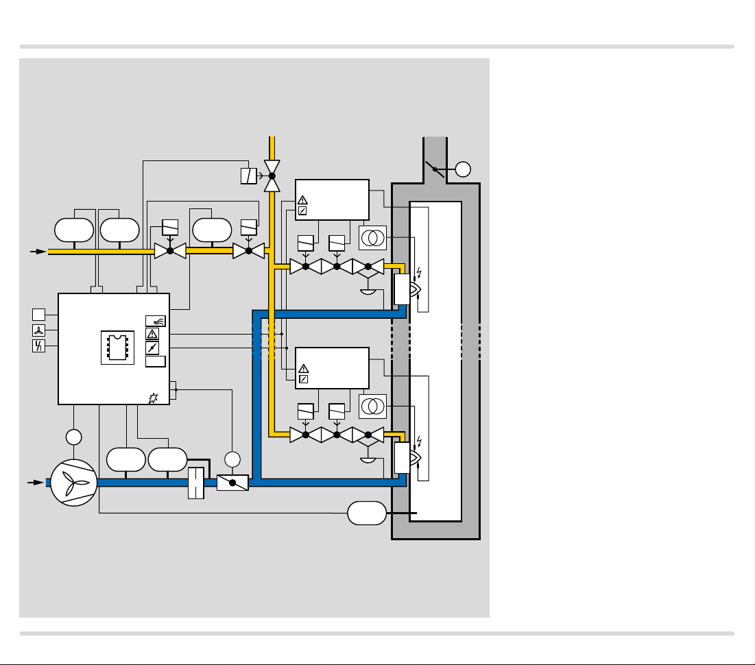
1.1.2 Modulating burner control
For processes that do not require
heavy circulation in the furnace, e.g.
aluminium smelting furnaces.
This system is suitable for process-
VAS
BCU 460..L
M
es in which infiltrated air may flow
into the furnace through switched
off burners. The capacity can be
adjusted continuously by activating
the air control valve (analogue or
VAS
VCG
3-point step signal). The pneumatic
ratio control system controls the
gas pressure proportionally to the
air pressure and thus maintains a
constant air/gas ratio. At the same
BCU 460..L
time, it acts as a low air pressure
protection device.
One burner control unit per burner
is required for ignition and monitor-
VCG
M
ing.
The centrally checked safety func-
tions such as pre-purge, setting the
TE
valve to ignition position via a butterfly valve control system, tightness test, flow detector and pressure switch check (gas
air
) are provided by the FCU 500.
min.
min.
, gas
max.
,
FCU 500, FCU 505 · Edition 02.17 10
Page 11
Application
PZL PZH PZ
DG DG DG
DG
min
49 15 131450
1
ϑ
2
3
FCU 500..F1
M
DG
µC
STM
DL
minDLPurge
VAS
max
45
P
57
16
>750°
TC
0°➔90°
53
90°➔0°
54
55
47 4858
PZL PDZ
DGDG
pu/2
1.1.3 Safety limits (LDS) for modulating burner control
The centrally checked safety func-
tions such as pre-purge, setting the
valve to ignition position via a but-
VAS
BCU 560..F0
66
M
terfly valve control system, tightness test, flow detector and pressure switch check (gas
air
) are provided by the FCU 500.
min.
min.
, gas
max.
,
The capacity can be adjusted con-
VAS
VCG
tinuously by activating the control
element (analogue or 3-point step
signal).
To ensure that the correct air vol-
ume is available for ignition (start
BCU 560..F0
66
fuel flow rate) when starting the
burners, the FCU sends the burner
start enable signal to the BCUs via
the “LDS (limits during start-up)”
output.
VCG
M
The circuit design of the safety
interlock and LDS outputs on the
FCU and the corresponding in-
TE
puts on the BCUs ensures that the
burners can only start if the safety
interlocks and the LDS output have
enabled burner start-up.
FCU 500, FCU 505 · Edition 02.17 11
Page 12
Application
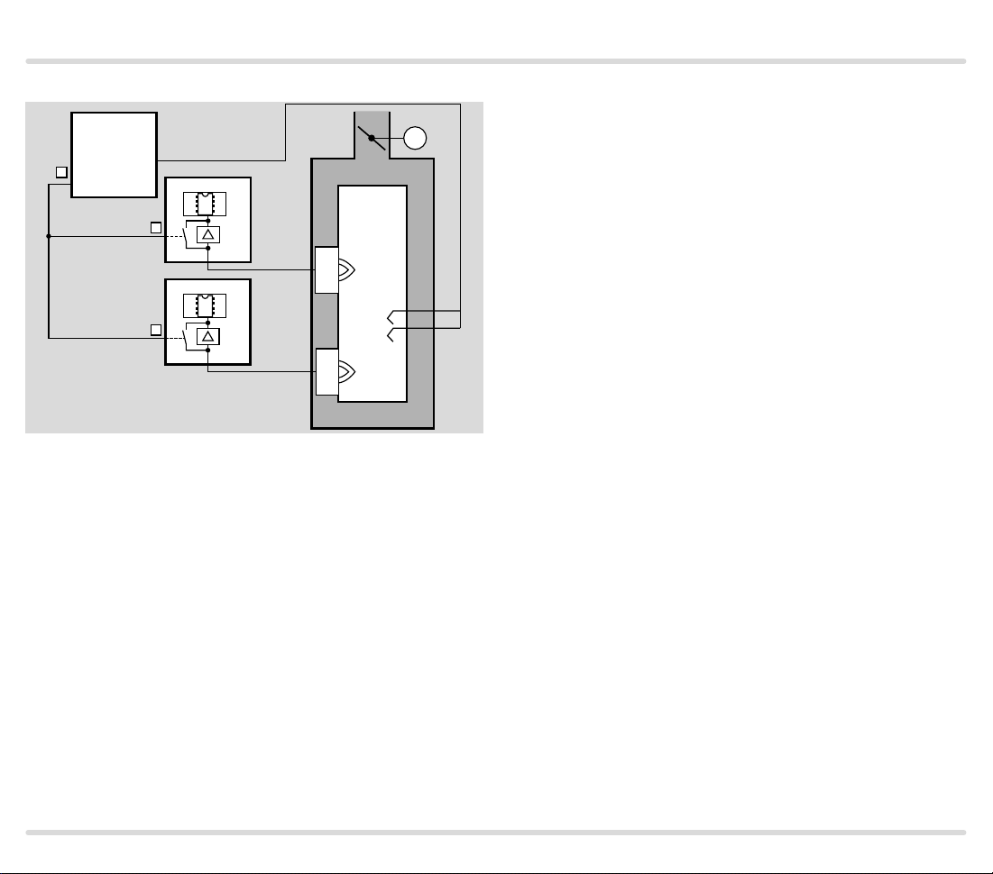
1.1.4 Flame control using the temperature
FCU 500..H1
HT
18
5-8
STM
HT
49
HT
49
BCU 56x..D
µC
5
BCU 56x..D
µC
5
M
In high temperature systems (temperature > 750°C),
the flame may be controlled indirectly via the temperature. As long as the temperature in the furnace chamber
is below 750°C, the flame must be controlled by conventional methods.
If the temperature in the furnace chamber rises above
the spontaneous ignition temperature of the gas/air
mixture (> 750°C), the FCU signals to the burner control
units via the fail-safe HT output that the furnace system is in High temperature mode (HT). When the HT input is activated, the burner control units switch to High
temperature mode. They operate without evaluation of
the flame signal and their internal flame control system
is non-functional.
If the furnace temperature falls below the spontaneous
ignition temperature (< 750°C), the FCU disconnects
the HT output from the electrical power supply. There
is no active signal at the HT inputs of the burner control
units. The flame signals are monitored once again by
the UV sensor or flame rod.
In the event of a fault in a temperature monitoring component (e.g. sensor discontinuity, sensor short-circuit)
or in the event of a mains failure, the flame control task
is transferred to the burner control units.
FCU 500, FCU 505 · Edition 02.17 12
Page 13
Application
PZL PZH PZ
66
46
4
FCU 505..F1
+24V
L1
49 15 131450
1
2
3
FCU 500..F0
µC
4758 48
45
67
57
17
P
M
PZL PDZ
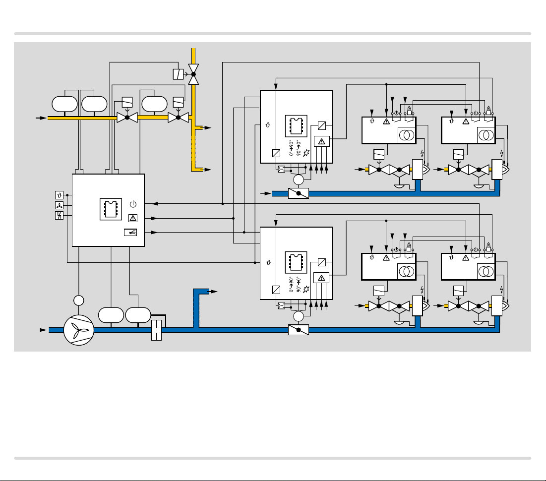
1.1.5 Furnace and zone control
The FCU 500 (furnace FCU) performs central tasks
such as checking the safety interlocks, fan control, system leak tightness check and pre-purge.
It signals to the FCU 505 in the zones that the butterfly
valves can be moved to the purge position. Signals are
1
µC
54 55
53
BCU
V1
V1
BCU
M
L1
BCU
+24V
BCU
V1
V1
66
46
1
4
FCU 505..F1
µC
54 55
53
M
sent to the butterfly valves by the FCU 505. The butterfly valves move into position. A signal is sent to the
FCU 505 via their safety interlock input that the central
FCU 500 has issued the enable signal for the burners.
FCU 500, FCU 505 · Edition 02.17 13
Page 14

Certification
2 Certification
Certificates – see Docuthek.
Certified pursuant to SIL
For systems up to SIL 3 pursuant to EN 61508.
Pursuant to EN ISO 138491:2006, Table 4, the FCU
can be used up to PL e.
EU certified pursuant to
– Gas Appliances Directive (2009/142/EC) in conjunc-
tion with EN 298, EN 1643
Meets the requirements of the
– Low Voltage Directive (2006/95/EC),
– EMC Directive (2004/108/EC).
FM approved
ANSI/CSA approved
American National Standards Institute/Canadian
Standards Association –ANSI Z21.20/CSA C22.2,
No. 199
www.csagroup.org –Class number: 333501 (natural
gas, propane), 333581 (natural gas, LPG).
Eurasian Customs Union
The product FCU 500 meets the technical specifica-
tions of the Eurasian Customs Union.
Factory Mutual Research Class: 7610 “Combustion Safe-
guards and Flame Sensing Systems”. Suitable for applications pursuant to NFPA 86. www.approvalguide.com
FCU 500, FCU 505 · Edition 02.17 14
Page 15
Function
3 Function
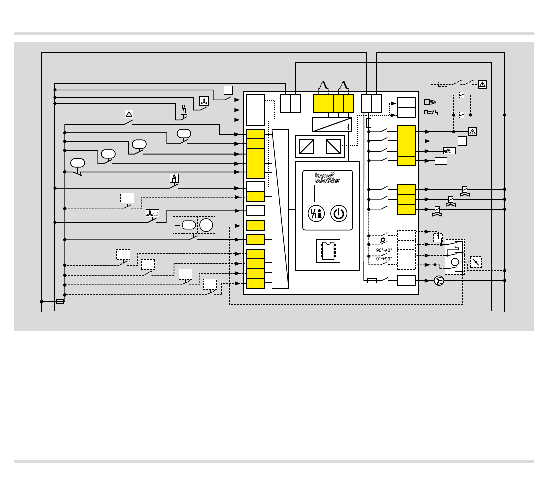
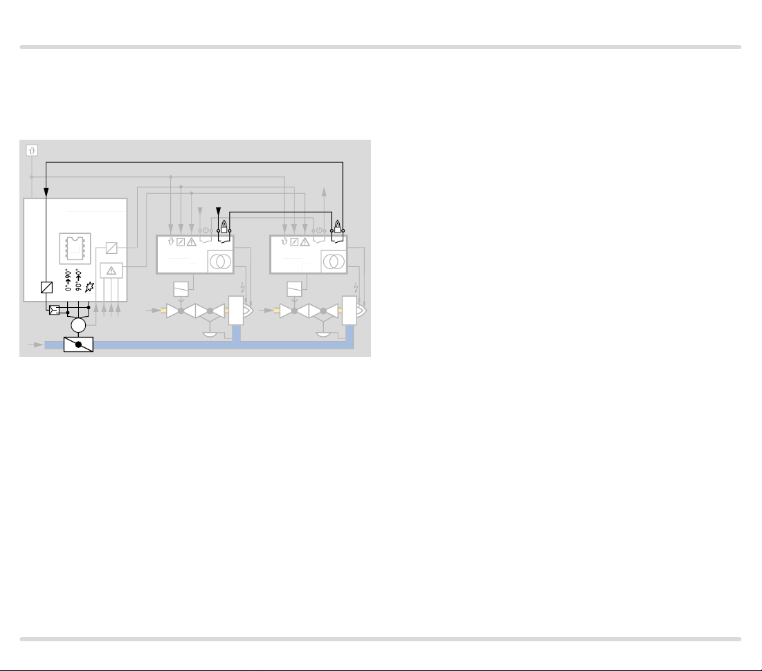
3.1 Connection diagram
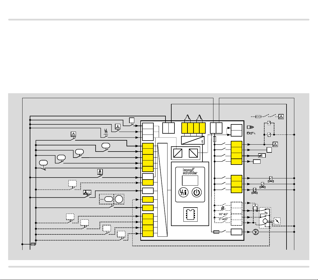
3.1.1 FCU 500
Detailed connection diagrams for actuators and fre-
quency converters, see from page 91 (Capacity control)
ϑ
PZL
PZL
Air
min
p
u
PZL
GZL
2
PZH
PZH
Gas
Air
PDZ
Gas
P72
P72
PDZ
min
PZL
PZL
max
Electrical connection, see page 120 (Project planning
information)
Explanation of symbols, see page 144 (Legend)
1 2 3 46 47 48 49 50 4 67 52 45 51 65 66 68
62 61 5 6 7 8 11
44
STM/
STL
+ - + -
24V
DC
88
12
3,15AT
41 4216
17 18 57
13 14 1553
I
N
× 0.6
LDS
k11 k21
K2
K1
HT
P
V2
V1
V3
µC
FCU 505
FCU 500
5AT
54 55 56
58
M
0 V
N
L1
+24 V
0.6 × I
P69
P70
P70
P71
P71
P73
P73
N
FCU 500, FCU 505 · Edition 02.17 15
Page 16
Function
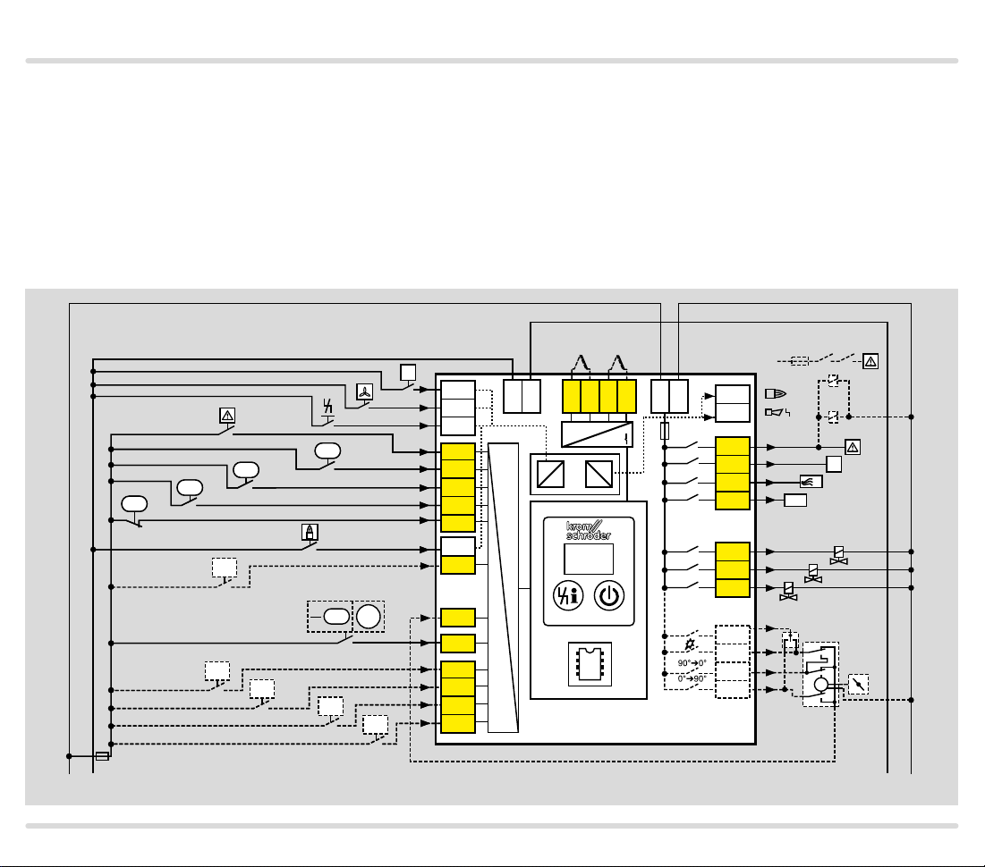
3.1.2 FCU 505
Detailed connection diagrams for actuators and fre-
quency converters, see from page 91 (Capacity control)
Electrical connection, see page 120 (Project planning
information)
Explanation of symbols, see page 144 (Legend)
L1
+24 V
PZH
PZH
0.6 × I
Gas
N
STM/
STL
ϑ
1 2 3 46 47 48 49 50 4 67 52 45 51 65 66 68
62 61 5 6 7 8 11
PZL
PZL
Air
Air
PDZ
Gas
P72
P72
PDZ
min
PZL
PZL
max
min
+ - + -
24V
DC
88
12
3,15AT
41 4216
17 18 57
13 14 1553
p
u
PZL
GZL
2
P69
P70
P70
P71
P71
P73
P73
µC
FCU 505
54 55 56
I
N
× 0.6
LDS
V1
k11 k21
K2
K1
HT
P
V2
M
V3
0 V
N
FCU 500, FCU 505 · Edition 02.17 16
Page 17

Function
3.1.3 Assignment of connection terminals
Terminal Type Designation Function
1
2 Controlled air flow
24 V DC input
3 Remote reset Input for ex ternal signal (button) to reset the unit after a fault lock-out
4 Operating signal
5, 6
and
7, 8
11, 12 V AC input Supply voltage
13
14 Gas valve V2 Connection of phase for gas valve V2
15 Gas valve V3 Connection of phase for gas valve V3
57 Safety interlocks (limits) Safety enable signal to the burner control units
16 Safety limits (limits during start-up)
17 Purge Signal to FCU 505 or burner control units to inform them that purge is in process
18 High temperature operation Enable signal from the FCU indicating that the furnace system is in High temperature mode
41
42 Operating signal Operation signalling output, 24 V DC, max. 0.1 A
44 24 V DC input Fan ready for operation Feedback signal from fan indicating readiness for operation, see Parameter 31
Double
thermocouple
Safety circuit output
24 V DC output
Start-up signal Signal applied: FCU start; no signal: FCU stop
Signal applied: fan is started to supply air to the combustion chamber for cooling, for
example. Only functional in standby. The function is deactivated as soon as a signal is
received at terminal 1 (FCU start).
Signal from the burner control units to inform the FCU that a sufficient number of burners is
available for temperature control
Safety temperature monitor and/or
safety temperature limiter
Gas valve V1 Connection of phase for gas valve V1
Fault Fault signalling output, 24 V DC, max. 0.1 A
Monitor the spontaneous ignition temperature of the gas/air mixture in High temperature
mode and/or the maximum furnace or flue gas temperature using the integrated
temperature module of the FCU..H1
Voltage to operate the FCU,
11 = phase (L1), 12 = neutral conductor (N)
To ensure that the correct air volume is available for ignition (start fuel flow rate) when
starting the burners, the FCU sends the burner start enable signal to the burner control
units via this output.
▼
FCU 500, FCU 505 · Edition 02.17 17
Page 18

Function
Terminal Type Designation Function
45
46 Controller enable/emergency stop
47 Minimum air pressure
48 Minimum air flow
49 Minimum gas pressure Connection for pressure switch to monitor the minimum gas pres sure, see Parameter 13
50 Maximum gas pressure Connection for pressure switch to monitor the maximum gas pressure, see Parameter 12
51, 65,
66, 67,
68
52
53, 54,
55, 56
58 Fan
Safety circuit input
V AC output
Valve proving system
Programmable inputs
Feedback from actuator/frequency
converter
Capacity control
Connection for the sensor of the valve proving system (tightness control pressure switch or
POC switch for checking the closed position).
Connection for higher-level safety devices and interlocks (e.g. emergency stop, safety
temperature monitor), see Parameter 10
Connection for pressure switch to monitor the minimum air pressure, see
Parameter 15
Connection for a sensor to monitor the minimum air flow during pre-purge or post-purge,
see Parameters 35, 38
The terminals can be assigned a function using parameters. To do so, logical AND gatings
with terminals 46, 47, 48, 49 or 50 are possible.
Connection for the position feedback signal from the actuator/frequency converter
Connection for capacity control using an actuator or frequency converter,
see Parameter 40 to 47
Connection for fan control. Alternatively, this output can be used to activate a valve to check
the function of the air pres sure switch.
FCU 500, FCU 505 · Edition 02.17 18
Page 19

Function
3.2 Program sequence
3.2.1 FCU 500..F0
Example of application, see page 8 (ON/OFF rotary
impulse control)
Switch on the FCU
▼
In the event of fault signal: reset
▼
00
H0
Switch-on delay time t
01
1
P1
08
Enable signal to burner control units for the burner start via the “safety
Start-up position/standby
▼
Start-up with ϑ signal
▼
running (parameter 63)
Safety interlocks check
Fan run-up time tGV running (parameter 30)
Pre-purge time tPV running (parameter 34)
Tightne ss test (if equipped with TC)
Gas enable via valves V1 and V2
E
▼
Pre-purge starts
▼
Air flow monitoring
▼
▼
interlock” output
▼
Operation
FCU 500, FCU 505 · Edition 02.17 19
Page 20

Function
3.2.2 FCU 500..F1, FCU 500..F2
Example of application, see page 10 (Modulating
burner control)
Switch on the FCU
▼
In the event of fault signal: reset
▼
00
H0
01
A
P1
A
H7
H8
08
Switch-on delay time t
Actuator moves to the position for maximum capacity
1
Actuator moves to the position for ignition capacity
Enable signal to burner control units for the burner start via the
Controller enabler signal delay time t
Start-up position/standby
▼
Start-up with ϑ signal
▼
running (parameter 63)
Safety interlocks check
E
▼
Fan run-up time t
running (parameter 30)
GV
Pre-purge starts
▼
▼
Air flow monitoring
▼
Pre-purge time t
Tightne ss test (if equipped with TC)
running (parameter 34)
PV
▼
▼
Gas enable via valves V1 and V2
“safety interlock” output
▼
▼
Operation/controller enable
running
RF
FCU 500, FCU 505 · Edition 02.17 20
Page 21

Function
3.2.3 FCU 505..F1, FCU 505..F2
Example of application, see page 13 (Furnace and
zone control)
Switch on the FCU
▼
In the event of fault signal: reset
▼
00
H0
01
A
P1
H8
08
Switch-on delay time t
Actuator moves to the position for maximum capacity
A
Actuator moves to the position for ignition capacity
Controller enabler signal delay time t
Start-up position/standby
▼
Start-up with ϑ signal
▼
running (parameter 63)
Safety interlocks check
E
▼
Fan run-up time t
running (parameter 30)
GV
Pre-purge starts
▼
▼
FCU 500 pre-purge time t
Tightne ss test (if equipped with TC)
▼
▼
▼
Operation/controller enable
running
PV
running
RF
FCU 500, FCU 505 · Edition 02.17 21
Page 22

Function
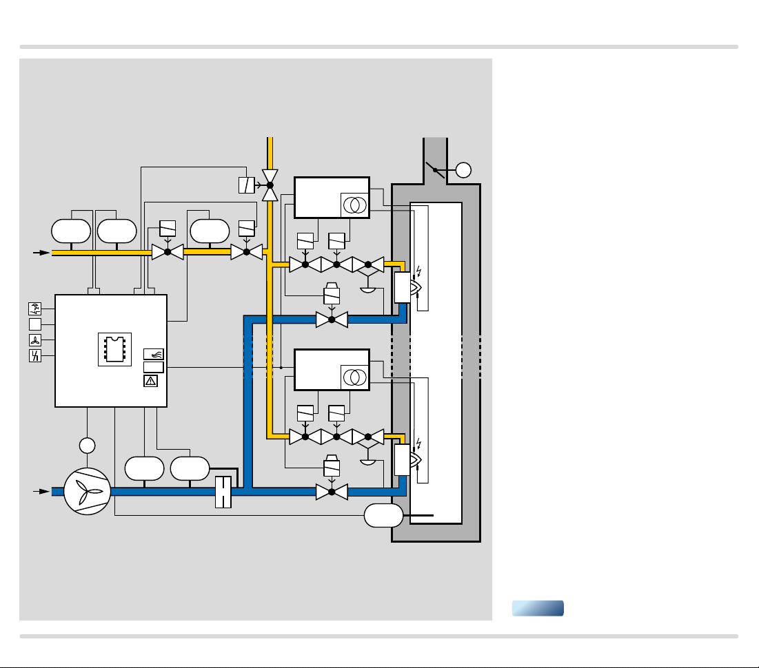
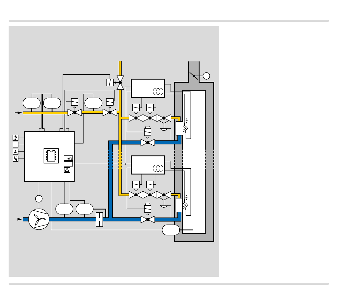
3.3 Animation
The interactive animation shows the function of the
protective system control FCU 500.
Click on the picture. The animation can be controlled
using the control bar at the bottom of the window (as
on a DVD player).
To play the animation, you will need Adobe Reader 9 or a
FCU 500, FCU 505 · Edition 02.17 22
newer version. If you do not have Adobe Reader on your
system, you can download it from the Internet. Go to
ww w.adobe.com, click on “Adobe Reader” at the bottom
of the page and follow the instructions.
If the animation does not start to play, you can download it from the document library (www.docuthek.com)
as an independent application.
Page 23

Temperature monitoring
4 Temperature monitoring
The FCU..H1 is fitted with an integrated temperature
module.
This module can be used as a safety temperature moni-
tor (STM) to monitor the spontaneous ignition temperature of the gas/air mixture or as a safety temperature
limiter (STL) to monitor the maximum furnace/flue gas
temperature. Double thermocouples are connected to
the temperature module to measure the temperature.
The functions STM and STL can also be combined. In
this case, the connected double thermocouple must reliably detect whether the spontaneous ignition temperature (> 750°C) has been exceeded and also whether
the maximum permitted furnace temperature has been
exceeded.
The safety temperature monitor and safety temperature
limiter functions can be adjusted to the requirements of
the system using parameters 20, 22, 23, 24 and 25, see
page 82 (High temperature operation).
FCU 500, FCU 505 · Edition 02.17 23
Page 24
Temperature monitoring
4.1 High temperature operation with safety
temperature monitor function (STM function)
As soon as the temperature in the furnace chamber
is above the spontaneous ignition temperature of the
gas/air mixture (> 750°C), the FCU signals to the downstream burner control units via the fail-safe HT output
that the furnace system is in High temperature mode
(HT). When the HT input is activated, the burner control
units switch to High temperature mode. They operate
without evaluating the flame signal and their internal
flame control is non-functional.
If the furnace temperature falls below the spontaneous
ignition temperature (< 750°C), the FCU disconnects
the HT output from the electrical power supply. As soon
as the signal to the HT inputs of the burner control
units is no longer present, the flame signals are once
again monitored by a UV sensor or flame rod.
In the event of a fault in a temperature monitoring component (e.g. sensor discontinuity, sensor short-circuit)
or in the event of a mains failure, the flame control task
is transferred to the burner control units.
Either the temperature module integrated in the FCU..
H1 or an external safety temperature monitor (STM)
can be used for High temperature mode. Pre-purge
can be disabled for both versions in High temperature
mode, see page 86 (Pre-purge during high temperature operation).
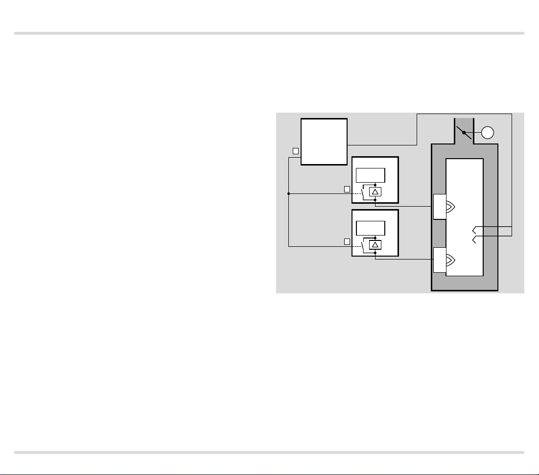
4.1.1 With integrated STM
The integrated temperature module (STM) can be used
for high temperature operation. Pre-purge can be disabled in High temperature mode, see page 86 (Prepurge during high temperature operation).
FCU 50x..H1
HT
18
5-8
STM
HT
6
HT
6
BCU 4xx..D
µC
9
BCU 4xx..D
µC
9
M
FCU 500, FCU 505 · Edition 02.17 24
Page 25
Temperature monitoring
M
BCU 4xx..D
µC
9
BCU 4xx..D
µC
9
HT
18
6
6
HT
HT
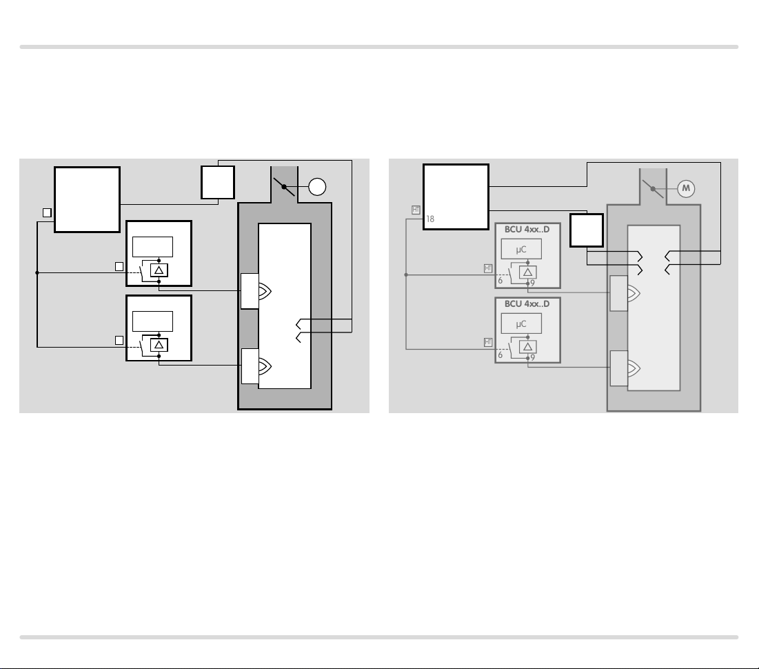
4.1.2 With external STM
An external safety temperature monitor (STM) can be
used for high temperature operation. Pre-purge can
be disabled in High temperature mode, see page 86
(Pre-purge during high temperature operation).
FCU 50x..H0
FCU 50x..H1
HT
18
66
BCU 4xx..D
µC
HT
6
9
BCU 4xx..D
µC
HT
6
9
STM
M
4.1.3 With integrated and external STM
The integrated temperature module can also be used in
conjunction with an external safety temperature monitor (STM). The spontaneous ignition temperature can
then be monitored at two different points in the furnace.
FCU 50x..H1
5-8
STM
66
STM
FCU 500, FCU 505 · Edition 02.17 25
Page 26
Temperature monitoring
4.2 Maximum temperature monitoring with
(flue gas) safety temperature limiter (STL/FSTL
function)
As soon as the maximum permitted temperature limit
is reached in the furnace or in the flue gas or an error
occurs on the monitoring equipment within the permitted temperature range (e.g. sensor discontinuity, sensor
short-circuit), the FCU will perform a fault lock-out. The
safety interlock output will no longer be set.
The temperature module integrated in the FCU..H1 or
an external safety temperature limiter (STL) can be
used for this function.
4.2.1 With integrated STL/FSTL
FCU 50x..H1
5-8
57
STL
BCU 4xx..D
5
BCU 4xx..D
BCU 4xx..D
5
9
9
9
4.2.2 With external STL/FSTL
FCU 50x..H0
FCU 50x..H1
57
46
BCU 4xx..D
STL
M
M
5
9
BCU 4xx..D
BCU 4xx..D
5
9
9
FCU 500, FCU 505 · Edition 02.17 26
Page 27
Air control
M
PZL PZH PZ
PZL PDZ
TE
BCU 580..F3
FCU 500..F0
µC
P
DG DG DG
VAS
VAS
VAGVAS
VAS
VR..L
VR..L
DG DG
DG
minDGmax
49 15 131450
45
47 4858
>750°
pu/2
ϑ
1
46
2
3
DL
minDLPurge
BCU 580..F3
VAGVAS
VAS
M
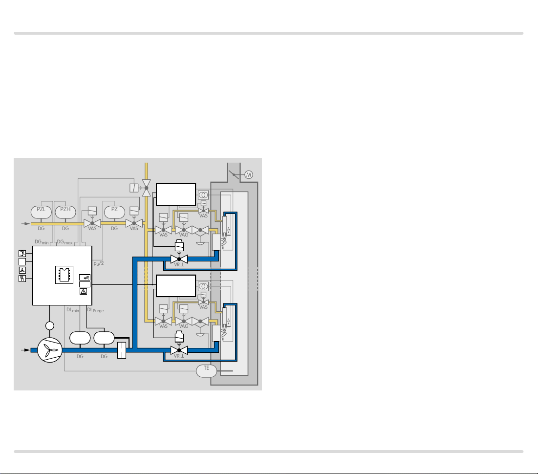
5 Air control
Acting as the furnace protective system, the FCU 500
assumes the task of central air control on a furnace. It
controls and monitors the required air volume for startup, during operation and after the furnace has been
shut down. The fan is activated by the FCU for this purpose. The static air pressure and the air volume for prepurge can be monitored by pressure switches.
VAS
BCU 580..F3
49 15 131450
46
1
ϑ
2
3
FCU 500..F0
M
µC
P
>750°
47 4858
STM
DL
minDLPurge
PZL PDZ
DG DG
45
VR..L
BCU 580..F3
VR..L
The capacity control function provided by the FCU 500..
F1/F2 and FCU 505..F1/F2 allows an additional central actuator or a frequency-controlled fan to be controlled and monitored. While the furnace is starting up,
the capacity control system controls and monitors the
required air volumes for purging and for starting the
burners. During operation, the FCU enables the external temperature control system for capacity control.
FCU 500, FCU 505 · Edition 02.17 27
Page 28
Air control
ϑ
PZL
PZL
Air
min
p
u
PZL
GZL
2
P71
P71
P73
P73
L1
+24 V
PZH
PZH
0.6 × I
Gas
N
Air
PDZ
Gas
P69
P72
P72
PDZ
min
P70
P70
PZL
PZL
max
5.1 Controlled air flow
On FCU 500, actuation of the input at terminal 2 acti-
vates the controlled air flow function. The fan (terminal 58) is started in standby (with no start-up signal).
Air is fed to the combustion chamber, e.g. for cooling.
1 2 3 46 47 48 49 50 4 67 52 45 51 65 66 68
62 61 5 6 7 8 11
44
STM/
STL
+ - + -
24V
DC
88
µC
FCU 505
FCU 500
5AT
12
3,15AT
41 4216
17 18 57
13 14 1553
54 55 56
58
I
N
× 0.6
LDS
k11 k21
K2
K1
HT
P
V3
V2
V1
M
The FCU starts the fan depending on the functions
defined using parameters, see also page 81 (Low air
pressure protection), page 88 (Air monitoring during
controlled air flow) and page 89 (Air flow monitoring
during pre-purge).
The controlled air flow function is no longer performed
once the start-up signal has been received at terminal 1.
0 V
N
FCU 500, FCU 505 · Edition 02.17 28
Page 29
Air control
CU
V1
CU
V1
µC
5455
53
1
6
(
)
V
M
1
7
▼
5.2 Capacity control
As soon as a start-up signal has been received by the
FCU..F1/F2 (terminal 1), the fan of an FCU 500..F1/F2
is started via terminal 58 after the switch-on delay time
has elapsed. The air volume for pre-purge is requested
via the outputs for central capacity control (terminals
53 to 56). Air flow monitoring (terminal 48) starts. The
pre-purge time starts if there is adequate air flow.
After the elapse of the pre-purge time, the air volume
for ignition is requested. After the program has ended
(limits during start-up, pre-purge and also tightness
test for FCU..C1), the gas enable signal is issued via the
valve outputs V1 (terminal 13) and V2 (terminal 14) and
the burner start enable signal is issued to the burner
control units via the “safety interlock” output (terminal 57).
The correct air volume for ignition (start fuel flow rate)
must be available for each burner start, restart or startup attempt. To this end, the FCU sends the burner start
enable signal to the BCUs via the “LDS (limits during
start-up)” output.
A corresponding circuit design between the FCU and
the BCUs ensures that the burners can only start if the
safety interlocks and the LDS output are active.
7
BCU..F0
+24
4
FCU 500..F1
M
6
16
57
5
1
B
B
FCU 500, FCU 505 · Edition 02.17 29
Page 30
Air control
CU
V
CU
V
µC
5455
53
1
6
(
)
V
M
After the burner operating signal from the burner con-
trol units has been received, the FCU enables the control system for operation. For pertinent parameter settings, see page 101 (Burner operating signal).
7
BCU..F0
+24
+24V
4
4
FCU 500..F1
1
B
1
54 55
53
B
1
M
Depending on parameter 40, actuators IC 20 and IC 40,
an actuator with an RBW interface or a fan controlled
by a frequency converter can be actuated via the outputs for central capacity control, see page 91 (Capacity control).
FCU 500, FCU 505 · Edition 02.17 30
Page 31

Furnace zone control
▼
PZL PZH PZ
66
46
4
FCU 505..F1
+24V
L1
49 15 131450
1
2
3
FCU 500..F0
µC
4758 48
45
67
57
17
P
M
PZL PDZ
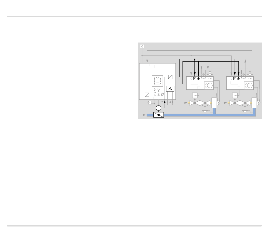
6 Furnace zone control
For furnace zone control, one FCU 500 is used to
control the furnace and several FCU 505 are used to
control the individual modulating zones (FCU 505..F1
or FCU 505..F2). When connecting several FCUs in a
circuit, a hierarchical operating structure is applied.
1
µC
54 55
53
BCU
V1
V1
BCU
M
L1
66
46
1
4
FCU 505..F1
µC
54 55
53
BCU
+24V
BCU
V1
V1
M
The furnace FCU (FCU 500) performs central tasks
such as checking the central safety functions, fan control, system leak tightness check and pre-purge.
FCU 500, FCU 505 · Edition 02.17 31
Page 32

Furnace zone control
The zone FCUs (FCU 505) control the zone capacity.
After checking the safety interlocks (after expiry of the
switch-on delay time) and when the fan run-up time
is started, the furnace FCU signals to the zone FCUs
via the input at terminal 66 that they should move
the actuators to purge position. After the purge (and
the tightness test if applicable) has been ended, the
furnace FCU signals to the zone FCUs via the input at
terminal 46 that burner start is enabled. When they
receive this signal, the zone FCUs move the valves to
ignition position for starting the burners and then issue
the enable signal to the burner control units to start the
burners.
FCU 500, FCU 505 · Edition 02.17 32
Page 33

Valve proving system
7 Valve proving system
The FCU..C1 is fitted with an integrated valve proving
system. This allows the tightness of two or more gas
solenoid valves and the pipework to be checked, see
page 34 (Tightness control). Alternatively, the closed
position of a gas solenoid valve can be checked using a
POC switch, see page 57 (Proof of closure function).
Once the test has been carried out successfully, the
furnace is enabled for start-up.
The tightness control function satisfies the require-
ments of EN 1643 (Valve proving systems for automatic shut-off valves for gas burners and gas appliances).
By checking the closed position using the proof of clo-
sure function, the FCU complies with the requirements
of NFPA 85 (Boiler and Combustion Systems Hazards
Code) and NFPA 86 (Standard for Ovens and Furnaces).
FCU 500, FCU 505 · Edition 02.17 33
Page 34

Valve proving system
7.1 Tightness control
The aim of the tightness control is to identify an in-
admissible leak on one of the gas solenoid valves
and to prevent burner start. European standards
EN 7462 and EN 676 stipulate tightness controls for
capacities over 1200 kW (NFPA 86: from 117 kW or
400,000 Btu/h).
The FCU offers several ways of testing tightness:
1. Between 2 gas solenoid valves with one test volume
(parameter 53 = 1):
p
u
V1
p
u
2. The system tightness of a complete gas inlet section
with one test volume and pressure reduction using a
relief valve (parameter 53 = 2):
V2
2
PZ
V
p1
3. The system tightness of a complete gas inlet section
with two test volumes and pressure reduction using a
relief valve (parameter 53 = 3):
DG
V3
p
u
V
p1
V1
V2
PZ
p
u
2
V
V3
PZ
p2
The valves and the pipework between the valves are
tested.
V3
V1
V
p1
p
u
FCU 500, FCU 505 · Edition 02.17 34
PZ
p
u
2
Page 35

Valve proving system
7.1.1 Test instant
Depending on the parameter setting, the tightness
control checks the tightness of the pipework and the
gas solenoid valves before each start-up and/or after
each shut-down of a furnace system, see page 108
(Valve proving system).
The gas line is always safeguarded by a gas solenoid
valve during this check.
Before furnace start-up
P1HO00 H7 H8
ϑ
1
TC Test
13
1
14
2
57
42
t
PVtRF
The FCU starts testing the tightness of the gas solenoid
valves and pipework between the valves parallel to the
pre-purge time. The gas line is always safeguarded by a
gas solenoid valve during this check. When pre-purge
is finished and the tightness has been checked successfully, the safety valves for operating the system are
opened after the safety interlocks have been enabled.
t
After furnace shut-down
08 00
ϑ
1
TC Test
13
1
14
2
57
42
t
PN
After the furnace has been shut down, the FCU starts
testing the tightness of the gas solenoid valves and
pipework between the valves. After the tightness has
been checked successfully, the next furnace start is
enabled as regards the tightness criteria.
Each time the FCU is reset or connected to mains voltage, a tightness test is performed immediately. The
testing time can be reduced for large volumes, see
page 111 (Large test volumes).
t
FCU 500, FCU 505 · Edition 02.17 35
Page 36

Valve proving system
PZL
PZH
P
4913
1
45
▼
7.1.2 One test volume between 2 gas solenoid valves
V1 V2
PZ
p
u
450
pu/2
p
V
z
p1
p
d
The tightness control checks the tightness of the test
volume Vp1 between gas solenoid valves V1 and V2.
FCU 500, FCU 505 · Edition 02.17 36
Page 37

Valve proving system
▼
+
Program A Program B
V1
tL = P59
V1
tM = P56
p
u
pZ >
2
+
V2
OK
V2
tL = P59
V2
tM = P56
p
u
pZ >
2
–
V1
OK
–
+
V1 V2
V2
V1
START
pZ >
PZ
pu/2
Program sequence
The tightness test starts by checking the external pres-
sure switch. If pressure pZ > pu/2, program A starts.
–
p
u
2
V2
tL = P59
V2
p
z
tM = P56
If pressure p
(Program B).
Program A
Valve V1 opens for the opening time t
eter 59. V1 closes again. During the measurement
time tM, the tightness control checks the pressure pZ
between the valves.
If pressure p
< pu/2, program B starts, see page 38
Z
set in param-
L
is less than half the inlet pressure pu/2,
Z
valve V2 is leaking.
+
V1
pZ >
V1
V1
tL = P59
p
u
2
–
OK
If pressure p
is greater than half the inlet
Z
pressure pu/2, valve V2 is tight. Valve V2 is opened for
the set opening time tL. V2 closes again.
During the measurement time t
, the tightness control
M
checks the pressure pZ between the valves.
If pressure p
is greater than half the inlet
Z
pressure pu/2, valve V1 is leaking.
V2
tM = P56
–
pZ >
V1
p
u
2
+
V2
OK
If pressure p
is less than half the inlet pressure pu/2,
Z
valve V1 is tight.
The tightness test can only be performed if pressure p
downstream of V2 is around atmospheric pressure.
d
FCU 500, FCU 505 · Edition 02.17 37
Page 38

Valve proving system
+
Program A Program B
V1
tL = P59
V1
tM = P56
p
u
pZ >
2
+
V2
OK
–
V1 V2
V2
START
pZ >
PZ
pu/2
Program B
Valve V2 opens for the set opening time tL. V2 closes
again. During the measurement time tM, the tightness
control checks the pressure pZ between the valves.
–
p
u
2
V2
If pressure p
If pressure p
> pu/2, valve V1 is leaking.
Z
< pu/2, valve V1 is tight. Valve V1 is
Z
opened for the set opening time tL. V1 closes again.
tL = P59
V2
p
z
tM = P56
+
pZ >
p
u
2
–
V1
V1
OK
During the measurement time t
, the tightness control
M
checks the pressure pZ between the valves.
If pressure p
If pressure p
< pu/2, valve V2 is leaking.
Z
> pu/2, valve V2 is tight.
Z
The tightness test can only be performed if pressure p
downstream of V2 is around atmospheric pressure.
d
V2
tL = P59
V2
tM = P56
+
p
u
pZ >
2
–
V1
OK
FCU 500, FCU 505 · Edition 02.17 38
V1
V2
tL = P59
tM = P56
–
pZ >
V1
V1
p
u
2
+
V2
OK
Page 39

Valve proving system
LZH
▼
7.1.3 One test volume for system tightness
Z
p
9
V1
u
5
450
P
V3
PZ
p
V
z
p1
22pu/2
The tightness control checks the system tightness
of the test volume Vp1 between the central shut-off
valve V1, relief valve V3 and the burner valves. The
opening times of the relief valve V3 and the shut-off
valve V1 are identical.
FCU 500, FCU 505 · Edition 02.17 39
Page 40

Valve proving system
▼
+
Program A Program B
V1
tL = P59
V1
tM = P56
p
p
>
Z
2
+
V
p1
V3
tL = P59
V3
tM = P56
p
p
>
Z
2
–
V1
u
OK
u
OK
V1
p
Z
–
V
p1
+
V1
V3
pu/2
PZ
START
p
Z
V
p1
Program sequence
The tightness test starts by checking the external pres-
sure switch. If pressure pZ > pu/2, program A starts. If
pressure pZ < pu/2, program B starts, see page 41
–
p
u
>
2
p
d
V3
tL = P59
V3
tM = P56
(Program B).
Program A
Valve V1 opens for the opening time t
set in param-
L
eter 59. V1 closes again. During the measurement
time tM, the tightness control checks the pressure pZ
between the valves.
If pressure p
is less than half the inlet pressure pu/2,
Z
test volume Vp1 is leaking.
+
V1
p
>
Z
V1
V1
tL = P59
p
u
2
–
OK
If pressure p
is greater than half the inlet
Z
pressure pu/2, test volume Vp1 is tight. Valve V3 is
opened for the set opening time tL. V3 closes again.
During the measurement time t
, the tightness control
M
checks the pressure pZ between the valves.
If pressure p
is greater than half the inlet
Z
pressure pu/2, valve V1 is leaking.
V1
If pressure p
is less than half the inlet pressure pu/2,
Z
valve V1 is tight.
tM = P56
–
p
u
p
>
Z
2
+
V
p1
V
OK
p1
The tightness test can only be performed if pressure p
downstream of V3 is around atmospheric pressure.
d
FCU 500, FCU 505 · Edition 02.17 40
Page 41

Valve proving system
+
Program A Program B
V1
tL = P59
V1
tM = P56
p
p
>
Z
2
+
V
p1
u
OK
V1
p
Z
–
V
p1
V3
pu/2
PZ
START
p
Z
V
p1
Program B
Valve V3 opens for the set opening time tL. V3 closes
again. During the measurement time tM, the tightness
control checks the pressure pZ between the valves.
>
2
p
d
V3
If pressure p
If pressure p
> pu/2, valve V1 is leaking.
Z
< pu/2, valve V1 is tight. Valve V1 is
Z
–
p
u
opened for the set opening time tL. V1 closes again.
tL = P59
V3
tM = P56
+
p
u
p
>
Z
2
–
V1
V1
OK
During the measurement time t
, the tightness control
M
checks the pressure pZ between the valves.
If pressure p
If pressure p
> pu/2, test volume Vp1 is tight.
Z
< pu/2, test volume Vp1 is leaking.
Z
The tightness test can only be performed if pressure p
downstream of V3 is around atmospheric pressure.
d
V3
tL = P59
V3
tM = P56
+
p
u
p
>
Z
2
–
V1
OK
FCU 500, FCU 505 · Edition 02.17 41
V1
V
p1
tL = P59
tM = P56
–
p
V1
V1
p
u
>
Z
2
+
V
OK
p1
Page 42

Valve proving system
H
>750°
▼
7.1.4 Two test volumes for system tightness
V3
START
Vent V
Program A Program B
p2
+
V3
tL3 = P55
p
u
pZ >
2
–
Z
p
9
V1 V2
u
5
450
45
pu/2
V
p
p1
Z
PZ
V
p2
The test volumes Vp1 and Vp2 (gas solenoid valves V1
and V2, relief valve V3, the burner valves and the pipework) are checked to test the system tightness of the
entire gas inlet section.
Program sequence
At the start of the tightness test, the relief valve V3 is
opened to reduce the pressure of the test volume V
p2
to around atmospheric pressure. The opening time for
V3 can be defined using parameter 55, see page 110
(Opening time relief valve V3). The tightness control queries the pressure pZ using the external pressure switch to check the first test volume. If pressure
pZ > pu/2, program A starts, see page 43 (Program A).
If pressure pZ < pu/2, program B starts, see page 44
(Program B).
FCU 500, FCU 505 · Edition 02.17 42
Page 43

Valve proving system
tL3 = P55
V3
Vent V
p2
START
▼
Program A Program B
V1
tL = P59
V1
+
pZ >
–
p
u
2
V2
tL = P59
V2
Test of valve 1
V
tM = P56
p
u
pZ >
2
–
p1
+
tM = P56
p
pZ >
+
V2
V2
tL = P59
V2
tM = P56
OK
V2
Program A Program B
Test of valve 2
V
V1
p1
V1
V1
tL = P59
V1
tM = P56
Program A
Valve V1 opens for the opening time tL set in param-
eter 59. Valve V1 closes again. During the measurement time tM set in parameter 56, the tightness control
checks the pressure pZ between the valves V1 and V2.
If pressure p
If pressure p
Valve V2 opens for the opening time t
< pu/2, valve V2 is leaking.
Z
> pu/2, valve V2 is tight.
Z
set in param-
L
eter 59. V2 closes again. During the measurement
time tM, the tightness control checks the pressure pZ
u
2
–
OK
between the valves.
If pressure p
If pressure p
The test volume V
> pu/2, valve V1 is leaking.
Z
< pu/2, valve V1 is tight.
Z
p1
has been successfully checked for
tightness.
For checking the second test volume, see page 45
(Checking the first and second test volumes (V
+ Vp2)).
p1
+
p
u
pZ >
2
–
V1
OK
FCU 500, FCU 505 · Edition 02.17 43
V1
V
p1
V2
OK
–
p
u
pZ >
2
+
OK
V2
Page 44

Valve proving system
tL3 = P55
V3
Vent V
p2
START
▼
Program A Program B
V1
tL = P59
V1
+
pZ >
–
p
u
2
V2
tL = P59
V2
Test of valve 1
V
tM = P56
p
u
pZ >
2
–
p1
+
tM = P56
p
pZ >
+
V2
V2
tL = P59
V2
tM = P56
OK
V2
Program A Program B
Test of valve 2
V
V1
p1
V1
V1
tL = P59
V1
tM = P56
Program B
Valve V2 opens for the opening time tL set in param-
eter 59. Valve V2 closes again. During the measurement time tM set in parameter 56, the tightness control
checks the pressure pZ between the valves V1 and V2.
If the pressure p
If the pressure p
Valve V1 opens for the opening time t
< pu/2, valve V1 is leaking.
Z
> pu/2, valve V1 is tight.
Z
set in param-
L
eter 59. V1 closes again. During the measurement
time tM, the tightness control checks the pressure pZ
u
2
–
OK
between the valves.
If pressure p
If pressure p
The test volume V
> pu/2, valve V2 is tight.
Z
< pu/2, valve V2 is leaking.
Z
p1
has been successfully checked for
tightness.
For checking the second test volume, see page 45
(Checking the first and second test volumes (V
+ Vp2)).
p1
+
p
u
pZ >
2
–
V1
OK
FCU 500, FCU 505 · Edition 02.17 44
V1
V
p1
V2
OK
–
pZ >
V2
p
u
2
+
OK
Page 45

tL = P59
tM = P56
+
–
tL = P59
tM = P56
pZ >
p
u
2
+
–
V2
OK
pZ >
p
u
2
V1
OK
V1
V2
OK
V1
V1
V1
OK
V2
V2
V2
V1
V2
pZ >
p
u
2
+
–
pZ >
p
u
2
+
–
tM = P56
tM = P56
Program A Program B
V
p1
Test of valve 2
V
p1
Valve proving system
Test of valve V3
and
burner-side
valves
V
+ V
p1
p2
V
p1
Wait for 1 s
V1
tL = P59
V1
tM = P57
pZ >
V
p2
END
OK
V2V3
Checking the first and second test volumes
(Vp1 + Vp2)
To check the test volume Vp2, relief valve V3 is closed
and valve V2 is opened. The two test volumes Vp1 and
Vp2 are connected to each other. After a waiting time
of 1 s, valve V1 opens for the opening time tL set in
parameter 59. Valve V1 then closes and the measurement time set in parameter 57 starts to elapse, see
page 110 (Measurement time Vp1 and Vp2). After the
measurement time has elapsed, the tightness control
–
p
u
2
+
OK
V
p2
checks pressure pZ. If pZ < pu/2, the test volume Vp2 is
leaking (relief valve V3, the burner valves or the pipework are leaking). If pZ > pu/2, test volume Vp2 has been
successfully checked for tightness.
Valves V1, V2 and V3, the burner valves and the pipe-
work are tight.
FCU 500, FCU 505 · Edition 02.17 45
Page 46

Valve proving system
LZH
▼
7.1.5 Large test volumes with reduced testing time
The testing time for the tightness test can be reduced
for a large test volume. Two pressure switches are re-
quired for this, see page 111 (Large test volumes).
The first pressure switch is set to ¼ of the inlet pres-
sure pu, the second one to ¾ of the inlet pressure.
Parameter 70 must be set to 1 for this purpose, see
page 116 (Function of terminal 65).
Program sequence
The tightness control queries the pressure pZ using
the first pressure switch (pu/4). If pressure pZ > pu/4,
program A starts, see page 47 (Program A (reduced
testing time)). If pressure pZ < pu/4, program B starts,
see page 47 (Program B (reduced testing time)).
Z
p
9
V1 V2
u
450
45
65
p
PZ PZ
1
pu/4
z
3pu/4
V
p1
2
p
d
FCU 500, FCU 505 · Edition 02.17 46
Page 47

Valve proving system
+
Program A Program B
V1
tL = P59
V1
tM = P56
3p
pZ >
4
+
V2
V2
tL = P59
V2
tM = P56
p
pZ >
4
–
V1
OK
u
OK
–
u
+
V1 V2
p
u
V2
V1
START
p
u
pZ >
4
p
V
z
p1
PZ PZ
3pu/4pu/4
Program A (reduced testing time)
Valve V1 opens for the opening time tL set in param-
eter 59. V1 closes again. During the measurement
time tM, the tightness control checks the pressure pZ
–
V2
tL = P59
p
d
V2
between the valves.
If pressure p
If pressure p
< 3pu/4, valve V2 is leaking.
Z
> 3pu/4, valve V2 is tight. Valve V2 is
Z
opened for the set opening time tL. V2 closes again.
During the measurement time t
, the tightness control
M
checks the pressure pZ between the valves.
tM = P56
+
pZ >
p
u
4
–
V1
V1
OK
V1
If pressure p
If pressure p
< pu/4, valve V1 is tight.
Z
> pu/4, valve V1 is leaking.
Z
Program B (reduced testing time)
Valve V2 opens for the opening time t
set in param-
L
eter 59. V2 closes again. During the measurement
time tM, the tightness control checks the pressure pZ
between the valves.
tL = P59
V1
tM = P56
If pressure p
If pressure p
> pu/4, valve V1 is leaking.
Z
< pu/4, valve V1 is tight. Valve V1 is
Z
opened for the set opening time tL. V1 closes again.
During the measurement time t
, the tightness control
M
checks the pressure pZ between the valves.
–
3p
V2
pZ >
V2
u
4
+
OK
If pressure p
If pressure p
< 3pu/4, valve V2 is leaking.
Z
> 3pu/4, valve V2 is tight.
Z
FCU 500, FCU 505 · Edition 02.17 47
Page 48

Valve proving system
LZH
LZH
7. 2 Test period tP
The test period for the tightness test varies depending
on the selected function (parameter 53).
7.2.1 For one test volume V
valves
Z
p
u
9
The test period tP is calculated from:
– Opening times t
– Measurement times t
for V1 and V2,
L
M
tP [s] = 2x tL + 2x t
between 2 gas solenoid
p1
V1 V2
450
pu/2
PZ
p
V
z
p1
for V1 and V2.
M
p
d
7.2.2 For one test volume Vp1 for system tightness
Z
p
9
V1
u
5
450
P
V3
PZ
p
V
z
p1
22pu/2
The test period tP is calculated from:
– Opening times t
– Measurement times t
for V1 and V3,
L
for V1 and V3.
M
tP [s] = 2x tL + 2x t
M
FCU 500, FCU 505 · Edition 02.17 48
Page 49

Valve proving system
H
7.2.3
For two te st volumes for sy stem tightness ( Vp1 + Vp2)
V3
– Measurement time t
to check the test volumes
M
Vp1 + Vp2 (parameter 57), see page 110 (Measurement time Vp1 and Vp2).
Z
p
9
V1 V2
u
5
450
45
pu/2
V
p
p1
Z
PZ
V
p2
The test period tP is calculated from:
– Opening time of relief valve V3 to reduce the pressure
of V
, see page 42 (Two test volumes for system
p2
tightness) and page 110 (Opening time relief valve
V3),
– Opening times t
for V1 and V2 to check the test vol-
L
ume Vp1 and test volumes Vp1 + Vp2, see page 42
(Two test volumes for system tightness),
– Measurement times t
for V1 and V2 to check the
M
test volume Vp1 (parameter 56), see page 110
(Measurement time Vp1),
– Waiting time 1 s,
tP [s] = tL3 + 3x t
L (P59)
+ 2x t
M(P56)
+ t
M(P57)
+ 1
FCU 500, FCU 505 · Edition 02.17 49
Page 50

Valve proving system
VK VK
▼
7.2.4 Extended valve opening time 1 tL1
Standard EN 1643:2000 allows a maximum opening
time of 3 s for the tightness test if the main gas valves
are actuated directly. If the gas can flow into the combustion chamber when a valve is opened, the gas volume must not exceed 0.05% of the maximum flow rate.
If the pre-set opening time t
= 3 s is inadequate (e.g. if
L
slow opening motorized valves VK are used) to build up
or reduce the test volume pressure, bypass valves with
an extended opening time may be used (e.g. VAS 1 or
bypass valves with an additional orifice).
1. Tightness test between 2 gas solenoid valves with
one test volume (parameter 53 = 1):
141357
VAS 1VAS 1
V1
VK VK
V2
2. System leak tightness check with one test volume
and pressure reduction using relief valve (parameter
53 = 2):
15
13
57
V1
VAS 1
VK
V3
3. System leak tightness check with two test volumes
and pressure reduction using relief valve (parameter
53 = 3):
14 1513
57
V1 V2
VAS 1
VAS 1
V3
Current rating of safety interlock output (terminal 57):
max. 0.5 A, see also page 127 (Safety interlock output
in the case of higher power requirement)
FCU 500, FCU 505 · Edition 02.17 50
Page 51

Valve proving system
▼
Calculation example
Nominal flow rate Q
(N)
:
P (kW): capacity = 1000 kW
H
(kWh/m3):
u
lower calorific value of gas type = 10 kW/m
P (kW)
(kWh/m3)
H
u
3
Q
(N)
Q
(m3/h) =
(N)
(m3/h) =
1000 kW
10 kWh/m
3
= 100 m3/h
Max. gas volume in combustion chamber VO:
VO (l/h) = Q
(m3/h): nominal flow rate = 100 m3/h
Q
(N)
× 0.05%
(N)
(100,000 l/h)
VO (l/h) = 100,000 l/h × 0.05% = 50 l/h
2
× 0.7
:
L
O
×
√
ρ
2 × p
u
Required opening time t
400 × V
tL (s) =
π × d
VO (l/h):
max. gas volume in combustion chamber = 50 l/h,
d (mm): orifice diameter of bypass valve = 9.45 mm,
flow factor = 0.7,
pu (mbar): inlet pressure = 20 mbar,
ρ (kg/m3): density of gas = 0.8 kg/m
400 × 50 l /h
tL (s) =
3.14 × 9.452 × 0.7
×
√
3
0.8 kg/m
3
2 × 20 mbar
= 14.26 s
Enter the next lowest value for parameter 59 (P59 = 14)
to set the opening time, see page 112 (Valve opening
time 1 t
Calculation module for calculating the opening time t
L1
).
L
see page 52 (Calculating the extended valve opening time)
,
FCU 500, FCU 505 · Edition 02.17 51
Page 52

Valve proving system
Erdgas H
914
BTU/scf
0,049
lb/ft3
3782000
BTU/h
40,0
"WC
3531
SCFH
13,2
Gallon
VAS 6 bis 9
0,70
inch2s
Calculating the extended valve opening time
Metric Imperial
Gas type
Lower calorific value
Density ρ
Capacity P
Inlet pressure p
Nominal flow rate Q
u
(N)
Max. gas volume
in combustion chamber VO
VAS 1 on main valve
or orifice diameter d
Opening time t
L
The calculation module can be used to calculate the
opening time tL for the bypass valves (e.g. VAS 1 or bypass valves with additional orifice) by entering the gas
type, calorific value, density, capacity, inlet pressure
and orifice diameter.
Set the next lowest value for parameter 59 to set the
opening time, see page 112 (Valve opening time 1
t
).
L1
FCU 500, FCU 505 · Edition 02.17 52
Page 53

Valve proving system
▼
7.2.5 Measurement time tM
The sensitivity of the tightness control in the FCU can
be adjusted for each individual system by adapting the
measurement time tM. The longer the measurement
time tM, the greater the sensitivity of the tightness
control. The measurement time is set using parameters 56 and 57 to a value between 3 and 3600 s – see
page 110 (Measurement time Vp1) and page 110
(Measurement time Vp1 and Vp2).
The required measurement time tM is calculated from:
Inlet pressure pu [mbar]
Leakage rate QL [l /h]
Test volume Vp1 + Vp2 [l]
Calculation of the test volume – see page 54 (Test
volume Vp)
For one test volume V
valves or for system tightness)
Adjustable using parameter 56
[s] =
t
M
(between 2 gas solenoid
p1
2 × pu x V
(
p1
Q
L
)
For two test volumes for system tightness (Vp1 + Vp2)
Adjustable using parameter 57
[s] =
t
M
For two large test volumes (Vp1 + Vp2) with reduced
testing time
Adjustable using parameter 57
[s] =
t
M
Conversion into US units – see page 142 (Converting
units)
Leakage rate
The FCU tightness control makes it possible to check a
specific leakage rate Q
pean Union, the maximum leakage rate QL is 0.1% of
the maximum flow rate Q
Leakage rate QL [l /h] =
2 × pu x (Vp1 + Vp2)
(
0.9 × pu x (Vp1 + Vp2)
(
Q
L
Q
L
. Within the scope of the Euro-
L
[m3/h].
max.
Q
[m3/h] x 1000 [l/h]
max.
1000 x 1 [m
)
)
3
/h]
For a large test volume Vp1 with reduced testing time
Adjustable using parameter 56
[s] =
t
M
FCU 500, FCU 505 · Edition 02.17 53
0.9 × pu x V
(
p1
Q
L
)
Page 54

Valve proving system
R
V
▼
Test volume V
p
Test volume Vp is calculated from the valve volume VV,
added to the volume of the pipe VR for each additional
metre in length L.
P
V1
L
Valves Pipework
Type Volume V
VAS 1 0.25 10 0.1
VAS 2 0.82 15 0.2
VAS 3 1.8 20 0.3
VAS 6 1.1 25 0.5
VAS 7 1.4 40 1.3
VAS 8 2.3 50 2
VAS 9 4.3 65 3.3
VG 10 0.01 80 5
VG 15 0.07 100 7.9
VG 20 0.12 125 12.3
VG 25 0.2 150 17.7
VG 40/VK 40 0.7 200 31.4
VG 50/VK 50 1.2 250 49
VG 65/VK 65 2
VG 80/VK 80 4
VK 10 0 8.3
VK 125 13.6
VK 150 20
VK 200 42
VK 250 66
[l] DN
V
V2
V
= VV + L x V
P
Volume per metre
VR [l/m]
The measurement time required for test volumes Vp1
and Vp2 must be set on the basis of the calculation
using parameters 56 and 57. For the calculation, see
page 55 (Calculation examples).
The measurement time can be set to a value between
3 and 3600 seconds for the test volume V
, and for
p1
Vp1 + Vp2.
FCU 500, FCU 505 · Edition 02.17 54
Page 55

Valve proving system
P
131415
1
Calculation examples
2 valves VAS 665,
distance L = 9.5 m,
inlet pressure pu = 50 mbar,
max. flow rate Q
=
Q
max.
3
200 m
p
u
= 50 mbar
Leakage rate QL
Test volume V
= 200 m3/h.
max.
VAS 665 VAS 665
/h
9,5 m
DN65
200 m
=
1000 x 1 m
= 1.1 l + 9.5 m x 3.3 l/m = 32.45 l
p1
see page 54 (Test volume Vp)
Test volume V
= 300 l (assumed as an example)
p2
V
p1
3
/h x 1000 l/h
3
/h
V3
V
(300 l)
p2
= 200 l /h
Measurement time for one test volume V
(between
p1
2 gas solenoid valves or for system tightness)
Parameter 53 = 1 (between 2 gas solenoid valves),
parameter 53 = 2 (for system tightness, venting via V3),
parameter 70 = 0
t
M
2 x 50 mbar x 32.45 l
[s] =
200 l /h
= 16.23 s
Set the next highest value (20 s) using parameter 56,
see page 110 (Measurement time V
p1
).
Measurement time for two test volumes for system
tightness (Vp1 + Vp2)
Parameter 53 = 3, parameter 70 = 0
t
2 x 50 mbar x (32.45 l + 300 l)
[s] =
M
200 l /h
= 166.23 s
Set the next highest value (170 s) using parameter 57,
see page 110 (Measurement time V
and Vp2).
p1
▼
FCU 500, FCU 505 · Edition 02.17 55
Page 56

Valve proving system
Measurement time for a large test volume Vp1 with
reduced testing time
Parameter 53 = 1 or 2, parameter 70 = 1
t
Set the next highest value (10 s) using parameter 56,
see page 110 (Measurement time V
Measurement time for two large test volumes
(V
+ Vp2) with reduced testing time
p1
Parameter 53 = 3, parameter 70 = 1
0.9 x 50 mbar x (32.45 l + 300 l)
[s] =
t
M
Set the next highest value (80 s) using parameter 57,
see page 110 (Measurement time V
0.9 x 50 mbar x 32.45 l
[s] =
M
200 l /h
200 l /h
= 7.3 s
).
p1
and Vp2).
p1
= 74.8 s
FCU 500, FCU 505 · Edition 02.17 56
Page 57

Valve proving system
7.3 Proof of closure function
The proof of closure function monitors the function of
the gas solenoid valve V1. The proof of closure function can be activated using parameter 51 = 4, see
page 108 (Valve proving system).
A limit switch on gas solenoid valve V1 signals the
closed position of the valve to the FCU (terminal 45) for
this purpose.
V1 V2
GZL
14
45
By checking the closed position using the proof of clo-
sure function, the FCU complies with the requirements
of NFPA 85 (Boiler and Combustion Systems Hazards
Code) and NFPA 86 (Standard for Ovens and Furnaces).
Program sequence
Parallel to the fan run-up time (see page 19 (Program sequence)), the FCU checks that valve V1 is in its
closed position using the POC switch. If a signal is not
received at terminal 45 from the POC switch after a
timeout time of 10 s (valve V1 is closed), the FCU performs a fault lock-out with fault message c1.
As soon as the FCU has opened valve V1, it queries the
open position of the valve via the POC switch. If a signal
is still received at terminal 45 from the POC switch after
a timeout time of 10 s, the FCU performs a fault lockout with fault message c8.
FCU 500, FCU 505 · Edition 02.17 57
Page 58

BCSoft
8 BCSoft
The BCSoft engineering tool provides extended access
to the FCU. BCSoft makes it possible to set device parameters on Windows-based PCs in order to adjust the
FCU to the specific application. In addition, BCSoft pro-
vides extended access to the individual statistics and
protocol functions.
In addition to the engineering tool BCSoft, an optoadapter or Bluetooth adapter is required to read the
device parameters in and out, see also page 131 (BC
Soft).
FCU 500, FCU 505 · Edition 02.17 58
Page 59

Fieldbus communication via Ethernet
9 Fieldbus communication via Ethernet
Profinet and Modbus TCP are manufacturer-independ-
ent, open standards for industrial Ethernet. They cover
the requirements for automation technology (manufacturing automation, process automation, drive applications with or without functional safety).
Profinet and Modbus TCP are bus variants for fieldbus
communication, optimized for speed and low connection costs.
HT
FCU
BCM
L1
SPS
BCU 5xx
1
BCM
P
BUS
BCM..B2 = PROFINET
BCM..B4 = Modbus TCP
BCU 5xx
2 3
BCM
BCU 5xx
The signals from the devices are read into the controller
cyclically. There, they are processed and are then output to the devices again.
The basic function of Profinet and Modbus TCP is the
exchange of process and required data between a
controller (e.g. PLC) and several distributed devices
(e.g. BCU/FCU).
FCU 500, FCU 505 · Edition 02.17 59
Page 60

Fieldbus communication via Ethernet
9.1 FCU and bus module BCM
The optional bus module BCM 500 is required to inte-
grate the FCU in a fieldbus system (Profinet IO or Modbus TCP).
Control signals (for start, reset and air actuator control),
signal states from the device inputs and outputs and
information about the device status (operating states
and current program step), warnings and faults can be
transferred via the bus module between the FCU and
PLC.
Bus module BCM 500 has two RJ45 connection sock-
ets for connection to the fieldbus on its front. The connection sockets are combined with an internal 2-port
switch. This allows the BCM 500 together with the FCU
to be integrated in various network topologies (star, tree
or line topology). Requirements such as Auto Negotiation and Auto Crossover are satisfied.
Safety-related signals and interlocks (e.g. safety interlock) must be routed independently of the fieldbus
communication direct from the FCU to the burner control units (e.g. BCU) and vice versa.
L1,
PLC
ϑ
L1,
BUS
PROFINET/MODBUS TCP
FCUBCM
56
90° ➔ 0
0 ➔ 90°
5358 55 5254
M
Temperature
controller
3PS
All network components which connect the automation
system and the field devices must be certified for fieldbus use.
For information on planning and the structure of a network and the components to be used (e.g. cables, lines
and switches)
for Profinet, see Profinet Installation Guide at
ww w.profibus.com,
for Modbus TCP, see www.modbus.org.
FCU 500, FCU 505 · Edition 02.17 60
Page 61

Fieldbus communication via Ethernet
9.2 Configuration, planning
Before commissioning, the bus module must be config-
ured for data exchange with the fieldbus system using
an engineering tool or BCSoft.
To do so, fieldbus communication must be activated on
the control unit with connected bus module BCM and
the code switches on the BCM set, see also page 118
(Fieldbus communication).
9.2.1 Profinet/Device master data file (GSD)
In addition to cyclic data exchange, Profinet also provides acyclic data exchange for events which are not
constantly repeated such as sending device statistics.
In the event that the bus communication is faulty or
interrupted and during initialization of the bus communication after switching on, the digital signals are
interpreted as “0”.
The technical properties of a device are described by
the manufacturer in a device master data file (GSD file).
The GSD file is required for integration of the device
(BCU/FCU) in the configuration of the PLC. The GSD
file contains the device image, the communications
properties and all fault messages from the device in
text form which are important for the configuration of
the Profinet network and the data exchange. Modules
defined in the GSD file may be selected for configuration to integrate the device. The GSD file for the bus
module can be ordered at www.docuthek.com. The
steps required to integrate the file are described in the
instructions for the engineering tool for your automation system.
9.2.2 Modbus TCP
The Modbus protocol is a communications proto-
col based on a Client/Server architecture. Once the
TCP/IP connection between client (PLC) and ser ver
(BCU/FCU) has been established, useful data can be
transferred via this connection as often and in as great
an amount as required. The PLC and BCU/FCU can establish up to 3 parallel TCP/IP connections at the same
time. Using the function codes 3, 6 and 16, data can be
transferred to and from the BCU/FCU.
The PLC must send output data to the BCU/FCU at
least ever y 125 ms in order to ensure data transfer and
functioning of the BCU/FCU. If the output data is missing or sent too late, the bus module will interpret them
as “0”.
FCU 500, FCU 505 · Edition 02.17 61
Page 62

Fieldbus communication via Ethernet
9.2.3 Modules/Registers for process data
All modules (Profinet) and registers (Modbus TCP) re-
quired for data exchange between the PLC and the protective system controls FCU 500/FCU 505 are shown
in the following table.
Module (Profinet)
Register (Modbus TCP)
Outputs
Inputs 6
Status signal 2 9 n r
Fault and warning signals 3 12 n...n+1 r
Remaining times 4 15 n...n+1 r
TC remaining times
2)
PLC output information 6 21 n r
FCU input terminal
information
FCU output terminal
information
STM temperature
STL temperature 31 n+2...n+3 r
STM/STL status 32 n+4 r
1)
Modbus TCP: see table Modbus TCP – register structure
2)
Only for FCU..C1. Slot 5/address 18 is not transferred with other
device versions.
Profinet
slot
1
Modbus
address
Address Operation
0 n w
1)
n...n+1 r
5 18 n...n+1 r
7
24 n...n+1 r
25 n+2 r
8 27 n...n+1 r
30 n...n+1 r
9
Modbus TCP – register structure
Example of “Inputs” register:
Modbus address 6
Format Word
PLC addres s byte
Byte n
.7 .0
▼
Byte n+1
.7 .0
FCU 500, FCU 505 · Edition 02.17 62
Page 63

Fieldbus communication via Ethernet
Inputs/outputs
The digital input and output signals from the protective
system controls FCU 500 and FCU 505 are included in
this module/register.
Input bytes (FCU ➔ PLC)
The input bytes describe the digital signals which are
transferred from the FCU to the digital inputs of the
PLC. The digital signals take up 2 bytes (16 bits).
Bit Byte n B yte n +1 Format
0 Operating signal Max. capacity reached
High temperature
1
operation
2 FCU system fault Free BOOL
3 Fault lock-out Free BOOL
4 Safety shut-down Free BOOL
5 Warning Free BOOL
6 ON Free BOOL
7 Manual mode Free BOOL
1)
Only with three-point step control via bus.
Min. capacity reached
1)
BOOL
1)
BOOL
Output byte (PLC ➔ FCU)
The output byte describes the digital signals which
are output by the PLC to the FCU. The digital signals
to control the protective system control FCU occupy
1 byte (8 bits).
Parallel to the bus communication, terminals 1 to 4 and
44 of the FCU can be wired. This allows the FCU to be
controlled using the digital signals of the bus communication or the inputs at the terminals.
Bit Byte n Format
0 Reset BOOL
1 Start BOOL
2 Controlled air flow BOOL
3 Burner operation BOOL
4 Free BOOL
5 Free BOOL
6 Open control element, three-point step Open
Close control element , three-point step
7
1)
Only with three-point step control via bus.
Close
1)
1)
▼
BOOL
BOOL
FCU 500, FCU 505 · Edition 02.17 63
Page 64

Fieldbus communication via Ethernet
Status signal (FCU ➔ PLC)
This module/register transfers the status signals from
the FCU to the PLC. The status signals occupy one byte
(0 to 255). Every status signal is allocated a code.
Bit Byte n
0
1
2
3
Status signals Byte DEC 0 – 255
4
5
6
7
1)
See code table “GSD Codes FCU 500” or
“Modbus Profile FCU 50x” at www.docuthek.com
Data
type
Format Value
1)
Fault and warning signals (FCU ➔ PLC)
The fault and warning signals are transferred from the
FCU to the PLC using this module/register. The fault
and warning signals occupy one byte each (0 to 255).
The same allocation table applies to the fault signals
and the warning signals.
Bit Byte n Data t ype Format Value
0
1
2
3
Fault signals Byte DEC 0 – 255
4
5
6
7
Bit Byt e n+1 Data type Format Value
0
1
2
3
Warning signals Byte DEC 0 – 255
4
5
6
7
1)
See code table “GSD Codes FCU 500” or
“Modbus Profile FCU 50x” at www.docuthek.com
1)
1)
▼
FCU 500, FCU 505 · Edition 02.17 64
Page 65

Fieldbus communication via Ethernet
Remaining times (FCU ➔ PLC)
This module/register transfers the remaining times of
various processes from the FCU to the PLC. The remaining time occupies 2 bytes.
Bit Byte n B yt e n+1 Data type Format Value
0
1
2
3
4
5
6
7
Remaining times Word DEC
0–6554
(0 to 6554 s)
Remaining times of the valve proving system
(FCU ➔ PLC)
Only for FCU..C1.
The module/register in FCU..C0 contains no information.
This module/register transfers the remaining time of
the valve proving system from the FCU..C1 to the PLC.
The remaining time occupies 2 bytes.
The valve check runs parallel to other time-related pro-
cesses, e.g. pre-purge. To display the remaining time
of the valve proving system separately, it is transferred
separately.
Bit Byte n Byt e n+1 Data type Format Value
0
1
2
3
Remaining time s of the
valve proving system
4
5
6
7
Word DEC
0–6554
(0 to 6554 s)
▼
FCU 500, FCU 505 · Edition 02.17 65
Page 66

Fieldbus communication via Ethernet
PLC output information (FCU ➔ PLC)
This module/register transfers information on signals
which the PLC uses to control the FCU back to the PLC.
This allows the signal transfer from the PLC to the FCU
to be checked.
Bit By te n Format
0 Reset BOOL
1 Star t BOOL
2 Controlled air flow BOOL
3 Operating signal BOOL
4 Free BOOL
5 Free BOOL
6 Open control element, three-point step Open
7 Close control element, three -point step Close
1)
Only with three-point step control via bus.
1)
1)
BOOL
BOOL
FCU input terminal information
(FCU ➔ PLC)
This module/register transfers the signal states of the
digital inputs on the FCU (input terminals) to the PLC.
Bit By te n Byt e n+1 By te n+2 Format
0 Terminal 1 Terminal 48 Terminal 68 BOOL
1 Terminal 2 Terminal 49 Free BOOL
2 Terminal 3 Terminal 50 Free BOOL
3 Terminal 4 Terminal 51 Free BOOL
4 Terminal 44 Terminal 52 Free BOOL
5 Terminal 45 Terminal 65 Free BOOL
6 Terminal 46 Terminal 66 Free BOOL
7 Terminal 47 Terminal 67 Free BOOL
FCU output terminal information (FCU ➔ PLC)
This module/register transfers the signal states of
the digital outputs on the FCU (output terminals) to
the PLC.
Bit By te n B yt e n+1 Format
0 Terminal 13 Terminal 53 BOOL
1 Terminal 14 Terminal 54 BOOL
2 Terminal 15 Terminal 55 BOOL
3 Terminal 16 Terminal 56 BOOL
4 Terminal 17 Terminal 57 BOOL
5 Terminal 18 Terminal 58 BOOL
6 Terminal 41
7 Terminal 42 Free BOOL
1)
Only for FCU..F2: terminal 53 is used as an input.
1)
Bit 6 has no function.
Free BOOL
▼
FCU 500, FCU 505 · Edition 02.17 66
Page 67

Fieldbus communication via Ethernet
STM/STL temperature (FCU ➔ PLC)
This module/register transfers the STM temperature
values (for high temperature operation) and STL temperature values (for maximum temperature monitoring)
from the protective system control FCU..H1 to the PLC.
Bytes 1 and 2 are used to transfer the lower of the two
temperature values measured by the double thermocouple to the PLC. The measured temperature must
be higher than the set limit value, see page 84 (STM
limit value (high temperature operation)).
Bit Byte n B yt e n+1 Data type Format Value
0
1
2
3
STM temperature Word DEC
4
5
6
7
0 – 65535
(0 to 65,535K)
Bytes 3 and 4 are used to transfer the higher of the two
temperature values measured by the double thermocouple to the PLC. The measured temperature must be
higher than the set limit value, see page 84 (STL/
FSTL limit value (system protection)).
Bit B yte n+2 By te n+3 Data type Format Value
0
1
2
3
STL temperature Word DEC
4
5
6
7
0 – 65535
(0 to 65,535K)
Conversion of temperature values,
see www.adlatus.org
Byte 5 is used to send confirmation of whether the values are in the valid range after checking the plausibility
of the STL/STM temperature values.
Bit Byte n+4 Format
0 STM, temperature valid BOOL
1 STL , temperature valid BOOL
2 Free BOOL
3 Free BOOL
4 Free BOOL
5 Free BOOL
6 Free BOOL
7 Free BOOL
▼
FCU 500, FCU 505 · Edition 02.17 67
Page 68

Fieldbus communication via Ethernet
9.2.4 Device parameters and statistics
Profinet
With the help of acyclic communication between the
PLC and FCU, it is possible to read information on
parameters, statistics and fault history on an event
basis (e.g. using system function block Siemens
FSB 52 RDREC).
Index Description
1001 Parameters
1002 Device statistics, counter
1003 Device statistics, faults/warnings
1004 Operator statistics, counter
1005 Operator statistics, faults/warnings
1006 Fault history
1007 Power module statistics
The available data records differ in terms of their in-
dexes. The contents and description of the indexes
are described in the code table “GSD Codes FCU 500”
(download from www.docuthek.com).
Modbus TCP
Address Description
256 – 511 Parameter
512 – 767 Device statistics, counter
768 – 1023 Device statistics, faults/warnings
1024 – 1279 Operator statistics, counter
1280 – 1535 Operator statistics, faults/warnings
1536 – 1791 Fault history
1792 – 2047 Power module statistics
The available data records differ in terms of their ad-
dresses. The contents and description of the addresses are described in the code table “Modbus Profile
FCU 50x” (download from www.docuthek.com).
FCU 500, FCU 505 · Edition 02.17 68
Page 69

Program step/status
10 Program step/status
DISPLAY
00
H0
H1
H2
A
0
01
A
1
P1
A
H7
H8
08
P9
C 1
U I
X. X.
– –
Program step/status
Start-up position/standby
Delay
Delay
Delay
Approaching minimum capacity
“No flow” state check
Fan run-up time t
Approaching maximum capacity
Low air pressure protection check
Pre-purge
Approaching ignition capacity
Valve check
Delay
Delay
Operation/controller enable
Post-purge
Controlled air flow
Remote control (with OCU)
Data transfer (programming mode)
High temperature operation
Device Off
GV
In Manual mode, two dots blink on the display.
FCU 500, FCU 505 · Edition 02.17 69
Page 70

Fault signalling
▼
11 Fault signalling
Fault message (blinking)
Too many remote resets
Controller enable output (trm. 56)
Simultaneous activation (trm. 51, 52)
Actuator wiring (trm. 5255)
Actuator feedback (trm. 52)
Simultaneous Min./Max. bus command
Inconsistent NFS (non-fail-safe) parameters
Inconsistent FS (fail-safe) parameters
Mains voltage
Faulty parameterization
Incompatible bus module
Power module defective
Contactor function check (trm. 68)
Fan not ready for operation
Fuse defective
Inlet valve(s) leaking
Outlet valve(s) leaking
Burner valve(s) leaking
Pressure switch/gas valve wiring
Gas valve wiring
Controller enable/emergency stop
DISPLAY
10
20
21
22
23
24
30
31
32
33
35
36
37
38
39
40
41
42
44
45
50
Description
Remote reset activated > 5 × in 15 min.; faulty input actuation
Controller enable output incorrectly connected/supplied with power from
an external source
“Maximum c apacity” and “Ignition capacity” position feedback from
butterfly valve set simultaneously
Faulty wiring of terminals 52 to 55
Maximum or ignition capacit y is not constantly signalled back to
terminal 52
“Open actuator” and “Close actuator” bus signals set simultaneously
Abnormal data change in the parameters set for the FCU
Abnormal data change in the parameters set for the FCU
Supply voltage too low or too high
Parameter set contains illegal settings or internal device error
Bus module and control unit are incompatible
Relay contact error
Faulty feedback from contactors
No signal at the “Fan feedback ” input (terminal 44); fan defective
Short-circuit on one of the outputs of the safety circuit
Leak found on inlet valve(s)
Leak found on outlet valve(s)
Leak found on burner valves
Test volume (Vp1 or Vp2) cannot be supplied or vented; faulty pressure
switch/gas valve wiring
Reversed valve connection
Interruption of signal at the “Controller enable/Emergency stop” input
(terminal 46)
FCU 500, FCU 505 · Edition 02.17 70
Page 71

Fault signalling
▼
Fault message (blinking)
Fuse defective
Permanent remote reset
STL overtemperature
Thermocouple 1 cable discontinuity
Thermocouple 2 cable discontinuity
Thermocouple 1 short-circuit
Thermocouple 2 short-circuit
Temperature difference limit value
Furnace temperature outside range
Burner control unit operating signal
Burner control units not ready
Internal error
Temperature monitoring
Internal error
Internal error
Internal error
Internal error
Internal error
emBoss
Minimum capacity not reached
Maximum capacity not reached
Ignition capacity not reached
Communication with bus module (display bE)
DISPLAY
51
52
60
62
63
64
65
66
67
70
72
89
90
94
95
96
97
98
99
A
A
A
E
Description
Device fuse F1 is defective
Remote reset input activated > 25 s
The safety temperature limiter (STL) has detected an overtemperature
condition.
Thermocouple 1 (terminals 5 and 6) defective
Thermocouple 2 (terminals 7 and 8) defective
Sensor short-circuit in thermocouple 1
Sensor short-circuit in thermocouple 2
Set temperature difference between thermocouples exceeded
(parameter 23)
Operation outside temperature range
No operating signal within the period defined in parameter 47
Burner control units do not signal Standby mode
Error in processing internal data
Internal fault in module
Error at digital inputs
Error at digital outputs
Error when checking the SFR
Error when reading the EEProm
Error when writing to the EEProm
Shut-down without application error
Closed position not reached after 250 s
Purge position not reached after 250 s
Ignition position not reached after 250 s
Internal communication with bus module has suf fered a fault
FCU 500, FCU 505 · Edition 02.17 71
Page 72

Fault signalling
▼
Fault message (blinking)
Parameter chip card (PCC)
(display bc)
POC valve open
(display c1)
POC valve closed
(dis play c8)
Air monitor “no flow” state
(dis play d0)
Low air pressure
(display d1)
Low air pressure
(display d2, d3, d4, d5, d6, d7, d8 or d9)
Air flow during pre-purge
(dis play dP)
High gas pressure
(display o0, o1, o2, o3, o4, o5, o6, o7, o8 or o9)
Bus (display Pb)
DISPLAY
1
8
0
1
2
3
4
5
6
7
8
9
P
0
1
2
3
4
5
6
7
8
9
P
Description
Incorrect or defective PCC
No input signal for the valve proof of closure switch (POC) during standby
Input signal for the valve proof of closure switch (POC) does not drop out
after burner start-up
Fault Air monitor break contact check;
signal from the pressure switches at terminals 47, 48
Fault Air monitor make contact check;
no signal from pressure switch at terminal 48
,
,
,
No input signal from pressure switch or failure in air supply during program
,
step 2, 3, 4, 5, 6, 7, 8 or 9
,
,
,
No input signal from pressure switch or failure in air supply during prepurge
,
,
,
,
No input signal from pressure switch at terminal 50 during program step 0,
,
1, 2, 3, 4, 5, 6, 7, 8 or 9
,
,
,
,
Bus fault
FCU 500, FCU 505 · Edition 02.17 72
Page 73

Fault signalling
Fault message (blinking)
Low gas pre ssure
(display u1, u2, u3, u4, u5, u6, u7, u8 or u9)
DISPLAY
1
2
3
4
5
6
7
8
9
Description
,
,
,
,
No input signal from pressure switch at terminal 49 during program step 1,
,
2, 3, 4, 5, 6, 7, 8 or 9
,
,
,
FCU 500, FCU 505 · Edition 02.17 73
Page 74

Parameters
▼
12 Parameters
Any changes to parameters will be saved to the parameter chip card.
Name Parameter Value range Description Factory default settings
Emergency stop 10
High gas pressure protection 12
Low gas pre ssure protection 13
Low air pressure protection 15
Safety time during operation tSB 19 0; 1; 2 Time in seconds 1
Temperature monitoring mode 20
Thermocouple 22
Temperature difference limit value 23 10 – 100 Temperature in °C 50
STM limit value (high temperature operation) 24 650 – 1200
STL/FSTL limit value (system protection) 25 200 – 1600 STL/FSTL limit value in °C 350
Temperature hysteresis 26 10 – 100 Temperature in °C 50
Pre-purge during high temperature operation 27
Fan in the event of fault 29
Fan run-up time tGV 30 0 – 6000 Time in seconds 0
Fan ready for operation 31
0
1
2
0
1
2
0
1
2
0
1
2
0
1
2
3
1
2
3
0
1
0
1
0
1
2
Off
With safety shut-down
With fault lock-out
Off
With safety shut-down
With fault lock-out
Off
With safety shut-down
With fault lock-out
Off
With safety shut-down
With fault lock-out
Off
STM function
STL function
STM and STL function
Type K
Type N
Type S
STM limit value (high temperature
operation) in °C
Off
On
Off
On
Off
With safety shut-down
With fault lock-out
2
2
2
2
FCU..H0 = 0
FCU..H1 = 2
1
750
1
1
2
FCU 500, FCU 505 · Edition 02.17 74
Page 75

Parameters
▼
Name Parameter Value range Description Factory default settings
Air monitoring during controlled air flow 32
Pre-purge time tPV 34 0 – 6000 Time in seconds 6000
Air flow monitoring during pre-purge 35
Post-purge time tPN 37 0 – 6000 Time in seconds 6000
Air flow monitoring during post-purge 38
Capacity control 40
Running time selection 41
Running time 42 0 – 250
Controller enable signal delay time tRF 44 0 – 250 Time in seconds 0
Minimum enable time 45 0 – 250
Burner operating signal 46
0
1
2
0
1
2
0
1
2
3
0
1
2
3
4
0
1
2
3
0
1
Off ; maximum capacity
On; maximum capacity
Off ; controller enable
Off
With safety shut-down
With fault lock-out
On; control element to maximum
capacity
Off ; control element to maximum
capacity
Off ; control element to ignition capacit y
Off; control element controller enable
Off
With IC 20
With IC 40
With RBW
With frequency converter
Off ; checking the positions for minimum/
maximum capacity
On; for approaching the positions for
minimum/maximum capacity
On; for approaching the position for
maximum capacity
On; for approaching the position for
minimum capacit y
Running time in seconds if parameter 41
= 1, 2 or 3
Actuator in ignition position, waiting for
enable signal , time in seconds
Off
On; controller enable
1
2
1
FCU..F0 = 0
FCU..F1 = 1
FCU..F2 = 3
0
30
0
0 (if P40 = 0)
1 (if P40 ≠ 0)
FCU 500, FCU 505 · Edition 02.17 75
Page 76

Parameters
▼
Name Parameter Value range Description Factory default settings
Controller enable time limit 47 0 – 60
0
1
Valve proving system 51
2
3
4
2
Relief valve (VPS) 52
3
4
1
Tightness control test volume 53
2
3
Pressure reduction Vp2 54
0
1
Opening time relief valve V3 55 0 – 6000 Time in seconds 0
3
Measurement time Vp1 56
5–25
30–3600
3
Measurement time V
and Vp2 57
p1
5–25
30–3600
Valve opening time 1 tL1 59 2 – 25 Time in seconds 2
Valve opening time 2 tL2 60 2 – 25 Time in seconds 2
Minimum pause time tMP 62 0 – 3600 Time in seconds 0
Switch-on delay time tE 63 0 – 250 Time in seconds 0
Filling time before star t-up 65 0 – 25 Time in seconds 0
Operating time in Manual mode 67
0
1
Time in minutes during which the burner
must reach its operating position
Off
Tightne ss test before start-up
Tightne ss test after shut-down
Tightne ss test before start-up and af ter
shut-down
Proof of closure function
V2
V3
V4
V
p1
Vp1; pressure reduction via V3
Vp1 + Vp2; pressure reduction via V3
In standby
Upon star t-up
Time in seconds
(in 5 s steps)
(in 10 s steps)
Time in seconds
(in 5 s steps)
(in 10 s steps)
Unlimited
5 minutes
60
0
3
1
0
10
10
1
FCU 500, FCU 505 · Edition 02.17 76
Page 77

Parameters
▼
Name Parameter Value range Description Factory default settings
Function of terminal 51 69
Function of terminal 65 70
Function of terminal 66 71
Function of terminal 67 72
Function of terminal 68 73
0
1
2
3
4
5
6
0
1
2
3
4
5
6
0
1
2
3
4
5
6
7
0
1
2
3
4
5
6
7
0
1
2
3
4
5
6
Off
Feedback of position for maximum
capacity (IC 40/RBW)
AND with emergency stop (trm. 46)
AND with air min. (trm. 47)
AND with air flow monitoring (trm. 48)
AND with gas min. (trm. 49)
AND with gas max. (trm. 50)
Off
Reduced DG test duration
AND with emergency stop (trm. 46)
AND with air min. (trm. 47)
AND with air flow monitoring (trm. 48)
AND with gas min. (trm. 49)
AND with gas max. (trm. 50)
Off
FCU as zone control unit
External HT signal
AND with emergency stop (trm. 46)
AND with air min. (trm. 47)
AND with air flow monitoring (trm. 48)
AND with gas min. (trm. 49)
AND with gas max. (trm. 50)
Off
BCU ready; if not, safety shut-down
BCU ready; if not, fault lock-out
AND with emergency stop (trm. 46)
AND with air min. (trm. 47)
AND with air flow monitoring (trm. 48)
AND with gas min. (trm. 49)
AND with gas max. (trm. 50)
Off
Contactor feedback
AND with emergency stop (trm. 46)
AND with air min. (trm. 47)
AND with air flow monitoring (trm. 48)
AND with gas min. (trm. 49)
AND with gas max. (trm. 50)
0
0
0
2
0
FCU 500, FCU 505 · Edition 02.17 77
Page 78

Parameters
Name Parameter Value range Description Factory default settings
0
1
2
Capacity control (bus) 75
Password 77 0000 – 9999 Four-digit number code 1234
Fieldbus communication 80
3
4
5
0
1
2
Off
MIN. to MA X. capacit y;
standby in position for MIN. capacity
MIN. to MA X. capacit y;
standby in CLOSED position
IGNITION to MAX . capacity;
standby in CLOSED position
MIN. to MA X. capacit y;
standby in position for MIN. capacity;
burner quick start
IGNITION to MAX . capacity;
standby in CLOSED position; burner
quick start.
Off
With address check
No address check
0
1
FCU 500, FCU 505 · Edition 02.17 78
Page 79

Parameters
12.1 Scanning the parameters
During operation, the 7-segment display shows the pro-
gram status.
All the parameters of the FCU can be scanned in nu-
merical order by repeatedly pressing the Reset/Information button (for 1 s).
The parameter display is ended 60 seconds after the
last time the button is pressed or by switching off
the FCU.
The FCU indicates
switched off. The parameters cannot be scanned when
the FCU is switched off or when a fault message is displayed.
when the mains switch has been
12.2 Safety limits
Parameters 10, 12, 13, 15 and 19 can be used to adjust
the safety limits (emergency stop, high gas pressure
protection, low gas pressure protection, air monitoring
and safety time during operation) to the system requirements.
12.2.1 Emergency stop
Parameter 10
Function of the controller enable/emergency stop input
(terminal 46)
This input is the safety interlock input of the FCU. The
properties of this function can be activated/deactivated using parameter 10. If there is no input signal, the
FCU will perform a shut-down, depending on the function selected in parameter 10.
On FCU 505 (zone FCU), the function of the controller
enable/emergency stop input is different and is not determined by parameter 10.
Parameter 10 = 0: OFF; the function is not required
Parameter 10 = 1: with safety shut-down
A safety shut-down will be performed if there is no sig-
nal at the controller enable/emergency stop input (terminal 46).
Parameter 10 = 2: with fault lock-out
A fault lock-out will be performed if there is no signal
at the controller enable/emergency stop input (terminal 46).
FCU 500, FCU 505 · Edition 02.17 79
Page 80

Parameters
12.2.2 High gas pressure protection
Parameter 12
Function of the gas
input (terminal 50)
max.
If the gas pressure exceeds a specified value, the high
gas pressure protection device will prevent a start-up
and trigger a safety shut-down or fault lock-out.
A gas pressure switch DG (high gas pressure protection
device) safeguards the maximum permitted gas pressure. The properties of this function can be activated or
deactivated using parameter 12.
Parameter 12 = 0: OFF; the function is not required
Parameter 12 = 1: with safety shut-down
A safety shut-down will be performed if there is no sig-
nal at the gas
input (terminal 50).
max.
Parameter 12 = 2: with fault lock-out
A fault lock-out will be performed if there is no signal at
the gas
input (terminal 50).
max.
12.2.3 Low gas pressure protection
Parameter 13
Function of the gas
input (terminal 49)
min.
The low-pressure cut-off provides verification of the gas
pressure when the fan run-up time t
starts to elapse.
GV
If the gas pressure falls below a specified value, the
FCU performs a shut-down, depending on the function
selected in parameter 13.
Parameter 13 = 0: OFF; the function is not required
Parameter 13 = 1: with safety shut-down
A safety shut-down will be performed if there is no sig-
nal at the gas
input (terminal 49).
min.
Parameter 13 = 2: with fault lock-out
A fault lock-out will be performed if there is no signal at
the gas
input (terminal 49).
min.
FCU 500, FCU 505 · Edition 02.17 80
Page 81

Parameters
12.2.4 Low air pressure protection
Parameter 15
Equipment fitted with forced or induced draught
burner(s) shall be fitted with devices for proving adequate air flow during pre-purge, ignition and operation
of the burner. Any failure of the air flow must trigger a
safety shut-down or fault lock-out at any time during
pre-purge, ignition or operation of the burners, depending on the requirement of the standard.
The air monitor must be checked when there is no flow
before start-up, for example by stopping the combustion air supply or by interrupting the air signal air
min.
to
terminal 47 of the FCU (using a 2/3-way valve). As soon
as the combustion air supply is stopped or the signal is
interrupted, the fan will start. To start pre-purge, the air
monitor must indicate adequate flow for purging. The
flow must be detected within a timeout (250 s). After
the elapse of this timeout, the FCU will perform a shutdown, depending on the function selected in parameter 15.
Parameter 15 = 0: OFF; the function is not required
Parameter 15 = 1: with safety shut-down
A safety shut-down will be performed if there is no input
signal.
Parameter 15 = 2: with fault lock-out
A fault lock-out will be performed if there is no input
signal.
Air flow monitoring during the post-purge time can only
be selected if it has also been activated for pre-purge.
For further information on the function of the signal
inputs to monitor the minimum air pressure (air
min.
, terminal 47) and air flow (terminal 48) during pre-purge,
see page 89 (Air flow monitoring during pre-purge).
12.2.5 Safety time during operation t
SB
Parameter 19
This parameter can be used to adjust the reaction time
of the FCU to the failure of the flow detectors for air and
gas to the requirements of the system.
When selecting the reaction, compliance with the requirements of the relevant system standard must be
ensured.
FCU 500, FCU 505 · Edition 02.17 81
Page 82

Parameters
12.3 High temperature operation
The safety temperature limiter (STL) and safety tem-
perature monitor (STM) functions can be adjusted to
the requirements of the system using parameters 20,
22, 23, 24, 25 and 27.
These parameters are only available in conjunction with
the STM function (FCU..H1).
12.3.1 Temperature monitoring mode
Parameter 20
Parameter 20 = 0: Off
Temperature monitoring using STL or STM is deacti-
vated.
Parameter 20 = 1: High temperature operation with
STM
Temperature recording to detect high temperature op-
eration (HT operation) of a system without locks, STM
function, automatic reset on return to the permitted
range.
The required double thermocouple must be positioned
at the coldest point in the combustion chamber for
this function so that it can reliably detect whether the
spontaneous ignition temperature (> 750°C) has been
exceeded.
Parameter 20 = 2: Maximum temperature monitoring
using STL
Maximum temperature monitoring with fault lock-out,
reset after the fault has been eliminated by pressing
the button on the front panel or using an externally
connected remote reset device.
The required double thermocouple must be positioned
at the warmest point in the combustion chamber for
this function so that it can reliably detect whether the
maximum permitted temperature has been exceeded.
Parameter 20 = 3: High temperature operation with
STM and maximum temperature monitoring with STL
Combination of maximum temperature monitoring
with STL function and high temperature operation
with STM function. This function may only be used if
the position of the double thermocouple is suitable for
both functions. The double thermocouple must reliably
detect whether the spontaneous ignition temperature
(> 750°C) has been exceeded and also whether the
maximum permitted furnace temperature has been
exceeded.
FCU 500, FCU 505 · Edition 02.17 82
Page 83

Parameters
12.3.2 Thermocouple
Parameter 22
The type of double thermocouple can be selected using
parameter 22.
The following Class 1 double thermocouples may be
used. The thermocouple should be selected on the
basis of the switching point for high temperature operation and the maximum furnace temperature that can
be reached.
Parameter 22 = 1: Type K double thermocouple NiCrNi
(0 to 1200°C)
Parameter 22 = 2: Type N double thermocouple
NiCrSiNiSi
(0 to 1200°C)
Parameter 22 = 3: Type S double thermocouple
Pt10RhPt
(0 to 1600°C)
Thermocouples connected to the integrated tempera-
ture module for the safety temperature limiter (STL)
and safety temperature monitor (STM) are monitored
for cable discontinuity or short-circuit. This is only pos-
sible with double thermocouples.
It is not permitted to use single thermocouples and
connect the inputs in parallel using wire straps. If separate sensor fittings are used, they must be installed
next to each other so that they both record the same
temperature.
12.3.3 Temperature difference limit value
Parameter 23
The maximum temperature difference (0 to 100K) be-
tween the two double thermocouples is defined using
this parameter.
If the temperature difference is exceeded, the FCU will
perform a fault lock-out.
FCU 500, FCU 505 · Edition 02.17 83
Page 84

Parameters
12.3.4 STM limit value (high temperature operation)
Parameter 24
This parameter is used to define the lower limit for high
temperature operation.
The FCU has a fail-safe HT output at terminal 18. This
output is used to signal to the downstream burner control units or automatic burner control units that the system is in High temperature mode (HT).
The FCU does not issue the High temperature mode
enable signal to the burner control units until the lower
limit for high temperature operation (parameter 24)
plus the set hysteresis (parameter 26) is exceeded. This
activates High temperature mode on the burner control
units. The burner control units start the burners, without monitoring the presence of the flame.
If the temperature in the furnace chamber falls below
the value defined in parameter 24, the FCU disconnects
the HT output from the electrical power supply. High
temperature mode is deactivated on the burner control
units. The furnace is operated with flame control – see
also page 123 (High temperature operation).
12.3.5 STL/FSTL limit value (system protection)
Parameter 25
This parameter is used to define the upper limit of the
furnace or flue gas temperature at which safe operation
of the furnace is ensured, depending on the thermocouple used (parameter 22):
Type K, Type N: 200 to 1200°C,
Type S: 200 to 1600°C.
If the maximum permitted temperature limit is reached
or if an error occurs on the monitoring device within the
permitted temperature range (e.g. sensor discontinuity,
sensor short-circuit or cable discontinuity), the safety
temperature limiter (STL) or flue gas safety temperature limiter (FSTL) will perform a fault lock-out. The
safety interlock output will no longer be set.
FCU 500, FCU 505 · Edition 02.17 84
Page 85

Parameters
12.3.6 Temperature hysteresis
Parameter 26
Using the integrated temperature module, the FCU
decides either using the safety temperature monitor
(STM) whether the conditions for high temperature operation have been met or using the safety temperature
limiter (STL) whether the furnace temperature is too
high.
To avoid frequent switching in the limit range, a hyster-
esis can be set using parameter 26 for switching the
function selected in parameter 20 (High temperature
operation with STM or Maximum temperature monitoring using STL) on and off.
High temperature operation with STM
HT
18
FCU 50x..H1
STM
5-8
HT
6
HT
6
BCU 4xx..D
µC
9
BCU 4xx..D
µC
9
M
High temperature mode is reactivated as soon as the
temperature exceeds the STM limit value and the de-
fined temperature hysteresis.
If the temperature falls below the STM limit value (lower
limit for high temperature operation), High temperature
mode is ended.
Maximum temperature monitoring with STL
FCU 50x..H1
57
5-8
STL
BCU 4xx..D
5
BCU 4xx..D
BCU 4xx..D
5
9
9
9
M
If the limit value of the safety temperature limiter is exceeded (excessive temperature in furnace), the FCU will
perform a lock-out. The fault lock-out cannot be reset
until the temperature falls below the STL limit value
and the defined temperature hysteresis.
FCU 500, FCU 505 · Edition 02.17 85
Page 86

Parameters
12.3.7 Pre-purge during high temperature operation
Parameter 27
Parameter 27 can be used to define whether the fur-
nace start is performed with or without pre-purge in
High temperature mode. The internal or an external
STM can be used to detect the high temperature.
With the internal STM (FCU..H1), the FCU detects high
temperature operation using the limit value defined in
parameter 24.
With the external STM, the FCU detects high temperature operation by means of a high signal at terminal 66.
On FCUs with capacity control (FCU..F1, FCU..F2), the
actuator must be moved to ignition position or, if a frequency converter is used, the fan must be accelerated
to ignition speed to start the burner. If the FCU..F1 is
used in conjunction with actuator IC 20, the ignition
position is approached via the purge position.
Parameter 27 = 0: OFF; no pre-purge is performed upon
furnace start-up
Parameter 27 = 1: ON; a pre-purge is performed at every
start regardless of the furnace temperature
FCU 500, FCU 505 · Edition 02.17 86
Page 87

Parameters
12.4 Air control
12.4.1 Fan in the event of fault
Parameter 29
This parameter defines how the fan should act in the
event of a safety shut-down or fault lock-out.
Parameter 29 = 0: OFF; the fan is switched off
Parameter 29 = 1: ON; the fan runs until the start-up
signal is received at terminal 1
12.4.2 Fan run-up time t
Parameter 30
This parameter defines the time between the activation
of the fan output (terminal 58) and the start of the FCU
program sequence (display 01).
The fan run-up time can be parameterized in a range
between 0 and 250 s.
GV
12.4.3 Fan ready for operation
Parameter 31
Using this parameter, it is possible to select whether a
feedback from the ready fan is to be taken into consideration by the FCU. The fan sends a binary feedback
signal to terminal 44 of the FCU if it is available for
operation. If there is no signal, the FCU will perform a
shut-down, depending on the function selected in parameter 31.
Parameter 31 = 0: OFF; the function is not required
Parameter 31 = 1: with safety shut-down
A safety shut-down will be performed if there is no input
signal.
Parameter 31 = 2: with fault lock-out
A fault lock-out will be performed if there is no input
signal.
FCU 500, FCU 505 · Edition 02.17 87
Page 88

Parameters
12.4.4 Air monitoring during controlled air flow
Parameter 32
Air control is activated by actuating the controlled air
flow input (terminal 2).
After a “no flow” state check of the purge air input (termi-
nal 47, optionally terminal 48), the FCU starts the fan.
Parameter 32 = 0: OFF; maximum capacity.
The actuator is moved to the position for maximum
capacity during controlled air flow. The air flow is not
monitored.
Parameter 32 = 1: ON; maximum capacity.
The actuator is moved to the position for maximum
capacity during controlled air flow. The air flow is monitored and taken into account in the subsequent burner
start. If the air flow fails, a shut-down will be performed
in the same way as during pre-purge.
Flow monitoring only works if air monitoring has
been activated in parameter 15 or parameter 35, see
also page 81 (Low air pressure protection) and
page 89 (Air flow monitoring during pre-purge).
Parameter 32 = 2: OFF; controller enable.
The controller enable signal (terminal 56) is issued. The
position of the actuator can be changed using an external temperature controller (controlled cooling). The air
flow is not monitored.
Controlled air flow is only possible in standby (with no
start-up signal).
12.4.5 Pre-purge time t
PV
Parameter 34
A burner start may only occur if it has been ensured that
the concentration of inflammable components in all
sections of the burner tile and the connected areas and
the flue gas ducts is less than 25% of the lower flammability limit of the fuel gas. A pre-purge is generally
performed to ensure compliance with these requirements.
Parameter 34 is used to parameterize the pre-purge
time t
The pre-purge time t
in a range between 0 and 6500 s.
PV
is to be set on the basis of the
PV
relevant application standard (e.g. EN 676, EN 7462,
NFPA 85 or NFPA 86).
If air monitoring has been activated in parameter
15 or 35, the pre-purge time t
starts as soon as
PV
the air monitor detects an adequate flow for purging, see page 81 (Low air pressure protection) and
page 89 (Air flow monitoring during pre-purge).
FCU 505 (zone FCU)
The duration of the pre-purge started by the FCU 505
is determined by the FCU 500 (furnace FCU). The
FCU 505 opens the zone’s butterfly valve for purging,
depending on the input signals at terminal 46 and terminal 66.
FCU 500, FCU 505 · Edition 02.17 88
Page 89

Parameters
FCU 500
P
9
5
450
5
8
2
T
C
Z
LZH
L
75
0°
2
12.4.6 Air flow monitoring during pre-purge
Parameter 35
This parameter can be used to select additional dif-
ferential pressure monitoring of the air flow during pre-
purge. The FCU is informed that there is an adequate air
flow via a signal from the differential pressure switch to
terminal 48 during pre-purge.
75
8
48
PZ
PDZ
PDZ
Parameter 35 = 0: OFF; the function is not required
Parameter 35 = 1: with safety shut-down
A safety shut-down will be performed if there is no input
signal.
Parameter 35 = 2: with fault lock-out
A fault lock-out will be performed if there is no input
signal.
Air flow monitoring is to be set on the basis of the rel-
evant application standard (e.g. EN 676, EN 7462,
NFPA 85 or NFPA 86).
12.4.7 Post-purge time t
PN
Parameter 37
The post-purge time defines the period during which
air for purging fuel gas residues out of the combustion
chamber continues to be supplied to the combustion
chamber after furnace operation has been terminated.
Parameter 37 is used to parameterize the post-purge
time in a range between 0 and 6500 s (0 to 100 min.).
The conditions set in parameter 38 must be satisfied for
the post-purge time to be started.
FCU 500, FCU 505 · Edition 02.17 89
Page 90

Parameters
12.4.8 Air flow monitoring during post-purge
Parameter 38
Parameter 38 defines whether post-purge takes place
with or without air flow monitoring. Air flow monitoring
during the post-purge time can only be selected if it has
also been activated for pre-purge (parameter 15 or parameter 35).
Parameter 38 = 0: ON; control element to maximum
capacity.
The actuator is moved to the position for maximum ca-
pacity during the post-purge time. The air flow is monitored.
Parameter 38 = 1: OFF; control element to maximum
capacity.
The actuator is moved to the position for maximum
capacity during the post-purge time. The air flow is not
monitored.
Parameter 38 = 2: OFF; control element to ignition ca-
pacity.
The actuator is moved to the position for ignition ca-
pacity during the post-purge time. If the position of the
actuator at this time is less than the position for ignition
capacity, this position is not changed. The air flow is not
monitored.
Parameter 38 = 3: OFF; control element controller en-
able.
The controller enable signal (terminal 56) is issued. The
position of the actuator can be changed using an external temperature controller (controlled cooling). The air
flow is not monitored.
FCU 500, FCU 505 · Edition 02.17 90
Page 91

Parameters
1 2 3 46 47 48 49 50
41 4216
17 18 57
62 61 5 6 7 8 11 12
3,15AT
24V
DC
▼
12.4.9 Capacity control
Parameter 40
FCU..F1 and FCU..F2 are fitted with an interface for
connecting air actuators.
They activate a control element or frequency converter
via the outputs for capacity control (terminals 53 to 56)
for purging, cooling or starting the burners. The air ac-
tuator moves to the required position for the relevant
operating situation.
Using parameter 40, you can set which actuator is used
for capacity control.
Capacity control via bus, see page 103 (Capacity con-
trol (bus)).
Parameter 40 = 0: OFF; no capacity control (no air ac-
tuator)
Parameter 40 = 1: with IC 20
The interface is configured to the requirements of ac-
tuators IC 20, IC 20..E, IC 50 or IC 50..E.
Alternatively, comparable three-point step actuators
may be used.
IC 20
4 67 44 52 45 51 65 66 68
88
13 14 1553
3PS
µC
FCU 500..F1
0°
90°
5AT
The positions for maximum capacity, ignition capacity
and minimum capacity can be set using the actuator.
It is checked whether the relevant position has been
reached using terminal 52. If the position is not reached
within the timeout time of 255 s, the FCU will display
fault message A , A or A (minimum, maximum or ignition capacity not reached), see page 70 (Fault signalling).
54 55 56
58
S11
S1S2
90°➔0°
0°➔90°
3 2 116 67 4812 1115 13
S3 S4
L1
N
PE
IC 20
PE
S10
FCU 500, FCU 505 · Edition 02.17 91
Page 92

Parameters
1 2 3 46 47 48 49 50 4 67 44 52
41 4216
17 18 57
13 14 15
62 61 5 6 7 8 11 12
3,15AT
24V
DC
88
3PS
▼
In the event of a fault, the actuator is moved to the position set via cam S4 for minimum capacity via the output
at terminal 54.
Control range between the positions for minimum
and maximum capacity
0° 90°
MIN
MIN
S4
MIN
Burner control range
Butterfly valve setting range
Control range
Move to ignition position
MAX
MAX
MAX
45 51 65 66 68
µC
FCU 500..F1
0°
90°
5AT
54 55 56
53
58
L1
N
PE
90°➔0°
0°➔90°
3 2 116 67 4812 1115 13
S11
IC 20
PE
S10
Min.
Closed
pos.
pos.
The control system is enabled for operation via the
controller enable output (terminal 56). During the controller enable procedure, the actuator can be adjusted
S1 S3
Ignition pos.
Max. pos.
infinitely between the positions for maximum and mini-
The minimum position which can be reached is the
closed position.
0° 90°
Burner control range
MIN MAX
CLOSED
S4
Butterfly valve setting range
IGNITION
Control range
OPEN
MAX
mum capacity by an external three-point step controller. There is no timeout active in this case.
Control range between the positions for maximum
capacity and ignition capacity
The wiring between the FCU and the 3-point step con-
troller can be adjusted so that the control range of the
actuator is between the positions for maximum and
ignition capacity.
Closed
pos.
Min.
pos.
S1 S3
Ignition pos. Max. pos.
Manual mode
In Manual mode, the actuator can be moved between
the positions for maximum and minimum capacity in
3-point step operation. No timeout is active when ap-
Move to ignition position
proaching these positions. The controller enable output
(terminal 56) is not active and not checked.
FCU 500, FCU 505 · Edition 02.17 92
Page 93

Parameters
1 2 3 46 47 48 49 50
41
42
16 17 18 57
62 61 5 6 7 8 11 12
3,15AT
24V
DC
▼
IC 20..E
4 67 44 52 45 51 65 66 68
88
13 14 1553
µC
5AT
90°
131516
S2
OUT
IN
20 19 18 3 2 167 4812 11
A
D
A
D
ON
1 2 3 4 5 6
FCU 500..F1
0°
+ +
The positions for minimum capacity, maximum capac-
ity and ignition capacity can be set using the actuator.
When the appropriate position has been reached, this
information is signalled back via terminal 52.
If no signal is received that the position has been
reached within the timeout time of 255 s, a fault lockout of the FCU will be performed and a fault message
(A
, A or A) will be displayed, see page 70 (Fault sig-
nalling).
54 55 56
58
S1 0
IC 20..E
R
S4
L1
N
PE
OK
517
S1
0°
90°
➔
➔
0°
90°
PE
R
S3
Control range between the positions for minimum
and maximum capacity
0° 90°
MIN
MIN
S4
MIN
Burner control range
Butterfly valve setting range
Control range
MAX
MAX
MAX
Move to ignition position
Closed
pos.
Min.
pos.
S1 S3
Ignition pos.
Max. pos.
The control system is enabled during operation via the
controller enable output (terminal 56). During the controller enable procedure, the actuator can be adjusted
infinitely between the positions for maximum and minimum capacity using its analogue input (terminals 17
and 18). There is no timeout active in this case.
Manual mode
In Manual mode, the actuator can be moved between
the positions for maximum and minimum capacity in
3-point step operation. No timeout is active when ap-
proaching these positions. The controller enable output
(terminal 56) is not active and not checked.
FCU 500, FCU 505 · Edition 02.17 93
Page 94

Parameters
N
0 V
1 2 3 46 47 48 49 50 4 67 44 52
41 4216
17 18 57
13 14 15
62 61 5 6 7 8 11 12
STW/
STB
P
HT
V1
V2
V3
LDS
+ - + -
3,15AT
24V
DC
88
K2
K1
k11 k21
IN × 0,6
IC 40
Parameter 40 = 2: with IC 40
The interface is configured according to the require-
ments of actuator IC 40 with an optional analogue input. Operating mode 27 must be parameterized on the
IC 40 to ensure communication with the FCU.
45 51 65 66 68
22 21 20
µC
FCU 500..F1
5AT
mA
19 18 16 15 14 12 11 10 8 7 5 4 2 1
A
D
54 55 56
53
58
DI 2
IC 40
DI 1
L N
AC
DC
tion capacity. If the position is not reached within the
timeout time of 255 s, a fault lock-out of the FCU will
be performed. A fault message (A
, A or A) will be dis-
played, see page 70 (Fault signalling).
If a controller enable is active, the control system is
enabled for operation via the outputs at terminals 53
and 55.
During the controller enable procedure, the actuator
IC 40 can be adjusted infinitely between the positions
for maximum and minimum capacity using its analogue input (terminals 18 and 19). There is no timeout
active in this case.
R..
M
PE
The positions for maximum capacity and ignition
capacity can be set using the actuator. Terminal 51
checks whether the position for maximum capacity has
been reached. Terminal 52 checks the position for igni-
FCU 500, FCU 505 · Edition 02.17 94
Page 95

Parameters
▼
t
Purge
0–20
mA
Ignition
Closed
DI 1
DI 2
t
1
2
t
3
t
4
t
t
5
FCU IC 40
Signal at
terminal
Position Butterfly valve position
55 53
Off Off Closed Closed
On Off Ignition Minimum/Ignition capacity
On On 0–20 mA
Any position between minimum and
maximum capacity
Off On Open Maximum capacit y
6
In the event of a fault, there will be no signal at terminals 53 and 55 so that the actuator moves to the
closed position. When approaching the closed position, no timeout of 255 s is active since no feedback
input is checked. This may result in a situation where
the program is continued in the case of a request for
the closed position, without the butterfly valve being
t [s]
t [s]
closed. The outputs at terminals 56 (controller enable)
and 54 (closed position) on the FCU are non-functional
and are not activated.
Manual mode
In Manual mode, no external controller is enabled. The
actuator can be moved to the positions for maximum
capacity or ignition capacity by the user. 3-point step
operation is not possible. No timeout is active when approaching these positions.
FCU 500, FCU 505 · Edition 02.17 95
Page 96

Parameters
1 2 3 46 47 48 49 50 4 67 44
41 4216
17 18 57
13 14 15
62 61 5 6 7 8 11 12
STW/
STB
N
P
HT
ϑ
0 V
LDS
+ - + -
3,15AT
24V
DC
88
K2
K1
k11 k21
IN × 0,6
1 2 3 46 47 48 49 50 4 67 44
41 4216
17 18 57
13 14 15
62 61 5 6 7 8 11 12
STW/
STB
N
P
HT
ϑ
0 V
LDS
+ - + -
3,15AT
24V
DC
88
K2
K1
k11 k21
IN × 0,6
▼
RBW
Parameter 40 = 3: with RBW
The actuator can be moved to the positions for maxi-
mum capacity (contact COM to HI) and minimum capacity (contact COM to LO) using the interface and by
closing the various contacts.
52 45 51 65 66 68
AUTO
90°➔0°
5AT
5AT
M
AUTO
COM
COM
LO
HI
LO
HI
54 55 56
53
58
R B W
54 55 56
53
58
+ F -
+
-
µC
FCU 500..F2
52 45 51 65 66 68
0°➔90°
RBW
µC
FCU 500..F2
OUT
A
PLC
The RBW actuator reports that it has reached the posi-
tion for maximum capacity via a signal to terminal 51.
The actuator reports that it has reached the position
for minimum capacity via a signal to terminal 52. The
simultaneous activation of terminals 51 and 52 results
in a fault lock-out of the FCU.
If parameter 41 = 0, the system monitors the movement
to the positions for maximum and minimum capacity with a timeout time of 255 s. Reaching the relevant
position immediately triggers the program continue
switch conditions. If reaching the position is not signalled within the timeout time of 255 s, a safety shutdown of the FCU will be performed. A fault message (A
or A ) will be displayed, see page 70 (Fault signal-
ling).
L1
N
If parameter 41 = 1, the system does not monitor
whether the positions for minimum and maximum
capacity are reached. In this case, a running time of
up to 250 s must be defined using parameter 42, see
page 100 (Running time). The program continue
switch conditions are then controlled dependent on
this time.
mA
D
If a fault occurs, the actuator is moved to the position
for minimum capacity.
0°➔90°
RBW
FCU 500, FCU 505 · Edition 02.17 96
M
L1
N
Page 97

Parameters
▼
FCU RBW (three-point step control)
Contact between terminals Position Butterfly valve position
53 55 Ignition Minimum/Ignition capacity
53 56 0–20 mA
53 54 Purge Maximum capacity
Manual mode
In Manual mode, no external controller is enabled during the controller enable procedure. The actuator can
be moved to the positions for maximum capacity or ignition capacity by the user. 3-point step operation is not
possible. No timeout is active when approaching these
positions.
Any position between minimum
and maximum capacity
FCU 500, FCU 505 · Edition 02.17 97
Page 98

Parameters
1 2 3
41 42
17 18 57
62 61 5 6 7 8 11 12
STW/
STB
N
P
HT
A
ϑ
0 V
+ - + -
K2
K1
k11 k21
IN × 0,6
3,15AT
24V
DC
▼
Frequency converter
Parameter 40 = 4: with frequency converter
The interface is configured according to the require-
ments of a frequency converter for fans.
47 48 4 67 44 52 45 51 65 66 68
88
PLC
mA
0–100%
µC
FCU 500..F2
Target = actual
M
5AT
16
13 14 1553
AUTO
LO
54 55 56
HI
COM
58
P
DI 3DI 2DI 1
FU
The FCU bridges the connections at terminals 53
and 54 (COM – HI bridge) for pre-purge. The frequency
converter accelerates the fan to the speed for maximum capacity with a timeout of 255 s.
The frequency converter reports that the speed for
maximum capacity has been reached by a signal (target = actual) to the FCU via terminal 52.
After the elapse of the pre-purge time, the FCU bridges
the connections at terminals 53 and 55 (COM – LO
bridge). The frequency converter accelerates the fan to
the speed for minimum capacity (ignition capacity) with
a timeout of 255 s. The frequency converter reports
that the speed for minimum capacity (ignition capacity)
has been reached by a signal (target = actual) via terminal 52. As soon as the burner operating signal has been
received, the FCU bridges the connections at terminals
L1
53 and 56 (COM – AUTO bridge). This disconnects the
outputs at terminals 54 and 55 from the voltage supply
to issue the controller enable signal to the frequency
converter. During the controller enable procedure, the
speed of the fan can be adjusted infinitely between
minimum and maximum capacity using the analogue
input of the frequency converter. There is no timeout
active in this case.
P100 08
PZPDZ
58
P
54
55
mA
Target = actual
52
Controller enable
t
FCU 500, FCU 505 · Edition 02.17 98
Page 99

Parameters
FCU Frequency converter
Contact between terminals Signal to Position Fan speed
53 55 DI 2 /DI 3 Ignition Minimum/Ignition capacity
53 56 DI 3 0–20 mA Any speed between minimum and maximum capacity
53 54 DI 1/DI 3 Purge Maximum capacity
Manual mode
In Manual mode, the frequency converter can be set
to the speed for maximum air volume or minimum air
volume (pilot air volume). Adjustment by the control
system is not possible. No timeout is active when accelerating to these speeds.
FCU 500, FCU 505 · Edition 02.17 99
Page 100

Parameters
12.4.10 Running time selection
Parameter 41
Parameter 41 is only active if parameter 40 = 3 (actua-
tor with RBW function).
Parameter 41 = 0: Off; checking the positions for mini-
mum/maximum capacity. A signal that the positions for
minimum and maximum capacity have been reached
is returned and monitored with a timeout time of max.
255 s. When the position has been reached, the FCU
will initiate the next program step.
Parameter 41 = 1: On; for approaching the positions for
minimum/maximum capacity. The Running time set
using parameter 42 is activated for approaching these
positions. After this time has elapsed, the FCU will initiate the next program step.
Parameter 41 = 2: On; for approaching the position for
maximum capacity. The Running time set using pa-
rameter 42 is activated for approaching the position
for maximum capacity. After this time has elapsed, the
FCU will initiate the next program step. Approaching
the position for minimum capacity is signalled and
monitored.
Parameter 41 = 3: On; for approaching the position for
minimum capacity. No signal is returned that the position for minimum capacity has been reached. The Running time set using parameter 42 is activated for approaching the position for minimum capacity. After this
time has elapsed, the FCU will initiate the next program
step. Approaching the position for maximum capacity is
signalled and monitored.
12.4.11 Running time
Parameter 42
Parameter 42 is only active if parameter 40 = 3 and parameter 41 = 1, 2 or 3.
This parameter sets the running time of the RBW actua-
tor (0 to 250 s). Feedback for maximum or minimum
capacity position (HI or LO) is not queried.
The actuator can be moved by bus signals or an exter-
nal controller during the controller enable procedure.
There is no timeout active in this case.
In Manual mode, no external controller is enabled during the controller enable procedure. The actuator can
be moved to the positions for maximum or minimum
capacity by the user. 3-point step operation is not possible. No timeout is active when approaching these
positions.
FCU 500, FCU 505 · Edition 02.17 100
 Loading...