

Page 1

E8.5064 V1
System Manager
Operating instructions
Please observe the safety instructions and
read through this manual carefully before
commissioning the equipment.
Page 2

Safety information General information
General information
Safety information
Power connection regulations
Please note the connection conditions specified by your
local electrical power supply company and the VDE
regulations.
Your heating control system may only be installed and
serviced by appropriately authorised specialists.
E If the system is not installed properly, persons using it
are at put at risk of fatal or serious injury.
Warranty conditions
If the system is not installed, commissioned, serviced and
repaired properly, it will render the manufacturer's warranty
null and void.
Important text passages
! Important information is highlighted by an
exclamation mark.
E This attention symbol indicates dangerous situations.
Note
! The operating manual describes the maximum
version of the controller, meaning that not all
statements are relevant for your device.
Description
Declaration of conformity
This device corresponds to the requirements
of the relevant guidelines and standards, if the
corresponding regulations and the manufacturer's
instructions are complied with.
Function
The device contains a number of functions and must be
set in accordance with use. The following functions are
mapped in the System Manager:
• Cascade modulating HS
• Cascade modulating HS
• Control of 2 HS or 2-stage HS via relay
• Water heating, 2 mixed heating circuits, as well as 2
extra functions
• Demand-related circulation pump control
• Automatic toggle between summer and winter time
• Activation of a timer is possible
2
Page 3

General information Contents
Contents
General information 2
Safety information 2
Power connection regulations 2
Warranty conditions 2
Important text passages 2
Note 2
Description 2
Declaration of conformity 2
Function 2
Contents 3
Part 2: Overview of display values and settings 14
Installation 13
Hot water 13
Heating circuit I / II 13
Solar/MF 13
General area 14
Date/Time/Holiday 14
Service 16
Code number Entry 16
RELAY TEST 16
SENSOR TEST 17
Part 1: Operation 8
Operation in normal mode 8
Operating elements 8
Ç Operating mode selection 8
Effect of the operating mode 9
Display in normal operation 10
Changing the settings 11
Operating elements 11
Operating level 12
Areas 13
General 13
Display 13
User 13
Time programs 13
Expert 13
Expert FA (only for FA via BUS) 13
Levels 13
SW NO XXX-XX 18
CASC MANUAL (only with code no.) 18
BURNER TIME and BURNER START 18
LIMITER TEST 18
SERVICE 19
RESET … 19
Display Range 20
INSTALLATION 20
T-OUTSIDE 20
EXT SETPOINT 20
T-HEADER DES (Heat requirement) 20
T-HS 1
(and T-HS 2 – 8 where cascades apply) 20
BUFFER-T/M/B 20
MOD DEPTH
(only in the case of HS via BUS connection) 20
Hot water 21
3
Page 4

Contents General information
T-DHW L (storage tank lower temperature) 21
T-ROOM DES A
(current value for set room temperature) 21
T-ROOM (room temperature) 21
Solar/MF 22
Solar integration 22
T-MF(1-4) 22
User Area 23
INSTALLATION 23
GERMAN => Language 23
CONTRAST 23
DISPLAY SEL 23
SELECT PROG 23
Hot water 24
1X DHW (1x Hot water) 24
T-DHW 1-3 DES
(Hot water temperature setting) 24
BOB-VALUE (Operation Without Burner) 24
CIRCL-P-DHW (Circulation with hot water) 24
ANTILEGION
(Hot water short time heating function) 24
Heating circuit I / II 25
MODE 25
T-ROOM DES 1-3 25
T-REDUCED 25
T-ABSENCE 25
T-LIMIT DAY/T-LIMIT N (Day/Night) 26
HEATSLOPE 26
ADAPTION (Heat slope adaptation) 27
ROOM INFL (Room sensor influence) 27
T-ROOM ADJ (room sensor adaptation) 27
OPT HEAT UP (Heating optimisation) 28
MAX OPT-TIME (Maximum bring-forward) 28
OPT REDUCED (Reduction optimisation) 28
PC-ENABLE 28
RETURN 28
Timer Program Area 29
List of available time programs 29
Selecting a timer program 29
Timer/heating program adjustment 30
Expert area 33
INSTALLATION 33
CODE-NO 33
BUS-ID HS (- - - -) 33
BUS ID 1 / 2 (Heat circuit number) 33
AF SUPPLY (Outdoor sensor power supply) 33
BUS TERMIN (Bus terminating resistor) 33
EBUS SUPPLY (supply for eBUS) 34
TIME MASTER 34
MAX T-HS1/2 (Max. temperature HS) 34
MIN T-HS1/2 (min temperature HS) 34
MAX/MIN T-HEADER (only for cascades) 34
0-10 V Function 35
V-CURVE (only for 0-10V input/output) 35
CURVE 11-xx 35
T-WARM UP (Warm-up relief) 36
MIN DELIMI (minimum delimiter HS) 36
4
Page 5

General information Contents
HYSTERESIS
(Dyn. switching hysteresis stage 1) 36
with HYST TIME (Hysteresis time) 36
DETECTED HSS (number of heat generators) 37
CAP/STAGE (boiler output for each stage) 37
NEW CONFIG (new BUS configuration) 38
MIN MOD CASC (min. modulation cascade) 38
HW-BOILER
(number of stages for HW operation) 38
CONTROL DEV (header control variance) 38
DES OUTPUT (required system output [in %]) 38
SWITCH VALUE (-99 – +99) 38
BLOCK TIME (currently remaining value) 38
RESET TIME (resetting time for I-Controller) 39
MODULAT MAX 39
MODULAT MIN 39
MIN MOD HS 39
MODULAT DHW (only for HW-boiler) 40
SEQUENCE 1 (boiler sequence 1) 40
SEQUENCE 2 (boiler sequence 2) 40
SEQU CHANGE (sequence change mode) 40
SEQ SW TIME(time to sequence change) 41
BLOCK-TIME (delay time for next stage) 41
HYST BURNER2 (for solid fuel / 2. burner) 41
HS COOL-FCT (cooling function for boiler) 41
with T-HS COOL
(starting temperature for cooling) 41
Switching pattern for 2-stage burners 42
HS 1 TYPE (primary heat generator type) 43
HS1 BUS (connection for HS) 43
HS 2 TYPE
(secondary heat generator type HS => A7) 43
STORAGE HS2 (heat accumulator for HS2) 43
BUFFER (heater buffer storage type) 44
Screed program 45
SCREED (activation of screed drying process) 45
Hot water 46
DHW RELIEF (Charge pump blocking) 46
PARALLEL DHW (Pump parallel running) 46
T-HS DHW (increase during HW operation) 47
HYST DHW (hot water hysteresis) 47
DHW FOLLOWUP (pump run-down time) 47
THERM INPUT (storage tank with thermostat) 47
WALL HUNG (for modulating HS) 47
LOAD THROUGH (only with F12 = T-DHWLOWER) 47
Heating circuit I / II 48
HC FUNCTION
(heating circuit function selection) 48
PUMP MODE (pump operating mode) 49
MIXER OPEN (open mixer dynamic) 49
MIXER CLOSE (close mixer dynamic) 50
MAX T-FLOW (max. flow temperature) 50
MIN T-FLOW (min. flow temperature) 50
T-FROST PROT (frost protection temperature) 50
T-OUT DELAY (outside temperature delay) 50
SLOPE OFFSET (heating slope distance) 51
B-HEAT SINK (circuit enable) 51
5
Page 6

Contents General information
Auxiliary relay functions 52
FUNC RELAY 1 (function selection relay MF1) 52
T-MF1 SETP
(switching temperature relay MF1) 52
MF 1 HYST (hysteresis relay MF1) 52
F15 FUNCTION (sensor function F15) 55
Part 3: General function description 56
Heat circuit control 56
Weather-dependent control 56
Room sensor influence 56
Hot water generation 56
OwB => operation without burner 56
Frost protection function 56
eBUS burner controls 57
EEPROM check 57
Circulation pump control 58
Switched according to heating requirement 58
Switched according to heating limits 58
Delayed pump switch-off 58
Pump blocking protection 58
Mixer motor blocking protection 58
Part 4:Appendix 59
Remote controls 59
Operation-control module Merlin BM, BM 8,
Lago FB 59
Remote control FBR2 59
DCF receiver 60
PC 60
Telephone switch 60
System bus 61
The heating system 61
Error messages 62
Troubleshooting 63
Technical data 64
6
Page 7

General information Contents
7
Page 8

Operation in normal mode Part 1: Operation
Part 1: Operation
Part 1: Operation
For initial start-up or the "level Installation"
please read the installation manual.
Operation in normal mode
Operation in normal mode
Ç Operating mode selection
Turn the knob to select the operating mode required. The
operating mode selected is indicated by a symbol at the
bottom of the display. It takes effect when the setting is not
changed for 5 s.
The following operating modes are available for selection:
(operating flap closed)
Operating elements
Ç Change the set operating mode
8
i Standby / OFF
(Heating OFF and hot water preparation OFF,
only frost protection mode)
F1 Automatic mode 1
(Heating according to timer program 1; HW according to
HW program)
F2 Automatic mode 2
(Heating according to timer program 2; HW according to
HW program)
h Day mode
(24 h heating with comfort temperature 1; HW according to
HW program)
C Night mode
(24 h heating with reduced temperature; HW according to
program)
F Summer mode
(Heating OFF, HW according to HW program)
Page 9

Part 1: Operation Operation in normal mode
W Service (automatic reset after 15 min)
Boiler regulated at Boiler temperature = max. boiler
temperature= see page 34 ; when the boiler temperature
has reached 65°C, the consumers are regulated to their
flow temperature to dissipate heat (cooling function).
! The cooling function must be explicitly enabled in
the consumer circuits by means of a set value.
Effect of the operating mode
The operating mode set here affects the boiler regulation
and the integrated heating circuits of the controller.
Each heating circuit can be assigned a separate operating
mode from the one set by means of the "operating mode"
parameter in the user level of the corresponding heating
circuit.
When the "i = Standby/OFF", and "F = Summer mode"
operating modes are set, they have a reducing effect on
system controllers with respect to all heating circuits and
consumer circuits in the entire system.
! For mixer controllers the reduction of operating
mode is only effective for internal heating circuits.
9
Page 10

Operation in normal mode Part 1: Operation
A
Display in normal operation
B
I
C
24
18
12
D
D
6
F
2
F
E
G
H
! Due to the tolerances of sensors, deviations of
+/- 2K (2°C) are normal between various
temperature displays. Temperatures which change
rapidly can have higher deviations for short periods
due to the different time-related behaviour of various
sensors.
! The display of the current heating program applies
to the device's first heating circuit.
In case of having two heating circuits the display can
be set to the 2nd circuit
Explanations
A Current time
B Freely selectable display
(refer to "DISPLAY SEL" parameter)
C DCF reception OK
(only if receiver is connected via eBUS)
D Bus icon (if this icon does not appear, check data
line to connected CAN controllers
=> check eBUS via DISPLAY level)
E Display of the active heating program for the first
heating circuit
(here: 6:00 to 08:00 hrs and 16:00 to 22:00 hrs)
F Status display: H internal burner 1 relay ON;
D heating mode; F hot water preparation
G Mode selector switch, the display applies to all
internal heating circuits for which a separate
operating mode has been selected via the "MODE"
set value (here: F
=> Heating according to timer
2
program 2).
H Display of current temperature of HS 1 or header
temperature in the case cascades
I Display of numbers of active heat generators
(only applies to cascades)
! With HS1 BUS = 5 is indicated firmly here 0
10
Page 11

Part 1: Operation Changing the settings
Changing the settings
The operating flap must be opened first in order to change
Operating elements
or request set values.
=> Controller switches to Operation mode
Ç A => Shaft encoder
Search for value/level or adjust value
Ä B => Programming key
• Select a value level
• Select a value level to change
• Save a new value
C => Change display
LED ON => The value in the display can be changed by
actuating the shaft encoder (A).
F
a Display indicating the current level
b Holes to unlock the controller fixation.
Insert a thin screwdriver deep into the holes and
then lift up the controller.
x
In Manual mode, all the pumps and first burner stage are
switched on. The mixers are not changed / accessed
(“DISPLAY EMERGENCY OPERATION”).
Limitation (switch-of with 5K hysteresis):
• Burner => MAX T-MODULE (expert)
• Heating circuit pumps => MAX T-FLOW (expert)
• Cylinder charging pump => T-DHW I (user)
E Caution, overheating, e.g. with floor or wall heating! =>
E => PC connection via optical adapter
D => Manual-Automatic switch.
Set mixer by hand!
11
Page 12

Changing the settings Part 1: Operation
Operating level
SERVICE
Open
operating
flap
INSTALLATION
HOT WATER
HEAT CIRCUIT I
HEAT CIRCUIT II
INSTALLATION
HOT WATER
HEAT CIRCUIT I
HEAT CIRCUIT II
CIRCL TIME
HOTW-PROG
INSTALLATION
HOT WATER
HEAT CIRCUIT I
HEAT CIRCUIT II
Expert FA INSTALLATION
General
DATE/TIME/HOLIDAY
Ç Turn anticlockwise
Ç Turn clockwise
Display
SOLAR/MF
User
SOLAR/MF
Time programs
HTG-PROG ID 1
etc...
Expert
SOLAR/MF
Ê
Ì
Operation is divided into different areas:
General - Display - User - Time programs – Expert Expert FA.
Opening the hinged control panel cover automatically
takes you to the display and indicator area.
• The current area "DISPLAY" appears in the display for
a short time (1 clock circuit).
• After the clock circuit the display switches to the
current operating level "INSTALLATION".
• This is displayed for a short time (1 clock circuit) when
you switch to a new area.
Ç Select the level in which the value to be adjusted or
displayed can be found using the rotary knob.
Ä Press Prog button! =>
Open / select level
Ç Search for value using rotary knob
Ä Press Prog button! => Select value
LED lights up => adjustment can now be made
Ç Modify value using rotary knob
Ä Press Prog button! => Store value - LED goes off
When the operating flap is first opened after voltage is
applied, the level SETUP is displayed once only
the values grouped here have been set the controller
is operable.
. Once
12
Page 13

Part 1: Operation Changing the settings
Areas
General
Value selection summary
Service => for service engineers
Date/Time/Holiday => for users
Display
System value display (e.g. sensor values and setpoints).
No adjustments can be made. Operating errors are
therefore excluded in this area.
User
Summary of settings that can be made by the operator.
Levels
The settings in the different areas are sorted into operating
levels
• INSTALLATION
• HOT WATER
• HEATING CIRCUIT I
• HEATING CIRCUIT II
• SOLAR/MF
Installation
All display values and settings that relate to the heat
generator or the entire system and cannot be assigned to
a consumer circuit.
Hot water
Time programs
Summary of time programs for heating circuits, the hot
water circuit and extra functions where applicable
Expert
Summary of values for which expert knowledge is required
to make settings (installation technician).
E Values in the expert level are protected by a code no.
(damage/malfunction possible).
Expert FA (only for FA via BUS)
Summary of values transmitted by the automatic firing
device.
All display values and settings that affect central hot water
preparation and circulation.
Heating circuit I / II
All indicator and set values that relate to the corresponding
consumer circuit (also, for example, as decentral hot-water
circuit).
Solar/MF
All indicator and set values that relate to solar energy
recovery and settings for the multifunction relay.
! An overview of all settings can be found on the
following pages.
13
Page 14

General area Part 2: Overview of display values and settings
Part 2: Overview of display values and settings
Part 2: Overview of display values and settings
General area
(Select main level using Ç and open with Ä)
Date/Time/Holiday
This area contains a series of different values in order to
provide rapid access.
(Select values/value group using Ç and open with
Ä)
Date/time => Value group
(General -> Date/Time/Holiday level)
All the values in this group are set in sequence =>
adjust using Ç => continue with Ä
TIME
(Minutes)
TIME
(Hours)
Current minutes blink and can be
adjusted
Current hours blink and can be
adjusted (seconds are set to "00"
when stored)
YEAR Adjust current year
MONTH Adjust current month
DAY Adjust current day (date)
~ Hinged cover OPEN Î search for level to the left with Ç,
open with
Ä
! If a heating system controller has been set to be the
TIME MASTER (time setting for all controllers, see
EXPERT/INSTALLATION) or a DCF (Radio time
receiver) has been installed in the system, the time
is blanked out on all the other controllers in the
system.
! There may be a time difference of up to 2 minutes
per month (correct time if necessary). If a DCF
receiver is connected the correct time is always
displayed.
The current weekday is calculated automatically. Checking
can take place using the selectable additional display in
the standard display => set to "Day"
It is possible to change from summer to winter time by
entering the date.
14
Page 15

Part 2: Overview of display values and settings General area
Holiday => Value group
(General -> Date/Time/Holiday level)
All the values in this level are set in sequence => adjust
using Ç => continue with Ä
YEAR START Set current holiday start year
MONTH START Set current holiday start month
DAY START Set current holiday start day
YEAR STOP Set current holiday end year
MONTH STOP Set current holiday end month
DAY STOP Set current holiday end day
Summer time => Value group
(General -> Date/Time/Holiday level)
All the values in this level are set in sequence => adjust
using Ç => continue with Ä
MONTH START Set month for start of summer time
DAY START Set earliest day for start of summer
time
MONTH STOP Set month for start of winter time
DAY STOP Set earliest day for start of winter time
! Please do not enter the day of travel as the start
date, but the first day of the holiday (no more
heating from this day).
! Please do not enter the day of travel as the end
date, but the last day on which there is to be no
heating. When you arrive home the house should be
warm and there should be hot water.
! Stop holiday function => e.g. for early return by
pressing the program switch.
! Not with Time Master or DCF
! The default setting is valid for Central European time
zones. A modification is only required if the date for
the time change is changed by political decree.
! The earliest date on which the change will occur
must be set. The controller performs the time
change on the Sunday following this date at 2.00 am
or 3.00 am.
! If no time change is required, please set
MONTH STOP to the same value as MONTH
START and DAY STOP to the same value as
DAY START.
15
Page 16

General area Part 2: Overview of display values and settings
Service
This area contains values for the customer service
engineers in order to provide rapid access.
(Select operating level using Ç and open with Ä)
Relay test => Value group (code no. required)
(General -> Service level)
Select relay using Ç => relay switches
00 No relay
01 A1: Pump, heating circuit 1
02 A2: Pump, heating circuit 2
03 A3: Hot water charging pump
04 A4: Mixer OPEN, heating circuit 2
05 A5: Mixer CLOSED, heating circuit 2
06 A6: HS 1 ON
07 A7: HS2 ON [2-stage:HS 1+2 (after 10s) ON]
08 A8: Mixer OPEN heating circuit 1 / Multifunction 1
09 A9: Mixer CLOSED heating circuit 1 / Multifunction 2
10 A10: Multifunction 3
11 A11: Collector pump / Multifunction 4
~ Hinged cover OPEN Î search for level to the left with Ç,
open with
Ä
A code number must be entered for this function.
Ä Select Relay Test => "Code number" level
Code number Entry
Ä Start code number entry => [LED]
Ç Select 1st digit
Ä Confirm entry
Ç Select 2nd digit
Ä Confirm entry
Ç Select 3rd digit
Ä Confirm entry
Ç Select 4th digit
Ä Confirm entry
=> "Relay Test"
RELAY TEST
Ä Start relay test
Ç Select relay => Relay switches
Ç Select next relay or use
Ä to stop relay test
16
Page 17

Part 2: Overview of display values and settings General area
SENSOR TEST
Start sensor test with Ä, use Ç to select sensor =>
temperature is displayed; Use Ä to stop sensor test
Sensor test => Value group
(General -> Service level)
Select sensor using Ç => value is displayed
F1 Buffer storage temperature Lower
F2 Buffer storage temperature middle or
room temperature heating circuit 1
F3 Upper buffer storage temperature
F5 Flow temperature, heating circuit 2
F6 Upper hot water temperature
F8 Heat generator /header temperature
F9 Outside temperature
F11 Flow temperature heating circuit 1
or temperature multifunction 1
F12 Hot water temperature lower or temperature
multifunction 2
F13 Solid fuel boiler temperature or collector 2
or temperature multifunction 3
F14 Collector 1 temperature or
temperature 4
F15;
Light;
0-10V I
Room temperature heating circuit 2 or
measured value of the light sensor or
voltage value 0-10V input
17
Page 18

General area Part 2: Overview of display values and settings
Other entries
(General -> Service level)
Select value using Ç => value is displayed
SW NO XXX-XX Software number with index
CASC MANUAL
(1-8; only with code
no.)
BURNER TIME (1-8)
BURNER START (1-8)
LIMITER TEST (1-8) Safety temperature limiter test
SERVICE
(only with code no.)
RESET USER 00 Load user parameter factory
RESET EXPERT 00
(only with code no.)
RESET T-PRG 00 Load time program factory
RETURN
Starting different burner stages of
the cascade
Ä Burner time for all stages
Ä Burner start for all stages
with heat generator temperature
display
Start with Ä (hold down)!
Input of date or operating hours
for service messages
settings (except language)
Load expert parameter factory
settings (except sensors)
settings
Exit level using Ä
SW NO XXX-XX
Display software number with index (please specify if you
experience problems / have questions about the controller)
CASC MANUAL (only with code no.)
(only for cascades and only in that operating mode
“Service“ => see operating mode selection)
With Ä open level and select burner stage using Ç.
After the heat generator Ä has been selected the output
for this heat generator can be set.
With respect to multi-stage heat generators, the second
stage can be activated by means of presetting an output
value > 50%.
After closing the service functions the entries are reset
automatically .
BURNER TIME and BURNER START
Ä => Display of current value ÄReturn
Hold down Ä until indicator "RESET" goes out => Reset
display
LIMITER TEST
Use Ä to open level and select heat generator with Ç.
=> Display heat generator temperature.
Ä Hold down prog. button until LIMITER activates
Burner I ON
all pumps OFF
all mixers CLOSE
The temperature can be observed in the display.
18
Page 19

Part 2: Overview of display values and settings General area
SERVICE
Input of values for the yearly service message or operating
hours.
Delete active maintenance display
:
Open control panel cover, press prog. button ÄÄ, set
repeat value to "00" using Ç and confirm with Ä.
Delete programmed annual message:
In the General/Service level, set value for
SERVICE=>DAY or
SERVICE => OPERATNG HOURS to hyphens.
RESET …
The three value groups can be reset to the factory setting
using the Reset function.
Select function using Ä, set to "01" using Ç and confirm
with Ä.
19
Page 20

Display Range Part 2: Overview of display values and settings
Display Range
! Display only - no adjustment possible. Display only
appears if the sensor is connected and the value is
present in the system, otherwise "----" or no display.
INSTALLATION
(HS => heat generator) use Ç to select parameters
T-OUTSIDE Outside temperature
EXT SETPOINT External set value specification (0-
10V)
T-HEADER DES HS / Header set value (cascade)
T-HEADER HS / Header temperature (cascade)
T-HS
T-SOLID FUEL For HS2 = Solid fuel boiler (A7)
T-RETURN 1 Return flow temperature of HS 1
T-RETURN 2 Return flow temperature of HS 2
T-BUFFER T Buffer storage tank temperature
T-BUFFER M Buffer storage tank temperature
T-BUFFER B Buffer storage tank solar zone
T-STORAGE 3 Temperature of storage tank 3 (e.g.
MOD DEPTH 1-8 Modulation degree of HS (BUS)
RETURN
Level Ä => Temperature and Status
of the HS (HS 1 – HS 8)
removal
charging zone HS
solar pool-heating)
Exit level using Ä
T-OUTSIDE
The measured outside temperature is smoothed for control
purposes. The smoothed value is displayed here.
EXT SETPOINT
The 0-10V input can be used to preset an accumulative set
value for the control system (see V-CURVE p. 35).
T-HEADER DES (Heat requirement)
Corresponds to the maximum required temperature of the
consumer circuits from the heating system (incl. hot water
preparation). The mixer circuits request the temperature +
heating curve distance (expert value)
T-HS 1 (and T-HS 2 – 8 where cascades apply)
Measured current temperature of the corresponding heat
generator. Additionally it is indicated whether the heat
generator is switched on ( H ), in the case of two-stage
heat generators the status of the second stage is also
displayed ( II H ).
BUFFER-T/M/B
(only if buffer storage is installed)
Buffer storage tank temperatures in the discharge area,
the charging area and the infeed of alternative energy.
MOD DEPTH (only in the case of HS via BUS
connection)
Only if a modulating heat generator is connected via BUS
and transmits this value.
20
Page 21

Part 2: Overview of display values and settings Display Range
Hot water
T-DHW DES Current hot water set temperature
according to heating program and
operating mode
T-DHW Current hot water temperature
T-DHW L Temperature of HW tank in the lower
section (infeed)
T-CIRCL Return flow temperature of the circulation
RETURN
Exit level using Ä
Heating circuit I / II
T-ROOM DES A Current room set temperature
according to heating program and
operating mode
T-ROOM Current room temperature
HUMIDITY ***)
T-POOL DES *)
T-POOL *) Current swimming pool temperature
T-DHW DES **)
T-DHW **)
T-FLOW DES Current flow temperature setting
T-FLOW Current flow temperature
N-OPTI-TIME Previous time required to heat up
RETURN
Display of room humidity (if value is
available)
Swimming pool temperature setting
Hot water temperature setting
Current hot water temperature
with heat-up optimisation activated
Exit level using Ä
! Display only appears if the sensor is connected and
the value is present in the system.
If the set value is not present it is masked out, or
hyphens appear in the display (- - - -).
T-DHW L (storage tank lower temperature)
For example for solar infeed or for active charge-through
function (CHARGE-THROUGH = 01). Display hot-water
tank temperature in infeed area.
T-ROOM DES A (current value for set room
temperature)
If a control unit is connected there will be no display
"- - - -" => display on control unit
T-ROOM (room temperature)
Only if a sensor or a FBR is connected.
*) These values only appear if the heating circuit is
programmed as a controller for the pool.
**)These values only appear if the heating circuit is
programmed as a hot water circuit.
***) These values only appear if an operating device is
connected and parameters have been set for the
corresponding heating circuit.
“- - - -„ => no humidity sensor available in control device
21
Page 22

Display Range Part 2: Overview of display values and settings
! This page only displays those parameters where the
corresponding functions have been implemented
and activated.
Solar/MF
T-MF1 Temperature MF sensor 1 (=F11)
T-MF2 Temperature MF sensor 2 (=F12)
T-MF3 Temperature MF sensor 3 (=F13)
T-MF4 Temperature MF sensor 4 (=F14)
T-SOL PANEL 1 Temperature collector 1
T-DHW Upper hot water temperature
T-DHW L Hot water temperature infeed
RETURN
Exit level using Ä
Solar integration
See the description for multifunction 1-4 under Expert.
T-MF(1-4)
A sensor is assigned to the four available multifunction
relays respectively. If the sensor is not used by another
standard function, a function that requires the sensor may
be selected for the relay. In this case the measured value
is displayed here.
In some special cases, e.g. when selecting the functions
"return flow temperature increase“ or "collector pump“ the
measured value is additionally displayed as T-RETURN
under installation or as T-SOL PANEL under Solar/MF
22
Page 23

Part 2: Overview of display values and settings User Area
User Area
All the settings that can be made by the operator of the
system.
INSTALLATION
All settings that cannot
be assigned to a consumer circuit
(consumer circuits: heating circuits and HW).
Ä Select value, Ç adjust and Ä save
Designation Value range Default IV*)
GERMAN Acc. to version GERMAN
CONTRAST (-20) – (20) 00
DISPLAY SEL Sensor, weekday, ... - - - -
SELECT
PROG
RETURN
Heating circuit 01,
Heating circuit 02
Exit level using Ä
01
*) IV = Internal Values:
Space for entering the parameters stored in the system!
*) only with remote control connected
**) only if corresponding configuration applies
~ Hinged cover OPEN Î search for level to the right with Ç,
open with
Ä
GERMAN => Language
Select controller language
CONTRAST
Adjust intensity of display
DISPLAY SEL
Select additional display in standard operation
- - - - => no additional display
WEEKDAY => Day of week (Mo, Tu, We, ....)
T-OUTSIDE => Outside temperature
T-FLOW D 1 => Flow temperature,
heating circuit 1
T-FLOW D 2 => Flow temperature,
heating circuit 2
T-DHW => Hot water temperature (upper)
T-HS => Heat generator temp
T-ROOM D 1 => Room temperature,
heating circuit 1=> *)
T-ROOM D 2 => Room temperature 2=> *)
T-SOL PANEL 1 => Collector 1 temperature => **)
SELECT PROG
Select heating circuit whose heating program is shown in
the standard display.
23
Page 24

User Area Part 2: Overview of display values and settings
Hot water
Designation Value range Default IV
1X DHW 00, 01 (OFF/ON) 00 = OFF
T-DHW 1 DES 10°C - 70°C 60°C
T-DHW 2 DES 10°C - 70°C 60°C
T-DHW 3 DES 10°C - 70°C 60°C
BOB-VALUE 0K – 70K 0 K
CIRCL-P-DHW 00, 01 (OFF/ON) 00 = OFF
ANTILEGION 00, 01 (OFF/ON) 00 = OFF
RETURN
Exit level using Ä
Hot water short time heating function
T-DHW 1-3 DES (Hot water temperature setting)
Required hot water temperature setting
T-DHW 1 DES => used in first enable time,
T-DHW 2 DES => used in second enable time ,
T-DHW 3 DES => used in third enable time of hot water
program.
Special application – flow heater
Without storage tank sensor connection, this function is
available for external boilers with bus connection.
T-DHW 1 => in operation 24 hours
BOB-VALUE (Operation Without Burner)
Energy saving function for solar or solid fuel integration
For settings > "0" the burner is not activated for hot water
preparation until the hot water temperature has dropped
ANTILEGION = 01 => Every 20th time that heating takes
place or once per week on Saturday at 01:00 hrs the
below the temperature setting by the set value + the
switching hysteresis.
storage tank is heated up to 65°C.
! Alternative external energy sources with a bus
It is possible to set up your own hot water short time
heating function using the third hot water enable facility.
1X DHW (1x Hot water)
01 => The storage tank is enabled for charging
(e.g. for showering outside hot water times).
Charging starts when the temperature falls below
"temperature setting 1" by the switching hysteresis. After
charging, the value is automatically set to "00“ .
connection may affect this function (e.g. SD3-Can).
CIRCL-P-DHW (Circulation with hot water)
01 => The circulation pump runs when the hot water is
enabled, but the circulation program is disabled.
ANTILEGION (Hot water short time heating function)
01 => Activation of hot water short time heating function
24
Page 25

Part 2: Overview of display values and settings User Area
Heating circuit I / II
Designation Value range Default IV
MODE
T-ROOM DES 1*)
T-ROOM DES 2*)
T-ROOM DES 3*)
T-REDUCED*)
T-ABSENCE 5°C - 40°C 15°C
T-LIMIT DAY ----, (-5)°C–40°C 19°C
T-LIMIT N ----, (-5)°C–40°C 10°C
HEATSLOPE 0.00 – 3.00 1,20
ADAPTION 00, 01 (OFF/ON) 00 = OFF
ROOM INFL 00 – 20 10
T-ROOM ADJ (-5.0)K – (5.0)K 0,0 K
OPT HEAT UP 00, 01, 02 00
MAX OPT-TIME 0:00 – 3:00 [h] 2:00 [h]
OPT REDUCED 0:00 – 2:00 [h] 0:00 [h]
PC-ENABLE 0000 - 9999 0000
RETURN
----,i,F1,F2,B,B
- - - -
5°C - 40°C 20°C
5°C - 40°C 20°C
5°C - 40°C 20°C
5°C - 40°C 10°C
Exit level using Ä
MODE
- - - - => The controller programming switch applies in this
case.
When setting an alternative operating mode this only
applies to the assigned heating circuit.
When the "i = Standby/OFF", and "F = Summer mode"
controller programming switch
operating modes are set,
this has a reducing effect on all heating circuits and
consumer circuits in the entire system.
T-ROOM DES 1-3
Required room temperature setting
T-ROOM DES 1 => used in first enable time,
T-ROOM DES 2 => used in second enable time,
T-ROOM DES 3 => used in third enable time of active
heating program for this heating circuit.
T-REDUCED
Required room temperature setting during night reduction
T-ABSENCE
Required room temperature setting during holidays
*) depending on function selector Heating circuit T-POOL,
T-DHW, T-FLOW-DAY or T-FLOW REDUC (see page 48)
25
Page 26

User Area Part 2: Overview of display values and settings
T-LIMIT DAY/T-LIMIT N (Day/Night)
Only valid if the function is activated => Set value
"Expert/Heating circuit/PUMP MODE= 01=> Pump
switching according to heating limit"
If the outside temperature that is measured and calculated
by the controller exceeds the heating limit specified here,
heating is disabled, the pumps switch off and the mixers
are closed. The heating is enabled again when the outside
temperature drops below the set heating limit by 1K
(= 1°C).
T-LIMIT DAY => applies during heating times
T-LIMIT N => applies during reduction times
"----" => The heating limit is deactivated. The circulation
pump is switched in accordance with the standard function
(see chapter entitled "Circulation pump control")
HEATSLOPE
The gradient of the heat slope indicates by how many
degrees the flow temperature changes if the outside
temperature rises or drops by 1 K.
Setting tip:
At cold outside temperatures, room temperature too low =>
Increase heat slope (and vice-versa)
At high outside temperature (e.g.16°C) room temperature
too low => correction via set room temperature
Flow temperature [°C]
10 0
80
60
40
Outside temperature [°C]
20
20 16 12 8 4 0 -4 -8 -12 -16
3
2,5
2
1, 5
1, 2
1
0,8
0,6
0,4
0,2
Heat slope diagram (setting aid)
Setting 0 => Room control only
! The heat slope can best be set at outside
temperatures below 5°C. The change in heat slope
setting must be made in small steps and at long
intervals (min. 5 to 6 hours) because the system
must first adjust to the new values each time the
heat slope is changed.
Guideline values
• Underfloor heating S = 0.4 to 0.6
• Radiator heating S = 1.0 to 1.5
26
Page 27

Part 2: Overview of display values and settings User Area
ADAPTION (Heat slope adaptation)
Only active if an FBR analogue room device is connected
(room sensor + operating mode selection) and an outdoor
sensor.
Function for automatic heal slope setting
Starting Conditions:
• External temperature < 8°C
• Operating mode is automatic (I or II)
• Duration of lowering phase at least 6 hours
At the beginning of the lowering period, the current room
temperature is measured. During the next four hours, this
temperature is used as the set point for the room regulator.
The heating curve is calculated from the values
determined during this time by the regulator for the flow
pipe nominal temperature and the external temperature.
! If the adaptation is interrupted, e.g. by a start-up
discharge or the hot water demand from an external
heating circuit, then the warning triangle will appear
in the display until the function is carried out
successfully the next day or is ended, e.g. by
adjusting the operating mode switch.
ROOM INFL (Room sensor influence)
Only active if an FBR analogue room device is connected
(room sensor + operating mode selection).
The boiler temperature is increased by the set value when
the temperature drops below the required room
temperature by 1K.
=> High values lead to fast control and large boiler
temperature fluctuations.
- - - - => pure weather-dependent control
0 => pure weather-dependent control *)
20 => pure room temperature control
*) Special function with ROOM INFL = 0
For one-off heating requirements during the night reduction
the heating pump continues to run until the next heating
period is reached (see chapter entitled "Circulation pump
control").
T-ROOM ADJ (room sensor adaptation)
In the case of room control (e.g. with FBR) the
measurement can be corrected using this setting if the
room sensor is not measuring correctly.
! During the adaptation, the water heating and the
heating optimisation of the regulator are blocked.
27
Page 28

User Area Part 2: Overview of display values and settings
OPT HEAT UP (Heating optimisation)
Activation of function for automatically bringing forward the
start of heating.
Example: Heating program 6.00 hrs – 22.30 hrs
OFF: Building starts to be heated at 6.00 hrs.
ON: Depending on weather and room temperature,
heating starts soon enough so that building just reaches
the set room temperature at 6.00 hrs.
00 => start of heating not brought forward
01 => brought forward depending on weather
02 => brought forward depending on room temperature *)
*) Only active if an FBR analogue room device is
connected (room sensor + operating mode selection).
The burner is not restarted before the end of the heating
period during the set time period (last heating time only) if
it not already in operation.
This function prevents short-term heating of the heat
generator to the end of the heating period.
PC-ENABLE
Code number for enabling access to heating circuit data
from a PC
"0000" => access is blocked.
RETURN
Exit heating circuit level => Return to "User" area.
! Warm-up optimisation occurs only if the reduced
time of the heating circuit is at least 6 hours.
MAX OPT-TIME (Maximum bring-forward)
Only active with "OPT HEAT UP = 01 or 02"
The start of heating is brought forward by no more than
this time.
OPT REDUCED (Reduction optimisation)
Automatic reduction of burner disabling to end of set
heating time.
28
Page 29

Part 2: Overview of display values and settings Timer Program Area
Timer Program Ar ea
All the time programs can be set in this area.
List of available time programs
With maximum controller configuration
Select timer program using Ç Ä select timer program for
display or adjustment
CIRCL TIME Prg for circulation pump
HOTW-PROG Prg for hot water charging pump
HTG-PROG 1 D 1
1st heating program for first
~ Hinged cover OPEN Î search for level to the right with Ç,
open with
Ä
Selecting a timer program
Open hinged cover => "Display => System",
Ç to the right until clock
=> "USER => INSTALLATION",
controller heating circuit
HTG-PROG 2 D 1
HTG-PROG 1 D 2
HTG-PROG 2 D 2
RETURN
2nd heating program for first
controller heating circuit
1st heating program for second
controller heating circuit
2nd heating program for second
controller heating circuit
Exit level using Ä
Ç to the right until clock => "TIME PROGRAM
=> CIRCL TIME"
Ç Select timer program
=> e.g. "HTG-PROG 2 D 1"
= Heating program 2 for controller heating circuit 1
Ä
Confirm/open timer program
=> "MONDAY"
When connecting a digital room controller with heating
program input, the corresponding heating program in this
controller is automatically superceeded.
29
Page 30

Timer Program Area Part 2: Overview of display values and settings
I
D
Timer/heating program adjustment
Ç Select weekday (Mo-Su) or block
(MO-FR => Monday-Friday, SA-SU => Saturday-Sunday,
MO-SU => Monday-Sunday)
F
2
D
I
D
F
2
B
Symbols:
I ON = First switch-on time (I OFF = first switch-off time)
20 °C = Set room temperature for displayed heating time
Clock = Approximate program display [full hours]
D 1 = Program for heating circuit 1
= Heating program 2, F1 = Heating program 1
F
2
DI = Start time 1, IB = Stop time 1, DII = Start time 2,
IIB = Stop time 2, DIII = Start time 3, IIIB = Stop time 3
Ä Open weekday/block (see left)
=> "I ON 20°C" First switch-on time – set value I = 20°C
Ç Set first switch-on time => for example 6:00 hrs
Ä Confirm first switch-on time
=> „I OFF 20°C" First switch-off time – set value I = 20°C
Ç Set first switch-off time => for example 8:00 hrs
Ä Confirm first switch-off time
=> „II ON 20°C" Second switch-on time – set value II
= 20°C
Ç Ä Switch-on and switch-off times 2 and 3 are entered
in the same way - please enter all values!
Ç Select another weekday/block for entry or exit heating
program 2 with "RETURN" and set another program.
! The heating times are not saved until all the times
for a weekday/block have been entered.
"- - - -" for a switch-on/switch-off time => The relevant
heating timer is deactivated.
30
Page 31

Part 2: Overview of display values and settings Timer Program Area
Heat circuit 1
Heating program 1 => factory setting:
Mo. to Fr.: 06:00 to 22.00
Sa. and Su.: 07:00 to 23:00
Heating time 1 Heating time 2 Heating time 3
Mo.
Tu.
We.
Th.
Fr.
Sa.
Su.
Heating program 2 => factory setting:
Mo. to Fr.: 06:00 to 08.00, 16:00 to 22:00
Sa. and So.: 07:00 to 23:00
Heating time 1 Heating time 2 Heating time 3
Mo.
Tu.
We.
Th.
Fr.
Sa.
Su.
Heat circuit 2
Heating program 1 => factory setting:
Mo. to Fr.: 06:00 to 22.00
Sa. and Su.: 07:00 to 23:00
Heating time 1 Heating time 2 Heating time 3
Mo.
Tu.
We.
Th.
Fr.
Sa.
Su.
Heating program 2 => factory setting:
Mo. to Fr.: 06:00 to 08.00, 16:00 to 22:00
Sa. and So.: 07:00 to 23:00
Heating time 1 Heating time 2 Heating time 3
Mo.
Tu.
We.
Th.
Fr.
Sa.
Su.
31
Page 32

Timer Program Area Part 2: Overview of display values and settings
Hot water
Factory setting:
Mo. to Fr.: 05:00 to 21.00
Sa. and So.: 06:00 to 22:00
Heating time 1 Heating time 2 Heating time 3
Mo.
Tu.
We.
Th.
Fr.
Sa.
Su.
Circulation
Factory setting:
Mo. to Fr.: 05:00 to 21.00
Sa. and So.: 06:00 to 22:00
Heating time 1 Heating time 2 Heating time 3
Mo.
Tu.
We.
Th.
Fr.
Sa.
Su.
32
Page 33

Part 2: Overview of display values and settings Expert area
Expert area
These settings can only be changed if the code no. is
entered (see page 16).
CODE-NO
Entering the code number (see page 16) allows all of the
expert settings to be modified => including the code
E If these values are set incorrectly, they may cause
malfunctions or damage to the system.
INSTALLATION
Designation Value range Default IV
CODE-NO 0000 - 9999 Entry
->CODE-NO Adjustment 0000
BUS-ID HS ----, 01 - 08 ----
BUS ID 1 (00), 01-15 01
BUS ID 2 (00), 01-15 02
AF SUPPLY 00.01 (Off/On) 01 = ON
BUS TERMIN 00, 01 01
EBUS SUPPLY 00.01 (Off/On) 01 = ON
TIME MASTER 00, 01 (OFF/ON) 00 = OFF
MAX T-HS1 or
30°C - 110°C 85°C
MAX T-HEADER
MIN T-HS1 or
10°C - 80°C 40°C
MIN T-HEADER
MAX T-HS2 30°C - 110°C 85°C
MIN T-HS2 10°C - 80°C 40°C
See following pages for continuation
number itself (first parameter)
(Ç on right => CODE-NO 0000 Ä
2nd digit Ä
=> Ç 3rd digit Ä=> Ç 4th digit Ä=>Ç)
=>Ç 1st digit Ä=>Ç
BUS-ID HS (- - - -)
(not an option in all models)
The controller will be used as cascade with setting "01-08".
The heating circuits are then not available anymore.
BUS ID 1 / 2 (Heat circuit number)
The heating circuits are sequentially numbered starting
with "01". heating circuit numbers must not be assigned
twice. For replacement controllers however, please enter
exactly the same heating circuit numbers as the replaced
controller.
AF SUPPLY (Outdoor sensor power supply)
Switching off the power supply to the outdoor sensor.
Switching off allows up to 5 controllers to be operated with
a single outdoor sensor. The power supply must only be
switched on if there is one controller per sensor = "01".
BUS TERMIN (Bus terminating resistor)
The bus terminating resistor must be available once in the
bus system (HS controller or cascade controller).
When installing with a CoCo, set 1 to „00“.
33
Page 34

Expert area Part 2: Overview of display values and settings
00 = OFF => The resistor is not set
01 = ON => The resistor is set
EBUS SUPPLY (supply for eBUS)
Switching the eBUS supply on / off in relation to connected
devices (power supply balance) => see part 3:
Description of functions – eBUS burner controls.
TIME MASTER
(Only without or TIME MASTER in system)
00 no time master => each heating circuit has its own time
01 controller is time master => all controllers and remote
controls take over the time settings of this controller.
MIN T-HS1/2 (min temperature HS)
Decreased condensation build-up in HS with low heat
requirements. Switching the HS off is always done earlier
when achieving the HS minimum temperature MIN T-HS +
HYSTERESIS (Standard 5K)
(see MIN DELIMI as well).
MAX/MIN T-HEADER (only for cascades)
See MAX/MIN T HS1/2.
! No more than 1 TIME MASTER is permitted in the
system!
MAX T-HS1/2 (Max. temperature HS)
Protects the HS from overheating / prevents triggering the
LIMITER.
! Caution: Also works with hot water preparation.
34
Page 35

Part 2: Overview of display values and settings Expert area
Installation
0-10 V Function
If the controller assigns the HS with the set temperature
Designation Value range Default IV
V-CURVE 00 - 11 00
CURVE 11-U1 0,00V – 10,00V 4,00V
CURVE 11-U2 0,00V – 10,00V 0,10V
CURVE 11-T1 00°C - 120°C 20°C
CURVE 11-T2 00°C - 120°C 90°C
CURVE 11-UO 0,00V – 10,00V 5,00V
See following pages for continuation
Table of voltage curves that can be chosen
through a voltage input, the 0-10V output on the controller
can be adjusted using the following parameters on the
voltage input of the HS.
If the 0-10V input of the controller is used for a temperature
requirement, the evaluation of the current signal is defined
using the same parameters.
V-CURVE (only for 0-10V input/output)
One of the defined voltage curves or free-definition curve
11 can be selected here for configuring the voltage input
and the voltage output.
CURVE 11-xx
No. U1 U2 T1 T2 UA
0 2,0 10,0 0 90 2,0
Using parameters U1, U2, T1, T2 and UO, a special
voltage curve can be defined.
1 2.5 0.3 38 80 5,0
2 2.5 0.3 38 75 5,0
3 2.5 0.3 38 45 5,0
4 4.0 0.1 20 85 5,0
5 4.0 0.1 20 75 5,0
6 4.0 0.1 20 55 5,0
7 4.0 0.1 30 87 5,0
8 4.0 0.1 38 87 5,0
U = Voltage, T = Temperature, UO = HS OFF
U1, T1 => Point 1 on the voltage curve
U2, T2 => Point 2 on the voltage curve
The line between these limit points defines the voltage
curve.
UO => Starting with this voltage, HS = OFF
(Must lie outside of the valid voltage values)
9 4.0 0.1 38 73 5,0
10 4.0 0.1 38 53 5,0
11 4.0 0.1 20 90 5,0
35
Page 36

Expert area Part 2: Overview of display values and settings
Installation
Designation Value range Default IV
T-WARM UP 10°C - 85°C 35°C
MIN-DELIMI 00, 01, 02 00
HYSTERESIS 2K – 20K 5 K
HYST TIME 00 min – 30
00 min
min
See following pages for continuation
T-WARM UP (Warm-up relief)
(Not in cascade operation)
Reduces operation in condensation zone. The circulation
pumps are switched off and the mixers are shut until the
boiler has reached the start-up temperature.
MIN DELIMI (minimum delimiter HS)
(Not in cascade operation)
Decreased condensation build-up in HS with low heat
requirements. Switching the HS off is always done earlier
when achieving the HS minimum temperature MIN T-HS +
HYSTERESIS (Standard 5K)
00 = Minimum delimiter for heat CURVE
The HS switches on if the requested temperature
has been exceeded by the using components.
01 = Minimum delimiter with heat requirement
The HS holds at least the set minimum temperature
MIN T-HS. at heating requirements
(Pump release).
02 = Permanent minimum delimiter (24) The HS holds 24h
at least the set minimum temperature MIN T-HS. at
heating requirements (Pump release).
HYSTERESIS (Dyn. switching hysteresis stage 1)
with HYST TIME (Hysteresis time)
Function for optimising boiler operation with differing boiler
loads.
The effective
switching hysteresis is reduced linearly after
the burner is switched on from the set HYSTERESIS to the
minimum hysteresis (=5K) during the hysteresis time
"HYST TIME".
Low heat consumption
In this case the higher HYSTERESIS setting takes effect.
Short run-times and frequent burner operation are
prevented.
High heat consumption
During longer periods of burner operation (high heating
load) the hysteresis is automatically reduced to 5K. This
prevents the boiler from heating to unnecessary high
temperatures.
36
Page 37

Part 2: Overview of display values and settings Expert area
Installation (only for cascades via BUS)
Designation Value range Default IV
DETECTED HSS Display only
CAP/STAGE 00 – 9950 kW 00 kW
NEW CONFIG 00.01 (Off/On)
MIN MOD CASC 00 - 100 00
HW-BOILER 00 - 08 00
CONTROL DEV [K] Display
DES OUTPUT 0-100 [%] Display
SWITCH VALUE (-99) - 0 – (99) Display
BLOCK TIME Remaining
Display
[min]
MAX T-HS 50°C – 110°C 90°C
DYN UPWARD 20 - 500 K 100 K
DYN DOWNWARD 20 - 500 K 100 K
RESET TIME 5 - 500 50
MODULAT MAX 0% - 100% 80 %
MODULAT MIN 0% - 100% 30 %
MIN MOD HS 0% - 100% 0 %
MODULAT DHW 40% - 100% 80 %
SEQUENCE 1 SEQUENCE 2 -
1 2 3 4 5 6 7 8
8 7 6 5 4 3 2 1
SEQU CHANGE 01 - 06 01
See following pages for continuation
DETECTED HSS (number of heat generators)
Display of heat generators automatically reported via BUS
with bus id (boiler no.)
CAP/STAGE (boiler output for each stage)
Display of the HS number and the stage => Selection with
Prog button => Input/Adjustment of HS output
- - - - = Stage/ Boiler not available
0 = Stage/ Boiler not active
In the case of boilers of the same power, a boiler release is
sufficient; e.g.:
HS 1 01 => 01
HS 1 02 => 01
HS 2 01 => 01 etc.
(depending on the number of boilers)
Automatic assignment:
After restarting or after a new configuration, the controller
searches the bus systems for a heat generator. Within this
time period (approx. 2 min) no manual output entries are
allowed [Display „SCAN“]. In the case that a heat
generator answers with output information, this output is
automatically entered into the list. In the case that a heat
generator answers without output information, 15kW is
entered into the list. This value can then be adjusted
manually.
37
Page 38

Expert area Part 2: Overview of display values and settings
If a boiler, which had been configured previously, is no
longer found after a restart, or after updating the parameter
CONFIG NEW, an error message is put out. Pressing
CONFIG OK after entering the performance data, the
boiler is deleted from the configuration and the error
message is deleted.
NEW CONFIG (new BUS configuration)
If the BUS configuration was modified (e.g. additional heat
generators connected), the automatic search for heat
generators on the BUS may be activated here.
MIN MOD CASC (min. modulation cascade)
Every time the cascade controller calculates a total degree
of modulation greater than null and less than MIN MOD
CASC, the total degree of modulation is set to the value
MIN MOD CASC. Simultaneously, the clock inhibition is set
to 10 seconds.
HW-BOILER (number of stages for HW operation)
00 = HW preparation via header
01 - 08 = Number of heat generators in the cascade which
are coupled out of the cascade hydraulically for hot water
preparation.
CONTROL DEV (header control variance)
Display of the header control variance
(set temperature – actual temperature).
DES OUTPUT (required system output [in %])
Display of currently required total output % (0-100)
=> Calculated set value from control system = System load
in per cent. The value is calculated, floating, and does not
take any skips caused by the switching operation into
account.
SWITCH VALUE (-99 – +99)
Internal control value => only for switching cascade!
If this value reaches "0", the next heat generator is also
connected (only after the delay time has elapsed). If the
switching value reaches "-0", the last heat generator is
switched off.
If the desired temperature is exceeded by 1K the boiler is
also switched off.
BLOCK TIME (currently remaining value)
Display of current delay time. Only if "delay = 0“ is it
possible to operate the next heat generator.
! It is essential that the HW-BOILER are at the
beginning of the BUS ID sequence => 01 - xx.
38
Page 39

Part 2: Overview of display values and settings Expert area
MAX HS-T (maximum temperature of the heat
generator)
Protects individual heat generators in the cascade from
overheating /
prevents triggering LIMITER (limiter value).
This parameter is used to set a temperature at which the
different boilers switch themselves off, or - in the case of
modulating heat generators - modulate themselves down.
The boilers are switched on again if they drop below this
temperature by 5K
! The temperature selected for MAX T-HS must be
higher than the maximum header temperature.
DYN UPWARD (dyn. heat generator connection [K])
Small value = fast connection
Large value = slow connection
E Values set too low can lead to overheating or short-
term connection of a heat generator.
Calculation: If the cumulative system deviation in Kelvin
reaches the set value A, this results in connection of all
heat generator stages.
DYN DOWNWARD (dynamic heat generator
deactivation [K])
Small value = fast deactivation
Large value = slow deactivation
E Values set to high can lead to overheating and
triggering the STB
Calculation: If the cumulative system deviation in Kelvin
reaches the set value A, this results in deactivation of all
heat generators.
RESET TIME (resetting time for I-Controller)
E Control value: Changing this value can cause the
control system to overshoot. The recommended default
settings should be retained.
! Small values cause the mixer motor to adjust quickly
and can lead to oscillation.
MODULAT MAX
If this modulation degree is exceeded the next heat
generator in sequence is connected after the delay time
elapses.
MODULAT MIN
If values drop below this modulation degree the last heat
generator of the current sequence is switched off.
MIN MOD HS
Connection of the next heat generator will only occur, if the
resulting modulation degree for the different heat
generators then exceeds the value set here.
=> For optimum operation with maximum number of
burners: MODULAT MAX = 0 and MIN MIN MOD HS set to
minimum modulation degree for heat exchanger stages.
39
Page 40

Expert area Part 2: Overview of display values and settings
MODULAT DHW (only for HW-boiler)
Entry of the set modulation degree for the heat generators
in hot water operation (see HW-boiler).
SEQUENCE 1 (boiler sequence 1)
Entry of the sequence in which the boilers are set into
operation in sequence 1. => Selection of start no. => Prog.
button => Entry of the boiler number
SEQUENCE 2 (boiler sequence 2)
Entry of the sequence in which the boilers are set into
operation in sequence 2. => Selection of start no. => Prog.
button => Entry of the boiler number
! With respect to two-stage heat generators, the
second stage is always switched after the first stage.
SEQU CHANGE (sequence change mode)
01 = Only boiler sequence 1
02 = Only boiler sequence 2
03 = Change between sequence 1 and 2 according to
operating hours of the first heat generator of the active
sequence
04 = 1/3 <-> 2/3 Switching for boilers with a different
nominal power: When the second boiler is activated, the
first is put out of operation until activated again.
05 = Rotating boiler sequence; the first boiler of the
sequence is placed in last position of the current sequence
after the sequence switching time has elapsed.
06 = New boiler sequence by means of automatic sorting
according to operating hours in the event of sequence
change (sequence change according to operating hours of
the first heat generator of the active sequence).
40
Page 41

Part 2: Overview of display values and settings Expert area
Installation (only for cascades or two-stage
operation)
Designation Value range Default IV
SEQ SW TIME 10 - 800 hours 200 hours
BLOCK-TIME 00 min – 30 min 00 min
HYST BURNER2 2K – 20K 2 K
Cooling function
HS COOL-FCT 00-01 00
T-HS COOL 30°C - 120°C 95°C
See following pages for continuation
SEQ SW TIME(time to sequence change)
For operation with at least 2 heat generators there is the
option to swap the boiler sequence after the operating
hours specified here of the first heat generator of the active
sequence.
BLOCK-TIME (delay time for next stage)
Min. delay time after switching on or with switching HS,
also when switching a layer off until switching the next
layer on.
HYST BURNER2 (for solid fuel / 2. burner)
(only for 2-stage burners or solid fuel integration)
Solid fuel integration: Hysteresis for the charging pump
2nd Burner 2 and burner stage 2: see next page =>
Switching pattern for 2-stage burners
HS COOL-FCT (cooling function for boiler)
with T-HS COOL (starting temperature for cooling)
! Applies to all boilers connected to the controller!
If the cooling function for the boiler is activated (HSCOOLFCT = 01), then the heating circuits commence
operation with T-FLOW MAX as soon as the set starting
temperature T-HS COOL is exceeded by one of the
boilers. the cooling function terminates when the
temperature drops below the starting temperature T-HS
COOL by 5K.
! 00 = 10 sec.; Please consider the internal block-
times of the connected burner controllers to make
the correct settings.
41
Page 42

Expert area Part 2: Overview of display values and settings
Switching pattern for 2-stage burners
! This switching patterns is also effective for operating
two switching heat generators via the burner relays
A6 and A7.
Switch on the 1st Burner stage when temperature drops
below set temperature of the heat generator.
Switch off the 1st burner stage
setting is exceeded by the HYSTERESIS.
Switch on the 2nd burner stage
- after start of 1st Burner stage and
- undercutting the set temperature by 5K
(= Start the BLOCK-TIME)
- and progress of the BLOCK-TIME
(= Release 2nd burner stage)
Switch off 2nd burner stage
is exceeded by the HYSTERESIS.
Switch 2nd Burner stage
set temperature of the heat generator.
Switch off the 1st burner stage
after set temperatures are exceeded by [HYSTERESIS +
HYST BURNER2]
when the temperature
when the temperature setting
when temperature drops below
when 2nd stage enabled
A
57°C
55°C
50°C
C
45°C
e
E
a
b
d
d
c
c
D
A Boiler temperature
B Time
C Boiler temperature setting
D BLOCK-TIME (blocking time 2. burner stage)
E HYSTERESIS (dynamic switching hysteresis)
F HYST BURNER2 (Hysteresis for shut-off)
a Stage 1 on
b Start of blocking time 2. Burner stage
c Stage 2 on (stage 2 enable)
d Stage 2 off
e Stage 1 off (cancel stage 2 enable)
e
5K
B
F
42
Page 43

Part 2: Overview of display values and settings Expert area
Installation (configuring the installation)
Designation Value range Default IV
HS 1 TYPE 00 – 06 03
HS1 BUS 00 – 05 00
HS 2 TYPE 00 – 05 00
STORAGE HS2 00 - 03 00
BUFFER 00, 01, 02 00
See following pages for continuation
HS 1 TYPE (primary heat generator type)
00 = No primary heat generator
01 = Single stage HS switching
02 = Single stage modulating
03 = 2-stage HS switching (second stage via A7)
04 = Two individual HS switching (second HS via A7)
05 = Multi-stage switching (cascade via BUS)
06 = Multi-stage modulating (cascade via BUS)
HS1 BUS (connection for HS)
00 = Relay => Standard (switching HS)
01 = CAN-BUS => Standard (cascade switching)
02 = eBUS => HS without temperature controller
=> Preset modulation depth
=> Standard (cascade modulating)
03 = eBUS => HS with temperature controller
=> Preset desired temperature
[ not suitable for cascade ]
04 = 0-10V Preset Boiler set temperature
only for HS 1 TYPE = 01, 02 or 03
Burner relays are controlled in parallel
Cooler KF [F8] must be connected
05 = 0-10V Preset Modulation degree
only for HS 1 TYPE = 02
HS 2 TYPE (secondary heat generator type
HS => A7)
(For HS1 with 2-stage burner – not active)
00 = No secondary heat generator
01 = Solid fuel boiler => function see “STORAGE HS2”
02 = (no function in V1)
03 = (no function in V1)
04 = Collector pump
05 = Pump for HS1 (e.g. additional HS for cascades)
STORAGE HS2 (heat accumulator for HS2)
(Only where HS 2 TYPE = Solid fuel)
Warm-up relief applies superordinated:
ON: T-HS2 > MIN T-HS2
OFF: T-HS2 < [MIN T-HS2 – 5K]
T-HS2 = Solid fuel burner temperature
00 = Heating vis-à-vis collector (no storage tank) => F8
ON: T-HS2 > [F8 + HYST BURNER2 + 5K]
OFF: T-HS2 < [F8 + HYST BURNER2]
43
Page 44

Expert area Part 2: Overview of display values and settings
01 = Heating vis-à-vis buffer storage tank => F1, F3
ON: HS2-T > [F3 + HYST BURNER2 + 5K]
OFF: HS2-T < [F1 + HYST BURNER2]
02 = Heating vis-à-vis HW tank => F6
ON: HS2-T > [F6 + HYST BURNER2 + 5K]
OFF: HS2-T < [F6 + HYST BURNER2]
03 = Heating vis-à-vis STORAGE III (pool) => F15
ON: HS2-T > [F15 + HYST BURNER2 + 5K]
OFF: HS2-T < [F15 + HYST BURNER2]
Switching pattern
Switching the pump on is done if the temperature of the
solid fuel boiler exceeds the temperature of the Reference
sensor by the hysteresis (HYST BURNER2 + 5K).
Switching off occurs when the temperature drops 5K below
the switch-on temperature.
Start-up relief
Switching off occurs when the temperature of the solid fuel
boiler drops below the set limit temperature
(MIN T-HS2) by 5K. The pump is enabled again when the
temperature of the solid fuel boiler exceeds the set limit
temperature (MIN T-HS2).
Blocking HS1
ON: T-HS2 > HS set temperature + 5K and
pump HS2 = ON
OFF: T-HS2 <= HS set temperature or
pump WE2 = OFF
No HS1 blocking for
HS1 type = "Multi-stage switching“
HS1 type = "Multi-stage modulating“
STORAGE HS2 = "Heating against HW storage ( F6 )“
STORAGE HS2 = "Heating against STORAGE III ( F15 )“
! If activated, the cooling function will also affect the
solid-fuel boiler function.
BUFFER (heater buffer storage type)
! After activation (>0) it is not possible to connect a
FBR for heating circuit 1.
00 = no buffer storage for heating operation
01 = Buffer storage for heating operation (F1-F3)
(Sensor switching- in V1 no other function)
02 = Combination storage tank for heating and HW
operation
44
(Sensor switching- in V1 no other function)
Page 45
Part 2: Overview of display values and settings Expert area
Installation
Designation Value range Default
SCREED 00, 01 (OFF/ON) 00 = OFF
SCREED PROGR See explanation!
RETURN
Exit level using Ä
! Start day is not included:
The screed program starts with the "Day 1"
temperature setting and switches to "Day 1" at
00.00 hrs and then to the next day at 00.00 hrs and
so on. The current day is marked with an "x" in the
"SCREED PROGR" program.
! After the function has been cancelled/terminated the
controller continues heating using the set operating
mode. If no heating is required, set the operating
mode to i = Standby / OFF.
Screed program
SCREED (activation of screed drying process)
The screed program can be used for function heating in
accordance and for heating freshly laid screed ready for
flooring.
! Screed drying can only be carried out for mixer
circuits.
After starting, the program runs through the set flow
temperatures. The integrated mixer circuits control to the
set flow temperature. The boiler provides this temperature
irrespective of the operating mode that has been selected.
This is marked in the standard display by the entry
"SCREED" and a display of the current flow temperature.
The freely adjustable program runs for a maximum of
28 days. The flow temperatures can be set to a value of
between 10°C and 60°C for each day. The entry "----"
stops the program (also during operation for the following
day).
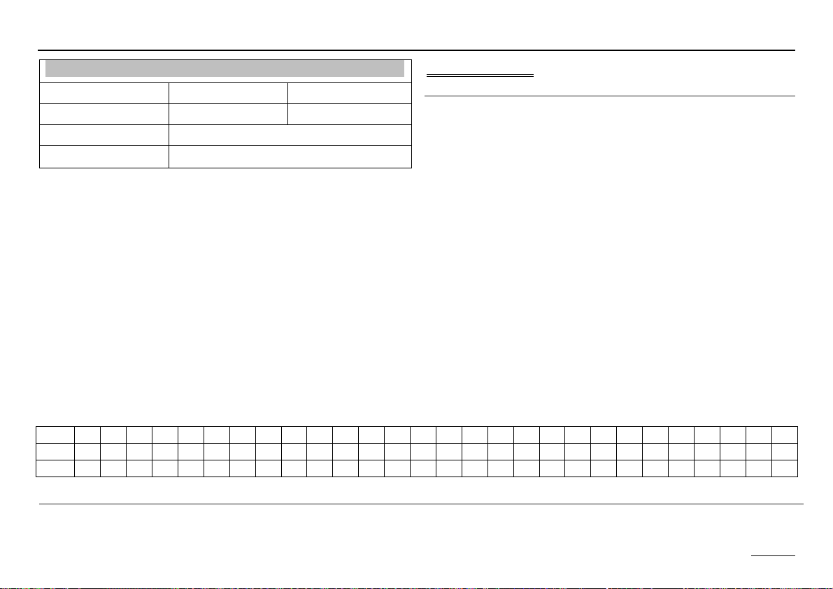
DAY 1 2 3 4 5 6 7 8 9 10 11 12 13 14 15 16 17 18 19 20 21 22 23 24 25 26 27 28
VT 25 25 25 55 55 55 55 25 40 55 55 55 55 55 55 55 55 55 55 40 25 --- --- --- --- --- --- --=>
SCREED PROGR (Program setting)
Ä => Screed program; Ç Select day; Ä => Activate adjustment date; Ç Set flow temperature;
Ä => Save setting; Ç Select next day or exit screed program using "RETURN" + Ä.
45
Page 46

Expert area Part 2: Overview of display values and settings
Hot water
Designation Value range Default IV
DHW RELIEF 00, 01
(OFF/ON)
PARALLEL DHW 00, 01, 02, 03 01
T-HS DHW 00K – 50K 20K
HYST DHW 5K – 30K 5 K
DHW FOLLOWUP 00 min – 30
min
THERM INPUT 00, 01
(OFF/ON)
WALL HUNG 00, 01
(OFF/ON)
LOAD THROUGH 00, 01
(OFF/ON)
RETURN
Exit level using Ä
DHW RELIEF (Charge pump blocking)
The charging pump is not switched until the boiler
temperature exceeds the storage tank temperature by 5K.
It is switched off when the boiler temperature drops below
the storage tank temperature. This prevents the storage
tank from being cooled by the boiler when hot water
preparation starts.
01 = ON
00 min
00 = OFF
00 = OFF
00 = OFF
PARALLEL DHW (Pump parallel running)
00 => Hot water priority operation: The heating circuits are
blocked during hot water preparation. The mixers close
and the heating circuit pumps switch off.
01 => HW partial priority
: The heating circuits are blocked
during hot water preparation. The mixers close and the
heating circuit pumps switch off. The mixer
circuits are
enabled again when the boiler has reached the
temperature of hot water temperature setting + boiler
superheating
[T-DHW + T-HS DHW]. If the boiler temperature drops
below the enable temperature by the switching hysteresis
[HYST DHW] again, the mixer circuits are blocked again.
02 => Pump parallel running
: Only the direct heating
circuits are blocked during hot water preparation. The
mixer circuits continue to be heated. The hot water
preparation is extended by this function.
03 => Pump parallel running also for the direct heating
circuit: During hot water preparation all heater circuits
continue to be heated. The hot water preparation is
extended by this function. When the boiler temperature
exceeds the maximum flow temperature of the direct
heating circuit by 8K, the heating circuit pump for this
circuit is switched off (overheating protection). The heating
circuit pump is switched on again when the boiler
temperature drops below the temperature [maximum flow
temperature + 5K].
46
Page 47

Part 2: Overview of display values and settings Expert area
T-HS DHW (increase during HW operation)
Boiler temperature setting with hot water preparation =
hot water temperature setting + T-HS DHW
! The boiler must be run at a higher temperature
during hot water preparation so that the hot water
temperature in the storage tank can be reached via
the heat exchanger.
HYST DHW (hot water hysteresis)
Hot water preparation is started when the temperature of
the hot water storage tank drops below the temperature
setting by the hysteresis [HYST DHW]. The hot water
preparation stops when the storage tank reaches the
temperature setting (the temperature setting is set to 65°C
during hot water short time heating operation).
DHW FOLLOWUP (pump run-down time)
00 min => Standard function: The charging pump
continues to run for 5 minutes after the burner has
switched off.
If heat is requested by a heating circuit the run-down is
cancelled.
The charge pump blocking kicks in and can also cause the
run-down function to be cancelled.
greater than 00 min
set time when storage tank charging is complete. The
after-run can only be cancelled by the activated charge
pump blocking.
=> The charge pump runs down by the
THERM INPUT (storage tank with thermostat)
00 => Hot water preparation via storage tank sensor
01
=> Hot water preparation via thermostat:
The hot water preparation is started by a short circuit at the
storage tank sensor connecting terminals. It stops when
the short circuit is removed.
WALL HUNG (for modulating HS)
Boiler temperature setting with hot water preparation =
hot water actual
With this function the exhaust gas losses occurring during
hot water preparation can be reduced with modulating heat
generator using the adapted boiler temperature setting.
LOAD THROUGH (only with F12 = T-DHW-LOWER)
The charge through function can be activated by
connecting a hot water storage tank, lower, sensor.
T-DHW = Temperature of hot water tank in removal area
(plug I, pin 6+7)
Storage tank charging:
ON: T-DHW < T-DHW DES - HYST DHW
OFF: T-DHW L > T-DHW DES
The charging process of the storage tank only terminates
when the lower storage tank set temperature has been
reached.
temperature + T-HS DHW
47
Page 48

Expert area Part 2: Overview of display values and settings
The parameters in this level change in accordance with the
heating circuit function that has been selected
[HC FUNCTION]
Heating circuit I / II
Designation Value range Default IV
HC FUNCTION 00 - 04 00
PUMP MODE 00 - 03 00
MIXER OPEN (not for
5-25 18
HW circuit)
MIXER CLOSE (not
5-25 12
for HW circuit)
See following pages for continuation
HC FUNCTION (heating circuit function selection)
If this parameter is modified the controller is restarted.
"RESET" briefly appears in the display.
02 => Swimming pool control (only for heating circuit II)
This function can be used to heat a swimming pool. The
mixer controls the flow temperature for the swimming pool
heat exchanger. The swimming pool water temperature
sensor is connected to the room sensor connection for the
heating circuit (see FBR).
[Plug III; 1+2]
The flow temperature control operates like normal room
control [ROOM INFL].
The set value for the water temperature can be entered in
the user area of the associated heating circuit level
[T-POOL 1/2/3]. The heating program operates. No
heating takes place during the reduction period (frost
protection only).
The water temperature and the current set value are
displayed in the display level [T-POOL/T-POOL DES].
03 => Hot water circuit
This function can be used to operate additional hot water
circuits. The heating circuit flow sensor is located in the hot
00 => Standard heating circuit
01 => Control to fixed flow temperatures
During the heating periods (see heating program ) the
heating circuit is operated with a fixed preset flow
temperature
[T-FLOW-DAY], and during reduced mode operation with a
fixed preset flow temperature [T-FLOW REDUC]
accordingly.
water storage tank.
The hot water temperature set value can be entered in the
user area of the associated heating circuit level [T-DHW
1/2/3]. The heating program for the heating circuit acts as
an enable program for the storage tank. The storage tank
set value is set to 10°C during the reduction period.
The boiler controller hot water priority function can be used
(partial priority acts like priority).
48
Page 49

Part 2: Overview of display values and settings Expert area
04 => Return flow temperature increase via mixer motor
The heating circuit flow sensor is used as a boiler return
flow sensor. The mixer motor controls to the heating circuit
set value for 24 hours [MIN T-FLOW].
Installation tip: Mixer motor OPEN => boiler flow is fed
into the return (=> return flow temperature increase)
Mixer motor CLOSED => heating circuit return is passed
through. When the mixer motor is open it must be ensured
that there is circulation through the boiler (boiler pump).
PUMP MODE (pump operating mode)
The circulation pumps are switched off if heating is not
required. The mixer motors are closed at the same time =>
"The heating circuit is switched off".
(Switch on with 1K hysteresis)
This adjustment concerns the weather dependent shut-
down. If room temperature regulation is enabled (ROOM
INFL > 0) the "thermostat function" takes effect in addition.
• Room temperature > room set value + 1K
00 => Standard circulation pump control
Heating time:
• Outside temperature > room set value + 1K
Reduction period:
ROOM INFL = 0
• The switch-off occurs during the transition to reduction
operation.
• Switch on with: Room temperature < room set value
The pump runs continuously after switching on.
ROOM INFL ="--":
• Flow temperature setting < 20°C.
01 => Pump switching in accordance with heating limits
Heating time:
• Outside temperature < daytime heating limit setting +
1K
Reduction period:
• Outside temperature < night-time heating limit setting +
1K
02 => Pump switching in accordance with heating program
Heating time:
• Pump is ON; Heat circuit is enabled
Reduction period:
• Pump is OFF; Heat circuit is blocked
03 => Continuous operation
The runs continuously for 24 hrs.! The heating circuit is
permanently enabled.
MIXER OPEN (open mixer dynamic)
Speed setting at which the mixer motor opens when a
control difference occurs. The control difference at which
the mixer motor opens without interruption is entered in
Kelvin.
! Small values cause the mixer motor to adjust quickly
and can lead to oscillation.
49
Page 50

Expert area Part 2: Overview of display values and settings
MIXER CLOSE (close mixer dynamic)
Speed setting at which the mixer motor closes when a
control difference occurs. The control difference at which
the mixer motor closes without interruption is entered in
Kelvin.
! Small values cause the mixer motor to adjust quickly
and can lead to oscillation.
Heat circuit I/II
Designation Value range Default IV
MAX T-FLOW 20°C - 110°C 80°C
MIN T-FLOW 10°C - 110°C 10°C
T-FROST PROT ----;
(-15)°C – (5)°C
T-OUT DELAY 0:00 – 24:00 0:00
SLOPE OFFSET 0K – 50K 5 K
B-HEAT SINK 00, 01
(OFF/ON)
RETURN
MAX T-FLOW (max. flow temperature)
The measured temperature setting for the heating circuit
flow is limited to the maximum flow temperature setting
(overheating protection).
Exit level using Ä
0°C
01 = ON
E The pump of the direct
off until the boiler temperature exceeds the set
maximum flow temperature by 8K. The heating circuit
pump has already been switched on again when the
boiler temperature drops below the temperature
[maximum flow temperature + 5K].
MIN T-FLOW (min. flow temperature)
The measured temperature setting of the heating circuit
flow is increased to the minimum flow temperature setting
(e.g. with air heating).
T-FROST PROT (frost protection temperature)
If the outside temperature drops below the programmed
value, the system switches to frost protection mode
(pumps are switched on).
"----" Frost protection mode is deactivated!
T-OUT DELAY (outside temperature delay)
The selected outside temperature delay must be matched
to the type of construction of the building. In the case of
heavy structures (thick walls), a long delay must be
selected since a change in outside temperature affects the
room temperature later accordingly. With light structures
(walls have no storage effect) the delay should be set
(0 hrs.).
heating circuit is not switched
50
Page 51

Part 2: Overview of display values and settings Expert area
SLOPE OFFSET (heating slope distance)
The boiler temperature that is required for a mixer circuit is
calculated by adding the calculated temperature setting for
the heating circuit flow to the heating curve distance. The
heating curve distance compensates for sensor tolerances
and heat loss up to the mixer.
B-HEAT SINK (circuit enable)
00 => OFF
01 => The heating circuit can be used by higher-order
functions (e.g. cooling function of a heat generator to
protect from overheating; heat removal during service
mode) as a heat sink/consumer. The heating circuit is
heated at the maximum flow temperature setting for the
duration of the function.
51
Page 52

Expert area Part 2: Overview of display values and settings
Solar/MF
FUNC RELAY 1 (function selection relay MF1)
Designation Value range Default IV
FUNC RELAY (1-4) 00 - 26 00,00,01,02
T-MF(1-4) SETP 30°C - 90°C 30°C
MF(1-4) HYST 2K – 10K 5 K
F15 FUNCTION 00 - 03 00
RETURN
Auxiliary relay functions
Exit level using Ä
The multifunction relays = MF relay is assigned one basic
function respectively
MF-1: Mixer HC1 OPEN (FUNC RELAY 1 = 00)
MF-2: Mixer HC1 CLOSED (FUNC RELAY 2= 00)
MF-3: Header pump (FUNC RELAY 3 = 01)
MF-4: Circulation (time) (FUNC RELAY 4 = 02)
If this basic function of a MF relay is not required
(configuration of the installation in Installation level), any
one of the functions described below may be selected for
any unused relay.
The MF-relay
sensor
1-4 (A8-A11) is always assigned with a
1-4 (F11-F14) (applies for functions starting from
„20“ only).
If a further sensor is required for a function, this sensor
must be connected as F17 (connector III, Pin 2+3).
The functions that may be selected for the MF relays
1-4
are described using MF relay 1 as an example.
T-MF1 SETP (switching temperature relay MF1)
MF 1 HYST (hysteresis relay MF1)
00 = No MF function
01 = Header pump
ON: When heat is requested by a consumer
OFF: Without consumer heat request
If at least one consumer in the system requests heat the
pump is switched on. The after-run function runs after the
burner has been switched on.
02 = Circulation (time)
Switching the relay according to the time program for the
circulation pump
03 = Booster pump
ON: When heat is requested by an internal consumer
OFF: When no heat is requested by an internal consumer.
Follow-up pump action occurs.
05 = Pump HS1
The relay may be used to control boiler pump for heat
generator 1.
(Relay switches with burner relay 1; run-down =5 min)
52
Page 53

Part 2: Overview of display values and settings Expert area
06 = Pump HS2
When using the controller to control two heat generators
the relay may be used to control the pump for HS 2.
(Relay switches with burner relay 2; run-down =5 min)
20 = Temperature-controlled circulation pump
T-CIRCL = Return flow temperature of circulation line
ON: T-CIRCL < T-MF1 SETP
OFF: T-CIRCL > [T-MF1 SETP + MF 1 HYST]
The circulation pump is switched on when the return flow
temperature drops below the temperature setting limit
(T-MF1 SETP). The pump is switched off again when the
return flow temperature exceeds the set limit temperature
by the Hysteresis (MF 1 HYST).
The set circulation program and the "Circulation with hot
water" setting have an overriding function
=> Switching on only takes place during enable periods.
21 = Pulsed circulation pump
ON: With short circuit at assigned sensor input
OFF: After 5 minutes
If a short-cut occurs at the multifunction sensor input the
circulation pump is switched on for 5 minutes. Switching on
takes place on the edge (once only).
The set circulation program and the "Circulation with hot
water" setting have an overriding function
=> Switching on only takes place during enable periods.
22 = Solid fuel boiler integration
(e.g. in connection with 2-stage HS)
T-MF1 or 1-4 = Temperature of the solid fuel boiler
T-BUFFER B = Temperature of buffer storage in the infeed
area [F1]
ON: T-MF1 > [T-BUFFER B (F1) +MF 1 HYST + 5K]
OFF: T-MF1 < [T-BUFFER B (F1) + MF 1 HYST]
Start-up relief:
ON: T-MF1 > T-MF1 SETP
OFF: T-MF1 < [T-MF1 SETP – 5K]
The pump is switched on when the temperature of the
solid fuel boiler exceeds the temperature of the buffer
storage in the infeed area [T-BUFFER B (F1)] by the
hysteresis [MF 1 HYST+ 5K]. Switching off occurs when
the temperature drops 5K below the switch-on
temperature.
Switching off also occurs when the temperature of the solid
fuel boiler drops below the set limit temperature [T-MF1
SETP] by 5K. The pump is enabled again when the
temperature of the solid fuel boiler exceeds the set limit
temperature [T-MF1 SETP].
Blocking HS1:
ON: T-MF1 > HS set temperature + 5K and solid-fuel
boiler pump = ON
OFF: T-MF1 <= HS set temperature or solid-fuel boiler
pump = OFF
53
Page 54

Expert area Part 2: Overview of display values and settings
23 = Solar integration (to MF4 because of PT1000
sensor)
T-SOL PANEL [T-MF4] = Temperature of the solar
collector
T-DHW L [F12]= Temperature of hot water storage tank in
infeed area
ON: T-SOL PANEL >
[T-DHW L + MF4 HYST + 5K]
OFF: T-SOL PANEL <
[T-DHW L + MF4 HYST]
The pump is switched on when the temperature of the
solar collector exceeds the temperature of the storage tank
in the infeed area (T-DHW L) by the Hysteresis (MF4
HYST + 5K). Switching off occurs when the temperature
drops 5K below the switch-on temperature.
Safety / system protection:
OFF: T-DHW B > T-MF4 SETP
ON: T-DHW B < [T-MF4 SETP – 5K]
Switching off occurs when storage tank temperature
exceeds the set limit temperature (T-MF4 SETP). The
pump is enabled again when the storage tank temperature
drops below the limit temperature by 5K.
24 = Return flow temperature increase HS1
T-RETURN 1 = Return flow temperature from the
installation [= T-MF1 or 1-4].
ON: T-RETURN 1 < T-MF1 SETP
OFF: T-RETURN 1 > [T-MF1 SETP +MF 1 HYST]
The return flow temperature increase pump is switched on
if the return flow temperature drops below the temperature
setting limit (T-MF1 SETP). It is switched off again when
the return flow temperature exceeds the temperature
setting limit by the Hysteresis (MF 1 HYST).
25 = Return flow temperature increase HS2
T-RETURN 2 = Return temperature of system
ON: T-RETURN 2 < T-MF1 SETP
OFF: T-RETURN 2 > [T-MF1 SETP +MF 1 HYST]
The return flow temperature increase pump is switched on
if the return flow temperature drops below the temperature
setting limit (T-MF1 SETP). It is switched off again when
the return flow temperature exceeds the temperature
setting limit by the Hysteresis (MF 1 HYST).
26 = Return flow temperature increase HS via buffer
storage
ON: T-BUFFER B [F1] > T-MF1 +MF 1 HYST + 5K
OFF: T-BUFFER B < T-MF1+MF 1 HYST
The valve to the return flow temperature increase via the
buffer storage is opened if the temperature buffer storage
low [T-BUFFER B] exceeds the return flow temperature of
the installation [sensor
1 or 1-4] by the Hysteresis (MF 1
HYST + 5K). It is switched off again when the temperature
buffer storage low drops below the return flow
temperature.
54
Page 55

Part 2: Overview of display values and settings Expert area
F15 FUNCTION (sensor function F15)
00 = Room sensor for heating circuit 2. If a further sensor
at the pulse input [IMP] is detected at this position an FBR
is evaluated.
01 = 0-10V input => For Preset Collector set temperature.
On evaluation see parameter V-CURVE in the
expert/installation level.
02 = light sensor (for plausibility testing with solar – no
function in version V1).
03 = 0-10V input preset for modulation. On evaluation see
parameter V-CURVE in the expert/installation level.
55
Page 56

Expert area Part 3: General function description
Part 3: General function description
Part 3: General function description
Heat circuit control
Weather-dependent control
The boiler or flow temperature is determined via the set
heat slope to suit the measured outside temperature in
such a way that the set value for the room is approximately
set if the heating system is configured correctly.
=> Exact setting of the heat slope is extremely important
for weather-dependent control.
The circulation pump is controlled weather-dependently.
The circulation pump is switched on if there is a heating
demand and in Frost-protection mode.
Room sensor influence
The current room temperature can be included in
computation of the required flow temperature via a present
room temperature sensor.
The influence factor (parameter list) can be set between 0
(fully weather-dependent regulation) and 20 (room
temperature regulation with minimal outdoor temperature
influence). Position "----" deactivates room temperature
control. Positions "----" and "0" indicate differences for
demand-dependent circulation pump control.
Hot water generation
The programmed hot water temperature is stabilised by
switching the hot-water cylinder charging pump and the
burner. Storage tank charging starts when the storage tank
temperature drops below the temperature setting by 5K.
Storage tank charging stops when the temperature setting
is reached.
OwB => operation without burner
For operation with solar energy for instance. In this
operating mode the burner is only enabled when values
drop below the set tolerance limit.
Frost protection function
The frost protection circuit prevents the heating system
from freezing by automatically switching heating operation
on.
Outdoor sensor frost protection
If the measured outside temperature drops below the set
frost protection temperature the room temperature setting
is set to 5°C for the relevant heating circuit. The heating
circuit is enabled:
• the pumps are switched on
• the heat request is sent to the boiler
"----" => outdoor sensor frost protection deactivated
56
Page 57

Part 3: General function description Expert area
The function stops when the outside temperature
increases to 1K above the frost protection temperature
setting.
Boiler frost protection
eBUS burner controls
The controller supports the operation of burner controls via
the implemented eBUS. The unit is connected by means of
the connector VII (FA eBUS).
Boiler frost protection is activated when the boiler
temperature drops below 5°C. The boiler is switched on
until the boiler temperature exceeds the "MINIMUM
BOILER TEMPERATURE".
Flow or storage tank sensor frost protection
The sensor frost protection is activated when the flow or
storage tank temperature drops below 7°C. Only the
relevant pump is switched on.
The sensor frost protection is deactivated when the flow or
storage tank temperature increases to above 9°C.
Frost protection via room sensor
If the room temperature drops below 5°C the frost
protection function is activated.
The room temperature setting for the relevant heating
circuit is set to 5°C. The heating circuit is enabled:
• the pumps are switched on
• the heat request is sent to the boiler
Heat request: Controller => Burner / FA
05h07h [in data byte 7 = Process water desired value the
burner must not interpret bit 7] additionally
Data/Status: Burner/FA => Controller
05h03h
Requirements for operation:
The burner control unit (FA) must transmit a valid eBUS
message.
The eBUS supply must be activated if the burner does not
also supply the BUS => Expert/System (tap without
information => Test function with and without eBUS
supply)
EEPROM check
Every 10 minutes, a check is conducted automatically in
order to establish whether the settings of the controller lie
within the specified limits. If a value is found to be out-ofrange, it is substituted by the related default value. The
range transgression is indicated by the blinking E and the
error number 81.
57
Page 58

Expert area Part 3: General function description
In this case, the user should check the important settings
of the controller. The warning symbol is cleared after the
unit is restarted (RESET).
Circulation pump control
Switched according to heating requirement
Demand-dependent circulation pump control (automatic
summertime switchover) switches the circulation pumps off
if there is no heating demand. The mixers are closed at the
same time.
Conditions for switch-off:
Room temperature-dependent control
The room temperature exceeds the set desired
temperature.
Weather-dependent control
Outside temperature exceeds room temperature set value
or flow temperature set value drops below 20°C.
! If the room temperature factor is "0", the pump
continues to run during the reduced operation period
after a one-off heating demand.
Switched according to heating limits
If the outside temperature that is measured and calculated
by the controller exceeds the heating limit specified here,
heating is disabled, the pumps switch off and the mixers
are closed. The heating is enabled again when the outside
temperature drops below the set heating limit by 1K
(= 1°C).
T-LIMIT DAY => applies during heating times
T-LIMIT N => applies during reduction times
Delayed pump switch-off
In the case of switch-off of the circulation pumps, the
circulation pumps are not switched off until 5 minutes later
if one of the burners was on during the last 5 minutes
before the switch-off instant.
Pump blocking protection
The controller effectively prevents blocking of the pumps if
they are not switched on for long periods. The integrated
protection function switches on all pumps which have not
been in operation during the past 24 hours for 5 seconds
at 12.00 h ours every day.
Mixer motor blocking protection
If the mixer motor has not moved for 24 hours it is fully
opened at approximately 03:00 hrs. (once only). The
heating circuit pump is switched off during this time. The
maximum flow temperature is monitored. Cancelled at
maximum flow temperature – 5K.
58
Page 59

Part 4:Appendix Remote controls
Part 4:Appendix
Remote controls
Operation-control module Merlin BM, BM 8, Lago FB
(Only for controller models with CAN-Bus connection)
Remote control FBR2
Connection for HC1: Connector I; (2+collective ground+3)
Connection for HC2: Connector III; (1-3)
Electrical connection: Connector IX; 1-4
The controller permits connection of an operation-control
module BM for each heating circuit via a bus line. The
operation-control module allows various operation-control
functions and monitoring functions for the system values to
be relocated to the main controlled zone – i.e. the living
room. This achieves maximum comfort and convenience.
Please refer to the technical description of the BM for a
precise description of the overall scope of functions.
• Display of the system parameters
• Entry of the heating circuit parameters
• Room temperature control
• Automatic adaptation of the heat slope (not Lago FB)
• Rotating switch for modifying room temperature setting
Adjusting range: (±5 K)
• Room control via the integrated room sensor
• Rotating switch for selecting operating mode
i Standby/OFF (frost protection only)
q
Automatic mode (according to timer program 1 in
1
1
2
controller)
q
Automatic mode (according to timer program 2 in
2
controller)
e
t
e
s
R
C 24-hour night operation (reduction temperature)
B 24-hour daytime operation (comfort temperature)
F Summer mode (heating OFF, hot water only)
! The operating mode at the controller must be set
to
q.
The controller can also be operated with an FBR1.
59
Page 60

Remote controls Part 4:Appendix
DCF receiver
Electrical connection: Connector VII; Terminal 1,2
The controller can evaluate a eBUS DCF receiver on the
eBUS FA-Terminals.
If the DCF receiver is connected, the controller time is
updated as soon as the DCF transmits a valid time on the
BUS.
If the time has not been corrected after max. 10 min, select
a different place of installation for the DCF (e.g. another
wall - not in proximity to TV devices, monitors or dimmers).
PC
All system-specific parameters can be set and interrogated
using the
ComfortSoft parameterisation software. The
parameters can be saved, displayed graphically and
evaluated on the PC at predefined intervals. T connect to a
PC you need the optical adapter or CoCo PC active, which
also supports the sending of error messages by SMS and
the remote interrogation of controller data.
Telephone switch
1
1
12
FBR
3
32
1
1
FBR
3
32
The heating system can be switched to Heating mode h
with a telephone switch. The connection terminals of the
controller for the remote control FBR (see connection
diagram) are used for installation. As soon as a short
circuit between terminal 3 of the FBR and ground (FBR
terminal 2) is detected, the assigned heating circuit is
switched to heating mode. Additionally the hot water
preparation is activated (only for controllers with hot water
preparation). When the short-circuit is eliminated, the
controller once again heats on the basis of the set heating
program.
E If the heating circuit is controlled remotely by an
operating module, the telephone switch must be
connected at the operating module.
60
Page 61

Part 4:Appendix System bus
System bus
The heating system
This controller can be expanded in a modular fashion
using additional modules that are connected via the
integrated bus. In its maximum configuration, the system
can be used to control the following heating system
components
1-8 Boiler (modulating or switching)
1-15 Mixed weather-dependent heating circuits
0-15 Room controller (digital or analogue)
1 Solar system (2 collectors, 2 storage tanks)
1 Solid fuel boiler
The various components are simply coupled to the system
bus. The modules log on to the system automatically and
search for their communication partners via the defined
bus IDs (heating circuit number or boiler number).
61
Page 62

System bus Part 4:Appendix
Error messages
Error Error description
Communication error
E 90 Adr. 0 and 1 on bus. Bus IDs 0 and 1 may not be
used simultaneously.
E 91 Bus ID used. The set bus ID is already in use by
another device.
E 200 Communication error HS1
E 201 Communication error HS2
E 202 Communication error HS3
E 203 Communication error HS4
E 204 Communication error HS5
E 205 Communication error HS6
E 206 Communication error HS7
E 207 Communication error HS8
Internal error
E 81 EEPROM error. The invalid value has been
replaced with the default value
E Check parameter values!
Sensor defective (break/short circuit)
E 69 F5: Flow sensor HC2
E 70 F11: Flow sensor HC1, sensor Multifunction1
E 71 F1: Buffer storage tank low sensor
E 72 F3: Buffer storage tank top sensor
E 75 F9: Outdoor sensor
E 76 F6: Storage tank sensor
E 78 F8: Boiler sensor / Collector sensor (cascade)
E 80 Room sensor HC1, F2: F2 Buffer storage tank low
sensor
E 83 Room sensor HC2,
F15: Pool sensor (T-Storage 3)
E 135 F12: HW Storage tank low sensor, Multifunction 2
E 136 F13 (PT1000): HS2, Collector2, Multifunction 3
E 137 F14 (PT1000): Collector 1, Multifunction 4
If a fault or error occurs in the heating system, you will see
a blinking warning triangle (E) and the related error
number on the controller display. Please refer to the table
below for the significance of the displayed error code.
The system must be restarted after a fault has been
remedied => RESET.
RESET : Brief device shut-off (mains switch). Controller
restarts, reconfigures itself and continues to operate with
the values that have already been set.
RESET+ Ä : Overwrite all settings with default
values (except time).
The additional button (Ä) must be pressed when the
controller is switched on (mains on) until "EEPROM"
appears in the display.
62
Page 63

Part 4:Appendix Troubleshooting
Troubleshooting
General
If your system malfunctions you should first check that the
controller and the control components are correctly wired.
Sensors:
All sensors can be checked in the "General/Service/Sensor
test" level. All the sensors that are connected must appear
in this level with plausible measurements.
Actuators (Mixer motor, pumps=>only with code no.):
All actuators can be checked in the "General/Service/Relay
test" level. All relays can be individually switched using this
level. This makes it easy to check whether these
components have been correctly connected (e.g. mixer
motor direction of rotation).
BUS connection:
In control devices with connection to
Mixer motor => Communication symbol appears in
standard display ("
" or "v" depending on version)
Boiler controller => Outside temperature and boiler
temperature display (see "Display/Installation")
In boiler controller with connection to
Control unit => Room temperature displayed and current
room temperature setting blanked out "----" (see
"Display/Heating circuit")
In mixer motor expansion controllers with connection to
Boiler controller => Outside temperature and boiler
temperature display (see "Display/Installation")
Control unit => Room temperature displayed and current
room temperature setting blanked out "----" (see
"Display/Heating circuit")
In case of communication problems
Check connecting cables: Bus lines and sensor lines must
be laid separately, away from mains cables! Poles
switches?
Check bus feed: There must be at least 8V DC between
the "+" and "-" terminals of the BUS connector (connector
IX, terminals 3+4). If you measure a lower voltage, an
external power supply must be installed.
Pumps do not switch off
Check manual / automatic switch => Check automatic
pump switching
=> pump switching mode
Pumps do not switch on
Check operating mode => Standard
F (test B)
Check time and heating program => Heating time
Check pump switching mode:
Default => Outside temperature > Room set temperature?
Heating limits => Outside temperature > Valid heating limit?
Room control => Room temperature > Temperature setting + 1K
63
Page 64

Technical data
Burner does not switch of
at correct time
Check minimum boiler
temperature and type of
minimum delimiter => Protect
from corrosion
Burner will not switch on
Check boiler temperature
setting => The temperature
setting must be greater than
the boiler temperature.
Check operating mode =>
Standard
F (test B)
With solar: Check burner
blocking (BOB)
Supply voltage to IEC 38 230 V AC ± 10%
Power consumption Max. 8 VA
Switching capacity of the relays 250 V 2(2) A
Maximum current on terminal L1' 10 A
Enclosure to EN 60529 IP 40
Safety class II to EN 60730 Totally insulated
Switch panel installation in acc. with
DIN IEC 61554
Power reserve of the timer > 10 hours
Permitted room temperature
during operation
Permitted room temperature
during storage
Sensor resistances
Tolerance in ohms
Temperature tolerance
Tolerance in ohms
Temperature tolerance
Tolerance in ohms
Technical data
Recess 138x92
0 to 50°C
- 20 to 60 °C
NTC 5 kΩ (AF,KF,SPF,VF)
± -1% at 25°C
+/- 0.2K at 25°C
PTC 1010Ω (AFS,KFS,SPFS,VFAS)
± -1% at 25°C
+/- 1.3K at 25°C
PT1000 sensor with 1 kΩ +/- 0,2%
at 0 °C
64
Malfunctions due to improper operation or settings are not
covered by the warranty.
EN 0608 6.6701.902-09 Printed in Germany, Subject to modification
 Loading...