

Page 1
F
NL
I
E
057 · Edition 08.
D GB F NL I E
TR CZ PL RUS H
DK S N P GR
➔ www.docuthek.com
Operating instructions
Pressure switches for gas DG..H, DG..N Pressure switch for gas DG..I
Translation from the German
© 2012 Elster GmbH
Contents
Contents
Pressure switches for gas DG..H, DG..N
Pressure switch for gas DG..I .............
Contents ..............................
Safety.................................
Checking the usage .....................
Type code .............................2
Part designations ........................2
Type label.............................. 2
Installation ............................
Connection facilities ......................3
Installing DG..H, DG..N ...................3
Installing DG..I ..........................4
Wiring ................................4
Adjustment ............................5
Tightness test ..........................5
Maintenance ...........................5
Accessories ...........................5
Technical data .........................7
Designed lifetime ........................8
Declaration of conformity ................8
Contact ...............................8
Safety
Safety
Please read and keep in a safe place
Please read through these instructions
carefully before installing or operating. Following the
installation, pass the instructions on to the operator. This unit must be installed and commissioned
in accordance with the regulations and standards
in force. These instructions can also be found at
www.docuthek.com.
Explanation of symbols
• , , , ... = Action
▷ = Instruction
Liability
We will not be held liable for damages resulting
from non-observance of the instructions and noncompliant use.
Safety instructions
Information that is relevant for safety is indicated in
the instructions as follows:
DANGER
Indicates potentially fatal situations.
WARNING
Indicates possible danger to life and limb.
CAUTION
Indicates possible material damage.
All interventions may only be carried out by qualified
gas technicians. Electrical interventions may only be
carried out by qualified electricians.
Conversion, spare parts
All technical changes are prohibited. Only use OEM
spare parts.
Transport
On receipt of the product, check that the delivery is
complete (see Part designations). Report any transport damage immediately.
Storage
Store the product in a dry place. Ambient temperature: see Technical data.
GB
GB-1
Page 2

F
NL
I
E
Checking the usage
-6 -5 -4 -3 -2 -1 0 1 2 3 4 5 6
Increasing
DG..H, DG..N, DG..I
For monitoring increasing and decreasing gas or
air pressure.
negative pressure
Decreasing
negative pressure
Increasing pressure
Decreasing pressure
Type label
D-49018 Osnabrück, Germany
DG
CE – 0085AP0467
2
1
3
Positive
pressure
DG..H,
DG..N
GB
DG..I Air, flue gas
Gas, air, flue
gas
Negative
pressure
Differential
pressure
Air, flue gas Air, flue gas
Gas, air, flue
gas
Air, flue gas
DG..H switches and locks off with rising pressure,
DG..N switches and locks off with falling pressure.
They can be unlocked using the manual reset.
This function is only guaranteed when used within
the specified limits– see page 7 (Technical data).
Any other use is considered as non-compliant.
Type code
Code Description
DG Pressure switch for gas
,5 – 500 Max. setting in mbar
H
N
I
Locks off with rising pressure
Locks off with falling pressure
Negative pressure for gas
G With gold-plated contacts
-
-4
-5
-6
-9
K
T
T
N
4-pin plug, with socket, IP 65
Red/green pilot LED for 24 V DC/AC
Red/green pilot LED for 230 V AC
Electrical connection
via screw terminals
via screw terminals, IP 65
4-pin plug, without socket
4-pin plug, with socket
Blue pilot lamp for 230 V AC
Blue pilot lamp for 120 V AC
A External adjustment
Part designations
2
1
5
3
4
Upper housing section with cover
Lower housing section
Hand wheel
4 M16 cable gland
5 DG..H, DG..N with manual reset
Max. inlet pressure, mains voltage, ambient tem-
perature, enclosure: see type label.
Installation
CAUTION
Please observe the following to ensure that the DG
is not damaged during installation and operation:
– Continuous operation at high temperatures accel-
erates the ageing of elastomer materials. In places
where a high thermal capacity is required, thermal
equipment trips must be installed upstream of
theDG.
– Use approved sealing material only.
– Check max. ambient temperature – see
page7 (Technical data).
– When using silicone tubes, only use silicone tubes
which have been sufficiently cured.
– Vapours containing silicone must not be allowed
to get into the housing.
– Condensation must not be allowed to get into the
housing. At subzero temperatures malfunctions/
failures due to icing can occur.
– The service life will be shorter if subject to ozone
concentrations exceeding 200μg/m3. When in-
stalling outdoors, place the DG in a roofed area
and protect from direct sunlight (even IP65 ver-
sion). To avoid condensation, a cover with pres-
sure equalization element (see page6 (Pres-
sure equalization element)) can be used.
– Avoid subjecting the DG to strong or violent vibra-
tions.
– In case of highly fluctuating pressures, install a
restrictor orifice (see page6 (Restrictor orifice)).
▷
The DG must not be in contact with masonry.
Minimum clearance 20mm.
▷ Ensure that there is sufficient installation space.
▷ Ensure unobstructed view of the hand wheel.
▷ Installation position as required, preferably with
vertical diaphragm. Then the switching pointpS
corresponds to the scale valueSK set on the
hand wheel. In other installation positions, the
switching pointpS will change and no longer
correspond to the scale valueSK set on the
hand wheel. Check the switching point.
GB-2
Page 3
F
NL
I
E
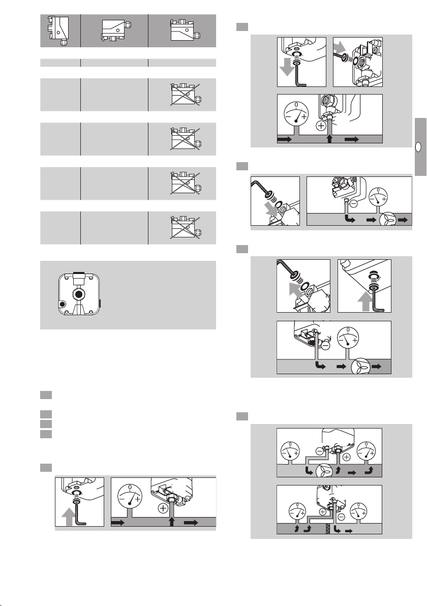
Positive pressure measurement at port
2
p
max
=
600 mbar
Rp 1/4
1
3
Rp 1/8
4
p
max
=
-600 mbar
5 Seal port.
p
= SK pS = SK + 0.18 mbar pS = SK - 0.18 mbar
S
= SK pS = SK - 0.5 mbar
p
S
= SK pS = SK - 0.2 mbar
p
S
= SK
p
S
= SK
p
S
DG..H, DG..N
DG 18I
DG 120I, DG 450I
DG 1,5I
Negative pressure:
p
= SK - 0.4 mbar
S
Positive pressure:
p
= SK + 0.4 mbar
S
DG 12I
Negative pressure:
p
= SK - 0.5 mbar
S
Positive pressure:
p
= SK + 0.5 mbar
S
Connection facilities
2
1
3
▷
Ports and 4 are suitable for air and flue gas only.
▷
If the electrical contacts in the DG could be soiled
1 and 2
Gas, air, flue gas
3 and 4
4
Air, flue gas
by dirt particles in the surrounding air or in the
medium, use a filter pad (see page5 (Filter
pad set)) at port/4. On IP65 units, the filter pad
is fitted as standard, see type label.
Disconnect the system from the electrical power
supply.
Shut off the gas supply.
Ensure that the pipeline is clean.
4 Purge the pipe.
Installing DG..H, DG..N
Positive pressure measurement at port
5 Seal port.
2
1
Rp 1/4
p
=
max
600 mbar
0
2
1
Rp 1/4
2
p
=
max
600 mbar
Rp 1/4
p
=
max
Negative pressure measurement at port4
5 Seal port.
Rp 1/8
p
=
max
4
-600 mbar
3
Negative pressure measurement at port
5 Seal port4.
0
4
3
3
p
=
max
-600 mbar
Differential pressure measurement
▷ Use port or for the higher absolute pressure
and port or 4 for the lower absolute pressure.
5 Seal the remaining ports.
600 mbar
∆p
max
600 mbar
∆p
=
max
=
Rp 1/8
3
1
1
3
GB
GB-3
Page 4

F
NL
I
E
Installing DG..I
2
p
max
=
-600 mbar
Rp 1/4
1
–
3 42
COM
3
▷
It is recommended that the port which is best
protected from dirt and water be left open.
Negative pressure measurement at port
5 Seal port.
Disconnect the system from the electrical power
supply.
3 42
2
1
Rp 1/4
p
max
–
-600 mbar
Negative pressure measurement at port
5 Seal port.
GB
0
2
1
Rp 1/4
2
p
=
–
Wiring
▷ If the DG..G has switched a voltage >24V and
a current >0.1A once, the gold plating on the
contacts will have been burnt through. It can
then only be operated at this power rating or
higher power rating.
▷
Pressure switch DG can be used in Zone1 and2
hazardous areas if an isolating amplifier is installed
upstream in the safe area as “Ex-i” equipment
pursuant to EN60079-11 (VDE0170-7):2007.
▷
DG as “simple electrical equipment” pursuant to
EN60079-11:2007 corresponds to the Temperature classT6, GroupII. The internal inductance/
capacitance is Lo= 0.2μH/Co= 8pF.
CAUTION
To ensure that the DG is not damaged during opera-
tion, note the switching capacity, see page7
(Technical data).
▷ In the case of low switching capacities, such as
24V, 8mA, for example, we recommend using
an RCmodule (22 Ω, 1μF) in air containing
silicone or oil.
C = 1 µF R = 22 Ω
NO
2
NC
1
max
-600 mbar
Rp 1/4
p
max
COM
3
=
=
5 6 7
M16 x 1,5:
ø 4,5–10 mm
▷
Contacts and close when subject to increasing pressure. Contacts and close when subject to falling pressure.
NO
L1
3
COM
2
NC
1
NO
1
2
NC
3
COM
DG ,5I and DG I
▷ The connection of DG 1,5l and DG 12l depends
on the positive or negative adjusting range.
7
-
6
1
2
-
1
1
-
1
r
0
a
b
m
-
9
7
–
1
-
;
8
1
-
-
7
-
6
5
1
0
0
P
4
a
=
1
3
m
b
a
2
r
1
1
–
2
1
-
-
5
-
s
p
=
2
-
3
-
-
4
1
,
5
.
.
.
.
;
-
5
1
,
0
.
-
–
.
5
.
,
1
.
-
-
0
=
,
s
5
.
p
.
.
.
.
.
.
-
,
0
.
.
.
3
.
.
m
b
a
3
–
5
0
,
.
.
.
r
5
,
.
2
.
.
.
1
0
2
.
0
P
.
a
.
=
.
1
5
m
,
b
a
1
r
.
.
.
.
1
5
.
.
.
.
DG 12I DG 1,5I
▷
In the negative adjusting range, the template
which can be found in the unit displays the connection diagram.
1
2
NC
NO
NC
NO
1
3
2
N
COM
µ
▷ In the positive adjusting range, remove the tem-
plate and wire the unit as shown in the engraved
connection diagram.
NO
NC
2
1
COM
3
GB-4
Page 5

F
NL
I
E
Adjustment
NO
2
NC
1
COM
3
COM
3
NC
1
NO
2
▷
The switching point is adjustable via hand wheel.
Disconnect the system from the electrical power
supply.
Detach the housing cover, see page7 (Tech-
nical data).
Connect an ohmmeter.
NO
1
2
NC
3
COM
NO
NC
COM
2
3
1
Tightness test
Shut off the downstream gas pipeline close to
the valve.
Open the valve and the gas supply.
▷ Check all used ports for tightness.
3 4
N2
900 mbar
max. 2 bar
< 15 min
4 Set the switching point using the hand wheel.
5 Connect a pressure gauge.
Maintenance
In order to ensure smooth operation: check the tight-
GB
ness and function of the DG every year, or every
0
six months if operated with biologically produced
methane.
1 cm = 1 mbar
6 Apply pressure. In doing so, monitor the switch-
ing point on the ohmmeter and the pressure
▷ A function check can be carried out in case of
decreasing pressure control e.g. with the PIA.
▷ After carrying out the maintenance work, check
for tightness, see page5 (Tightness test).
gauge.
Accessories
Connecting set
For monitoring a minimum and maximum inlet pressure pu with two pressure switches attached to one
another.
Type
Adjusting
range*
[mbar]
Reset pressure**
[mbar]
DG 10H, ..N 1 – 10 0.4 – 1
DG 50H, ..N 2.5 – 50 1 – 2
DG 150H, ..N 30 – 150 2 – 5
DG 500H, ..N 100 – 500 4 – 17
Type
DG 1,5I
DG 12I
Adjusting range*
[mbar]
-1.5 to -0.5 and
+0.5 to +3
-12 to -1 and
+1 to +7
DG 18I -2 to -18 0.5 – 1.5
DG 120I -10 to -120 4 – 11
Switching
differential***
[mbar]
0.2 – 0.5
0.5 – 1
Order No.: 74912250
1
2
2
1
Remove from
2
both pressure
switches.
DG 450I -80 to -450 10 – 30
* Adjusting tolerance = ± 15% of the scale value.
** Difference between switching pressure and pos-
sible reset.
*** Mean switching differential at min. and max. setting.
▷
Deviation from the switching point during testing
3
1
Install on one
pressure
switch.
4
pursuant to EN1854:
Gas pressure switches: ± 15%.
Air pressure switches:
DG..H, ..N, ..I
DG 1,5I
DG 12I
DG 18I
▷
If the DG does not trip at the desired switch-
Deviation
± 15%
± 15% or ± 0.4 mbar
± 15% or ± 0.5 mbar
± 15% or ± 0.5 mbar
Filter pad set
To protect the electrical contacts in the DG from dirt
particles in the surrounding air or in the medium, use
a filter pad at the 1/8" negative pressure port. As
standard on IP 65 units.
5-piece filter pad set, Order No.: 74916199
ing point, correct the adjusting range using the
hand wheel. Relieve the pressure and repeat
the process.
GB-5
Page 6

F
NL
I
E
External adjustment
In order to set the switching pressure from the outside,
the cover for external adjustment (6mm Allen key)
for DG..I can be retrofitted.
Fastening set with screws, U-shape bracket
47,5 (1.87")
75 (2.95")
Order No.: 74916155
2 31
GB
4
Pressure equalization element
To avoid the formation of condensation, the cover
with pressure equalization element can be used. The
diaphragm in the screw connector is designed to
ventilate the cover, without allowing water to enter.
Order No.: 74923391
Restrictor orifice
In the case of high pressure fluctuations, we recommend using a restrictor orifice (contains non-ferrous
metals).
Rp
¼
20
(0.79")
M4 x 12
50 (1.97")
30 (1.18")
20
(0.79")
45 (1.77")
25 (0.98")
6 (0.24")
16
24 (0.94")
43
-0,3
64 (2.52")
Order No.: 74915387
Tube set
To be used with air only.
(0.63")
(1.69")
40 (1.57")
M4 x 10
5,2
(0.2")
+0,1
(0.17")
4,20
10
(0.4")
39 (1.53")
¼
R
Hole diameter 0.2 mm, Order No.: 75456321,
hole diameter 0.3 mm, Order No.: 75441317.
Test key PIA
To test the min. pressure switch, the DG can be
vented in its switched state using the PIA test key
(contains non-ferrous metals).
R
¼
Rp
¼
Order No.: 74329466
Click
TEST
Order No.: 74912952
Standard socket set
Order No.: 74915388
GB-6
COM
12
N
L1
NO
L1
NO
3333333
3
3
2
N
1
Page 7

F
NL
I
E
Standard coupler plug
2 31
Order No.: 74920412
Pilot lamp set, red or blue
Pilot lamp, red:
110/120 V AC, I = 1.2 mA, Order No.: 74920430;
220/250 V AC, I = 0.6 mA, Order No.: 74920429.
Pilot lamp, blue:
110/120 V AC, I = 1.2 mA, Order No.: 74916121;
220/250 V AC, I = 0.6 mA, Order No.: 74916122.
2 31
4
N
COM
NO
2
NO
L1
3
2
1
NC
L1
3
COM
1
NC
N
NO
NC
NO
NO
1
2
NC
1
2
NC
3
COM
3
COM
LED set, red/green
4
Technical data
Gas type: natural gas, town gas, LPG (gaseous),
flue gas, biologically produced methane (max.
0.1%-by-vol. H2S) and air.
Max. test pressure for testing the entire system:
temporarily <15minutes 2mbar.
Switching capacity:
DG:
U = 24 – 250 VAC,
I = 0.05 – 5 A at cos ϕ = 1,
I = 0.05 – 1 A at cos ϕ = 0.6.
DG..G:
U = 5 – 250 V AC,
I = 0.01 – 5 A at cos ϕ = 1,
I = 0.01 – 1 A at cos ϕ = 0.6.
U = 5 – 48 VDC,
I = 0.01 – 1 A.
Maximum medium temperature:
N
N
DG..H, DG..N: -15 to +60°C,
DG..I: -15 to +80°C.
Storage and transport temperature:
-40 to +80°C.
RoHS compliant pursuant to 2002/95/EC.
Diaphragm pressure switch, silicone-free.
Diaphragm: NBR.
Housing: glass fibre reinforced PBT plastic with
low gas release.
Lower housing section: AlSi 12.
Enclosure: IP54 or IP65.
Safety class: 1.
Line entrance: M16 x 1.5, clamping range: diameters of 4 to 10mm.
Type of connection: screw terminals.
Weight: 270 to 320g depending on equipment.
NO
2
+
3 COM
1 NC
1
2
NC
NO
–
3
COM
N
GB
24 V DC, I = 16 mA; 24 V AC, I = 8 mA,
Order No.: 74921089;
230 V AC, I = 0.6 mA, Order No.: 74923275.
GB-7
Page 8

F
NL
I
E
Designed lifetime
The Pressure Equipment Directive (PED) and the
Energy Performance of Buildings Directive (EPBD)
demand regular checks on and maintenance of heating systems in order to ensure a high level of use
in the long term, a clean method of operation and
safe function.
The service life on which the construction is based,
hereinafter referred to simply as the “designed
lifetime”, is compiled from the relevant standards.
You can find further explanations in the applicable
rules and regulations and on the afecor website
(www.afecor.org).
This information on the designed lifetime is based on
GB
using the product in accordance with these operating instructions.
The product must be serviced at regular intervals.
Once the specified designed lifetime has been
reached, the safety-related functions must be
checked in accordance with the section entitled
“Maintenance”.
If the product passes the aforementioned function
tests, you can continue to use it until the next scheduled maintenance operation. At this point, these tests
must be repeated.
If the product fails one of the aforementioned tests,
it must be replaced immediately.
This procedure applies to heating systems. For
thermoprocessing equipment, observe national
regulations.
Designed lifetime (based on date of manufacture) in
accordance with EN13611, EN1854 for pressure
switches:
Medium
Switching cycles Time [years]
Designed lifetime
Gas 50,000 10
Air 250,000 10
Long-term use in the upper ambient temperature
range accelerates the ageing of the elastomer materials and reduces the service life (please contact
manufacturer).
Declaration of conformity
We, the manufacturer, hereby declare that the product
DG, marked with product ID No. CE-0085AP0467,
complies with the requirements of the listed Directives and Standards.
Directives:
– 2009/142/EC
– 2006/95/EC
Standards:
– EN 13611
– EN 1854
The relevant product corresponds to the type tested
by the notified body 0085.
The production is subject to the surveillance proce-
dure pursuant to annex II, paragraph 3 of Directive
2009/142/EC and to the Quality System pursuant to
DIN EN ISO 9001:2008.
Elster GmbH
Scan of the Declaration of conformity (D, GB) – see
www.docuthek.com
SIL, PL
Suitable for Safety Integrity Level SIL1 and2, in the
case of 2DG also for SIL3, and Performance Level
PLa, b, c, d,e, depending on the demand ratenop
(mean number of annual operations).
B
value (mean number of cycles until 10% of the
10d
components fail dangerously)= operating cycles.
U I B
24 V DC 10 mA
230 V AC 4 mA
24 V DC 70 mA
230 V AC 20 mA
230 V AC 2 A 974,800
RoHS compliant
RoHS
2002/95/EC
value
10d
6,689,477
3,887,652
Contact
Contact
If you have any technical questions, please contact
your local branch office/agent. The addresses are
available on the Internet or from ElsterGmbH.
We reserve the right to make technical modifications
Elster GmbH
Postfach 28 09, D-49018 Osnabrück
Strotheweg 1, D-49504 Lotte (Büren)
T +49 541 1214-0
F +49 541 1214-370
in the interests of progress. info@kromschroeder.com, www.kromschroeder.com
GB-8
 Loading...