

Page 1
Burner control units BCU 560, BCU 565
Technical Information · GB
6 Edition 02.16
• For monitoring and controlling modulating or staged burners for multiple
burner applications with a central air supply
• For directly ignited burners of unlimited capacity in intermittent or
continuous operation
• Optionally with valve proving system
• Optionally with menox
thermal NO
• Flexible range of applications due to parameterization possibilities
• PROFINET fieldbus connection using optional bus module
• Assume safety functions pursuant to EN746-2
• EU certified
• Certified for systems up to SIL 3 and PL e
x
®
operating mode to reduce the formation of
Page 2
Contents
Burner control units BCU 560, BCU 565 ............... 1
Contents........................................2
1 Application.....................................5
1.1 Examples of application..........................7
1.1.1 Single-stage-controlled burner........................7
1.1.2 Two-stage-controlled burner ........................ 8
1.1.3 Modulating-controlled burner ........................9
1.1.4 Flame control using the temperature .................10
1.1.5 menox
1.1.6 PROFINET connection using bus module BCM ..........12
1.1.7 ON/OFF rotary impulse control for burners up to 360kW . 13
1.1.8 Modulating burner control . . . . . . . . . . . . . . . . . . . . . . . . . .14
2 Certification ................................... 15
3 Function...................................... 16
3.1 Connection diagram ...........................16
3.1.1 BCU560..F3 with ionization control in double-electrode
operation ............................................16
3.1.2 BCU560..F1......................................17
3.1.3 BCU560..F2 .....................................18
3.1.4 BCU565..F3 with ionization control in double-electrode
operation ............................................19
3.1.5 BCU565..F1..................................... 20
3.1.6 BCU565..F2 .....................................21
3.1.7 Flame control ................................... 22
3.2 BCU 560 program sequence ....................23
3.3 BCU 565 program sequence ....................24
4 Air control ....................................25
4.1 Capacity control ...............................26
4.1.1 BCU..F1/F2 ...................................... 26
4.1.2 BCU..F3 .........................................27
5 menox® low NOx mode .........................28
5.1 System structure and function....................28
5.2 BCU..D2 . . . . . . . . . . . . . . . . . . . . . . . . . . . . . . . . . . . . .30
6 Valve proving system ........................... 31
®
mode to reduce NOx formation ..............11
6.1 Tightness control ..............................31
6.1.1 Test instant...................................... 32
6.1.2 Program sequence............................... 33
6.1.3 Test period t
6.1.4 Opening time t
6.1.5 Measurement time t
................................... 35
P
................................. 35
L
............................ 35
M
6.2 Proof of closure function........................38
6.2.1 Program sequence............................... 38
7 BCSoft .......................................39
8 Profinet ......................................40
8.1 BCU and bus module BCM......................41
8.2 GSD file for PLC configuration....................42
8.2.1 Modules for cyclic data exchange .................. 43
8.2.2 Indexes for acyclic communication ................. 48
9 Program step/status............................49
10 Fault signalling................................50
11 Parameters...................................53
11.1 Scanning the parameters.......................58
11.2 Flame control ................................58
11.2.1 Burner 1 FS1 flame signal switch-off threshold......... 58
11.2.2 Flame control................................... 59
11.2.3 High temperature operation ...................... 60
11.3 Behaviour during start-up ......................62
11.3.1 Burner 1 start-up attempts......................... 62
11.3.2 Burner application............................... 63
11.3.3 Safety time 1 t
11.3.4 Flame proving period 1 t
SA1 ............................................71
........................71
FS1
11.4 Behaviour during operation.....................72
11.4.1 Restart..........................................72
11.4.2 Minimum operating time t
........................73
B
11.5 Safety limits ..................................74
11.5.1 Low air pressure protection ....................... 74
11.5.2 Air pressure cut-out delay ........................ 74
11.5.3 Safety time during operation .......................75
11.6 Air control ...................................76
BCU 560, BCU 565 · Edition 02.16 2
= To be continued
▼
Page 3
Contents
11.6.1 Pre-purge time tPV ................................76
11.6.2 Air flow monitoring during pre-purge ................76
11.6.3 Pre-ventilation time t
11.6.4 Post-ventilation time t
11.6.5 Capacity control..................................78
11.6.6 Running time selection ........................... 85
11.6.7 Running time ................................... 85
11.6.8 Low fire over-run ................................ 86
11.6.9 Controller enable signal delay time t
11.6.10 Air actuator control ..............................87
11.6.11 Air actuator can be activated externally on start-up ... 89
11.6.12 Air actuator in the event of fault ................... 89
11.6.13 Capacity control (bus) ........................... 90
11.7 menox
11.7.1 menox pre-ventilation time t
11.7.2 Switchover to menox
® ................................................95
VL..................................... 77
NL ................................... 77
.............. 86
RF
.................... 95
VLM
®
operating mode ............. 95
11.8 Valve check..................................96
11.8.1 Valve proving system ............................ 96
11.8.2 Relief valve (VPS) ................................ 96
11.8.3 Measurement time V
11.8.4 Valve opening time t
...........................97
p1
............................97
L1
11.9 Behaviour during start-up ......................98
11.9.1 Minimum pause time tBP ......................... 98
11.10 Manual mode ...............................99
11.10.1 Operating time in Manual mode .................. 99
11.11 Functions of terminals 50, 51, 65, 66, 67 and 68 ..100
11.11.1 Function of terminal 50 ...........................100
11.11.2 Function of terminal 51 ...........................100
11.11.3 Function of terminal 65 ..........................100
11.11.4 Function of terminal 66 ..........................101
11.11.5 Function of terminal 67...........................102
11.11.6 Function of terminal 68 ..........................103
11.12 Password..................................104
11.13 Fieldbus communication .....................104
12 Selection.................................... 105
12.1 Type code ..................................105
13 Project planning information....................106
13.1 Installation..................................106
13.2 Commissioning .............................106
13.3 Electrical connection ......................... 107
13.3.1 OCU ..........................................107
13.3.2 Safety current inputs.............................108
13.3.3 UVD control....................................109
13.4 Actuators .................................. 110
13.4.1 IC20..........................................110
13.5 Parameter chip card ......................... 110
13.6 Overload protection.......................... 110
13.7 Calculating the safety time t
SA.........................111
13.8 Fourth or switchable gas valve on BCU..F3 ........112
14 Accessories ..................................113
14.1 BCSoft ..................................... 113
14.1.1 Opto-adapter PCO 200 ...........................113
14.1.2 Bluetooth adapter PCO 300 .......................113
14.2 OCU ...................................... 113
14.3 Connection plug set.......................... 113
14.4 Stickers for labelling.......................... 114
14.5 “Changed parameters” stickers ................ 114
15 OCU ........................................115
15.1 Application ................................. 115
15.2 Function ....................................116
15.2.1 Manual mode ..................................116
15.3 Electrical connection ..........................117
15.4 Installation ..................................117
15.5 Selection ....................................117
15.6 Technical data for OCU ....................... 118
16 BCM 500 ....................................119
16.1 Application ................................. 119
16.2 Function ................................... 119
16.3 Electrical connection ......................... 119
16.4 Installation ................................. 119
16.5 Selection ...................................120
16.6 Technical data ..............................120
BCU 560, BCU 565 · Edition 02.16 3
Page 4
Contents
17 Technical data ................................121
17.1 Electrical data ............................... 121
17.2 Mechanical data ............................122
17.3 Environment . . . . . . . . . . . . . . . . . . . . . . . . . . . . . . . . 122
17.4 Dimensions.................................122
17.5 Safety-specific characteristic values .............123
17.6 Converting units .............................124
18 Maintenance ................................ 125
19 Legend ..................................... 126
20 Glossary ................................... 127
20.1 Safety time on start-up t
20.2 Ignition time t
............................. 127
Z
20.3 Safety time during operation t
20.4 Safety interlocks ............................ 127
20.5 Safety shut-down ........................... 127
20.6 Safety shut-down with subsequent fault lock-out
(fault lock-out) .................................. 127
20.7 Warning signal .............................128
20.8 Timeout ...................................128
20.9 Lifting .....................................128
20.10 Air valve . . . . . . . . . . . . . . . . . . . . . . . . . . . . . . . . . . 128
20.11 Diagnostic coverage DC .....................128
20.12 Operating mode ...........................128
20.13 Safe failure fraction SFF ......................129
20.14 Probability of dangerous failure PFH
20.15 Mean time to dangerous failure MTTF
Feedback .....................................130
Contact.......................................130
.................... 127
SA1
SB ..................... 127
.........129
D
........129
d
BCU 560, BCU 565 · Edition 02.16 4
Page 5
1 Application
▼
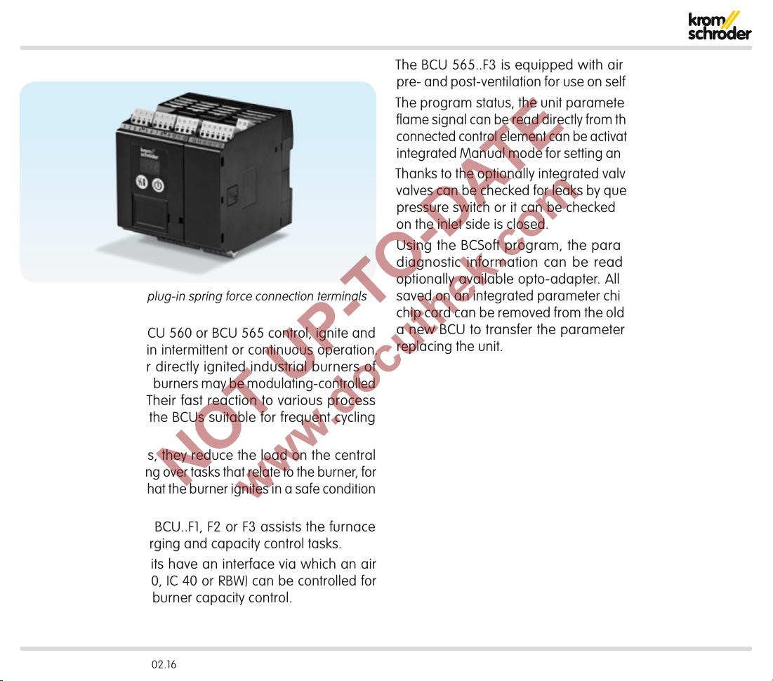
Burner control unit with plug-in spring force connection terminals
Burner control units BCU 560 or BCU 565 control, ignite and
monitor gas burners in intermittent or continuous operation.
They can be used for directly ignited industrial burners of
unlimited capacity. The burners may be modulating-controlled
or stage-controlled. Their fast reaction to various process
requirements makes the BCUs suitable for frequent cycling
operation.
On industrial furnaces, they reduce the load on the central
furnace control by taking over tasks that relate to the burner, for
example they ensure that the burner ignites in a safe condition
when it is restarted.
The air control on the BCU..F1, F2 or F3 assists the furnace
control for cooling, purging and capacity control tasks.
The burner control units have an interface via which an air
valve or actuator (IC20, IC40 or RBW) can be controlled for
staged or modulating burner capacity control.
The BCU 565..F3 is equipped with air flow monitoring and
pre- and post-ventilation for use on self recuperative burners.
The program status, the unit parameters and the level of the
flame signal can be read directly from the unit. The burner or a
connected control element can be activated manually using the
integrated Manual mode for setting and diagnostic purposes.
Thanks to the optionally integrated valve proving system, the
valves can be checked for leaks by querying an external gas
pressure switch or it can be checked whether the gas valve
on the inlet side is closed.
Using the BCSoft program, the parameters, analysis and
diagnostic information can be read from a BCU via the
optionally available opto-adapter. All valid parameters are
saved on an integrated parameter chip card. The parameter
chip card can be removed from the old unit and inserted into
a new BCU to transfer the parameters, for example when
replacing the unit.
BCU 560, BCU 565 · Edition 02.16 5
Page 6
Application
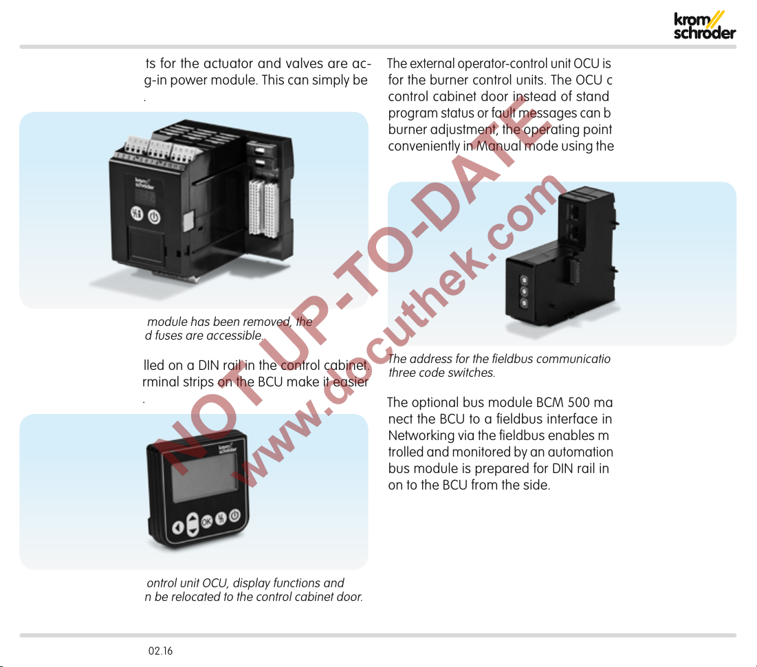
The monitored outputs for the actuator and valves are ac-
commodated in a plug-in power module. This can simply be
replaced if necessary.
Once the plug-in power module has been removed, the
parameter chip card and fuses are accessible.
The BCU can be installed on a DIN rail in the control cabinet.
Plug-in connection terminal strips on the BCU make it easier
to install and remove.
The external operator-control unitOCU is available as an option
for the burner control units. The OCU can be installed in the
control cabinet door instead of standard control units. The
program status or fault messages can be read on the OCU. For
burner adjustment, the operating points can be approached
conveniently in Manual mode using the operator-control unit.
The address for the fieldbus communication is set using
three code switches.
The optional bus module BCM500 makes it possible to con-
nect the BCU to a fieldbus interface in a PROFINET network.
Networking via the fieldbus enables multiple BCUs to be controlled and monitored by an automation system (e.g.PLC). The
bus module is prepared for DIN rail installation. It is pushed
on to the BCU from the side.
Thanks to the operator-control unitOCU, display functions and
operation of the BCU can be relocated to the control cabinet door.
BCU 560, BCU 565 · Edition 02.16 6
Page 7

Application
FCU 500
HT
P
Process control (PCC)
ϑ
A
1 2 3
38371817
BCU 565..F3
46
µC
49
50
47
V1 V2
VG
VG..L
PLC
VMV
ECOMAX
41
42
13
14
9
10
VR..R
TZI/TGI
PDZ
DG
1.1 Examples of application
1.1.1 Single-stage-controlled burner
Control: ON/OFF.
The gas/air mixture is adjusted to the requirements of the
applications using the parameters of pre-ventilation and post-
ventilation. The pressure switch monitors the air flow in the air
supply line or in the flue gas exhaust.
BCU 560, BCU 565 · Edition 02.16 7
Page 8
Application > Examples of application
Process control (PCC)
FCU 500
HT
P
ϑ
38371817
BCU 560..C0F3
46
µC
49
50
10
1 2 3
PLC
A
41
42
13
14
9
7
V1 V2
VAS VAG
VR..L
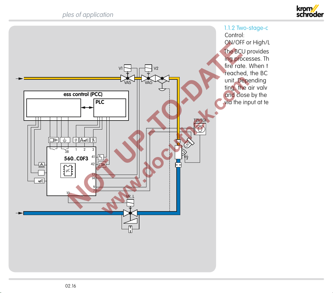
1.1.2 Two-stage-controlled burner
Control:
ON/OFF or High/Low
The BCU provides the cooling and purg-
ing processes. The burner starts at lowfire rate. When the operating state is
reached, the BCU advises the control
unit. Depending on the parameter setting, the air valve is actuated to open
and close by the program or externally
via the input at terminal 2.
TZI/TGI
UVS
BCU 560, BCU 565 · Edition 02.16 8
Page 9
Application > Examples of application
Process control (PCC)
FCU 500
DI
P
ϑ
38371817
BCU 560..C0F1
46
µC
49
50
52 53 54 55 56
1 2 3
PLC
A
41
42
13
14
15
9
7
V1
VAS VAG
VAS 1
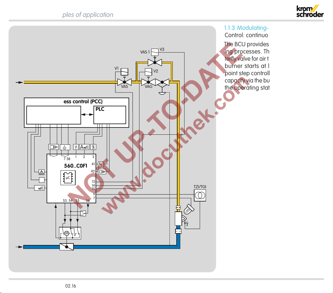
1.1.3 Modulating-controlled burner
Control: continuous
V3
The BCU provides the cooling and purg-
ing processes. The BCU moves the butterfly valve for air to ignition position. The
V2
burner starts at low-fire rate, a threepoint step controller controls the burner
capacity via the butterfly valve for air after
the operating state has been signalled.
TZI/TGI
UVS
M
BCU 560, BCU 565 · Edition 02.16 9
Page 10
Application > Examples of application
FCU 500..H1
M
HT
18
HT
HT
BCU 56x..D
49
5
µC
BCU 56x..D
49
5
µC
5-8
STM
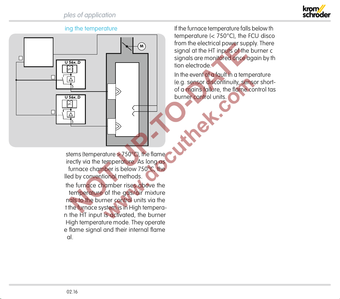
1.1.4 Flame control using the temperature
In high temperature systems (temperature >750°C), the flame
may be controlled indirectly via the temperature. As long as
the temperature in the furnace chamber is below 750°C, the
flame must be controlled by conventional methods.
If the temperature in the furnace chamber rises above the
spontaneous ignition temperature of the gas/air mixture
(>750°C), the FCU signals to the burner control units via the
fail-safe HT output that the furnace system is in High tempera-
ture mode (HT). When the HT input is activated, the burner
control units switch to High temperature mode. They operate
without evaluating the flame signal and their internal flame
control is non-functional.
If the furnace temperature falls below the spontaneous ignition
temperature (<750°C), the FCU disconnects the HToutput
from the electrical power supply. There is no longer an active
signal at the HT inputs of the burner control units. The flame
signals are monitored once again by the UV sensor or ionization electrode.
In the event of a fault in a temperature monitoring component
(e.g. sensor discontinuity, sensor short-circuit) or in the event
of a mains failure, the flame control task is transferred to the
burner control units.
BCU 560, BCU 565 · Edition 02.16 10
Page 11
Application > Examples of application
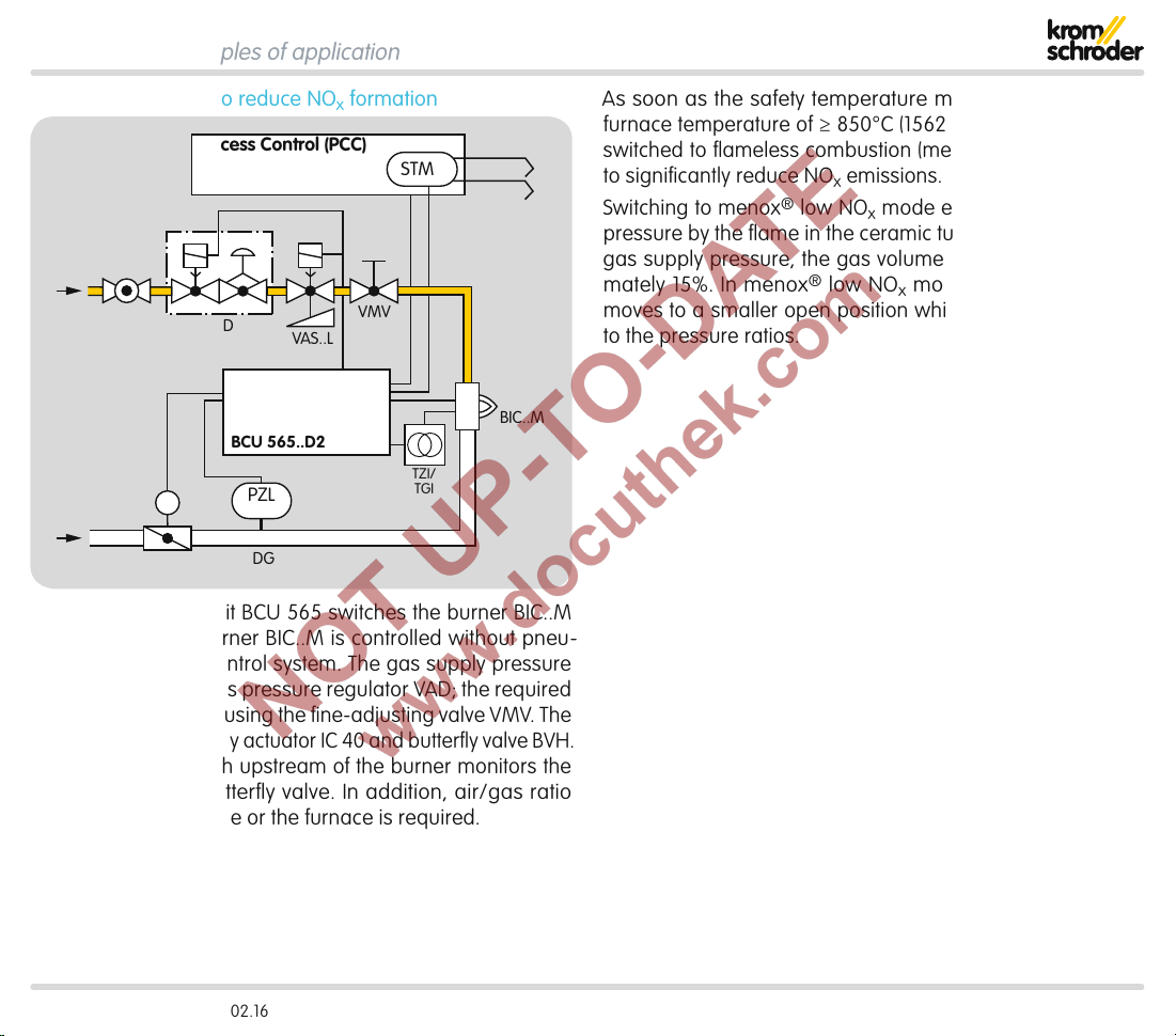
1.1.5 menox® mode to reduce NOx formation
Process Control (PCC)
STM
AKT
M
IC 40 + BVH
VAD
BCU 565..D2
PZL
VAS..L
DG
VMV
TZI/
TGI
BIC..M
The burner control unit BCU 565 switches the burner BIC..M
ON/OFF in cycles. Burner BIC..M is controlled without pneu-
matic air/gas ratio control system. The gas supply pressure
is controlled by the gas pressure regulatorVAD; the required
burner capacity is set using the fine-adjusting valveVMV. The
capacity is controlled by actuator IC40 and butterfly valveBVH.
An air pressure switch upstream of the burner monitors the
functioning of the butterfly valve. In addition, air/gas ratio
monitoring for the zone or the furnace is required.
As soon as the safety temperature monitor STM signals a
furnace temperature of ≥850°C(1562°F), the burner can be
switched to flameless combustion (menox® low NOx mode)
to significantly reduce NOx emissions.
Switching to menox
®
low NOx mode eliminates the counterpressure by the flame in the ceramic tubeTSC. At a constant
gas supply pressure, the gas volume increases by approximately15%. In menox® low NOx mode, the butterfly valve
moves to a smaller open position which has been adapted
to the pressure ratios.
BCU 560, BCU 565 · Edition 02.16 11
Page 12
Application > Examples of application
1
2 3
BCU 56x
BCM
BCU 56x
BCM
BCU 56x
BCM
PROFINET
L1
BUS
FCU
P
HT
PLC
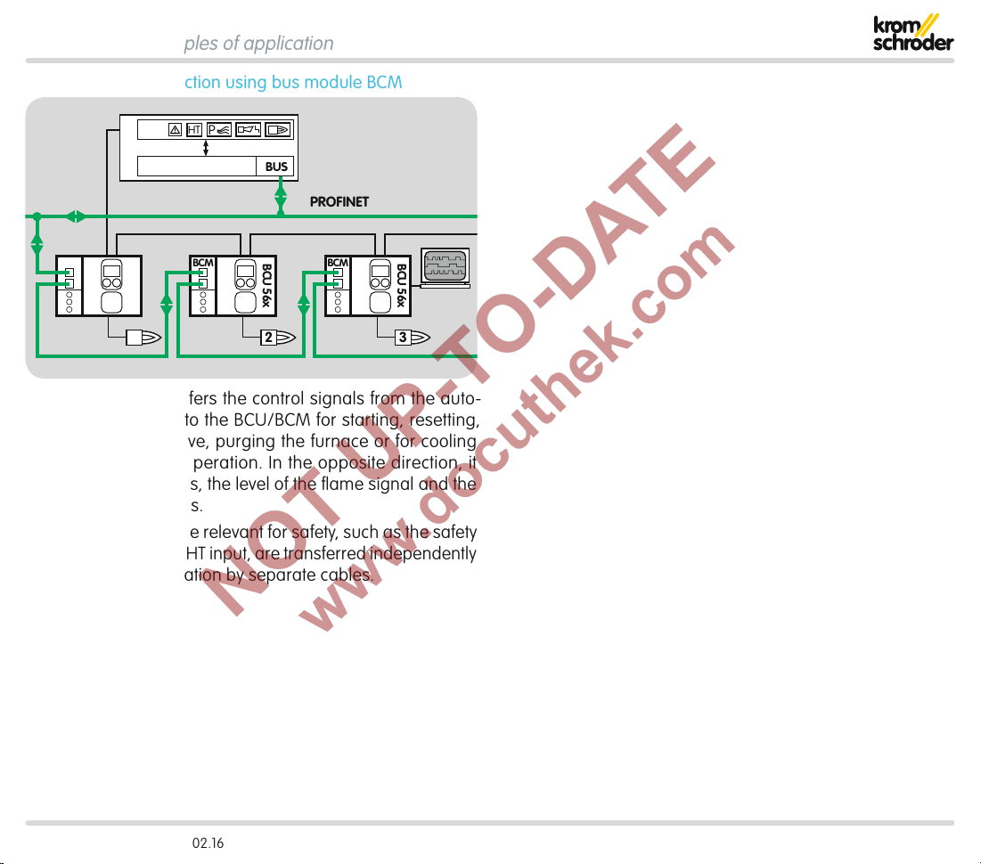
1.1.6 PROFINET connection using bus module BCM
The bus system transfers the control signals from the auto-
mation system (PLC) to the BCU/BCM for starting, resetting,
controlling the air valve, purging the furnace or for cooling
and heating during operation. In the opposite direction, it
sends operating status, the level of the flame signal and the
current program status.
Control signals that are relevant for safety, such as the safety
interlocks, purge and HT input, are transferred independently
of the bus communication by separate cables.
BCU 560, BCU 565 · Edition 02.16 12
Page 13
Application > Examples of application
PZL PZH PZ
45
P
>750°
47 4858
DL
minDLPurge
PZL PDZ
DG DG
VAS
VAS
pu/2
DG DG DG
DG
46
1
ϑ
2
3
min
49 15 131450
DG
max
µC
FCU 500..F0
STM
M
VAS
BCU 560..F3
BCU 560..F3
VCG
VR..L
VCG
VR..L
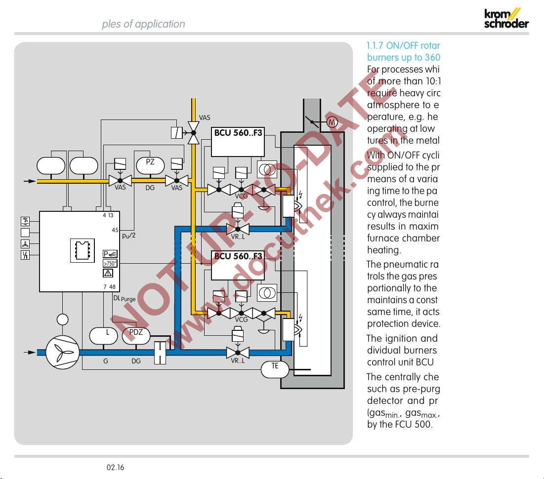
1.1.7 ON/OFF rotary impulse control for
burners up to 360kW
For processes which require a turndown
of more than 10:1 and/or those which
require heavy circulation of the furnace
atmosphere to ensure a uniform tem-
M
perature, e.g. heat treatment furnaces
operating at low and medium temperatures in the metallurgical industry.
With ON/OFF cyclic control, the capacity
supplied to the process is controlled by
means of a variable ratio of the operating time to the pause time. In this type of
control, the burner output pulse frequency always maintains full momentum and
results in maximum convection in the
furnace chamber, even with regulated
heating.
The pneumatic ratio control system con-
trols the gas pressure on the burner proportionally to the air pressure and thus
maintains a constant air/gas ratio. At the
same time, it acts as a low air pressure
protection device.
The ignition and monitoring of the in-
dividual burners is ensured by burner
TE
control unit BCU560.
The centrally checked safety functions
such as pre-purge, tightness test, flow
detector and pressure switch check
(gas
min.
, gas
max.
, air
) are provided
min.
by the FCU500.
BCU 560, BCU 565 · Edition 02.16 13
Page 14

Application > Examples of application
PZL PZH PZ
DG DG DG
min
49 15 131450
DG
max
µC
DG
1
ϑ
2
3
FCU 500..F1
STM
DL
minDLPurge
M
PZL PDZ
VAS
pu/2
45
P
57
16
>750°
TC
0°➔90°
53
90°➔0°
54
55
47 4858
VAS
M
VAS
BCU 560..F0
66
BCU 560..F0
66
VCG
VCG
1.1.8 Modulating burner control
For processes that do not require heavy
circulation in the furnace, e.g. aluminium
smelting furnaces.
This system is suitable for processes in
which infiltrated air may flow into the
M
furnace through switched off burners.
The capacity can be adjusted continu-
ously by activating the control element
(analogue or 3-point step signal). The
pneumatic ratio control system controls
the gas pressure proportionally to the air
pressure and thus maintains a constant
air/gas ratio. At the same time, it acts
as a low air pressure protection device.
One burner control unit per burner is
required for ignition and monitoring.
The centrally checked safety functions
such as pre-purge, setting the valve
to ignition position via a butterfly valve
control system, tightness test, flow detector and pressure switch check (gas
gas
max.
, air
) are provided by the
min.
min.
,
FCU500.
DGDG
TE
BCU 560, BCU 565 · Edition 02.16 14
Page 15
2 Certification
Certified to SIL and PL
For systems up to SIL 3 pursuant to EN 61508 and PL e pursu-
ant to ISO 13849
EU certified pursuant to
– Gas Appliances Directive (2009/142/EC)
Meets the requirements of the
– Low Voltage Directive (2006/95/EC),
– EMC Directive (2004/108/EC).
FM approved
Factory Mutual Research Class: 7400 Process Control Valves.
Designed for applications pursuant to NFPA 85 and NFPA 86.
www.approvalguide.com
Eurasian Customs Union
The products BCU 560 and BCU 565 meet the technical speci-
fications of the Eurasian Customs Union.
BCU 560, BCU 565 · Edition 02.16 15
Page 16
3 Function
3.1 Connection diagram
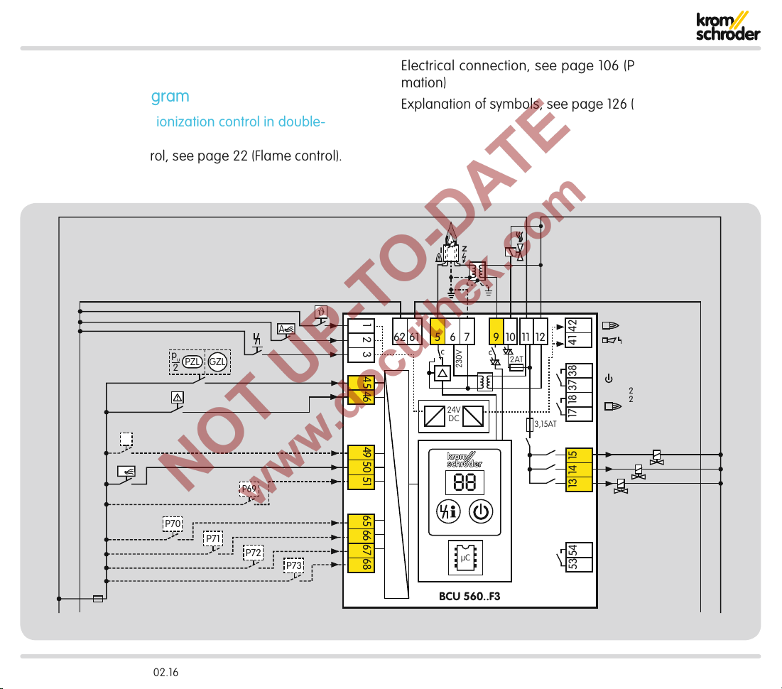
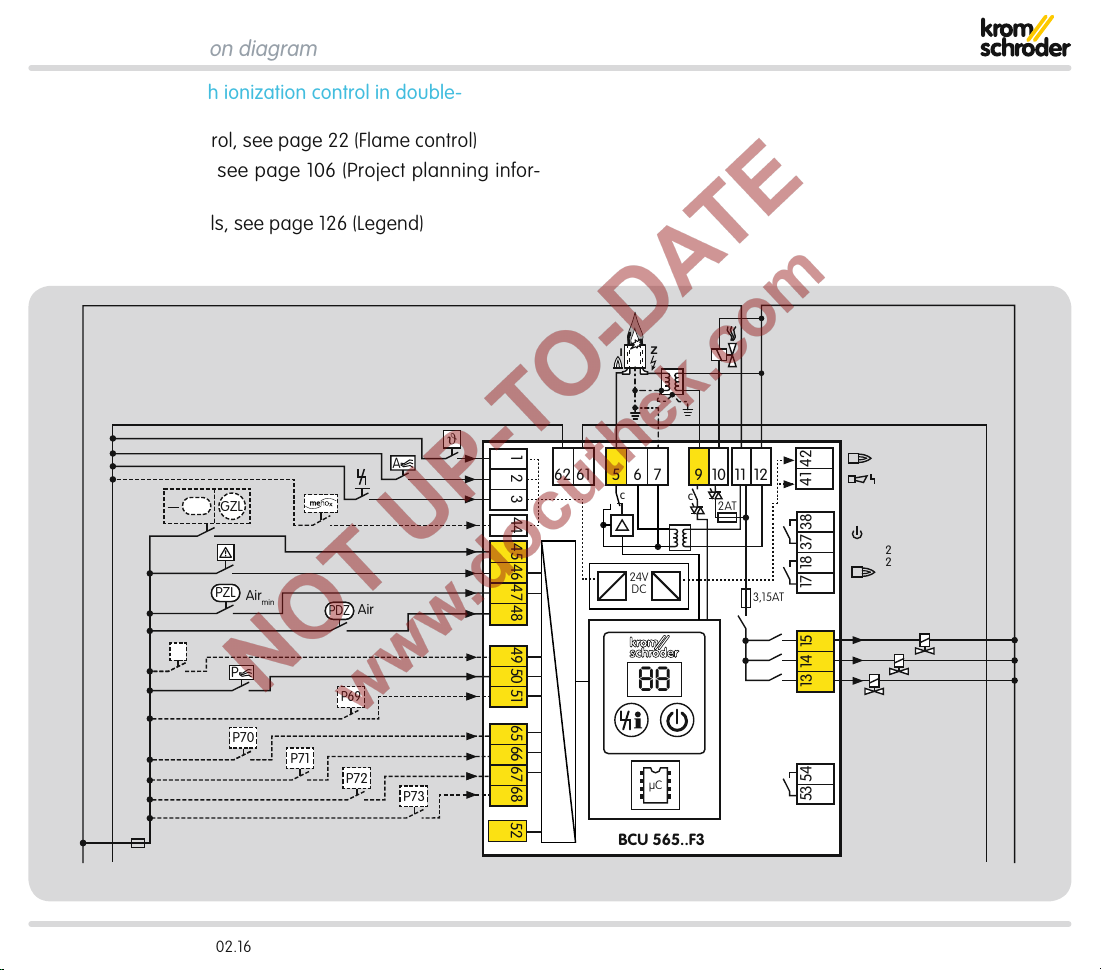
3.1.1 BCU560..F3 with ionization control in double-
electrode operation
Alternative flame control, see page22 (Flame control).
Electrical connection, see page106 (Project planning information)
Explanation of symbols, see page126 (Legend)
Z
I
HT
P
0,6 × I
ϑ
A
p
u
PZL
GZL
2
P69
P70
P70
P72P71
P72P72
P73
N
1 2 3 4645 65 66 67 6849 50 51
5 6 9 11
61
c
24V
DC
c
230V
2AT
1210762
3,15AT
41 42
17 18 37 38
max. 1 A;
24
V
DC,
250 V AC
V3
88
µC
13 14 15
53 54
V2
V1
BCU 560..F3
0 V+24 V
NL1
BCU 560, BCU 565 · Edition 02.16 16
Page 17
Function > Connection diagram
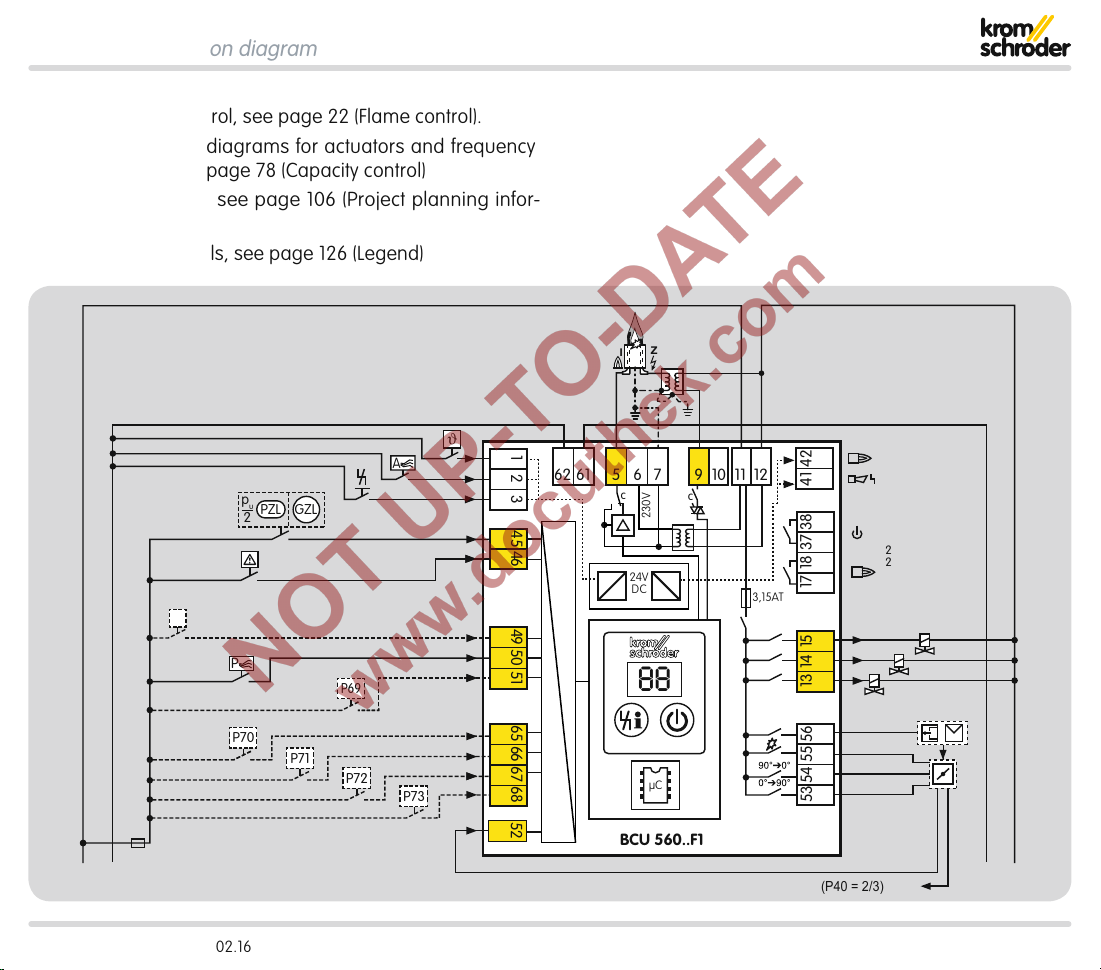
3.1.2 BCU560..F1
Alternative flame control, see page22 (Flame control).
Detailed connection diagrams for actuators and frequency
converters, see from page78 (Capacity control)
Electrical connection, see page106 (Project planning infor-
mation)
Explanation of symbols, see page126 (Legend)
Z
I
ϑ
A
p
u
PZL
GZL
2
HT
P
P69
P70
P70
P72P71
P72P72
P73
1 2 3 4645 65 66 67 6849 50 51
5 6 9 11
61
c
24V
DC
c
230V
1210762
3,15AT
41 42
17 18 37 38
max. 1 A;
24
V
DC,
250 V AC
V3
88
µC
13 14 15
53 54 55 56
V2
V1
mA
52
0,6 × I
N
BCU 560..F1
(P40 = 2/3) => 51
0 V+24 V
NL1
BCU 560, BCU 565 · Edition 02.16 17
Page 18
Function > Connection diagram
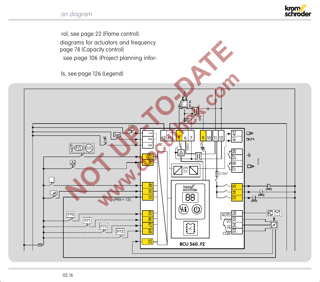
3.1.3 BCU560..F2
Alternative flame control, see page22 (Flame control).
Detailed connection diagrams for actuators and frequency
converters, see from page78 (Capacity control)
Electrical connection, see page106 (Project planning infor-
mation)
Explanation of symbols, see page126 (Legend)
Z
I
HT
P
0,6 × I
ϑ
A
p
u
PZL
GZL
2
(P69 = 13)
P70P70
P72P71
P72P72
P73
N
1 2 3 4645 65 66 67 6849 50 51
52
5 6 9 11
61
c
230V
24V
DC
88
µC
BCU 560..F2
1210762
3,15AT
41 42
17 18 37 38
max. 1 A;
24 V DC,
250 V AC
c
V3
V2
V1
mA
0 V+24 V
NL1
AUTO
LO
COM
13 14 15
HI
53 54 55 56
BCU 560, BCU 565 · Edition 02.16 18
Page 19
Function > Connection diagram
3.1.4 BCU565..F3 with ionization control in double-
electrode operation
Alternative flame control, see page22 (Flame control)
Electrical connection, see page106 (Project planning infor-
mation)
Explanation of symbols, see page126 (Legend)
Z
I
ϑ
A
p
u
PZL
GZL
2
PZL
PZL
Air
min
HT
P
P70P70
P72P71
PDZ
PDZ
Air
P69
P72P72
P73
1 2 3
44
4645 4847 65 66 67 6849 50 51
5 6 9 11
62 61
c
24V
DC
88
7
c
2AT
1210
3,15AT
41 42
17 18 37 38
max. 1 A;
24 V DC,
250 V AC
V3
13 14 15
µC
53 54
V2
V1
52
0.6 × I
N
L1
BCU 565..F3
0 V+24 V
N
BCU 560, BCU 565 · Edition 02.16 19
Page 20
Function > Connection diagram
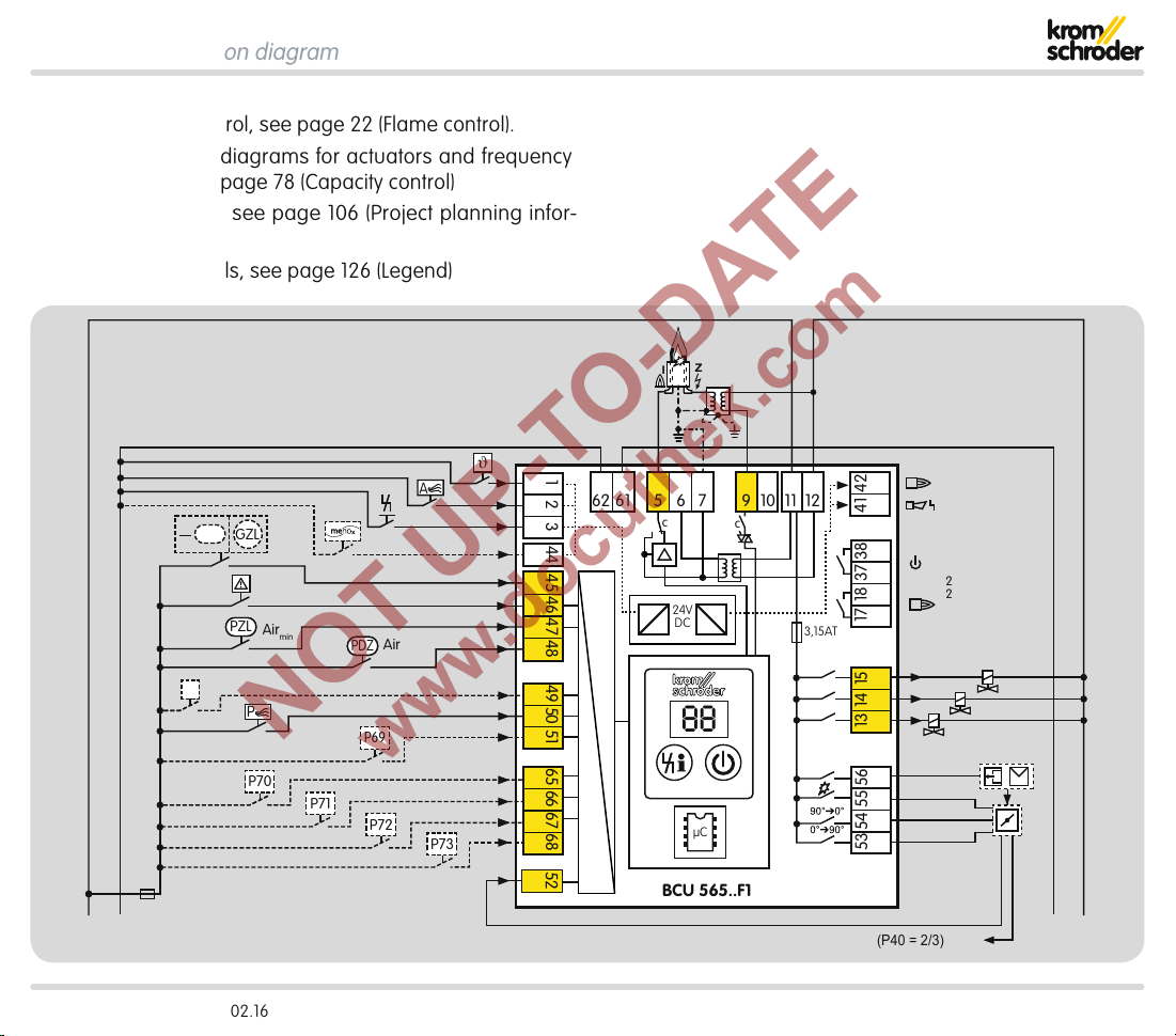
3.1.5 BCU565..F1
Alternative flame control, see page22 (Flame control).
Detailed connection diagrams for actuators and frequency
converters, see from page78 (Capacity control)
Electrical connection, see page106 (Project planning infor-
mation)
Explanation of symbols, see page126 (Legend)
Z
I
ϑ
A
p
u
PZL
GZL
2
PZL
PZL
Air
min
HT
P
P70P70
P72P71
PDZ
PDZ
Air
P69
P72P72
P73
1 2 3 4645 4847 65 66 67 6849 50 51
44
5 6 9 11
62 61
c
24V
DC
88
7
c
1210
3,15AT
41 42
17 18 37 38
max. 1 A;
24 V DC,
250 V AC
V3
13 14 15
µC
53 54 55 56
V2
V1
mA
52
0.6 × I
N
L1
BCU 565..F1
(P40 = 2/3) => 51
0 V+24 V
N
BCU 560, BCU 565 · Edition 02.16 20
Page 21
Function > Connection diagram
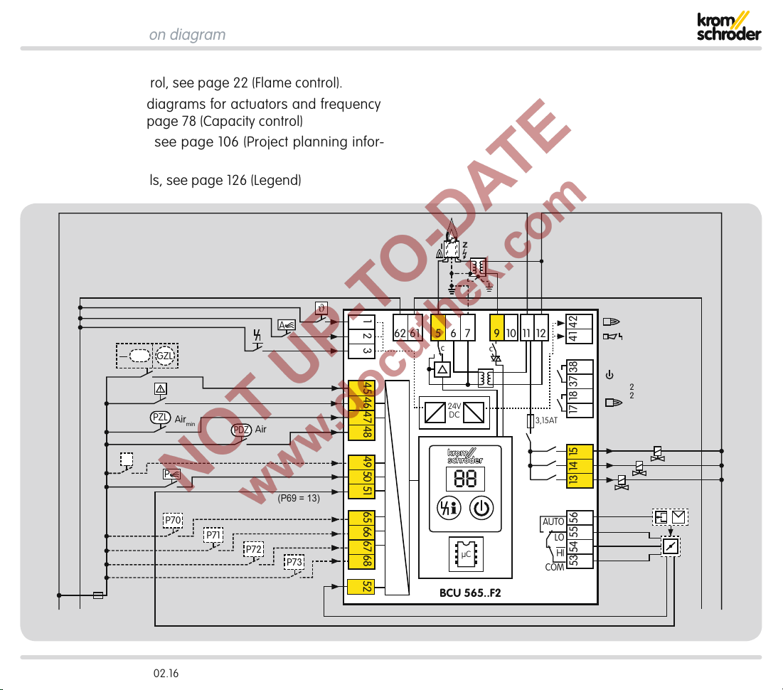
3.1.6 BCU565..F2
Alternative flame control, see page22 (Flame control).
Detailed connection diagrams for actuators and frequency
converters, see from page78 (Capacity control)
Electrical connection, see page106 (Project planning infor-
mation)
Explanation of symbols, see page126 (Legend)
Z
I
ϑ
A
p
u
PZL
GZL
2
PZL
PZL
Air
HT
0.6 × I
min
P
P70P70
P72P71
N
PDZ
PDZ
Air
(P69 = 13)
P72P72
P73
L1
1 2 3 4645 4847 65 66 67 6849 50 51
52
5 6 9 11
62 61
7
c
24V
DC
c
88
µC
BCU 565..F2
1210
3,15AT
AUTO
COM
41 42
max. 1 A;
24 V DC,
250 V AC
17 18 37 38
V3
13 14 15
LO
HI
53 54 55 56
V2
V1
mA
0 V+24 V
N
BCU 560, BCU 565 · Edition 02.16 21
Page 22
Function > Connection diagram
1 2 3 4645 65 66 67 6849 50 51
41 42
5 6 9 11
1210762
61
Z
NL1
1 2 3 4645 65 66 67 6849 50 51
41 42
5 6 9 11
1210762
61
UVS
1
2
3
Z
NL1
1 2 3 4645 65 66 67 6849 50 51
41 42
5 6 9 11
1210762
61
ϑ
0 V
24 V
+–
0–20 mA
UVD1
1
2
4
3
5
6
Z
NL1
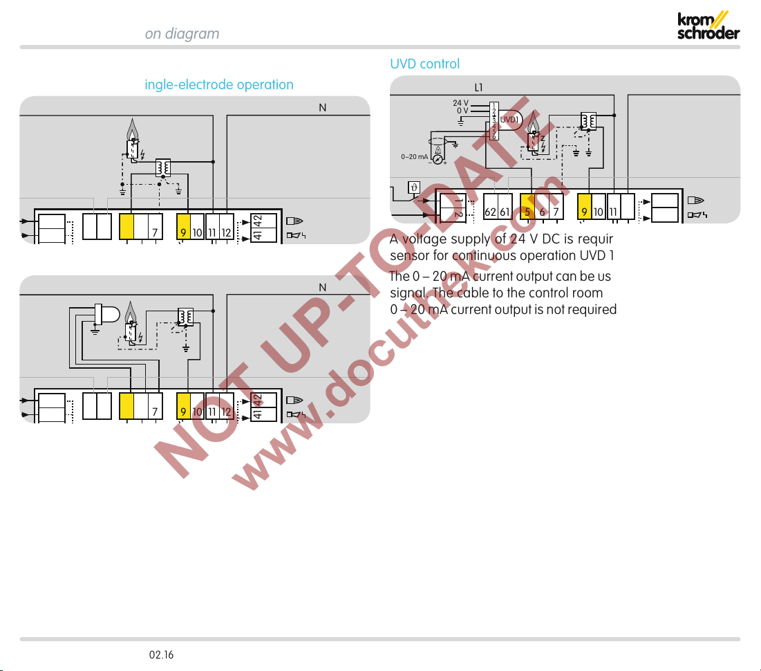
3.1.7 Flame control Ionization control in single-electrode operation
UVS control
UVD control
A voltage supply of 24 VDC is required to operate the UV
sensor for continuous operation UVD1.
The 0 – 20mA current output can be used to display the flame
signal. The cable to the control room must be screened. The
0 – 20mA current output is not required for normal operation.
BCU 560, BCU 565 · Edition 02.16 22
Page 23
Function
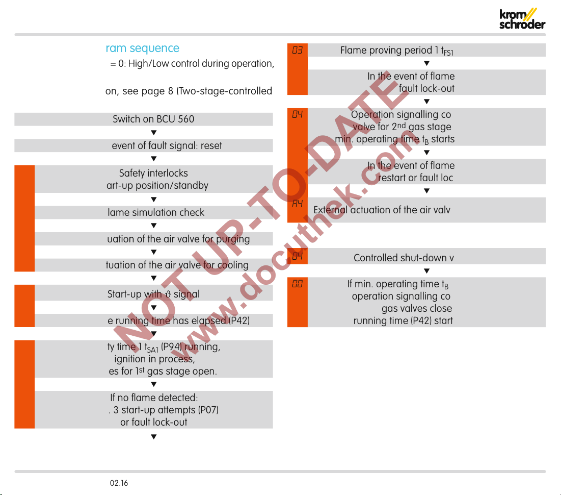
3.2 BCU 560 program sequence
Parameters 48 and 49 = 0: High/Low control during operation,
cooling in standby
Example of application, see page8 (Two-stage-controlled
burner)
Switch on BCU 560
▼
In the event of fault signal: reset
▼
00
P0
A0
H1
02
External actuation of the air valve for purging
External actuation of the air valve for cooling
Wait until the running time has elapsed (P42)
Safety interlocks
Start-up position/standby
▼
Flame simulation check
▼
▼
▼
Start-up with ϑ signal
▼
▼
Safety time 1 t
(P94) running,
SA1
ignition in process,
valves for 1st gas stage open.
▼
If no flame detected:
max. 3 start-up attempts (P07)
or fault lock-out
▼
03
Flame proving period 1 t
FS1
▼
running (P95)
In the event of flame failure:
fault lock-out
▼
04
Operation signalling contact closes,
valve for 2nd gas stage opens and
min. operating time tB starts to elapse (P61)
▼
In the event of flame failure:
restart or fault lock-out
▼
A4
External actuation of the air valve for capacity control
04
00
Controlled shut-down via ϑ signal
▼
If min. operating time tB has elapsed:
operation signalling contact opens,
gas valves close and
running time (P42) starts to elapse
BCU 560, BCU 565 · Edition 02.16 23
Page 24
Function
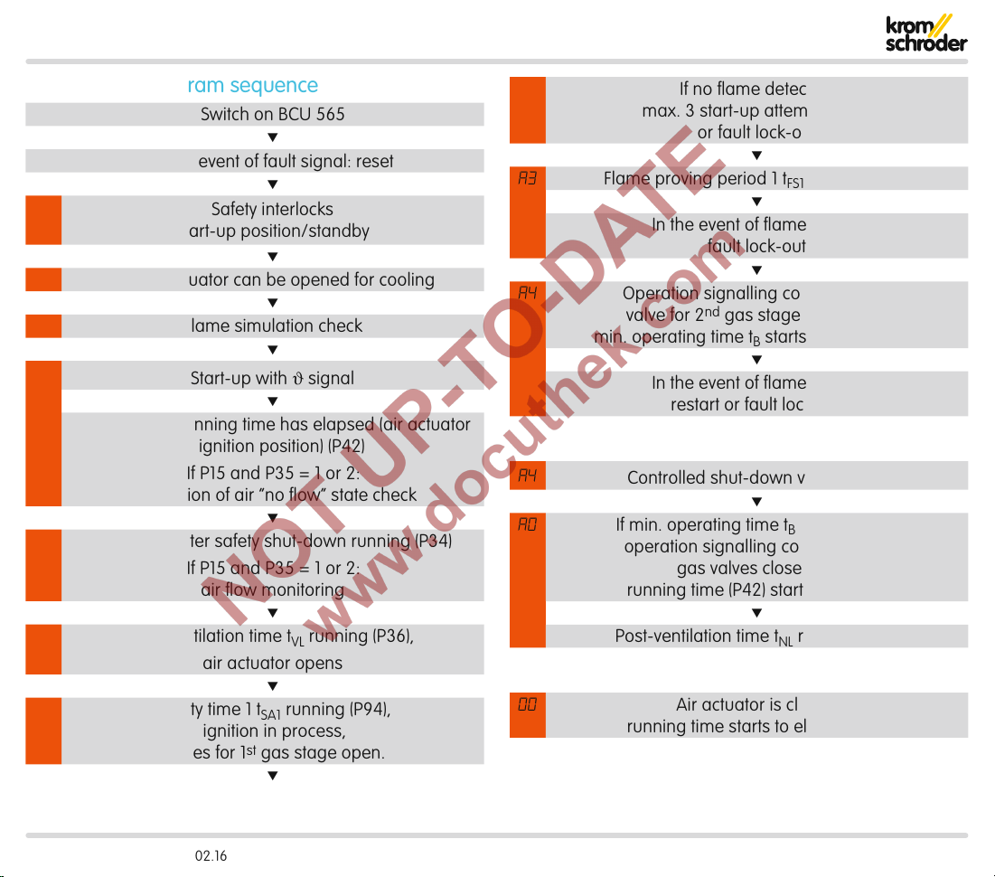
3.3 BCU 565 program sequence
Switch on BCU 565
▼
In the event of fault signal: reset
▼
00
A0
The air actuator can be opened for cooling
00
H1
Wait until the running time has elapsed (air actuator
verification of air “no flow” state check
P1
A1
Pre-purge after safety shut-down running (P34)
Pre-ventilation time tVL running (P36),
A2
Safety interlocks
Start-up position/standby
▼
▼
Flame simulation check
▼
Start-up with ϑ signal
▼
in ignition position) (P42)
If P15 and P35 = 1 or 2:
▼
If P15 and P35 = 1 or 2:
air flow monitoring
▼
air actuator opens
▼
Safety time 1 t
running (P94),
SA1
ignition in process,
valves for 1st gas stage open.
▼
A3
A4
A4
A0
00
If no flame detected:
max. 3 start-up attempts (P07)
or fault lock-out
▼
Flame proving period 1 t
FS1
▼
running (P95)
In the event of flame failure:
fault lock-out
▼
Operation signalling contact closes,
valve for 2nd gas stage opens and
min. operating time tB starts to elapse (P61)
▼
In the event of flame failure:
restart or fault lock-out
Controlled shut-down via ϑ signal
▼
If min. operating time tB has elapsed:
operation signalling contact opens,
gas valves close and
running time (P42) starts to elapse
▼
Post-ventilation time tNL running (P39)
Air actuator is closed,
running time starts to elapse (P42)
BCU 560, BCU 565 · Edition 02.16 24
Page 25
4 Air control
M
PZL PZH PZ
PZL PDZ
TE
M
FCU 500..F0
µC
P
DG DG DG
VAS
VAS
VCG
VCG
VR..L
VR..L
DG DG
DG
minDGmax
49 15 131450
45
47 4858
>750°
pu/2
DL
minDLPurge
BCU 5xx..F3
BCU 5xx..F3
ϑ
1
46
2
3
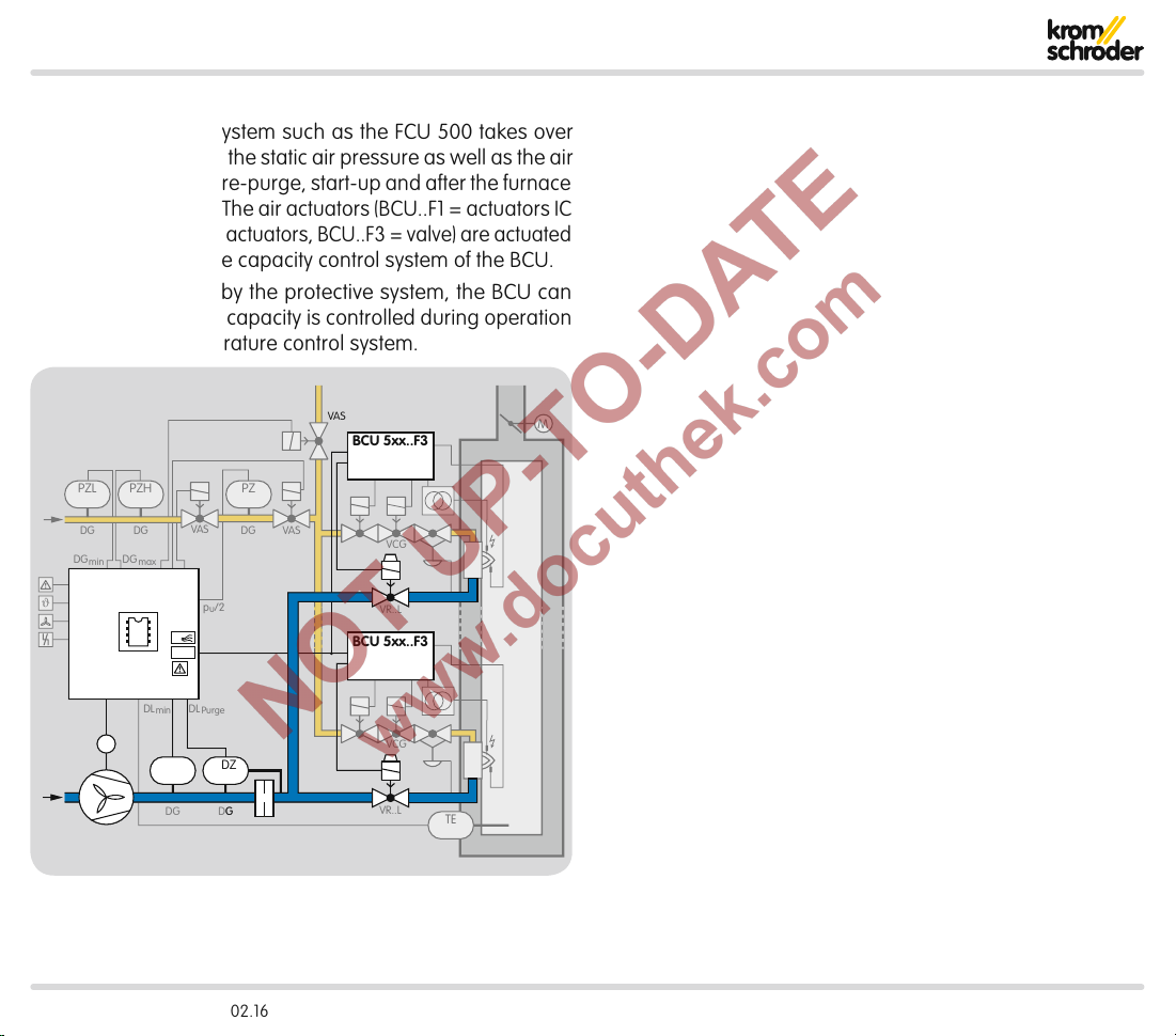
A central protective system such as the FCU500 takes over
air control. It monitors the static air pressure as well as the air
volume required for pre-purge, start-up and after the furnace
has been shut down. The air actuators (BCU..F1 = actuators IC
20/40, BCU..F2 = RBW actuators, BCU..F3 = valve) are actuated
for this purpose by the capacity control system of the BCU.
After being enabled by the protective system, the BCU can
start the burners. The capacity is controlled during operation
by an external temperature control system.
VAS
BCU 5xx..F3
49 15 131450
46
1
2
3
FCU 500
M
µC
P
>750°
DL
minDLPurge
PZL PDZ
DG DG
45
BCU 5xx..F3
BCU 560, BCU 565 · Edition 02.16 25
Page 26
Air control
BCU 560..C0F1
µC
VAS VAG
TZI/TGI
V1
V2
V3
14
15
13
9
7
UVS
38371817
1 2 3
46
49
50
41
42
M
52 53 54 55 56
VAS 1
Process control (PCC)
ϑ
A
P
DI
FCU 500
SPS
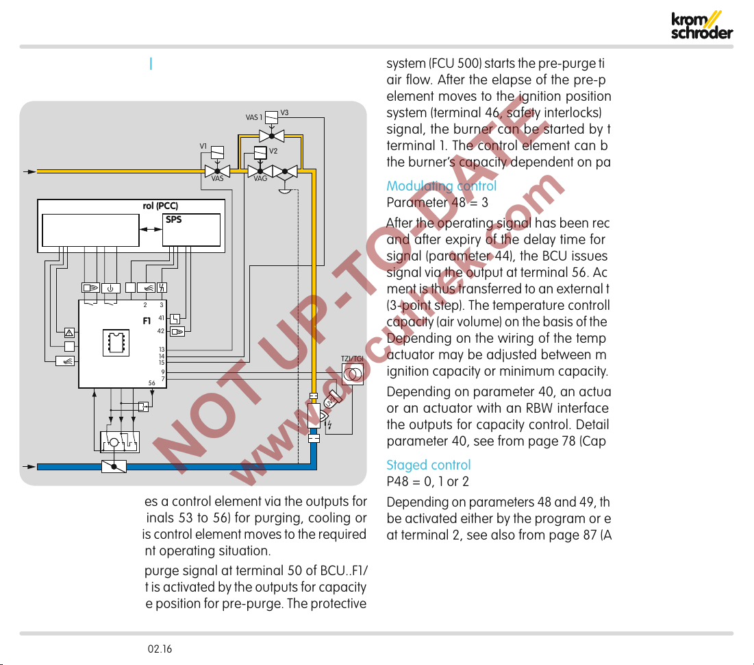
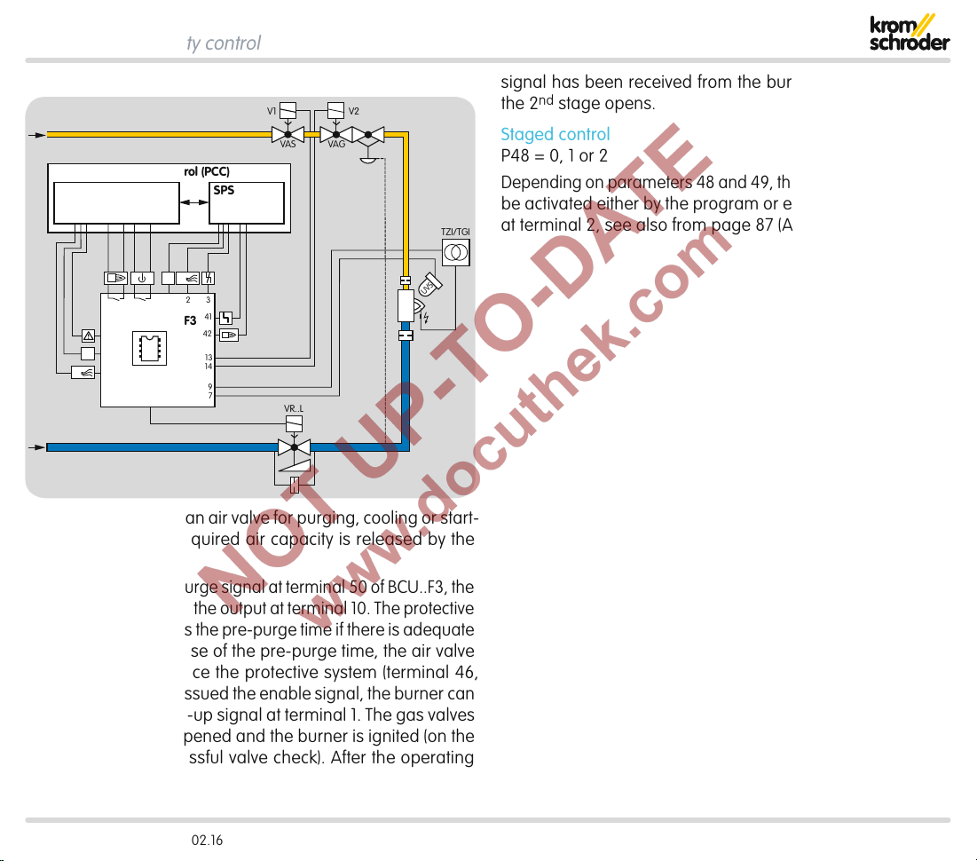
4.1 Capacity control
4.1.1 BCU..F1/F2
system (FCU 500) starts the pre-purge time if there is adequate
air flow. After the elapse of the pre-purge time, the control
element moves to the ignition position. Once the protective
system (terminal 46, safety interlocks) has issued the enable
signal, the burner can be started by the start-up signal at
terminal 1. The control element can be activated to control
the burner’s capacity dependent on parameters 48 and 49.
Modulating control
Parameter 48 = 3
After the operating signal has been received from the burner
and after expiry of the delay time for the controller enable
signal (parameter 44), the BCU issues the controller enable
signal via the output at terminal 56. Access to the control element is thus transferred to an external temperature controller
(3-point step). The temperature controller controls the burner
capacity (air volume) on the basis of the required temperature.
Depending on the wiring of the temperature controller, the
actuator may be adjusted between maximum capacity and
ignition capacity or minimum capacity.
Depending on parameter40, an actuator IC20, IC40, IC50
or an actuator with an RBW interface can be actuated via
the outputs for capacity control. Detailed information about
parameter 40, see from page78 (Capacity control).
The BCU..F1/F2 activates a control element via the outputs for
capacity control (terminals 53 to56) for purging, cooling or
starting the burner. This control element moves to the required
position for the relevant operating situation.
As soon as there is a purge signal at terminal 50 of BCU..F1/
F2, the control element is activated by the outputs for capacity
Staged control
P48 = 0, 1 or 2
Depending on parameters 48 and 49, the control element may
be activated either by the program or externally via the input
at terminal 2, see also from page87 (Air actuator control).
control to approach the position for pre-purge. The protective
BCU 560, BCU 565 · Edition 02.16 26
Page 27
Air control > Capacity control
BCU 560..C0F3
µC
VAS VA G
TZI/TGI
VR..L
V1 V2
14
13
9
7
10
UVS
38371817
1 2 3
FCU 500
Process control (PCC)
46
49
50
P
HT
ϑ
41
42
A
SPS
4.1.2 BCU..F3
The BCU..F3 activates an air valve for purging, cooling or start-
ing the burner. The required air capacity is released by the
air valve.
As soon as there is a purge signal at terminal 50 of BCU..F3, the
air valve is activated by the output at terminal 10. The protective
system (FCU 500) starts the pre-purge time if there is adequate
air flow. After the elapse of the pre-purge time, the air valve
closes for ignition. Once the protective system (terminal 46,
safety interlocks) has issued the enable signal, the burner can
be started by the start-up signal at terminal 1. The gas valves
for the 1st stage are opened and the burner is ignited (on the
BCU..C1 after a successful valve check). After the operating
signal has been received from the burner, the gas valve for
the 2ndstage opens.
Staged control
P48 = 0, 1 or 2
Depending on parameters 48 and 49, the control element may
be activated either by the program or externally via the input
at terminal 2, see also from page87 (Air actuator control).
BCU 560, BCU 565 · Edition 02.16 27
Page 28
5 menox® low NOx mode
▼
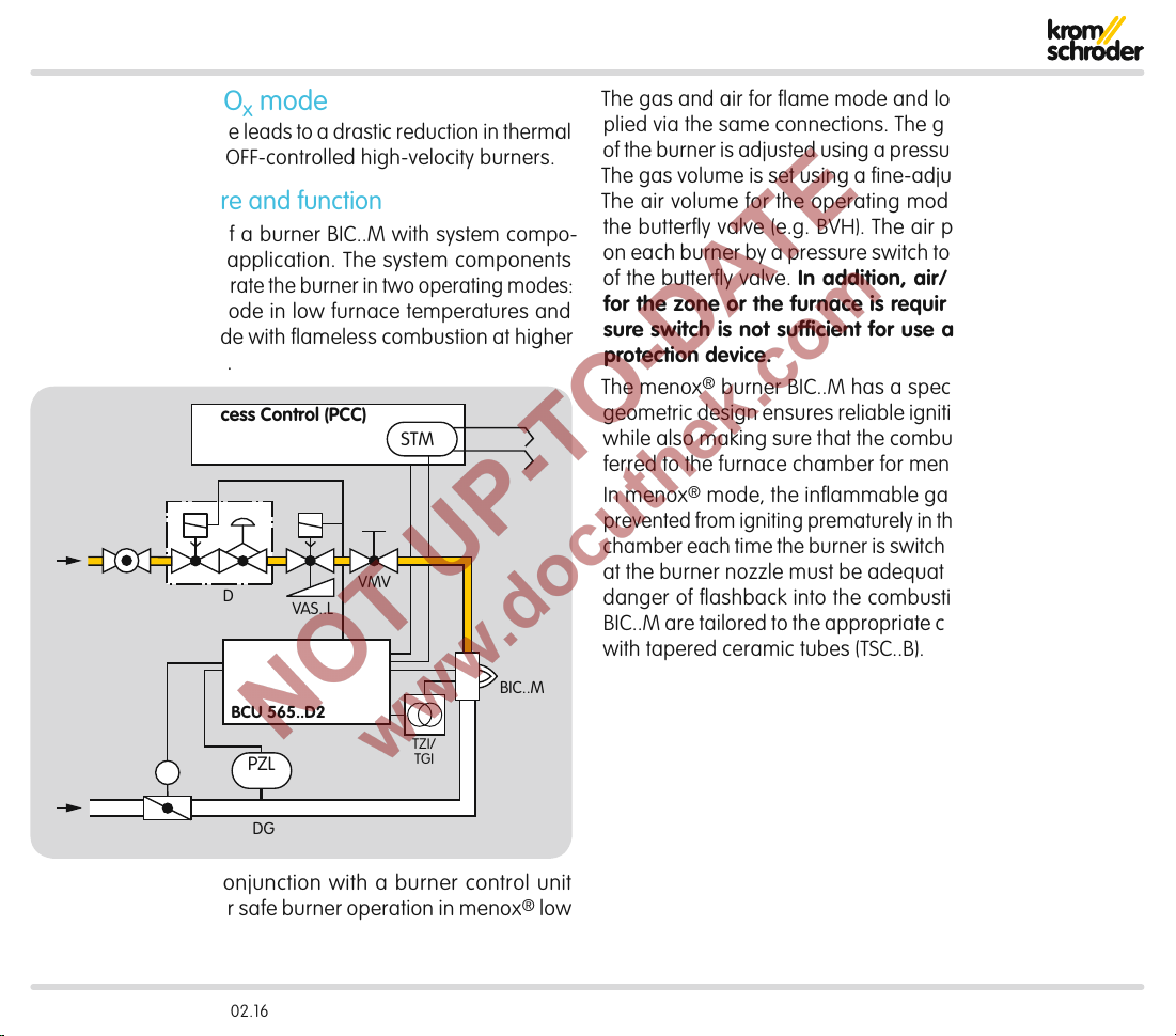
menox® low NOx mode leads to a drastic reduction in thermal
NOx formation in ON/OFF-controlled high-velocity burners.
5.1 System structure and function
The system consists of a burner BIC..M with system compo-
nents tailored to the application. The system components
make it possible to operate the burner in two operating modes:
conventional flame mode in low furnace temperatures and
menox® low NOx mode with flameless combustion at higher
furnace temperatures.
Process Control (PCC)
STM
AKT
VAD
M
VAS..L
BCU 565..D2
PZL
VMV
TZI/
TGI
BIC..M
The gas and air for flame mode and low NO
mode are sup-
x
plied via the same connections. The gas pressure upstream
of the burner is adjusted using a pressure regulator (e.g. VAD).
The gas volume is set using a fine-adjusting valve (e.g. VMV).
The air volume for the operating modes is set by adjusting
the butterfly valve (e.g. BVH). The air pressure is monitored
on each burner by a pressure switch to check the functioning
of the butterfly valve. In addition, air/gas ratio monitoring
for the zone or the furnace is required since the air pres-
sure switch is not sufficient for use as a low air pressure
protection device.
The menox
®
burner BIC..M has a special mixing unit whose
geometric design ensures reliable ignition and a stable flame
while also making sure that the combustion process is transferred to the furnace chamber for menox® mode.
In menox
®
mode, the inflammable gas/air mixture must be
prevented from igniting prematurely in the ceramic combustion
chamber each time the burner is switched on. The flow velocity
at the burner nozzle must be adequately high to prevent the
danger of flashback into the combustion chamber. Burners
BIC..M are tailored to the appropriate capacity and combined
with tapered ceramic tubes (TSC..B).
IC 40 + BVH
DG
A burner BIC..M in conjunction with a burner control unit
BCU..D2 is required for safe burner operation in menox® low
NOx mode.
BCU 560, BCU 565 · Edition 02.16 28
Page 29
menox® low NOx mode > System structure and function
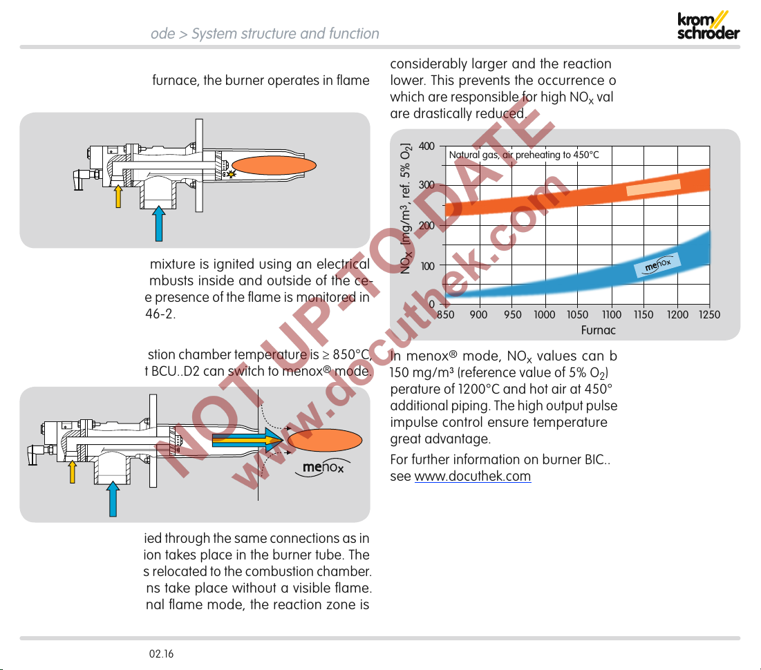
850 1050 1250120011501100900 1000950
0
100
200
300
400
Furnace temperature [°C]
NO
x
[mg/m
3
, ref. 5% O
2
]
Flame mode
Natural gas, air preheating to 450°C
Flame mode
In order to heat up the furnace, the burner operates in flame
mode.
The ignitable gas/air mixture is ignited using an electrical
ignition spark and combusts inside and outside of the ce-
ramic burner tube. The presence of the flame is monitored in
compliance with EN746-2.
®
menox
mode
As soon as the combustion chamber temperature is ≥ 850°C,
the burner control unit BCU..D2 can switch to menox® mode.
considerably larger and the reaction density considerably
lower. This prevents the occurrence of peak temperatures
which are responsible for high NOx values. Emissions of NOx
are drastically reduced.
In menox® mode, NOx values can be reduced to below
150mg/m³ (reference value of 5% O2) even at a furnace tem-
perature of 1200°C and hot air at 450°C– without expensive
additional piping. The high output pulse frequency and rotary
impulse control ensure temperature uniformity which is of
great advantage.
For further information on burner BIC..M,
see www.docuthek.com
Gas and air are supplied through the same connections as in
flame mode. No ignition takes place in the burner tube. The
combustion process is relocated to the combustion chamber.
The oxidation reactions take place without a visible flame.
Compared to traditional flame mode, the reaction zone is
BCU 560, BCU 565 · Edition 02.16 29
Page 30
menox® low NOx mode
38371817
1 2 3
46
50
41
44
42
ϑ
A
P
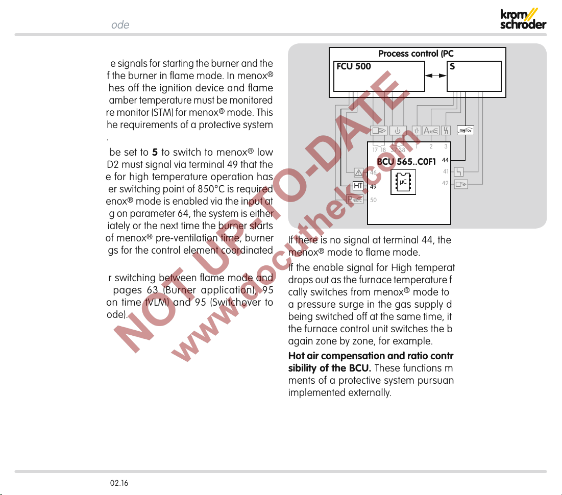
5.2 BCU..D2
The BCU coordinates the signals for starting the burner and the
fail-safe monitoring of the burner in flame mode. In menox®
mode, the BCU switches off the ignition device and flame
control. The furnace chamber temperature must be monitored
by a safety temperature monitor (STM) for menox® mode. This
function must satisfy the requirements of a protective system
pursuant to EN746-2.
Parameter 06 must be set to 5 to switch to menox® low
NOx mode. The BCU..D2 must signal via terminal 49 that the
required temperature for high temperature operation has
been reached. A higher switching point of 850°C is required
for menox® mode. menox® mode is enabled via the input at
terminal 44: depending on parameter 64, the system is either
switched over immediately or the next time the burner starts
with the parameters of menox® pre-ventilation time, burner
application and settings for the control element coordinated
for menox® mode.
Parameter settings for switching between flame mode and
menox® mode, see pages 63 (Burner application), 95
(menox pre-ventilation time tVLM) and 95 (Switchover to
menox® operating mode).
Process control (PCC)
FCU 500
HT
BCU 565..C0F1
µC
49
SPS
44
If there is no signal at terminal 44, the system switches from
menox® mode to flame mode.
If the enable signal for High temperature mode (HT mode)
drops out as the furnace temperature falls, the BCU automatically switches from menox® mode to flame mode. To avoid
a pressure surge in the gas supply due to several burners
being switched off at the same time, it is recommended that
the furnace control unit switches the burners to flame mode
again zone by zone, for example.
Hot air compensation and ratio control are not the responsibility of the BCU. These functions must satisfy the require-
ments of a protective system pursuant to EN 746-2 and be
implemented externally.
BCU 560, BCU 565 · Edition 02.16 30
Page 31

6 Valve proving system
V2
p
u
V
p1
V1
PZ
p
u
2
The BCU500..C1 is fitted with an integrated valve proving
system. This allows either the tightness of the gas solenoid
valves and the pipework between them to be checked (tight-
ness test) or the closed position of a solenoid valve (proof of
closure function) to be checked.
Once the test has been carried out successfully, the burner
enable signal is issued.
For details, see pages31 (Tightness control) and38 (Proof
of closure function)
6.1 Tightness control
The aim of the tightness control is to identify an inadmissible
leak on one of the gas solenoid valves and to prevent burner
start. Gas solenoid valves V1 and V2 are tested as is the pipework between the valves.
European standards EN 746-2 and EN 676 stipulate tightness
controls for capacities over 1200kW (NFPA 86: from 117kW or
400,000 Btu/h).
The tightness control function satisfies the requirements of
EN1643 (Valve proving systems for automatic shut-off valves
for gas burners and gas appliances).
BCU 560, BCU 565 · Edition 02.16 31
Page 32

Valve proving system > Tightness control
PZH
VAS
VAS 1
VAG
TZI/TGI
V1
V2
V3
p
u
/2
14 151345
9
V
p1
6.1.1 Test instant
Depending on the parameter setting, the tightness control
checks the tightness of the pipework and the gas solenoid
valves before each start-up and/or after each shut-down of
the burner, see page96 (Valve proving system).
The gas line is always safeguarded by a gas solenoid valve
during this check.
Before burner start-up
The valve check is started when the start-up signalϑ is present
at terminal1. The BCU checks the tightness of the gas solenoid
valves and the pipework between the valves. The gas line
is always safeguarded by a gas solenoid valve during this
check. The burner is ignited when pre-purge is ended and
the tightness has been checked successfully.
After burner shut-down
After the burner has been shut down, the BCU checks the tightness of the gas solenoid valves and the pipework between
them. Once the test has been carried out successfully, the
next burner start is enabled. The BCU immediately conducts
a tightness test if mains voltage is available or if it is reset
after a fault lock-out.
An additional bypass/relief valve must be installed in gas
sections with an air/gas ratio control. This ensures that the
test volume V
can be vented during the tightness test with
p1
the air/gas ratio control closed.
BCU 560, BCU 565 · Edition 02.16 32
Page 33

Valve proving system > Tightness control
▼
START
V1
tL = P59
V1
tM = P56
p
u
pZ >
2
+
V2
OK
V2
tL = P59
V2
tM = P56
+
Programm A Programm B
pZ >
V1 V2
–
V2
PZ
pu/2
–
p
u
2
p
z
V1
+
V2
tL = P59
V2
tM = P56
p
u
pZ >
2
–
V1
OK
V1
tL = P59
V1
tM = P56
6.1.2 Program sequence
The tightness test starts by checking the external pressure
switch. If pressure pZ> pu/2, programA starts.
If pressure pZ < pu/2, programB starts, see page34 (Pro-
gram B).
Program A
Valve V1 opens for the opening timet
set in parameter59. V1
L
closes again. During the measurement time tM, the tightness
control checks the pressurepZ between the valves.
If pressurepZ is less than half the inlet pressurepu/2, valveV2
is leaking.
If pressure pZ is greater than half the inlet pressurepu/2,
valveV2 is tight. ValveV2 is opened for the set opening timetL.
V2 closes again.
During the measurement time tM, the tightness control checks
the pressurepZ between the valves.
If pressurepZ is greater than half the inlet pressurepu/2,
valveV1 is leaking.
If pressurepZ is less than half the inlet pressurepu/2, valveV1
is tight.
The tightness test can only be performed if pressurepd down-
stream of V2 is around atmospheric pressure and the volume
downstream of V2 is at least 5 × higher than the volume
between the valves.
+
p
u
pZ >
2
–
V1
OK
BCU 560, BCU 565 · Edition 02.16 33
V1
V2
–
p
u
pZ >
2
+
V2
OK
Page 34

Valve proving system > Tightness control > Program sequence
Program B
Valve V2 opens for the set opening timetL. V2 closes again.
During the measurement time tM, the tightness control checks
the pressurepZ between the valves.
If pressurep
If pressure p
the set opening timetL. V1 closes again.
During the measurement time tM, the tightness control checks
the pressurepZ between the valves.
If pressurep
If pressurep
The tightness test can only be performed if pressurepd down-
stream of V2 is around atmospheric pressure and the volume
downstream of V2 is at least 5 × higher than the volume
between the valves.
V1
tL = P59
V1
tM = P56
p
u
pZ >
2
+
V2
OK
START
+
Programm A Programm B
pZ >
V1 V2
PZ
pu/2
–
p
u
2
p
z
–
V2
V1
+
V2
tL = P59
V2
tM = P56
p
u
pZ >
2
–
V1
OK
>pu/2, valveV1 is leaking.
Z
< pu/2, valve V1 is tight. ValveV1 is opened for
Z
<pu/2, valveV2 is leaking.
Z
>pu/2, valveV2 is tight.
Z
V2
tL = P59
V2
tM = P56
+
p
u
pZ >
2
–
V1
OK
BCU 560, BCU 565 · Edition 02.16 34
V1
V2
tL = P59
tM = P56
–
pZ >
V1
V1
p
u
2
+
V2
OK
Page 35

Valve proving system > Tightness control
P
13
1
4
4
5
p
u
/2
PZ
ϑ
1
pu/2
PZ
V
p1
V1 V2
p
u
p
z
p
d
▼
6.1.3 Test period tP
Depending on the burner capacity, the tightness of the gas so-
lenoid valves must be checked in accordance with the relevant
application standard, e.g. EN676, EN746, NFPA85 and NFPA86.
The test period tP is calculated from:
– Opening times t
– Measurement times t
for V1 and V2,
L
for V1 and V2.
M
tP [s] = 2 x tL + 2 x t
M
6.1.4 Opening time tL
Standard EN1643:2000 allows a maximum opening time of
3s for the tightness test if the main gas valves are actuated
directly. If gas can flow into the combustion chamber when a
valve is opened, the gas volume must not exceed 0.083% of
the maximum flow rate.
6.1.5 Measurement time t
M
The sensitivity of the tightness control in the BCU can be ad-
justed for each individual system by adapting the measure-
ment timetM. The longer the measurement timetM, the greater
the sensitivity of the tightness control. The measurement time
is set using parameter 56 to a value between 3 and 3600s,
see page97 (Measurement time Vp1).
The required measurement time tM is calculated from:
Inlet pressure pu [mbar]
Leakage rate QL [l/h]
Test volume Vp1 [l]
Calculation of the test volume, see page36 (Test vol-
ume Vp1)
For one test volume V
between 2gas solenoid valves
p1
Adjustable using parameter56
t
M
[s] =
(
2 x pu x V
Q
p1
L
)
For a large test volume Vp1 with reduced testing time
Adjustable using parameter56
t
M
[s] =
0.9 x pu x V
(
Q
p1
L
)
Conversion into US units, see page124 (Converting units)
Leakage rate
The BCU tightness control makes it possible to check a specific
leakage rate QL. Within the scope of the European Union, the
maximum leakage rate QL is 0.1% of the maximum flow rate
Q
[m3/h].
(N)max.
Leakage rate QL [l/h] =
Q
(N)max.
[m3/h] x 1000 [l/h]
3
1000 x 1 [m
/h]
BCU 560, BCU 565 · Edition 02.16 35
Page 36

Valve proving system > Tightness control > Measurement time tM
▼
Test volume Vp1
Test volume Vp1 is calculated from the valve volume VV, add-
ed to the volume of the pipe VR for each additional metre in
lengthL.
V
L
= VV + L x V
p1
R
Valves Pipework
Type Volume VV [l] DN
VAS 1 0.25 10 0.1
VAS 2 0.82 15 0.2
VAS 3 1.8 20 0.3
VAS 6 1.1 25 0.5
VAS 7 1.4 40 1.3
VAS 8 2.3 50 2
VAS 9 4.3 65 3.3
VG 10 0.01 80 5
VG 15 0.07 100 7.9
VG 20 0.12 125 12.3
VG 25 0.2 150 17.7
VG 40/VK 40 0.7 200 31.4
VG 50/VK 50 1.2 250 49
VG 65/VK 65 2
VG 80/VK 80 4
VK 100 8.3
VK 125 13.6
VK 150 20
VK 200 42
VK 250 66
Volume per metre
V
[l/m]
R
The measurement time required for the test volumeVp1 must
be set on the basis of the calculation using parameter56.
For the calculation, see page37 (Calculation examples).
BCU 560, BCU 565 · Edition 02.16 36
Page 37

Valve proving system > Tightness control > Measurement time tM
µC
131415
V
p1
VAS 665 VAS 665
p
u
= 50 mbar
Q
(N) max.
=
200 m
3
/h
DN65
9,5 m
Calculation examples
2 valves VAS 665,
distance L = 9.5 m,
inlet pressure pu = 50 mbar,
max. flow rate Q
Leakage
rate Q
=
L
Test volume V
= 200 m3/h.
(N)max.
3
200 m
/h x 1000 l/h
1000 x 1 m
= 1.1 l + 9.5 m x 3.3 l/m = 32.45 l
p1
see page36 (Test volume Vp1)
Measurement time for one test volume V
tM [s] =
2 x 50 mbar x 32.45 l
200 l/h
p1
= 16.23 s
Set the next highest value (20s) using parameter56, see
page97 (Measurement time Vp1).
/h
= 200 l/h
3
BCU 560, BCU 565 · Edition 02.16 37
Page 38

Valve proving system
13
14
ϑ
1
V1 V2
45
GZL
6.2 Proof of closure function
The proof of closure function monitors the function of the gas
solenoid valveV1. The proof of closure function can be activated
using parameter51=4, see page96 (Valve proving system).
A limit switch on gas solenoid valveV1 signals the closed
position of the valve to the BCU (terminal 45) for this purpose.
By checking the closed position using the proof of closure
function, the BCU complies with the requirements of NFPA85
(Boiler and Combustion Systems Hazards Code) and NFPA86
(Standard for Ovens and Furnaces).
6.2.1 Program sequence
When the start-up signalϑ is received at terminal1, the BCU
checks that valve V1 is in its closed position using the POC
switch. If a signal is not received at terminal45 from the POC
switch after a timeout time of 10s (valve V1 is closed), the BCU
performs a fault lock-out with fault messagec1.
As soon as the BCU has opened valve V1, it queries the open
position of the valve via the POC switch. If a signal is still re-
ceived at terminal45 from the POC switch after a timeout time
of 10s, the BCU performs a fault lock-out with fault messagec8.
BCU 560, BCU 565 · Edition 02.16 38
Page 39

7 BCSoft
The BCSoft engineering tool provides extended access to the
BCU via the optical interface. BCSoft makes it possible to set
device parameters on Windows-based PCs in order to adjust
the BCU to the specific application. In addition, BCSoft provides
extended access to the individual statistics and protocol func-
tions.
In addition to the engineering tool BCSoft, an opto-adapter or
Bluetooth adapter is required to read the device parameters
in and out, see also page113 (BCSoft).
BCU 560, BCU 565 · Edition 02.16 39
Page 40

8 Profinet
1
2 3
BCU 56x
BCM
BCU 56x
BCM
BCU 56x
BCM
PROFINET
L1
BUS
FCU
P
HT
PLC
Profinet is a manufacturer-independent, open standard for
industrial Ethernet. It covers the requirements for automation
technology (manufacturing automation, process automation,
drive applications with or without functional safety).
Profinet is a bus variant for fieldbus communication, optimized
for speed and low connection costs.
The basic function of Profinet is the exchange of process and
required data between an IO controller (e.g. PLC) and several
distributed IO devices (e.g. BCU/FCU).
The signals from the IO devices are read into the IO controller
cyclically. There, they are processed and are then output to
the IO devices again.
In addition to cyclic data exchange, Profinet also provides
acyclic data exchange for events which are not constantly
repeated such as sending parameter settings and configu-
ration data when the IO devices start up or sending a diag-
nostic message from the IO device to the IO controller during
operation. The data read or written acyclically by read/write
services are specified by an index, see page48 (Indexes
for acyclic communication).
The technical properties of an IO device are described by the
manufacturer in a device master data file (GSD file). The GSD
file contains the device image, the communications properties
and all fault messages from the IO device in text form which
are important for the configuration of the Profinet network
and the data exchange. The configuration is completed using
an engineering tool which is supplied by the manufacturer
of the IO controller. Modules defined in the GSD file may be
selected for configuration to include them in the system, see
also page42 (GSD file for PLC configuration).
BCU 560, BCU 565 · Edition 02.16 40
Page 41

Profinet
BUS
FCU
P
HT
56
BCUBCM
L1,
M
ϑ
PROFINET
53 55 5254
90° ➔ 0
0 ➔ 90°
3PS
Temperature
controller
PLC
8.1 BCU and bus module BCM
The optional bus module BCM 500 is required to integrate the
BCU in the Profinet system.
Control signals (for start, reset and air actuator control), signal
states from the device inputs and outputs and information
about the device status (operating states, flame signal and
current program step), warnings and faults can be transferred
via the bus module between the BCU (IO device) and PLC
(IOcontroller).
Bus module BCM 500 has two RJ45 connection sockets for
connection to the fieldbus on its front. The connection sockets
are combined with an internal 2-port switch. This allows the
BCM500 together with the BCU to be integrated in various
network topologies (star, tree or line topology). Requirements
such as Auto Negotiation and Auto Crossover are satisfied.
Safety-related signals and interlocks (e.g. safety interlock) must
be wired independently of the fieldbus communication direct
to the BCU and the protective system (e.g. FCU).
All network components which connect the automation system
and the field devices must be certified for Profinet use.
For information on planning and the structure of a Profibus
network and the components to be used (e.g. cables, lines and
switches), see Profinet Installation Guide at www.profibus.com.
BCU 560, BCU 565 · Edition 02.16 41
Page 42

Profinet
8.2 GSD file for PLC configuration
Before commissioning, the Profinet system must be configured
for data exchange using an engineering tool.
The device master data file (GSD) is required for the integra-
tion of the BCU in the configuration of the PLC. The GSD file
contains the device image and communications properties of
the BCU. Modules defined in the GSD file may be selected for
configuration to integrate the BCU, see page43 (Modules
for cyclic data exchange).
The GSD file for the bus module can be ordered at
www.docuthek.com. The steps required to integrate the file
are described in the instructions for the engineering tool for
your automation system.
For parameter settings on the BCU and code switch settings
on the BCM, see page104 (Fieldbus communication).
BCU 560, BCU 565 · Edition 02.16 42
Page 43

Profinet > GSD file for PLC configuration
▼
8.2.1 Modules for cyclic data exchange
The modules for cyclic data exchange are defined in the GSD
file for the bus module BCM 500. All modules required for cyclic
data exchange between the controller and the burner control
units BCU 560 and BCU 565 are shown in the following table.
The modules are assigned to the slots.
Module Slot
Input ad-
dress
Output ad-
dress
Inputs/outputs 1 n…n+2 n
Burner 1 flame signal 2 n
Free 3 n
Status signal 4 n
Fault and warning signals 5 n…n+1
Remaining times 6 n…n+1
TC remaining times
1)
7 n…n+1
PLC output information 8 n
BCU input terminal informa-
tion
BCU output terminal informa-
tion
1) Only for BCU..C1. Slot 7 is not transferred with other device ver-
sions.
9 n…n+2
10 n…n+1
BCU 560, BCU 565 · Edition 02.16 43
Page 44

Profinet > GSD file for PLC configuration > Modules for cyclic data exchange
▼
“Inputs/outputs” module – slot 1
The digital input and output signals from the burner control
units BCU 560, BCU 565 and BCU 580 are included in this
module.
Input bytes (device ➔ controller)
The input bytes describe the digital signals which are trans-
ferred from the BCU(IO device) to the digital inputs of the PLC
(IO controller). The digital signals take up 2bytes (16bits).
Bit Byte n Byte n+1 Byte n+2 Format
Burner 1 operat-
0
ing signal
Free
1
BCU system
2
fault
3 Fault lock-out
Safety shut-
4
down
5 Warning
6 ON
Manual
7
mode
1)
Only with three-point step control via bus.
Max. capacity
reached
1)
Min. capacity
reached
1)
menox ON BOOL
Free BOOL
Air ON Free
Pre-purge ON Free
DI ON Free
Ready for op-
eration
Free
Burner 1 flame
signal
Free
Free
Free
BOOL
BOOL
BOOL
BOOL
BOOL
BOOL
Output byte (controller ➔ device)
The output byte describes the digital signals which are output
by the PLC (IO controller) to the BCU (IO device). The digital signals to control the burner control unit BCUoccupy 1byte (8bits).
Parallel to the bus communication, terminals 1 to3, 44 and
50 of the BCU can be wired. This allows the BCU to be controlled using the digital signals of the bus communication or
the inputs at the terminals.
In the event that the bus communication is faulty or interrupted
and during the initialization of the bus communication after
switching on, the digital signals are interpreted as“0”. If the
BCU is controlled using the inputs at the terminals during this
time, the normal program runs even if the bus communication
is faulty or interrupted.
Bit Byte n
0 Reset
1)
1 Burner 1 star
2 External air ON
1)
1)
Format
BOOL
BOOL
BOOL
3 Pre-purge ON BOOL
4 Free BOOL
5 menox ON BOOL
2)
2)
BOOL
BOOL
6 Open control element, three-point step Open
7 Close control element, three-point step Close
1)
Parallel to the bus communication, terminals 1 to 3 can be
wired.
2)
Only with three-point step control via bus.
BCU 560, BCU 565 · Edition 02.16 44
Page 45

Profinet > GSD file for PLC configuration > Modules for cyclic data exchange
▼
“Burner 1 flame signal” module (device ➔ controller) – slot 2
The flame signal is transferred from the BCU to the PLC as an
analogue value using this module. The flame signal occupies
one byte with values from 0 to255 (=flame signal from 0 to
25.5µA).
Bit Byte n Data type Format Value
0
1
2
3
Burner 1 flame signal
4
Byte DEC
0 – 255
(0 – 25.5 μA)
5
6
7
“Status signal” module (device ➔ controller) – slot 4
This module transfers the status signals from the BCU to
thePLC. The status signals occupy one byte (0to255). Every
status signal is allocated a code. The allocation is described
in the code table “BCU56x_GSD_Codetabelle.xlsx”.
Bit Byte n Data type Format Value
0
1
2
3
Status signals Byte DEC
4
5
0 – 255
(see
code table “BCU56x_
GSD_Codetabelle.
xlsx” at
www.docuthek.com)
6
7
“Fault and warning signals” module (device ➔
controller) – slot5
The fault and warning signals are transferred from the BCUto
the PLC using this module. The fault and warning signals occupy one byte each (0to255).
The allocation of the output codes to the fault and warning sig-
nals is described in the code table “BCU56x_GSD_Codetabelle.
xlsx”. The same allocation table applies to the fault signals
and the warning signals.
Bit Byte n Data type Format Value
0
1
2
3
Fault signals Byte DEC
4
5
0 – 255
(see
code table “BCU56x_
GSD_Codetabelle.
xlsx” at
www.docuthek.com)
6
7
Bit Byte n+1 Data type Format Value
0
1
2
3
Warning signals Byte DEC
4
5
0 – 255
(see
code table “BCU56x_
GSD_Codetabelle.
xlsx” at
www.docuthek.com)
6
7
BCU 560, BCU 565 · Edition 02.16 45
Page 46

Profinet > GSD file for PLC configuration > Modules for cyclic data exchange
▼
“Remaining times ” module (device ➔ controller) – slot 6
This module transfers the remaining times of various processes
from the BCU to thePLC. The remaining time occupies 2bytes.
Bit Byte n Byte n+1 Data type Format Value
0
1
2
3
Remaining times Word DEC
4
0 – 6554
(0 – 6554 s)
5
6
7
“Remaining times of the valve proving system” module
(device ➔ controller) – slot 7
Only for BCU..C1.
The module in BCU..C0 contains no information.
This module transfers the remaining time of the valve prov-
ing system from the BCU..C1 to thePLC. The remaining time
occupies 2bytes.
The valve check runs parallel to other time-related processes,
e.g. pre-purge. To display the remaining time of the valve
proving system separately, it is transferred separately.
Bit Byte n Byte n+1 Data type Format Value
0
1
2
Remaining times
3
of the valve prov-
4
ing system
5
Word DEC
0 – 6554
(0 – 6554 s)
6
7
BCU 560, BCU 565 · Edition 02.16 46
Page 47

Profinet > GSD file for PLC configuration > Modules for cyclic data exchange
“PLC output information” module (device ➔ controller) –
slot8
This module transfers information on signals which the PLC
uses to control the BCU back to the PLC. This allows the signal
transfer from the PLC to the BCUto be checked.
Bit Byte n
Format
0 Reset BOOL
1 Burner 1 start BOOL
2 External air ON BOOL
3 Pre-purge ON BOOL
4 Free BOOL
5 menox ON BOOL
1)
1)
BOOL
BOOL
6 Open control element, three-point step Open
7 Close control element, three-point step Close
1)
Only with three-point step control via bus.
“BCU input terminal information” module (device ➔
controller) – slot 9
This module transfers the signal states of the digital inputs on
the BCU(input terminals) to thePLC.
Bit Byte n Byte n+1 Byte n+2 Format
0 Terminal 1 Terminal 48
1 Terminal 2 Terminal 49
2 Terminal 3
3 Free
4 Terminal 44
5 Terminal 45
6 Terminal 46
7 Terminal 47
Terminal 50 Free
Terminal 51 Free
Terminal 52 Free
Terminal 65 Free
Terminal 66 Free
Terminal 67 Free
Terminal 68
Free
BOOL
BOOL
BOOL
BOOL
BOOL
BOOL
BOOL
BOOL
“BCU output terminal information” module (device ➔
controller) – slot 10
This module transfers the signal states of the digital outputs
on the BCU(output terminals) to thePLC.
Bit Byte n Byte n+1 Format
0 Terminal 9
1 Terminal 10
2 Terminal 13 Terminal 53
Terminal 42
Terminal 43
BOOL
BOOL
1)
BOOL
3 Terminal 14 Terminal 54 BOOL
4 Terminal 15
5 Terminal 17/18
6 Terminal 37/38
7 Terminal 41
1)
Only for BCU..F2: terminal53 is used as an input. Bit 6 has no
function.
Terminal 55
Terminal 56
Terminal 57
Free
BOOL
BOOL
BOOL
BOOL
BCU 560, BCU 565 · Edition 02.16 47
Page 48

Profinet > GSD file for PLC configuration
8.2.2 Indexes for acyclic communication
With the help of acyclic communication between the PLC (IO
controller) and BCU/FCU (IO devices), it is possible to read infor-
mation on parameters, statistics and fault history on an event
basis (e.g. using system function block Siemens FSB52RDREC).
The available data records differ in terms of their indexes.
Index Description
1001 Parameters
1002 Device statistics, counter
1003 Device statistics, faults/warnings
1004 Operator statistics, counter
1005 Operator statistics, faults/warnings
1006 Fault history
1007 Power module statistics
The contents and description of the indexes are described
in the code table “GSD Codes BCU56x” (download from
www.docuthek.com).
BCU 560, BCU 565 · Edition 02.16 48
Page 49

9 Program step/status
1)
DISPLAY
00
A0
P0
H0
01
A1
0
A
A
P0
P1
A
H2
02
03
04
09
P9
U I
– –
1)
In Manual mode, two dots blink on the display.
2)
Air actuator (control element/valve) is open.
Program step/status
Start-up position/standby
Cooling
2)
Pre-purge
Delay
Burner pause time t
Pre-ventilation
BP
2)
Fan OFF check
Low air pressure protection check
1
Approaching minimum capacity
Approaching maximum capacity
Pre-purge
Pre-purge
Approaching ignition capacity
Delay
Valve check
Safety time 1
Flame proving period 1 t
Burner 1 operation/controller enable
Over-run up to minimum capacity
Post-purge
Remote control with OCU
Data transfer (programming mode)
Device Off
2)
FS1
2)
2)
BCU 560, BCU 565 · Edition 02.16 49
Page 50

10 Fault signalling
▼
Fault message (blinking)
Burner 1 flame simulation
No flame after safety time 1
Flame failure during flame proving period1 t
Flame failure during burner 1 operation
Too many remote resets
Too many restarts
Controller enable output (terminal 56)
Simultaneous activation (terminals 51 and 52)
Actuator wiring (terminals 52 – 55)
Actuator feedback (terminal 52)
Simultaneous Min./Max. bus command
Non-fail-safe parameters (NFS) inconsistent
Fail-safe parameters (FS) inconsistent
Mains voltage
Faulty parameterization
Air valve control defective
Incompatible bus module
Power module defective
Fuse defective
Inlet valve(s) leaking
FS1
DISPLAY
01
02
03
04
10
11
20
21
22
23
24
30
31
32
33
34
35
36
39
40
Description
Flame simulation/flame signal before ignition
No flame formation to end of 1st safety time
Flame failure during operation
Remote reset activated >5× in 15min.
> 5 restarts in 15 minutes
Controller enable output incorrectly connected/
supplied with power from an external source
“Maximum capacity” and “Ignition capacity” posi-
tion feedback from butterfly valve set simultaneously
Faulty wiring of terminals 52 – 55
Maximum or ignition capacity is not constantly
signalled back to terminal52
“Open actuator” and “Close actuator” bus signals
set simultaneously
NFS parameter range is inconsistent
FS parameter range is inconsistent
Operating voltage too high/low
Parameter set contains illegal settings
Relay contact error
Device fuse F1 is defective
Leak found on inlet valve
BCU 560, BCU 565 · Edition 02.16 50
Page 51

Fault signalling
▼
Fault message (blinking)
Outlet valve(s) leaking
Pressure switch/gas valve wiring
Gas valve wiring
Safety interlock failure
Permanent remote reset
Timing cycle too short
Waiting for ignition position (LDS)
Wiring for multi-flame control
Incorrect voltage supply to terminal44
Internal error
Internal error
Internal error
Internal error
Internal error
Internal error
Internal error
emBoss
Minimum capacity not reached
Maximum capacity not reached
Ignition capacity not reached
Communication with bus module
Parameter chip card (PCC)
DISPLAY
41
44
45
51
52
53
54
56
57
80
89
94
95
96
97
98
99
A
A
A
E
Description
Leak found on outlet valve
Reversed valve connection
Remote reset input activated >25s
Minimum timing cycle not observed
Faulty feedback signal of the control element position for ignition capacity
Faulty wiring for multi-flame control
menox® mode without HT signal
Flame amplifier error/device error
Error in processing internal data
Error at digital inputs
Error at digital outputs
Error when checking the SFR
Error when reading the EEProm
Error when writing to the EEProm
Shut-down without application error
Position for minimum capacity has not been
reached after 255s
Position for maximum capacity has not been
reached after 255s
Position for ignition capacity has not been reached
after 255s
Bus module fault
Incorrect or defective PCC
BCU 560, BCU 565 · Edition 02.16 51
Page 52

Fault signalling
Fault message (blinking)
POC valve open
POC valve closed
Air monitor “no flow” state
Low air pressure
Low air pressure
Air flow during pre-purge
Waiting for connection
Invalid address
Invalid configuration
Invalid network name
Controller in STOP position
Burner 1 flame simulation
No flame after safety time 1
Flame failure during flame proving period 1
Flame failure during burner 1 operation
DISPLAY
1
8
0
1
2
,
4
,
6
,
8
P
0
1
2
3
4
F 1
F 2
F 3
F 4
Description
Valve not closed
Valve not open
Fault Air monitor “no flow” state check
Fault Air monitor operating check
3
,
Low air pressure during program step 2, 3, 4, 5,
5
,
6, 7 or8
7
,
Air flow failure during pre-purge
BCU waiting for connection to controller
Invalid or incorrect address set on bus module
The bus module has received an incorrect configuration from the controller
Invalid network name or no address allocated in
the network name
Controller in STOP position
Burner 1 flame simulation during multi-flame control
No flame during safety time 1 during multi-flame
control
Flame failure during flame proving period 1 during multi-flame control
Flame failure during burner 1 operation during
multi-flame control
BCU 560, BCU 565 · Edition 02.16 52
Page 53

11 Parameters
▼
Any changes to parameters will be saved to the parameter chip card.
Name Parameter Value range Description
Burner 1 FS1 flame signal switch-off
threshold
Flame control 04
High temperature operation 06
Burner 1 start-up attempts 07
Restart 09
Low air pressure protection 15
Air pressure cut-out delay 16
Safety time during operation 19 0; 1; 2 Time in seconds 1
menox pre-ventilation time tVLM 28 0 – 250 Time in seconds 0
Pre-purge time tPV 34 0 – 6000 Time in seconds 6000
Air flow monitoring during pre-
purge
Pre-ventilation time tVL 36 0 – 250 Time in seconds 0
01 0 – 20
0
1
2
0
2
3
5
1
2
3
0
1
4
0
1
2
0
1
0
35
1
2
Burner 1 FS1 flame signal switch-off threshold in µA
Ionization electrode
UVS sensor
UVD sensor
Off
Intermittent operation with UVS
Continuous operation with ionization/UVD
menox intermittent
1 start-up attempt
2 start-up attempts
3 start-up attempts
Off
Burner 1
Max. 5× for burner 1 in 15min.
Off
With safety shut-down
With fault lock-out
Off
On
Off
With safety shut-down
With fault lock-out
Factory default
settings
2
(5 when P04 = 1)
0
0
1
0
2
2
BCU 560, BCU 565 · Edition 02.16 53
Page 54

Parameters
▼
Name Parameter Value range Description
Post-ventilation time tNL 39 0; 1; 2; 3 Time in seconds 0
0
1
Capacity control 40
Running time selection 41
Running time 42 0 – 250
Low fire over-run 43
Controller enable signal delay time tRF
44 0 – 250 Time in seconds 0
2
3
5
0
1
2
3
0
1
2
3
4
5
6
7
8
9
10
Off
With IC 20
With IC 40
With RBW
With air valve
Off; checking the positions for minimum/
maximum capacity
On; for approaching the positions for mini-
mum/maximum capacity
On; for approaching the position for maxi-
mum capacity
On; for approaching the position for mini-
mum capacity
Running time in seconds
if parameter 41 = 1, 2 or 3
Off
Up to minimum capacity
1 s
2 s
3 s
4 s
5 s
10 s
20 s
30 s
40 s
Factory default
settings
BCU..F0 = 0
BCU..F1 = 1
BCU..F2 = 3
BCU..F3 = 5
30
0
1
BCU 560, BCU 565 · Edition 02.16 54
Page 55

Parameters
▼
Name Parameter Value range Description
Air actuator control 48
0
1
2
3
Opens on external activation
Opens with valve V1 (1
Opens with valve V2 (2nd stage)
Controller enable following operating sig-
st
stage)
Factory default
settings
nal or in standby
Air actuator can be activated exter-
nally on start-up
49
Air actuator in the event of fault 50
Valve proving system 51
Relief valve (VPS) 52
Measurement time Vp1 56
0
1
0
1
0
1
2
3
4
2
3
3
5 – 25
30 – 3600
Cannot be activated
Can be activated externally
Cannot be activated
Can be activated externally
Off
Tightness test before start-up
Tightness test after shut-down
Tightness test before start-up and after
shut-down
Proof of closure function
V2
V3
Time in seconds
in 5 s steps
in 10 s steps
Valve opening time tL1 59 2 – 25 Time in seconds 2
Minimum operating time tB 61 0 – 250 Time in seconds 0
Minimum pause time tBP 62 0 – 3600 Time in seconds 0
®
Switchover to menox
mode
operating
64
Operating time in Manual mode 67
Function of terminal 50 68
0
0
23
24
On next burner start
1
Immediately
Unlimited
1
5 minutes
Purge with Low signal
Purge with High signal
0
0
1
0
2
10
1
1
24
BCU 560, BCU 565 · Edition 02.16 55
Page 56

Parameters
▼
Name Parameter Value range Description
Function of terminal 51 69
0
8
9
10
13
Off
AND with emergency stop (trm.46)
AND with air
AND with air flow monitoring (trm.48)
Max. capacity position feedback (IC40/
RBW)
Function of terminal 65 70
Function of terminal 66 71
Function of terminal 67 72
0
8
9
10
0
8
9
10
20
0
8
9
10
21
Off
AND with emergency stop (trm.46)
AND with air
AND with air flow monitoring (trm.48)
Off
AND with emergency stop (trm.46)
AND with air
AND with air flow monitoring (trm.48)
LDS ignition position check
Off
AND with emergency stop (trm.46)
AND with air
AND with air flow monitoring (trm.48)
Multi-flame control (MFC) start-up condi-
tions
Function of terminal 68 73
0
8
9
10
22
Off
AND with emergency stop (trm.46)
AND with air
AND with air flow monitoring (trm.48)
Multi-flame control (MFC) operating condi-
tions
(trm.47)
min.
(trm.47)
min.
(trm.47)
min.
(trm.47)
min.
(trm.47)
min.
Factory default
settings
0
0
0
0
0
BCU 560, BCU 565 · Edition 02.16 56
Page 57

Parameters
Name Parameter Value range Description
Capacity control (bus) 75
0
1
2
3
4
5
Off
MIN. to MAX. capacity; standby in position
for MIN. capacity
MIN. to MAX. capacity; standby in CLOSED
position
IGNITION to MAX. capacity; standby in
CLOSED position
MIN. to MAX. capacity; standby in position
for MIN. capacity; burner quick start
IGNITION to MAX. capacity; standby in
Factory default
settings
0
CLOSED position; burner quick start
Password 77 0000 – 9999 Four-digit number code 1234
Burner application 78
Fieldbus communication 80
0
1
4
11
12
13
0
1
2
Burner 1
Burner 1 with pilot gas
Two-stage burner 1
1/0 in menox and 1/0 in flame mode
1/0 in menox and L/H/O in flame mode
1/0 in menox mode with 2 gas paths
Off
With address check
No address check
1
1
Safety time 1 tSA1 94 2, 3, 5, 10 Time in seconds 5
Flame proving period 1 tFS1 95 0 – 20 Time in seconds 2
BCU 560, BCU 565 · Edition 02.16 57
Page 58

Parameters
11.1 Scanning the parameters
During operation, the 7-segment display shows the program
step/status.
All the parameters of the BCU can be scanned in numerical
order by repeatedly pressing the Reset/Information button
(for 1s).
The parameter display is ended 60seconds after the last time
the button is pressed or by switching off theBCU.
The BCU indicates when the mains switch has been
switched off. The parameters cannot be scanned when the
BCU is switched off or when a fault message is displayed.
11.2 Flame control
The BCU is fitted with a flame amplifier which evaluates whether
an adequate flame signal is supplied by the burner using an
ionization electrode or UV sensor.
11.2.1 Burner 1 FS1 flame signal switch-off threshold
Parameter 01
The sensitivity at which the burner control unit detects a flame
can be set using parameter01.
In the case of UV control, this value can be increased, should
the burner to be monitored be influenced by other burners
for example.
During operation
If the measured flame signal falls below the set value (2 to
20µA) during operation after elapse of the safety time during
operation (parameter 19), the BCU performs a safety shut-down
with subsequent fault lock-out or a restart. The restart function
can be defined using parameter09, see page72 (Restart).
During start-up
If the measured flame signal falls below the set value (2 to
20µA) during the start-up after elapse of the safety time, the
BCU performs a safety shut-down with subsequent fault lock-
out or up to two further start-up attempts. The number of
start-up attempts can be defined using parameter07, see
page62 (Burner 1 start-up attempts).
BCU 560, BCU 565 · Edition 02.16 58
Page 59

Parameters > Flame control
11.2.2 Flame control
Parameter 04
Parameter 04 = 0: flame control is performed with an ioniza-
tion electrode.
Parameter 04 = 1: flame control is performed with a UV sen-
sor for intermittent operation (UVS). For intermittent operation,
the operating state of the complete system is limited to 24 h
pursuant to EN298. To meet the requirement for intermittent
operation, the burner is shut down and restarted automati-
cally after a continuous operating time of 24hours if it is not
operated in compliance with the standard. The restart does
not meet the requirements of EN298 for UV sensor continu-
ous operation because the required self-test (at least once
per hour) is not performed while the burner is operating. This
shut-down and subsequent restart are performed in the same
way as a normal controlled shut-down. Depending on the
parameterization, the burner is started with or without pre-
purge. This process is controlled independently by the BCU and
therefore it must be checked whether the industrial process
permits the pause in heat supply it creates.
Parameter 04 = 2: flame control is performed with a UV sensor
for continuous operation (UVD).
The reaction times of the BCU and UV sensor for continuous
operation are coordinated so that the set safety time during
operation (parameter 19) is not extended.
BCU 560, BCU 565 · Edition 02.16 59
Page 60

Parameters > Flame control
FCU 500..H1
M
HT
18
HT
HT
BCU 56x..D
49
5
µC
BCU 56x..D
49
5
µC
5-8
STW
t
SA1
t
Z
88 04 02 03 00
ϑ
t
t
FS1
1
46
11
9
5
13
V1
14 V2
49
HT
11 L1
42
41
▼
11.2.3 High temperature operation
Parameter 06
Operation of firing systems above 750°C. The BCU..D1 and
BCU..D2 have a fail-safe input with the function “High tempera-
ture operation”. If firing systems are operated above 750°C,
the system is considered to be an item of high temperature
equipment (see EN746-2). Here, flame control must be in op-
eration until the furnace wall temperature has exceeded 750°C.
Below 750°C, the flame is monitored by conventional means
(UV sensor or ionization electrode). In High temperature mode
(>750°C), the flame may be controlled via the temperature
using a safety temperature monitor (STM) in order to increase
the system’s availability. This means that no incorrect flame
signals, e.g. signals from a UV sensor which interprets reflected
UV radiation as extraneous signals, may lead to faults.
without evaluation of the flame signal. The safety function
of the device-internal flame control system is deactivated.
In High temperature mode, the gas valves are opened and
the burners are started as usual without monitoring the presence of a flame.
The precondition for this operating mode is that an external
flame supervision device ensures the presence of the flame
in a fail-safe manner indirectly via the temperature. For this
purpose, we recommend a safety temperature monitor with
double thermocouple (DIN 3440). The flame must be monitored again by conventional means (UV sensor or ionization
electrode) in the event of sensor discontinuity or short-circuit,
failure of the safety temperature monitor or power failure.
Only if the temperature at the furnace wall has exceeded
750°C may voltage be applied to the HT input (terminal 49)
so as to activate High temperature mode.
When the HT input is activated (terminal 49), the burner control
unit reverts to High temperature mode, i.e.: the BCU operates
BCU 560, BCU 565 · Edition 02.16 60
If the temperature in the furnace chamber drops below 750°C,
the HTinput must be disconnected from the electrical power
supply and the furnace must then be operated with flame control.
Page 61

Parameters > Flame control > High temperature operation
t
SA1
t
Z
88 04 04 02 03 01
ϑ
t
t
FS1
1
46
11
9
5
13
V1
14 V2
t
W
49
HT
11 L1
42
41
88 04 04
ϑ
t
1
46
11 L1
9
5
13
V1
14 V2
49
HT
42
41
t
SA1
t
Z
88 02 0304
ϑ
t
t
VLM
1
46
11
L1
9
5
13
V1
14
V2
01
49
44
04
t
FS1
HT
42
41
04
t
04 88
ϑ
1
46
11
L1
9
5
13
V1
14 V2
49
HT
42
41
The BCU then responds, depending on setting:
Parameter 06 = 0
The High temperature mode function is switched off. Flame
control takes place dependent on the setting in parameter
04 (by ionization electrode, UVS sensor or UVD sensor).
Parameter 06 = 2 (BCU..D1)
The BCU switches off the burner and restarts with flame simula-
tion check (recommended in the case of UV control with UVS).
Parameter 06 = 3 (BCU..D1)
The burner remains in operation and the BCU performs flame
control again (recommended in the case of ionization control
or UV control with UVD).
Parameter 06 = 5 (BCU..D2)
The BCU switches off the burner and restarts with the menox
pre-ventilation time t
set in parameter 28.
VLM
If no flame signal is present when High temperature mode is
deactivated, the burner control unit performs a fault lock-out,
regardless of parameter 06.
BCU 560, BCU 565 · Edition 02.16 61
Page 62

Parameters
t
SA1
t
Z
02 00
t
04
88
ϑ
1
46
11
L1
9
5
42
13
V1
14 V2
41
t
SA1
t
Z
02 00
t
t
SA1
t
Z
88
ϑ
1
46
11
L1
9
5
42
13
V1
14 V2
41
11.3 Behaviour during start-up
11.3.1 Burner 1 start-up attempts
Parameter 07
This parameter defines the maximum number of possible
start-up attempts of the burner.
Up to three start-up attempts are possible in certain condi-
tions. In accordance with EN746-2, a restart may be con-
ducted only if the safety of the installation is not impaired.
Note the requirements of the Standards!
If no flame is detected during start-up, an immediate fault
lock-out (P07=1) or up to two additional start-up attempts
(P07=2,3) are performed depending on parameter07.
Parameter 07 = 1: 1 start-up attempt.
Parameter 07 = 2, 3:
2 or 3 start-up attempts.
If no flame is formed during the start-up so that at the end of
the safety timet
no flame signal is detected, the BCU closes
SA1
the gas valves and repeats the start-up. Each start-up attempt
begins with the parameterized start-up behaviour.
If the safety timet
elapses without a flame signal having
SA1
been detected, even after the last parameterized start-up
attempt, this will result in a BCU safety shut-down with subsequent fault lock-out. The fault message 04 will flash in the
BCU display depending on the burner operating mode.
If no flame is formed during the start-up so that at the end of
the safety time t
no flame signal is detected, this will result
SA1
in a BCU safety shut-down with subsequent fault lock-out. The
fault message 04 will flash in the BCU display depending on
the burner operating mode.
BCU 560, BCU 565 · Edition 02.16 62
Page 63

Parameters > Behaviour during start-up
V1
V2
14 1513
V1
V2
V3
14 1513
▼
11.3.2 Burner application
Parameter 78
This parameter enables the BCU to be adjusted to various
burner applications. In addition, an optional pilot gas valve
(V3) can be parameterized via which the burner is started with
a defined ignition capacity.
Parameter 78 = 0: Burner 1. Two valves (V1,V2) are included for
the burner. These are connected to the valve outputs (terminals
13 and14). Valves V1 and V2 are opened in parallel to start
the burner in order to release the gas supply to the burner.
030201 04
9
13
1
14
2
15
3
5
17-18
t
BP
SA1
FS1
t
t
t
Parameter 78 = 1: Burner 1 with pilot gas. Three valves (V1, V2
andV3) are included for a burner with a pilot gas valve. These
are connected to the valve outputs (terminals 13, 14 and15).
Valves V1 and V3 open to start the burner. The burner is started
with a limited ignition capacity using gas valveV3. After the
elapse of the safety time t
(program step02), valve V2 opens.
SA1
Valve V3 limits the ignition capacity. After the elapse of the
flame proving period t
(program step04), it is closed again.
FS1
For this application, it must be ensured that the flame proving
period (P95) is set to a value ≥2s.
030201 04
9
13
1
14
2
15
3
5
17-18
t
BCU 560, BCU 565 · Edition 02.16 63
BP
SA1
FS1
t
t
t
Page 64

Parameters > Behaviour during start-up > Burner application
V1
V2
V3
14 1513
▼
Parameter 78 = 4: two-stage burner 1. Three valves (V1, V2
andV3) are included for a two-stage burner. These are con-
nected to the valve outputs (terminals 13, 14 and15).
030201 04
9
13
1
14
2
15
3
5
17-18
t
BP
SA1
FS1
t
t
t
Valves V1 and V3 open to start the burner. The burner is started
with a limited ignition capacity using gas valveV3. After the
flame proving period t
has elapsed, valve V2 opens to en-
FS1
able the 2nd gas stage.
BCU 560, BCU 565 · Edition 02.16 64
Page 65

Parameters > Behaviour during start-up > Burner application
▼
Parameter 78 = 11: 1/0 in menox and 1/0 in flame mode. Burner
is operated On/Off in flame mode and in menox®.
Process Control (PCC)
PLC
HT
BCU 565..F1
µC
FCU
V1 V2
14134944
STM
47
51
52
53
55
M
IC 40 + BVH
PZL
DG
In flame mode (< 850°C), the burner is started conventionally
(as when P78 = 0) with the pre-ventilation time defined in
parameter 36. The air control valve is in the ”high” position
for flame mode.
0302 04
49
HT
44
ϑ
1
9
1
13
14
2
55
M
53
52
51
PZL
47
t
t
FS1
SA1
t
BCU 560, BCU 565 · Edition 02.16 65
Page 66

Parameters > Behaviour during start-up > Burner application
▼
The switchover from flame to menox® mode is performed
either immediately or the next time the burner is started de-
pending on the setting made in parameter 64. To switch to
menox® mode, the HT signal from the STM (terminal 49) and
the menox® signal from a separate control unit (terminal 44)
must be applied to the BCU.
In menox® mode, the burner is started with the pre-ventilation
time defined in parameter 28. The air control valve is in the
“middle” position for menox® mode. No ignition using the
transformer takes place during safety time tSA. The gas valves
V1 and V2 are opened at the start of the safety time tSA.
0302 04
49
HT
44
ϑ
1
9
1
13
14
2
55
M
53
52
51
PZL
47
t
SA1
t
FS1
t
t
high
middle
low
closed
DI 1
DI 2
t
1
2
t
3
t
4
t
t
5
6
t [s]
t [s]
BCU IC40 (operating mode 6)
Signal from
terminal
Position Butterfly valve position
55 53
OFF OFF closed Closed
ON OFF low
Closed
OFF ON middle menox
ON ON high Flame
Wiring of BCU/IC 40, see page81 (Parameter 40 = 2: with
IC40.)
An IC 40 with operating mode 06 is used as the actuator. The
relevant position is approached via terminals 53 and55 of
the BCU. The air pressure switch and the position of the IC
are checked by terminals 48, 51 and52 of the BCU. The BCU
signals a fault if the desired state is not reached within the
time set in parameter42.
BCU 560, BCU 565 · Edition 02.16 66
Page 67

Parameters > Behaviour during start-up > Burner application
▼
Parameter 78 = 12: 1/0 in menox and L/H/O in flame mode.
Low/High/Off burner operation in flame mode and On/Off
control in menox® mode.
Process Control (PCC)
47
51
52
53
55
STM
V1
M
IC 40 + BVHS
V3
V2
PZL
PLC
HT
BCU 565..F1
µC
FCU
14 15134944
In flame mode (< 850°C), the burner is started conventionally
(as when P78 = 4) with the pre-ventilation time defined in
parameter 36. The air control valve is set to the ”low” position.
Valves V1 and V3 then open. The burner is started with a limited
ignition capacity using gas valveV3. After the flame proving
period t
has elapsed, valve V2 opens to enable the 2nd gas
FS1
stage and the air control valve is moved to the ”high” position.
0302 04
49
HT
44
ϑ
1
9
13
1
14
2
15
3
55
M
53
52
51
PZL
47
t
t
FS1
SA1
t
BCU 560, BCU 565 · Edition 02.16 67
Page 68

Parameters > Behaviour during start-up > Burner application
FS1
SA1
▼
The switchover from flame to menox® mode is performed
either immediately or the next time the burner is started de-
pending on the setting made in parameter 64. To switch to
menox® mode, the HT signal from the STM (terminal 49) and
the menox® signal from a separate control unit (terminal 44)
must be applied to the BCU.
In menox® mode (> 850°C), the burner is started with the pre-
ventilation time defined in parameter 28. The air control valve
is set to the ”middle” position. No ignition using the ignition
transformer takes place during safety time t
V1, V2 and V3 are opened at the start of the safety time t
. Gas valves
SA1
SA1
.
0302 04
49
HT
44
ϑ
1
9
13
1
14
2
15
3
55
M
53
52
51
PZL
47
t
t
t
t
high
middle
low
closed
DI 1
DI 2
t
1
2
t
3
t
4
t
t
5
6
t [s]
t [s]
BCU IC40 (operating mode 6)
Signal from
terminal
Position Butterfly valve position
55 53
OFF OFF closed Closed
ON OFF low
Closed
OFF ON middle menox
ON ON high Flame
Wiring of BCU/IC 40, see page81 (Parameter 40 = 2: with
IC40.)
An IC 40 with operating mode 6 is used as the actuator. The
relevant position is approached via terminals 53 and55 of
the BCU. The positions are checked by terminals 51 and52
of the BCU. The BCU signals a fault if the relevant position is
not reached within the time set in parameter42.
BCU 560, BCU 565 · Edition 02.16 68
Page 69

Parameters > Behaviour during start-up > Burner application
▼
Parameter 78 = 13: 1/0 in menox mode with 2 gas paths.
On/Off burner operation with different gas paths in flame
and in menox® mode.
Process Control (PCC)
PLC
BCU 565..F1
FCU
V1
HT
µC
STM
V3
V4
1557134944
V3
47
51
52
53
55
M
IC 40 + BVH
PZL
In flame mode (< 850°C), the burner is started conventionally
with the pre-ventilation time defined in parameter 36. The
air control valve is set to the "high" position for this purpose.
0302 04
49
HT
44
ϑ
1
9
13
1
15
3
57
4
55
M
53
52
51
PZL
47
t
t
FS1
SA1
t
BCU 560, BCU 565 · Edition 02.16 69
Page 70

Parameters > Behaviour during start-up > Burner application
The switchover from flame to menox® mode is performed
either immediately or the next time the burner is started de-
pending on the setting made in parameter 64. To switch to
menox® mode, the HT signal from the STM (terminal 49) and
the menox® signal from a separate control unit (terminal 44)
must be applied to the BCU.
In menox® mode (> 850°C), the burner is started with the pre-
ventilation time defined in parameter 28. The air control valve
is set to the "middle" position. No ignition using the transformer
takes place during safety time t
are opened at the start of the safety time t
. The gas valves V1 and V4
SA1
SA1
.
0302 04
49
HT
44
ϑ
1
9
13
1
15
3
57
4
55
M
53
52
51
PZL
47
t
SA1
t
FS1
t
t
high
middle
low
closed
DI 1
DI 2
t
1
2
t
3
t
4
t
t
5
6
t [s]
t [s]
BCU IC40 (operating mode 6)
Signal from
terminal
Position Butterfly valve position
55 53
OFF OFF closed Closed
ON OFF low
Closed
OFF ON middle menox
ON ON high Flame
Wiring of BCU/IC 40, see page81 (Parameter 40 = 2: with
IC40.)
An IC 40 with operating mode 6 is used as the actuator. The
relevant position is approached via terminals 53 and55 of
the BCU. The air pressure switch and the position of the IC
are checked by terminals 48, 51 and52 of the BCU. The BCU
signals a fault if the desired state is not reached within the
time set in parameter42.
BCU 560, BCU 565 · Edition 02.16 70
Page 71

Parameters > Behaviour during start-up
11.3.3 Safety time 1 t
SA1
Parameter 94
During the safety time 1 t
, the flame (pilot flame) is ignited.
SA1
It can be set to 2, 3, 5 or 10s.
04
00
t
Z
t
SA1
t
FS1
88 02 03
L1
11
46
ϑ
1
9
5
13
V1
14 V2
41
42
t
Safety time 1 starts with the application of the ϑ signal (terminal
1). The valves open at the start of safety time1. The fuel supply
to burner1 is released so that a flame can form. If no flame is
detected at the end of safety time1, the valves are closed again.
Depending on parameter07 (Burner 1 start-up attempts), the
BCU reacts either with an immediate safety shut-down with
fault lock-out (P07=1) or with one or two additional start-up
attempts (P07= 2 or3). The BCU will complete a maximum
of three start-up attempts.
Safety time 1 must be determined on the basis of current na-
tional standards and regulations. The burner application and
the burner capacity are the main criteria for this.
If the ϑ signal (terminal 1) drops out during safety time 1, the
valves will not be switched off until the end of safety time1.
11.3.4 Flame proving period 1 t
FS1
Parameter 95
Flame proving period 1 (t
) can be parameterized to enable
FS1
the flame on burner1 to stabilize after the elapse of safety
time1. Only when the flame proving period has elapsed will
the next program steps be initiated by the BCU. The flame
proving period can be set between 0 and 20s.
04
00
t
Z
t
SA1
t
FS1
88 02 03
L1
11
46
ϑ
1
9
5
13
V1
14 V2
41
42
t
BCU 560, BCU 565 · Edition 02.16 71
Page 72

Parameters
04
t
t
SB
04
88
ϑ
1
46
11
9
5
13
V1
14 V2
L1
42
41
t
SA
t
Z
04 04 02 03 01
t
t
FS
t
W
t
SB
1x
>2 s
88
ϑ
1
46
9
5
13
V1
14 V2
11
L1
42
41
11.4 Behaviour during operation
Parameter 09 = 1: burner 1. The restart function is active.
11.4.1 Restart
Parameter 09
This parameter determines whether the BCU initiates an im-
mediate safety shut-down with fault lock-out or an automatic
restart after a flame failure during operation. Excessive restarts
(max.5) can also be detected.
In accordance with EN746-2, a restart may be conducted
only if the safety of the installation is not impaired. A restart is
recommended for burners which occasionally display unstable
behaviour during operation.
The precondition for an automatic restart is that the burner
can restart (as intended in all operating phases). In this case,
it must be ensured that the program sequence started by the
BCU matches the application.
Parameter 09 = 0: Off.
If a flame failure occurs during operation (minimum operating
time of 2s), the valves are closed and the operation signalling
contact is opened within the safety time during operationtSB.
The burner control unit then attempts to restart the burner
once. If the burner does not function, a safety shut-down with
fault lock-out occurs. The display blinks and shows the fault
message.
Parameter 09 = 4: max. 5× for burner 1 in 15min. The restart
function is active and is also monitored. In certain conditions,
it is possible that the restart function is repeated continuously without a safety shut-down with subsequent fault lockout being performed. The BCU has a safety shut-down with
subsequent fault lock-out option if more than 5restarts are
A safety shut-down with subsequent fault lock-out takes place
in the event of flame failure during operation.
BCU 560, BCU 565 · Edition 02.16 72
performed within a period of 15minutes.
Taking into account national standards and requirements,
it must be clarified whether the option may be used.
Page 73

Parameters > Behaviour during operation
11.4.2 Minimum operating time tB
Parameter 61
A minimum operating time (0 to 250s) may be defined to
ensure that the heating equipment operates stably.
If the minimum operating time is active, burner operation
will be maintained until the set time has elapsed even if the
start-up signal fails.
The minimum operating time starts as soon as the program
step for operation/controller enable (display04) has been
reached.
If the start-up signal drops out before the start of operation/
controller enable, e.g. during pre-purge, the burner control
unit reverts directly to the start-up position (standby) and the
burner is not ignited.
The minimum operating time can be cancelled by switching
off the BCU or if a safety shut-down occurs.
BCU 560, BCU 565 · Edition 02.16 73
Page 74

Parameters
BCU 565
µC
P
4915131450
45pe
/
2
TC
PZL
PZH
PZ
ϑ
123
47
PDZ
11.5 Safety limits
Parameters 15, 16 and19 can be used to adjust the safety limits
(low air pressure protection and safety time during operation)
to the system requirements.
11.5.1 Low air pressure protection
Parameter 15
The minimum air pressure is ensured using the air
pressure switch connected to terminal47 while the fan for
the combustion air is switched on. Activation of the low air
pressure protection device and the shut-down properties
can be set using parameter15. If the air pressure falls below
the value set on the air
air pressure switch, the signal to
min.
terminal47 is interrupted and the BCU initiates a reaction
depending on parameter15.
When the fan is switched off, the “no flow” state (default posi-
tion) of the air pressure switch (PDZ) is checked. To bypass
switching off the fan, the air supply to the pressure switch
can be interrupted by a 2/3-way valve. The 2/3-way valve is
actuated by terminal58.
Parameter 15 = 0: Off; the low air pressure protection function
is deactivated.
Parameter 15 = 1: with safety shut-down. A safety shut-down
will be performed if there is no signal at the air
min.
minal47).
Parameter 15 = 2: with fault lock-out. A safety shut-down with
fault lock-out will be performed if there is no signal at the
air
input (terminal47).
min.
air
min.
input (ter-
If air flow monitoring during pre-purge is active (P35= 1
or2), the “no flow” state of the air flow monitoring pressure
switch(PDZ) is also checked.
For further information on the low air pressure protection function (air
, terminal47, and air flow, terminal48) during pre-
min.
purge, see page76 (Air flow monitoring during pre-purge).
11.5.2 Air pressure cut-out delay
Parameter 16
This parameter defines whether the gas enable is sent to
terminal 47 with or without an air pressure switch signal. The
parameter can be adjusted if the low air pressure protection
is active (parameter 15 = 1 or 2).
Parameter 16 = 0: Off. Air pressure monitoring takes place
immediately. The gas is only released when the signal is received from the air pressure switch. Parameter 48 (Air actuator
control) must be set to 1 for this function (air with 1st gas stage).
Parameter 16 = 1: On. The air pressure is monitored after a
delay of up to the maximum running time set in parameter
42 or until the position for maximum capacity is confirmed
by the actuator.
BCU 560, BCU 565 · Edition 02.16 74
Page 75

Parameters > Safety limits
11.5.3 Safety time during operation
Parameter 19
Parameter 19 = 1; 2: time in seconds
The safety time during operation is the time that the BCU needs
to stop the fuel supply after a flame failure during operation or
an interruption at the safety current inputs (terminals 45 to51
and 65 to68). The safety time can be set to 1 or 2s. Prolong-
ing the safety time during operation increases the installation
availability in the case of brief-duration signal fades (e.g. fades
of the flame signal).
In accordance with EN298, the maximum reaction time to a
flame failure must not exceed 1s. In accordance with EN746-2,
the safety time of the installation during operation (total closing
time) may not exceed 3s.
The requirements of national standards and regulations must
be satisfied.
BCU 560, BCU 565 · Edition 02.16 75
Page 76

Parameters
BCU 565
µC
P
491513
1
450
45
48
p
e
/
2
T
C
PZL
PZH
PZ
PD
Z
ϑ
123
48
PDZ
11.6 Air control
11.6.1 Pre-purge time tPV
Parameter 34
A burner start may only occur if it has been ensured that the
concentration of inflammable components in all sections of the
combustion chamber and the connected areas and the flue
gas ducts is less than 25% of the lower flammability limit of the
fuel gas. In general, a pre-purge is performed by the protective
system (FCU) to ensure compliance with these requirements.
Parameter 34 determines the time for which pre-purge is to
occur after a safety shut-down (0 to 6000 s).
With this function, the combustion chamber of the burner can
be purged after a safety shut-down in compliance with stand-
ards (on the basis of EN676, EN746-2, NFPA85 or NFPA86,
for example), especially on radiant tube burners. This task is
not implemented by the central protective system but by the
BCU565.
If air monitoring has been activated in parameter 15 or35, the
pre-purge timetPV starts as soon as the air monitor detects
an adequate flow for purging, see page74 (Low air pres-
sure protection).
11.6.2 Air flow monitoring during pre-purge
Parameter 35
Function of the air flow input (terminal 48)
The air flow is monitored during pre-purge by the differential
pressure switch connected to terminal48. If the air volume
and therefore the differential pressure on the air pressure
switch falls below the set value, the BCU will perform a safety
shut-down or fault lock-out.
When the air actuator is switched off, the “no flow” state (default
position) of the differential pressure switch is also checked if
air flow monitoring has been activated. Activation of air flow
monitoring and the shut-down properties can be set using
parameter35.
Parameter 35 = 0: Off; the air flow monitoring function is deactivated.
Parameter 35 = 1: with safety shut-down. If there is no signal at
the input (terminal48), a safety shut-down will be performed.
Parameter 35 = 2: with fault lock-out. If there is no signal at
the input (terminal48), a safety shut-down with subsequent
fault lock-out will be performed.
Air flow monitoring is to be set on the basis of the relevant ap-
plication standard (e.g. EN676, EN746-2, NFPA85 or NFPA86).
BCU 560, BCU 565 · Edition 02.16 76
Page 77

Parameters > Air control
11.6.3 Pre-ventilation time t
VL
Parameter 36
This parameter is used to define the length of time during
which the air valve is open before the normal start-up. This
time may be used for pre-purge. Suitable for burners starting
with full air capacity.
The possible settings are from 0 to 10 s in 0.1 s steps, from 10
to 250 s in 1 s steps.
A2 A4 00
A1
t
t
Z
VL
t
SA1
88
11
46
ϑ
1
9
5
13
14 V2
2
10
PZL
47
17-18
37-38
V1
A
t
After the start-up signal (ϑ) has been applied and after the
flame simulation check and “no flow” state check have been
conducted successfully, the air valve is opened. Start-up of the
burner commences with no interruption of the air supply after
expiry of the programmable pre-ventilation time tVL.
Parameter setting for this example sequence:
P23 = 0; P48 = 1; P36 > 0, see also page74 (Air pressure
cut-out delay). The gas valve does not open until the pressure
switch has switched.
11.6.4 Post-ventilation time t
NL
Parameter 39
00 A0 A4
88
11
46
ϑ
1
9
5
V1
13
14 V2
A
2
10
PZL
47
17-18
37-38
t
NL
t
The air valve remains open for the programmed time (0 to 3s)
after the start-up signal (ϑ) has been deactivated following a
controlled shut-down. The burner control unit closes the air
actuator (valve, actuator) after expiry of the post-ventilation
time tNL.
BCU 560, BCU 565 · Edition 02.16 77
Page 78

Parameters > Air control
53 54 55 56
52
1 2 3 4645 65 66 67 6849 50 51
17 18 37 38
13 14 15
BCU 560..F1
3,15AT
µC
88
c
c
41 42
24V
DC
5 6 9 11
1210762
61
PE
L1
N
3PS
3 2 116 67 4812 1115 13
S3 S4
S11
S10
0°
90°
M
IC 20
PE
S1S2
90°➔0°
0°➔90°
S1
Min Max
▼
11.6.5 Capacity control
Parameter 40
The BCU is fitted with an interface for connecting air actuators.
The BCU..F1/F2 activates a control element via the outputs for
capacity control (terminals 53 to56) for purging, cooling or
starting the burner. This control element moves to the required
position for the relevant operating situation.
The BCU..F3 activates an air valve for purging, cooling or start-
ing the burner via the output at terminal 10. The required air
capacity is released by the air valve.
Using parameter 40, you can set which actuator is used for
capacity control (actuators IC20, IC40, RBW or air valve).
Parameter 40 = 0: Off; no capacity control (no air actuator).
Parameter 40 = 1: with IC20.
The interface is configured to the requirements of actuators
IC20, IC20..E, IC50 or IC50..E.
Alternatively, comparable three-point step actuators may be
used.
IC20
The positions for maximum capacity, ignition capacity
and minimum capacity can be set using the actuator. It is
checked whether the relevant position has been reached
using terminal52. If the position is not reached within the
timeout time of 255s, the BCU will display fault message A ,
A or A (maximum, ignition or minimum capacity not reached),
see page50 (Fault signalling).
BCU 560, BCU 565 · Edition 02.16 78
Page 79

Parameters > Air control > Capacity control
0° 90°
S4
S1 S3
Burner control range
Butterfly valve setting range
Control range
Move to ignition position
Ignition pos.
Min.
pos.
Closed
pos.
Max. pos.
MIN
MIN
MIN
MAX
MAX
MAX
53 54 55 56
52
1 2 3 4645 65 66 67 6849 50 51
17 18 37 38
13 14 15
BCU 560..F1
3,15AT
µC
88
c
c
41 42
24V
DC
5 6 9 11
1210762
61
3PS
0° 90°
S4
S2
S1 S3
Burner control range
CLOSED
Butterfly valve setting range
Control range
Move to ignition position
Ignition pos.
Max. pos.
OPEN
S4
S2
Min.
pos.
Closed
pos.
MIN
MIN
MAX
MAX
▼
In the event of a fault, the actuator is moved to the position set
via camS4 for minimum capacity via the output at terminal54.
The control system is enabled for operation via the control-
ler enable output (terminal56). During the controller enable
procedure, the actuator can be adjusted infinitely between the
positions for maximum and minimum capacity by an external
three-point step controller or using bus signals. There is no
timeout active in this case.
If bus control is active (parameter75), the controller enable out-
put (terminal56) has a different function. The wiring between
the BCU and the 3-point step controller can be adjusted so
that the control range of the actuator is between the positions
for maximum and ignition capacity.
The minimum position which can be reached is the closed
position.
Manual mode
In Manual mode, the actuator can be moved between the
positions for maximum and minimum capacity in 3-point step
operation. No timeout is active when approaching these positions. The controller enable output (terminal56) is not active
and not checked.
BCU 560, BCU 565 · Edition 02.16 79
Page 80

Parameters > Air control > Capacity control
20 19 18 3 2 167 4812 11
S3
S4
S1 0
OUT
0°
➔
90°
0°
90°
90°
➔
0°
IC 20..E
S1
S2
517
+ +
IN
OK
R
R
PE
A
D
A
D
R
1 2 3 4 5 6
ON
µC
131516
M
PE
L1
N
S1
Min Max
53 54 55 56
52
1 2 3 4645 65 66 67 6849 50 51
17 18 37 38
13 14 15
BCU 560..F1
3,15AT
µC
88
c
c
41 42
24V
DC
5 6 9 11
1210762
61
▼
IC20..E
The positions for minimum capacity, maximum capacity and
ignition capacity can be set using the actuator. When the
appropriate position has been reached, this information is
signalled back via terminal52. If no signal is received that the
position has been reached within the timeout time of 255s,
a safety shut-down of the BCU will be performed and a fault
message (A , A or A ) will be displayed, see page50 (Fault
signalling). In addition, the actuator will be moved to the set
position for minimum capacity using the output at terminal54.
The control system is enabled during operation via the control-
ler enable output (terminal56). During the controller enable
procedure, the actuator can be adjusted infinitely between the
positions for maximum and minimum capacity by a controller
(0(4)–20mA, 0–10 V) using the setpoint device on terminals 17
and18 or the bus signal. There is no timeout active in this case.
If bus control is active (parameter75), the controller enable
output (terminal56) has a different function.
Manual mode
In Manual mode, the actuator can be moved between the
positions for maximum and minimum capacity in 3-point step
operation. No timeout is active when approaching these positions. The controller enable output (terminal56) is not active
and not checked.
BCU 560, BCU 565 · Edition 02.16 80
Page 81

Parameters > Air control > Capacity control
N
IC 40
PE
19 18 16 15 14 12 11 10 8 7 5 4 2 1
A
AC
D
DC
M
mA
L N
22 21 20
R..
53 54 55 56
52
1 2 3 4645 65 66 67 6849 50 51
17 18 37 38
13 14 15
BCU 560..F1
3,15AT
µC
88
c
c
41 42
24V
DC
5 6 9 11
1210762
61
t [s]
t [s]
t
1
t
2
t
3
t
4
t
5
t
6
DI 1
DI 2
Purge
Closed
Ignition
High
fire
▼
IC 40
Parameter 40 = 2: with IC40.
To ensure that the actuator IC40 can be operated on the
BCU..F1, P40=2 (capacity control) must be set. The operating
mode of actuator IC40 may be parameterized to11 or 27.
of the BCU will be performed. A fault message (A
, A or A )
will be displayed, see page50 (Fault signalling).
If a controller enable is active, the control system is enabled
for operation via the outputs at terminals 53 and55.
Operating mode 11
Operating mode 11 allows cyclic operation (ON/OFF and OFF/
Low/High/OFF).
The actuator IC moves to the ”High fire” position during the
controller enable procedure. There is no timeout active in
this case.
BCU IC40 (operating mode 11)
Signal at
The positions for maximum capacity and ignition capacity
can be set using the actuator. Terminal51 checks whether the
position for maximum capacity has been reached. Terminal52
checks the position for ignition capacity. If the position is not
reached within the timeout time of 255s, a safety shut-down
BCU 560, BCU 565 · Edition 02.16 81
terminal
55 53
OFF OFF Closed Closed
ON OFF Ignition
ON ON
OFF ON Purge Maximum capacity
Position Butterfly valve position
Minimum/Ignition capacity
High fire
rate
High fire rate
Page 82

Parameters > Air control > Capacity control
t [s]
t [s]
t
1
t
2
t
3
t
4
t
5
t
6
0–20
mA
DI 1
DI 2
Spül
Zünd
Zu
▼
Operating mode 27
During the controller enable procedure, the actuator IC40
can be adjusted infinitely between the positions for maximum
and minimum capacity using its analogue input (terminals18
and19). There is no timeout active in this case.
BCU IC40 (operating mode 27)
Signal at
terminal
Position Butterfly valve position
55 53
OFF OFF Closed Closed
ON OFF Ignition
ON ON 0 – 20 mA
Minimum/Ignition capacity
Any position between mini-
mum and maximum capacity
OFF ON Purge Maximum capacity
Fault
In the event of a fault, there will be no signal at terminals
53 and55 so that the actuator moves to the closed position.
When approaching the closed position, no timeout of 255s
is active since no feedback input is checked. This may result
in a situation where the program is continued in the case of
a request for the closed position, without the butterfly valve
being closed. The outputs at terminals56 (controller enable)
and54 (closed position) on the BCU are non-functional and
are not activated.
Manual mode
In Manual mode, no external controller is enabled. The actuator can be moved to the positions for maximum capacity or
ignition capacity by the user. 3-point step operation is not possible. No timeout is active when approaching these positions.
BCU 560, BCU 565 · Edition 02.16 82
Page 83

Parameters > Air control > Capacity control
N
M
R B W
90°➔0°
0°➔90°
L1
RBW
COM
HI
LO
AUTO
53 54 55 56
52
1 2 3 4645
65
66
67
68
17 18 37 38
13 14 15
BCU 560..F2
3,15AT
µC
49 50 51
88
c
c
41 42
24V
DC
5 6 9 11
1210762
61
N
M
+ F -
0°➔90°
L1
mA
A
D
OUT
+
-
RBW
COM
HI
LO
AUTO
53 54 55 56
52
1 2 3 4645
17 18 37 38
13 14 15
BCU 560..F2
3,15AT
µC
88
c
c
41 42
24V
DC
5 6 9 11
1210762
61
65
66
67
68
49 50 51
PLC
▼
RBW
Parameter 40 = 3: with RBW.
The actuator can be moved to the positions for maximum ca-
pacity (contact COM to HI) and minimum capacity (contact COM
to LO) using the interface and by closing the various contacts.
The RBW actuator reports that it has reached the position for
maximum capacity via a signal to terminal51. The actuator
reports that it has reached the position for minimum capacity via a signal to terminal52. The simultaneous activation
of terminals 51 and52 results in a fault lock-out of theBCU.
If parameter 41 = 0, the system monitors the movement to
the positions for maximum and minimum capacity with a
timeout time of 255s. Reaching the relevant position immediately triggers the program continue switch conditions. If
reaching the position is not signalled within the timeout time
of 255s, a safety shut-down of the BCU will be performed.
A fault message (A or A ) will be displayed, see page50
(Fault signalling).
If parameter 41 = 1, the system does not monitor whether the
positions for minimum and maximum capacity are reached. In
this case, a running time of up to 250s must be defined using
parameter42, see page85 (Running time). The program
continue switch conditions are then controlled dependent on
this time.
If a fault occurs, the actuator is moved to the position for minimum capacity.
Manual mode
In Manual mode, no external controller is enabled during the
controller enable procedure. The actuator can be moved to
the positions for maximum capacity or ignition capacity by
the user. 3-point step operation is not possible. No timeout is
active when approaching these positions.
BCU 560, BCU 565 · Edition 02.16 83
Page 84

Parameters > Air control > Capacity control
BCU 560..F3
µC
VAS VAG
TZI/TGI
VR..L
V1
V2
14
13
9
7
10
UVS
Parameter 40 = 5: with air valve.
The positions for maximum capacity and ignition capacity can
be set using the air valve. If the air valve is closed, the igni-
tion capacity is reached, if it is open, the maximum capacity
is reached.
Parameter 42 (Running time) can be used to adjust the behav-
iour of slow opening and closing air valves so that the system
can be set to ignition position before a start-up is initiated,
see page85 (Running time). Parameter 41 (Running time
selection) must be set to 1 to adjust this behaviour.
BCU 560, BCU 565 · Edition 02.16 84
Page 85

Parameters > Air control
11.6.6 Running time selection
Parameter 41
Parameter 41 = 0: Off; checking the positions for minimum/
maximum capacity. A signal that the positions for minimum
and maximum capacity have been reached is returned and
monitored with a timeout time of max. 255s. When the position
has been reached, the BCU will initiate the next program step.
Parameter 41 = 1: On; for approaching the positions for mini-
mum/maximum capacity. The running time set using pa-
rameter42 is activated for approaching these positions, see
page85 (Running time). After this time has elapsed, the
BCU will initiate the next program step.
Parameter 41 = 2: On; for approaching the position for maxi-
mum capacity. The running time set using parameter42 is
activated for approaching the position for maximum capacity,
see page85 (Running time). After this time has elapsed,
the BCU will initiate the next program step. Approaching the
position for minimum capacity is signalled and monitored.
Parameter 41 = 3: On; for approaching the position for mini-
mum capacity. No signal is returned that the position for mini-
mum capacity has been reached. The running time set using
parameter42 is activated for approaching the position for
minimum capacity, see page85 (Running time). After this
time has elapsed, the BCU will initiate the next program step.
Approaching the position for maximum capacity is signalled
and monitored.
11.6.7 Running time
Parameter 42
This parameter can be used to adjust the behaviour of slow
opening and closing air valves. The running time starts when
the air actuator is switched off. A restart of the burner after a
controlled shut-down, a start-up attempt, restart, cooling or
purging is delayed until the end of the running time. After the
running time has elapsed, the burner is started if the start-up
signal (ϑ) is applied.
The time should be adjusted such that the system can be set
to ignition position, i.e. that the air actuator is closed before
a start-up is initiated.
BCU 560, BCU 565 · Edition 02.16 85
Page 86

Parameters > Air control
11.6.8 Low fire over-run
Parameter 43
The low fire over-run (tKN) is applicable to systems with a pneu-
matic air/gas ratio control system and On/Off control. Using
the low fire over-run function reduces the O2 content in the
furnace atmosphere.
00 A4
t
KN
88
L1
11
46
ϑ
1
9
5
13
14 V2
2
10
41
42
V1
A
t
Parameter 43 = 0: Off. No low fire over-run is performed. The
gas circuit is closed immediately owing to a quick closing gas
valve in the case of On/Off control. The air circuit is closed
more slowly. The air flowing in during this time increases the
O2 content in the combustion chamber.
Parameter 43 = 1 (only for BCU..F1/F2): up to minimum capacity.
The burner is not immediately switched off after the start-up
signal ϑ (terminal1) has been removed. During low fire over-
run, the control element is moved to the position for minimum
capacity and the gas valves remain open until the flame fails
or the position for minimum capacity is reached. If the flame
is extinguished, this does not result in a fault.
Parameter 43 = 2, 3, 4, 5, 10, 20, 30 or 40 (only for FCU..F3):
time in seconds. During this time, the gas valve remains open.
The air valve is closed with deactivated start-up signal (ϑ).
V1 V2
BCU 560..F3
µC
10
13
14
9
7
VAS VAG
VR..L
TZI/TGI
UVS
This means that the burner is initially adjusted down to low
fire and then switched off completely. Flame control is still
operational. It must be ensured that no excess gas occurs.
11.6.9 Controller enable signal delay time t
RF
Parameter 44 (only on BCU..F1/F2)
The controller enable signal is delayed by 0, 10, 20 or 30 up
to 250s using parameter44.
If the BCU has successfully started the burner, after the elapse
of the safety time and the flame proving period, if parameterized, the controller enable signal to the external temperature
controller is delayed. The BCU shows program statusH4. After
the elapse of the delay timetRF, the burner operation signalling
contact (terminals 17,18) is closed and the controller enable
output (terminal56) activated. The display changes to04.
BCU 560, BCU 565 · Edition 02.16 86
Page 87

Parameters > Air control
t
SA
t
Z
A402 0300 A0
t
t
FS
2
10
∨
53
A
88
ϑ
46
1
11
9
5
37-38
13
V1
14 V2
17-18
M
t
SA
t
Z
A4 A2 A3 00 A0 00
t
t
FS
A0
2
10
∨
53
A
88
ϑ
46
1
11
9
5
37-38
13
V1
14 V2
17-18
M
t
SA
t
Z
A4 02 03 00
t
t
FS
00 A0
2
10
∨
53
A
88
ϑ
46
1
11
9
5
37-38
13
V1
14 V2
17-18
M
▼
11.6.10 Air actuator control
Parameter 48 = 1: opens with valve V1 1
st
stage
Parameter 48
In cyclic operation, parameters 48 and 49 on BCU..F1, F2 and F3
determine the behaviour of the air actuator during burner start.
Parameter 48 = 0: opens on external activation.
Parameter 48 = 2: opens with valve V2 2nd stage
This setting together with parameter 49 = 0, see page89
(Air actuator can be activated externally on start-up), is re-
quired for burners on which the air/gas ratio is controlled by
a pneumatic air/gas ratio control system and which need to
be started at low-fire rate, e.g. on two-stage-controlled burn-
ers, see page8 (Two-stage-controlled burner). In this case,
activation of the air actuator during burner start via the input
at terminal 2 must be prevented.
External control allows switchover between low fire and high
fire during operation.
BCU 560, BCU 565 · Edition 02.16 87
The air actuator can be activated externally via the input at ter-
minal 2 for cooling the burner in the start-up position (standby).
This function is not available during burner start-up and during
operation.
Page 88

Parameters > Air control > Air actuator control
Parameter 48 = 3: Controller enable following operating signal
or in standby. This parameter is used to activate modulating
capacity control on BCU..F1 and F2. The controller enable signal
is issued via the output at terminal 56 in the start-up position
(standby) and during operation.
Cooling is then only possible in the start-up position/standby.
The air actuator can be opened via the input at terminal 2 for
this purpose.
BCU 560, BCU 565 · Edition 02.16 88
Page 89

Parameters > Air control
t
SA
t
Z
A4 A2 A3 00 A0 00
t
t
FS
A0
2
10
∨
53
A
88
ϑ
46
1
11
9
5
37-38
13
V1
14 V2
17-18
M
11.6.11 Air actuator can be activated externally on start-up
Parameter 49
Parameter 49 = 0: cannot be activated. During start-up, the
air actuator remains closed. The air actuator cannot be acti-
vated externally.
Parameter 49 = 1: can be activated externally.
The air actuator can be activated externally via the input at
terminal 2 during start-up. Parameter48 must be set to0 for
this purpose, see also page87 (Air actuator control).
11.6.12 Air actuator in the event of fault
Parameter 50
This parameter decides whether the air actuator can be ac-
tivated externally via the input at terminal 2 in the event of a
fault lock-out.
Parameter 50 = 0: cannot be activated. The air actuator remains closed in the event of a fault lock-out. It cannot be
activated externally via terminal 2.
Parameter 50 = 1: can be activated externally. The air actuator
can be activated externally via the input at terminal 2 during
a fault, e.g. for cooling.
BCU 560, BCU 565 · Edition 02.16 89
Page 90

Parameters > Air control
0° 90°
S4
S1 S3
Burner control range
Butterfly valve setting range
Control range
Move to ignition position
Ignition pos.
Min.
pos.
Closed
pos.
Max. pos.
MIN
MIN
MIN
MAX
MAX
MAX
PE
L1
N
3 2 116 67 4812 1115 13
S3 S4
S11
S10
0°
90°
M
IC 20
PE
S1S2
90°➔0°
0°➔90°
S1
Min Max
YY+
53 54 55 56
52
1 2 3 4645 65 66 67 6849 50 51
17 18 37 38
13 14 15
BCU 560..F1
3,15AT
µC
88
c
c
41 42
24V
DC
5 6 9 11
1210762
61
▼
11.6.13 Capacity control (bus)
Parameter 75
Controlling the burner capacity using the fieldbus is only pos-
sible with bus module BCM500 connected and enabled (P80=
1 or2).
The output at terminal 56 has a different function.
Parameter 75 = 0: Off. No capacity control possible using
the fieldbus.
Parameter 75 = 1: MIN. to MAX. capacity; standby in position
for MIN. capacity. The control range while the burner is oper-
ating is between the positions for minimum capacity(S4) and
maximum capacity(S3). The burner is ignited in the position
for ignition capacity(S1). When the burner is switched off, the
actuator is moved to the position for minimum capacity(S4).
This operating mode can be achieved with an actuator IC20,
RBW or alternatively with a comparable three-point step ac-
tuator.
If the air supply is stopped on a heated furnace with the
burner switched off, the controls may be damaged by the
hot furnace atmosphere as a result of the lowest possible
position of the butterfly valve, limited byS4.
IC 20
Switching cam setting for ignition capacity, minimum and
maximum capacity as well as pre-purge and standby:
S1: for ignition capacity of the burner.
S3: for maximum capacity of the burner and pre-purge.
S4: for minimum capacity of the burner and standby.
BCU 560, BCU 565 · Edition 02.16 90
Page 91

Parameters > Air control > Capacity control (bus)
0° 90°
S4
S2
S1 S3
Burner control range
CLOSED
Butterfly valve setting range
Control range
Move to ignition position
Ignition pos.
Max. pos.
OPEN
S4
S2
Min.
pos.
Closed
pos.
MIN
MIN
MAX
MAX
PE
L1
N
3 2 116 67 4812 1115 13
S3 S4
S11
S10
0°
90°
M
IC 20
PE
S1S2
90°➔0°
0°➔90°
S1
Min Max
Y-
Y+
53 54 55 56
52
1 2 3 4645 65 66 67 6849 50 51
17 18 37 38
13 14 15
BCU 560..F1
3,15AT
µC
88
c
c
41 42
24V
DC
5 6 9 11
1210762
61
▼
Parameter 75 = 2: MIN. to MAX. capacity; standby in CLOSED
position. The control range while the burner is operating is be-
tween the positions for minimum capacity(S2) and maximum
capacity(S3). The burner is ignited in the position for ignition
capacity(S1). When the burner is switched off, the actuator is
moved to the closed position(S4).
This operating mode can be achieved with an actuator IC20
or alternatively with a comparable three-point step actuator.
If the air supply is stopped on a heated furnace with the
burner switched off, the controls are protected from the
hot furnace atmosphere as a result of the butterfly valve
being in the closed position (limited byS4). Check whether
the burner can cope without cooling in this situation.
IC 20
Switching cam setting for ignition capacity, minimum and
maximum capacity as well as pre-purge and standby:
S1: for ignition capacity of the burner.
S2: for minimum capacity of the burner.
S3: for maximum capacity of the burner and pre-purge.
S4: for the closed position of the butterfly valve and standby.
BCU 560, BCU 565 · Edition 02.16 91
Page 92

Parameters > Air control > Capacity control (bus)
0° 90°
S4
S1 S3
Move to ignition position
Burner control range
CLOSED
IGNITION
Butterfly valve setting range
Control range
Ignition pos. Max. pos.
OPEN
Min.
pos.
Closed
pos.
MIN MAX
MAX
PE
L1
N
3 2 116 67 4812 1115 13
S3 S4
S11
S10
0°
90°
M
IC 20
PE
S1S2
90°➔0°
0°➔90°
S1
Min Max
YY+
53 54 55 56
52
1 2 3 4645 65 66 67 6849 50 51
17 18 37 38
13 14 15
BCU 560..F1
3,15AT
µC
88
c
c
41 42
24V
DC
5 6 9 11
1210762
61
▼
Parameter 75 = 3: IGNITION to MAX. capacity; standby in
CLOSED position.
The control range while the burner is operating is between the
positions for minimum capacity(S1) and maximum capacity(S3).
The burner is ignited in the position for minimum capacity(S1).
When the burner is switched off, the actuator is moved to the
closed position(S4).
This operating mode can be achieved with an actuator IC20,
RBW or alternatively with a comparable three-point step ac-
tuator.
If the air supply is stopped on a heated furnace with the
burner switched off, the controls are protected from the
hot furnace atmosphere as a result of the butterfly valve
being in the closed position (limited byS4). Check whether
the burner can cope without cooling in this situation.
IC 20
Switching cam setting for ignition capacity, minimum and
maximum capacity as well as pre-purge and standby:
S1: for minimum capacity and ignition capacity of the burner.
S3: for maximum capacity of the burner and pre-purge.
S4: for the closed position of the butterfly valve and standby.
BCU 560, BCU 565 · Edition 02.16 92
Page 93

Parameters > Air control > Capacity control (bus)
S4
S2
S3
S1
0° 90°
Move to ignition position
Burner control range
Butterfly valve setting range
Control range
Max. pos.
OPEN
Ignition
pos.
Reversing direction of rotation
for quick start
Min.
pos.
Closed
pos.
MIN
MIN
MIN
MAX
MAX
PE
L1
N
3 2 116 67 4812 1115 13
S3 S4
S11
S10
0°
90°
M
IC 20
PE
S1S2
90°➔0°
0°➔90°
S1
Min Max
S2
Y-
Y+
53 54 55 56
52
1 2 3 4645 65 66 67 6849 50 51
17 18 37 38
13 14 15
BCU 560..F1
3,15AT
µC
88
c
c
41 42
24V
DC
5 6 9 11
1210762
61
▼
Parameter 75 = 4: MIN. to MAX. capacity; standby in position
for MIN. capacity; burner quick start.
The control range while the burner is operating is between
the positions for minimum capacity(S4) and maximum capac-
ity(S3). The burner is ignited in the position for ignition capac-
ity(S1). Switching cam S2 (reverse direction of rotation) ensures
that the position for ignition capacity is approached without
pre-purging first (quick start). When the burner is switched off,
the actuator is moved to the position for minimum capacity(S4).
This operating mode can be achieved with an actuator IC20
or alternatively with a comparable three-point step actuator.
If the air supply is stopped on a heated furnace with the
burner switched off, the controls may be damaged by the
hot furnace atmosphere as a result of the lowest possible
position of the butterfly valve, limited byS4. If pre-purge is
active, considerably lower air capacity than the maximum
air capacity will be used for purging.
IC 20
Switching cam setting for ignition capacity, minimum and
maximum capacity and reverse direction of rotation to ap-
proach the position for ignition capacity:
S1: for ignition capacity of the burner.
S2: for reversing the direction of rotation to approach the posi-
tion for ignition capacity.
S3: for maximum capacity of the burner and pre-purge.
S4: for the closed position of the butterfly valve and standby.
BCU 560, BCU 565 · Edition 02.16 93
Page 94

Parameters > Air control > Capacity control (bus)
S2
S3
S1
S4
0° 90°
Move to ignition position
Burner control range
CLOSED
IGNITION
Butterfly valve setting range
Control range
OPEN
Max. pos.Ignition
pos.
Reversing direction of rotation
for quick start
Min.
pos.
Closed
pos.
MIN MAX
MAX
PE
L1
N
3 2 116 67 4812 1115 13
S3 S4
S11
S10
0°
90°
M
IC 20
PE
S1S2
90°➔0°
0°➔90°
S1
Min Max
S2
Y-
Y+
53 54 55 56
52
1 2 3 4645 65 66 67 6849 50 51
17 18 37 38
13 14 15
BCU 560..F1
3,15AT
µC
88
c
c
41 42
24V
DC
5 6 9 11
1210762
61
Parameter 75 = 5: IGNITION to MAX. capacity; standby in
CLOSED position; burner quick start.
The control range while the burner is operating is between the
positions for ignition capacity(S1) and maximum capacity(S3).
The burner is ignited in the position for ignition capacity(S1).
Switching cam S2 (reverse direction of rotation) ensures that
the position for ignition capacity is approached without pre-
purging first (quick start). When the burner is switched off, the
actuator is moved to the closed position(S4).
This operating mode can be achieved with an actuator IC20
or alternatively with a comparable three-point step actuator.
If the air supply is stopped on a heated furnace with the
burner switched off, the controls are protected from the
hot furnace atmosphere as a result of the butterfly valve
being in the closed position (limited byS4). Check whether
the burner can cope without cooling. If pre-purge is active,
considerably lower air capacity than the maximum air
capacity will be used for purging.
IC 20
The position for maximum capacity is achieved by the controller
enable output (terminal56).
Switching cam settings S1, S2, S3 and S4:
S1: for minimum capacity and ignition capacity of the burn-
er.
S2: for reversing the direction of rotation to approach the
position for ignition capacity. The actuator will move to
the position for ignition capacity without reaching the
position for maximum burner capacity.
S3: for maximum capacity of the burner and pre-purge.
S4: for the closed position of the butterfly valve and standby.
BCU 560, BCU 565 · Edition 02.16 94
Page 95

Parameters
11.7 menox
11.7.1 menox pre-ventilation time t
®
VLM
Parameter 28
This parameter is used to define the time during which the air
valve is open in menox® mode before the normal start-up.
Suitable for burners starting with full air capacity.
The possible settings are from 0 to 10 s in 0.1 s steps, from 10
to 250 s in 1 s steps.
A2 A400
A1
t
t
Z
VLM
t
SA1
88
11
46
ϑ
1
9
5
13
14 V2
2
10
PZL
47
17-18
37-38
V1
A
t
After the start-up signal (ϑ) has been applied and the “no
flow” state check has been conducted successfully, the air
valve is opened. Start-up of the burner commences with no
interruption of the air supply after expiry of the programmable
pre-ventilation time t
VLM
.
Parameter setting for this example sequence:
P06 = 5; P16 = 0, see also page74 (Air pressure cut-out
delay). The gas valve does not open until the pressure switch
has switched.
If the menox® pre-ventilation time t
(P28) > the running
VLM
time (P42) and there is no signal from the pressure switch
at terminal 47 after expiry of the running time (P42), the BCU
performs a shut-down depending on parameter 15 (Low air
pressure protection).
®
11.7.2 Switchover to menox
operating mode
Parameter 64
As soon as there is a signal at the menox® input (terminal 44),
the BCU can switch to flame or menox® mode immediately
or upon the next burner start.
®
Switchover from flame mode to menox
mode
Parameter 64 = 0: on next burner start. As long as the start-up
signal is present, the burner control unit will remain in flame
mode. The switchover to menox® mode does not take place
until the next burner start.
Parameter 64 = 1: immediately. The switchover to menox®
mode takes place immediately. The start-up signal must be
applied to terminal1. The burner in flame mode is switched
off and restarted in menox® mode.
®
Switchover from menox
mode to flame mode
Parameter 64 = 0: on next burner start. As long as the startup signal is present, the burner control unit will remain in
menox® mode. The switchover to flame mode does not take
place until the next burner start.
Parameter 64 = 1: immediately. The switchover to flame mode
takes place immediately. The start-up signal must be applied
to terminal1. The burner in menox® mode is switched off and
restarted in flame mode.
BCU 560, BCU 565 · Edition 02.16 95
Page 96

Parameters
PZL
PZH
4913
1
450
ϑ
1
V1 V2
45
GZL
PZH
VAS
TZI/TGI
V
1
V2
V3
p
u
/2
14151345
9
V
p
1
V3
V
2
14 15
V3
V2
11.8 Valve check
11.8.1 Valve proving system
Parameter 51
Parameter 51 is used to define whether and at what time in
the BCU program sequence the valve check is activated. This
allows either the tightness of the gas solenoid valves and the
pipework between them to be checked (tightness test) or the
closed position of a solenoid valve (proof of closure function)
to be checked. If the proof of closure function is activated, the
closed position of the gas solenoid valve at the inlet side is
checked using a POC switch.
Parameter 51 = 0: Off. No valve check is activated.
Parameter 51 = 1: tightness test before start-up.
Parameter 51 = 2: tightness test after shut-down. With this
setting, a tightness test is also performed after a fault is reset
and after mains on.
Parameter 51 = 3: tightness test before start-up and after
shut-down.
An additional bypass valve must be installed in gas sections
with an air/gas ratio control. This valve allows the closed
air/gas ratio control to be bypassed during the tightness test.
Parameter 51 = 4: proof of closure function (POC).
A signal is sent to the BCU via the POC switch on the gas
solenoid valve on the inlet side before burner start-up stating
that the valve is closed. After burner start-up, the signal must
drop out to indicate to the BCU that the valve is open.
11.8.2 Relief valve (VPS)
Parameter 52
A valve connected to terminal 14 or15 can be selected to act
as a relief valve during a tightness test.
Parameter 52 = 2: V2. The valve on terminal14 acts as the
relief valve.
Parameter 52 = 3: V3. The valve on terminal15 acts as the
relief valve.
BCU 560, BCU 565 · Edition 02.16 96
Page 97

Parameters > Valve check
P
13
1
4
4
5
p
u
/2
PZ
ϑ
1
pu/2
PZ
V
p1
V1 V2
11.8.3 Measurement time Vp1
Parameter 56
The required measurement time must be determined ac-
cording to the requirements of the appropriate application
standards, e.g. EN1643.
The required measurement time for the tightness test of Vp1
can be set using parameter56. The possible settings are 3s,
5 to 25s (in 5s steps) or 30 to 3600s (in 10s steps).
See also page35 (Measurement time t
).
M
11.8.4 Valve opening time t
L1
Parameter 59
This parameter is used to define the opening time for the
valves (2 to 25s) which are opened to fill or discharge the test
volume between the gas valves. If the preset opening timetL
= 2s is inadequate (e.g. if slow opening valves are used) to
fill the test volume or reduce the pressure between the valves,
bypass valves can be used instead of the main valves.
On condition that the gas volume which flows into the combustion chamber is no larger than 0.083% of the maximum flow
rate, the opening time of the bypass valves may be longer
than the 3s permitted by the standard (EN1643:2000).
BCU 560, BCU 565 · Edition 02.16 97
Page 98

Parameters
11.9 Behaviour during start-up
11.9.1 Minimum pause time tBP
Parameter 62
A minimum pause time tBP (0 to 3600 s) can be defined to
achieve stable operation of the burners. If the post-ventilation
time set using parameter39 has elapsed and no signal (ϑ) is
received at terminal1 (burner shut down), a restart and cooling
are prevented for the duration of the minimum pause time tBP.
If a signal is applied to terminal 1 (burner start-up) or terminal 2
(cooling) during the minimum pause time, status displayDelay
H0
will appear.
BCU 560, BCU 565 · Edition 02.16 98
Page 99

Parameters
11.10 Manual mode
If the Reset/Information button is pressed for 2s during switch-
on, the BCU reverts to Manual mode. Two dots blink on the
display. The BCU is now operating in Manual mode inde-
pendently of the status of the inputs of the start-up signal
(terminal1), controlled air flow (terminal2) and remote reset
(terminal3). The functions of the safety-relevant inputs such as
controller enable/emergency stop (terminal46) are retained.
The manual start-up of the BCU can be started in Manual
mode by pressing the Reset/Information button. Each time
the button is pressed again, the BCU moves to the next step
of the program sequence and stops there, for example for
adjusting an actuator or the gas/air mixture.
Actuator IC20, IC 40 and RBW
04
Following controller enable (status display
actuator can be opened and closed as required. By holding the
button, the actuator is first opened further. The BCU indicates
A
with blinking dots. Once the button has been released,
the actuator stops in the relevant position. Pressing it again
will result in closing the actuator to the position for minimum
capacity. The BCU indicates A with blinking dots. A change
of direction takes place each time the button is released and
pressed again. When the actuator has reached its final posi-
tion, the dots disappear.
), a connected
11.10.1 Operating time in Manual mode
Parameter 67
Parameter 67 determines when Manual mode is terminated.
Parameter 67 = 0: Manual mode is not limited in time.
If this function has been selected, operation of the burner may
be continued manually in the event of failure of the control
system or the bus activation.
Parameter 67 = 1: the BCU will terminate Manual mode 5minutes after the last time the button is pressed. It then moves
abruptly back to the start-up position (standby).
If the unit is switched off or a power failure occurs, Manual
mode on the BCU will be terminated regardless of parameter67.
BCU 560, BCU 565 · Edition 02.16 99
Page 100

Parameters
11.11 Functions of terminals 50, 51, 65, 66, 67 and 68
The BCU is informed via terminal 50 by a separate automation
system that purging is currently being performed.
Terminals 51, 65, 66, 67 and 68 can each be assigned a logi-
cal AND gating with one of the inputs for the safety functions
(terminals 46–50) using an appropriate parameter. If AND
gating is required, the input concerned can be enabled.
Terminal51 can also be used as a feedback input for the
maximum capacity position when operated with IC40/RBW.
11.11.1 Function of terminal 50
Parameter 68
The BCU..F1, F2 or F3 supports centrally-controlled pre-purge
or post-purge. In the case of multiple burner applications,
burners with mechanical combustion air supply are used.
The air for combustion and pre-ventilation is supplied by a
central fan controlled by a separate automation system. The
automation system sends a signal to terminal 50 during purg-
ing. At this point, the BCU opens the air actuator (actuator, air
valve) regardless of the status of the other inputs. The display
P
shows
Parameter 68 = 23: purge with Low signal
Parameter 68 = 24: purge with High signal
0
.
11.11.2 Function of terminal 51
Parameter 69
Parameter 69 = 0: Off
Parameter 69 = 8: AND with input at terminal46 (emergency
stop)
Parameter 69 = 9: AND with input at terminal47 (air
min.
pres-
sure switch)
Parameter 69 = 10: AND with input at terminal48 (air flow
pressure switch)
Parameter 69 = 13: IC40/RBW feedback of position for maxi-
mum capacity, see page83 (Parameter 40 = 3: with RBW.).
11.11.3 Function of terminal 65
Parameter 70
Parameter 70 = 0: Off
Parameter 70 = 8: AND with input at terminal46 (emergency
stop)
Parameter 70 = 9: AND with input at terminal47 (air
min.
pres-
sure switch)
Parameter 70 = 10: AND with input at terminal48 (air flow
pressure switch)
BCU 560, BCU 565 · Edition 02.16 100
 Loading...