

Page 1
GB
F
NL
I
E
050
D GB
➔ www.docuthek.com
Operating instructions
Power module and parameter chip card for control units BCU 500, FCU 500
© 2012 Elster GmbH · Edition 10.12
Translation from the German
Contents
Contents
Power module and parameter chip card
for control units BCU 500, FCU 500 ........
Contents ..............................
Safety.................................
Checking the usage .....................
Replacing the power module
and parameter chip card.................
Assistance in the event of malfunction .....4
Technical data .........................4
Contact ...............................4
Safety
Safety
Please read and keep in a safe place
carefully before installing or operating. Following the
installation, pass the instructions on to the operator. This unit must be installed and commissioned
in accordance with the regulations and standards
in force. These instructions can also be found at
www.docuthek.com.
Explanation of symbols
• , , , ... = Action
▷ = Instruction
Liability
We will not be held liable for damage resulting from
non-observance of the instructions and non-compliant use.
Safety instructions
Information that is relevant for safety is indicated in
the instructions as follows:
Please read through these instructions
DANGER
Indicates potentially fatal situations.
WARNING
Indicates possible danger to life and limb.
CAUTION
Indicates possible material damage.
All interventions may only be carried out by qualified
gas technicians. Electrical interventions may only be
carried out by qualified electricians.
Conversion, spare parts
All technical changes are prohibited. Only use OEM
spare parts.
Transport
On receipt of the product, check that the delivery is
complete (see Part designations). Report any transport damage immediately.
Storage
Store the product in a dry place. Ambient temperature: see Technical data.
GB-1
Page 2
GB
F
NL
I
E
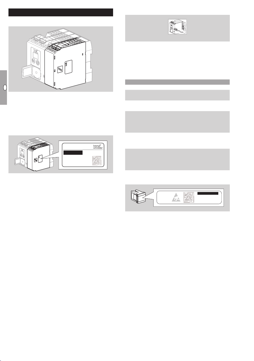
Checking the usage
Power module
Suitable for control units BCU500 or FCU500. With
relay contacts for the fail-safe outputs, e.g. for fan,
butterfly valve and valves. To replace a power module with the same identification number if fault 36
is displayed.
Identification number– see type label.
FCU 500
Parameter chip card
The parameter chip card is required for operation of
control units BCU500 or FCU500. All the parameters
specific to the system are saved on the parameter
chip card. To replace a parameter chip card with
identical type code, see type label.
Type code
Code Description
500 Parameter chip card for BCU/FCU500
Q
W
C0
C1
F0
F1
F2
H0
H1
K0
K1
K2
Mains voltage: 120 V AC, 50/60 Hz
230 V AC, 50/60 Hz
No tightness control or POC
With tightness control or POC
Capacity control:
none
with interface for actuator IC
with interface for RBW
Temperature monitoring:
none
with temperature monitoring
Connection terminals:
none
screw terminals
spring force terminals
Type code– see type label.
GB-2
Page 3

GB
F
NL
I
E
Replacing the power module and parameter chip card
Switch off the system.
2
Detach the FCU or BCU from the DIN rail in
order to facilitate replacing the power module
or parameter chip card.
4 5
▷
If an incorrect or defective power module is used,
the display of the control unit shows the blinking
message
on commissioning.
36
7 Slide on the (new) power module.
8 Place the control unit onto the DIN rail.
9 Reconnect the connection terminals.
▷ Ensure correct terminal assignment.
WARNING
Risk of explosion! Do not enable the control unit for
operation until the parameter settings and wiring
are correct and the faultless processing of all input
and output signals has been ensured.
0 Commission the control unit as described in the
operating instructions for the control unit.
6 Having removed the power module, replace the
parameter chip card if required.
▷
The type codes (see type label) of the old and
new parameter chip card must be identical.
▷ If an incorrect or defective parameter chip card
is used, the display of the control unit shows the
blinking message on commissioning.
▷
The identification numbers of the old and new
power module must be identical.
GB-3
Page 4

GB
F
NL
I
E
Assistance in the event of malfunction
▷
Further fault messages can be found in
the operating instructions of the relevant
control unit.
DANGER
Electric shocks can be fatal! Before working on
possible live components, ensure the unit is disconnected from the power supply.
Fault-clearance must only be undertaken by authorized, trained personnel.
▷ Faults may be cleared only using the measures
described below.
▷
If the control unit does not respond even though
all faults have been remedied: remove the unit
and return it to the manufacturer for inspection.
? Faults
! Cause
• Remedy
? The 7-segment display does not light up.
! Mains voltage is not applied.
• Check the wiring, apply mains voltage (see type
label).
3 6
? The display blinks and indicates
! Incorrect power module, faulty parameterization.
• Check parameter settings using BCSoft.
! The unit has suffered an internal fault.
! No power module.
! Relay contact does not open.
• Remove the unit and return it to the manufacturer
for inspection.
? The display blinks and indicates
! Parameter chip card (PCC) not correct, defective
or missing.
• Only the intended parameter chip card is to be
used.
• Replace defective parameter chip card.
36
.
.
Technical data
Connection terminals:
Screw terminals:
nominal cross-section 2.5mm²,
wire cross-section (rigid) min. 0.2mm²,
wire cross-section (rigid) max. 2.5mm²,
wire cross-section AWG/kcmil min. 24,
wire cross-section AWG/kcmil max. 12,
12 A.
Spring force terminals:
nominal cross-section 2 x 1.5mm²,
wire cross-section min. 0.2mm²,
wire cross-section AWG min. 24,
wire cross-section AWG max. 16,
wire cross-section max. 1.5mm²,
rated current 10 A (8A UL),
to be observed in case of daisy chain.
Contact rating:
control outputs LDS (terminal16), purge (terminal17), HT (terminal18), safety interlocks (terminal57): max. 0.5 A, cos ϕ = 1,
gas valves V1 (terminal13), V2 (terminal14), V3
(terminal15): max. 1 A, cos ϕ = 1,
air valve (terminals 53, 54 and55): max. 50 mA,
cos ϕ = 1.
The total current for the simultaneous activation of
outputs V1, V2, V3, HT, purge, LDS, safety interlocks and air valve must not exceed 2.5A.
24 V DC signal for fault/operation: max. 0.1 A,
fan: max. 3 A (start-up current: 6A<1s).
Number of operating cycles of power module:
control outputs LDS (terminal16), purge (terminal17), HT (terminal18), safety interlocks
(terminal57),
gas valves V1 (terminal 13), V2 (terminal14), V3
(terminal15),
air valve (terminals 53, 54 and55),
fan (terminal 58):
max. 250,000.
Contact
Contact
If you have any technical questions, please contact
your local branch office/agent. The addresses are
available on the Internet or from ElsterGmbH.
We reserve the right to make technical modifications
in the interests of progress.
Strotheweg 1, D-49504 Lotte (Büren)
Elster GmbH
Tel. +49 541 1214-0
Fax +49 541 1214-370
hts.lotte@honeywell.com, www.kromschroeder.com
GB-4
 Loading...