

Page 1
D
D
GB
D
GB
F
D
GB
F
NL
D
GB
F
NL
I
D
GB
F
NL
I
E
TR CZ PL RUS H
DK S N P GR
➔
www.docuthek.com
6.1.3.2 Edition 10.11
Brennersteuerung
BCU 370
03250470 10.11 Fx/ivd
Betriebsanleitung
Bitte lesen und aufbewahren
Zeichenerklärung
,
, , ... = Tätigkeit
= Hinweis
Alle in dieser Betriebsanleitung
aufgeführten Tätigkeiten dürfen
nur von autorisiertem Fach personal ausgeführt werden!
WARNUNG! Unsachgemäßer
Ein bau, Einstellung, Verän de rung,
Be die nung oder War tung kann
Ver letzungen oder Sachschäden
verursachen.
Anleitung vor dem Gebrauch lesen.
Dieses Gerät muss nach den geltenden Vorschriften installiert werden.
Inhaltsverzeichnis
Konformitäts erklärung 2
Prüfen 3
Einbauen 4
Leitungen auswählen 4
Verdrahten 6
BCU 370 mit Stellantrieb
IC 20/IC 20..E 10
Einstellen 11
In Betrieb nehmen 12
Sicherheitsfunktionen prüfen 16
Handbetrieb 17
Hilfe bei Störungen 19
Flammensignal/
Parameter ablesen 27
Zubehör 29
Legende 30
Technische Daten 31
Burner control unit
BCU 370
Operating instructions
Please read and keep in a safe
place
Explanation of symbols
,
, , ... = Action
= Instruction
All the work set out in these
operating instructions may only
be completed by authorized
trained personnel!
WARNING! Incorrect installation,
adjustment, modification, operation
or maintenance may cause injury or
material damage.
Read the instructions before use.
This unit must be installed in accord-
ance with the regulations in force.
Contents
Declaration of conformity 2
Testing 3
Installation 4
Cable selection 4
Wiring 6
BCU 370 with actuator
IC 20/IC 20..E 10
Adjustment 11
Commissioning 12
Checking the safety functions 16
Manual mode 17
Assistance in the event
of malfunction 19
Reading off the flame signal
and the parameters 27
Accessories 29
Legend 30
Technical data 31
Commande de brûleur
BCU 370
Instructions de service
À lire attentivement et à
conserver
Légendes
,
, , ... = action
= remarque
Toutes les actions mentionnées
dans les présentes instructions de
service doivent être exécutées par
des spécialistes formés et autorisés uniquement !
ATTENTION ! Un montage, un ré-
glage, une modi fication, une utilisation ou un entretien in adaptés risquent d’engendrer des dom mages
matériels ou corporels.
Lire les instructions avant utilisation.
Cet appareil doit être installé en respectant les règlements en vigueur.
Sommaire
Déclaration de conformité 2
Vérifier 3
Montage 4
Choix des câbles 4
Câblage 6
BCU 370 avec servomoteur
IC20 / IC 20..E 10
Réglages 11
Mise en service 12
Vérifier les fonctions de
sécurité 16
Mode manuel 17
Aide en cas de défauts 19
Lire le signal de flamme
et les paramètres 27
Accessoires 29
Légende 30
Caractéristiques
techniques 31
Branderbesturing
BCU 370
Bedieningsvoorschrift
Lezen en goed bewaren a.u.b.
Legenda
,
, , ... = werkzaamheden
= aanwijzing
Alle in deze bedrijfshandleiding
vermelde werkzaamheden mogen alleen door technici worden
uitgevoerd!
WAARSCHUWING! Ondeskundi-
ge inbouw, instelling, wijziging,
bediening of onder houds werk zaamheden kunnen per soonlijk letsel of
materiële schade veroor zaken.
Aanwijzingen voor het gebruik lezen.
Dit apparaat moet overeenkomstig de geldende regels worden
geïnstalleerd.
Inhoudsopgave
Verklaring van
overeenstemming 2
Controleren 3
Inbouwen 4
Bedrading kiezen 4
Bedraden 6
BCU 370 met stelaandrijving
IC20/IC 20..E 10
Instellen 11
In bedrijf stellen 12
Veiligheidsfuncties
controleren 16
Handbedrijf 17
Hulp bij storingen 19
Aflezen van het vlamsignaal
en de parameters 27
Toebehoren 29
Legende 30
Technische gegevens 31
Unità di controllo
bruciatore BCU 370
Istruzioni d’uso
Si prega di leggere e conser-
vare
Spiegazione dei simboli
,
, , ... = Operazione
= Avvertenza
Tutte le operazioni indicate nelle
presenti istruzioni d’uso devono
essere eseguite soltanto dal preposto esperto autorizzato.
ATTENZIONE! Se montaggio,
re go lazione, modifica, utilizzo o
manu tenzione non vengono ese guiti
correttamente, possono veri ficarsi
infortuni o danni.
Si prega di leggere le istruzioni prima
di utilizzare il prodotto che dovrà venire installato in base alle normative
vigenti.
Indice
Dichiarazione di conformità 2
Verifica 3
Montaggio 4
Scelta dei conduttori 4
Cablaggio 6
BCU 370 con servomotore
IC20/IC 20..E 10
Regolazione 11
Messa in servizio 12
Controllo delle
funzioni di sicurezza 16
Funzionamento manuale 17
Interventi in caso di guasti 19
Lettura segnale di fiamma/
parametri 27
Accessori 29
Legenda 30
Dati tecnici 31
Control de quemador
BCU 370
Instrucciones de
utilización
Se ruega que las lean y conser-
ven
Explicación de símbolos
,
, , ... = Actividad
= Indicación
¡Todas las actividades indicadas
en estas Instrucciones de utilización, sólo deben realizarse por
una persona formada y autorizada!
¡ADVERTENCIA! La instalación,
ajuste, modificación, manejo o mantenimiento incorrecto puede ocasionar daños personales o mate riales.
Leer las instrucciones antes de usar.
Este dispositivo debe ser instalado
observando las normativas en
vigor.
Índice
Declaración de conformidad 2
Comprobar 3
Montaje 4
Selección de los cables 4
Cableado 6
BCU 370 con servomotor
IC20 / IC 20..E 10
Ajuste 11
Puesta en funcionamiento 12
Comprobar las funciones
de seguridad 16
Funcionamiento manual 17
Ayuda en caso de averías 19
Lectura de la señal de
llama y de los parámetros 27
Accesorios 29
Leyenda 30
Datos técnicos 31
- 1 -
Page 2

Konformitäts erklärung
Wir erklären als Hersteller, dass
das Produk t BCU 370
kennzeichnet mit der Produkt-ID-Nr
CE-0063BP1283, die grundlegenden
An for derungen folgender Richtlinien
erfüllt:
– 90/396/EEC in Verbindung mit
EN298,
– 2006/95/EC in Verbindung mit
EN60730,
– 2004/108/EC in Verbindung mit
den einschlägigen Normen hin-
sichtlich der Einstrahlung.
PROFIBUS-DP-Schnittstelle entspricht den Anforderungen der
EN50170-2.
Das entsprechend bezeichnete Produkt stimmt überein mit dem bei der
zugelassenen Stelle 0063 geprüften
Baumuster.
Eine umfassende Qualitätssicherung
ist gewährleistet durch ein zertifiziertes Qualitätsmanagementsystem
nach DIN EN ISO 9001, gemäß
Anhang II, Absatz 3 der Richtlinie
90/396/EWG.
Elster GmbH
Klassifizierung nach EN 298
BCU 370:
B, B oder M, L oder C, L, J, B.
Bei UV-Überwachung in Verbin-
dung mit Elster Kromschröder
UV-Sonden UVS 1, UVS 5, UVS
6 oder UVS 10 einsetzbar nach
Gasgeräte- und Maschinenricht-
linie. In Verbindung mit der UV-
Sonde UVD 1 einsetzbar nach
Maschinenrichtlinie.
CSA zugelassen
Canadian Standards Association
Klasse: 3335-01 und 3335-81 Automatische (Gas-)Zündanlagen und
Bauteile.
Bei UV-Überwachung in Verbin-
dung mit Elster Kromschröder
UV-Sonde UVS 6, UVS 8 oder
UVS 10.
FM zugelassen
Factory Mutual Research Klasse:
7610 Verbrennungsabsicherung und
Flammenwächteranlagen. Passend
für Anwendungen gemäß NFPA 86.
Bei UV-Überwachung in Verbin-
dung mit Elster Kromschröder
UV-Sonde UVS 6, UVS 8 oder
UVS 10.
AGA-Zulassung
Australian Gas Association, Zulassungs-Nr.: 6880
Bei UV-Überwachung in Verbindung
mit Elster Kromschröder UV-Sonde
UVS 1, UVS 5, UVS 6 oder UVS 10.
UL zugelassen (BCU 370Q ohne
internen Zündtrafo)
Underwriters Laboratories – UL 372
„Primary Safety Controls for Gas- and
Oil-Fired Appliances“
Bei UV-Überwachung in Verbin-
dung mit Elster Kromschröder UV-
Sonde UVS 8 oder UVS 10 (außer
UVS 10..P2 und UVS 10D5).
, g e-
Declaration of conformity
.
AGA
We, the manufacturer, hereby declare
that the product BCU 370, marked
with product ID No. CE-0063BP1283,
complies with the essential requirements of the following Directives:
– 90/396/EEC in conjunction with
EN 298,
– 2006/95/EC in conjunction with
EN60730,
– 2004/108/EC in conjunction with
the relevant standards relating to
radiation.
The PROFIBUS DP interface complies
with the requirements of EN 50170-2.
The relevant product corresponds to
the type tested by the notified body
0063.
Comprehensive quality assurance
is guaranteed by a certified Quality
System pursuant to DIN EN ISO 9001
according to annex II, paragraph 3 of
Directive 90/396/EEC.
Elster GmbH
Classification pursuant to EN 298
BCU 370:
B, B or M, L or C, L, J, B.
In the case of UV control in con-
junction with Elster Kromschröder
UV sensors UVS 1, UVS 5, UVS
6 or UVS 10, may be used pursu-
ant to the Gas Appliances and Ma-
chinery Directives. In conjunction
with UV sensor UVD 1, may be
used pursuant to the Machinery
Directive.
CSA approved
Canadian Standards Association
Class: 3335-01 and 3335-81 “Systems (Gas)-Automatic Ignition and
Components”.
In the case of UV control in conjunc-
tion with Elster Kromschröder UV
sensor UVS 6, UVS 8 or UVS10.
FM approved
Factory Mutual Research Class: 7610
“Combustion Safeguards and Flame
Sensing Systems”. Suitable for applications pursuant to NFPA 86.
In the case of UV control in conjunc-
tion with Elster Kromschröder UV
sensor UVS 6, UVS 8 or UVS 10.
AGA approval
Australian Gas Association, Approval
No.: 6880
In the case of UV control in con-
junction with Elster Kromschröder
UV sensor UVS 1, UVS 5, UVS 6
or UVS 10.
UL listed (BCU 370Q without internal ignition transformer)
Underwriters Laboratories – UL 372
“Primary Safety Controls for Gas- and
Oil-Fired Appliances”
In the case of UV control in con-
junction with Elster Kromschröder
UV sensor UVS 8 or UVS 10 (ex-
cept UVS 10..P2 and UVS 10D5).
Déclaration de conformité
En tant que fabricant, nous déclarons
que le produit BCU 370, identifié par le
numéro de produit CE-0063BP1283,
répond aux exigences essentielles
des directives suivantes :
– 90/396/CEE en association avec
la EN 298,
– 2006/95/CE en association avec
EN60730,
– 2004/108/CE en association avec
les normes relatives au rayonne-
ment.
L’interface PROFIBUS DP respecte les exigences de la norme
EN 50170-2.
Le produit désigné en conséquence
est conforme au type éprouvé auprès
de l’organisme notifié 0063.
Une assurance de la qualité est garantie par un système qualité certifié
selon DIN EN ISO 9001, conformément à l’annexe II, paragraphe 3 de
la directive 90/396/CEE.
Elster GmbH
Classification conforme à EN 298
BCU 370 :
B, B ou M, L ou C, L, J, B.
Utilisable lors du contrôle UV en
combinaison avec les cellules UV
UVS 1, UVS 5, UVS 6 ou UVS 10
de Elster Kromschröder selon les
directives « appareils à gaz » et
«machines ». Utilisable en com-
binaison avec la cellule UV UVD 1
selon la directive « machines ».
Homologation CSA
Classe Canadian Standards Association : 3335-01 et 3335-81 Systèmes
d’allumage (gaz) automatiques et
composants.
Lors du contrôle UV en combinaison
avec les cellules UV UVS 6, UVS 8
ou UVS 10 de Elster Kromschröder.
Homologation FM
Classe Factory Mutual Research :
7610 Protection de combustion et
systèmes de détection de flamme.
Convient pour des applications
conformes à NFPA 86.
Lors du contrôle UV en combinaison
avec les cellules UV UVS 6, UVS 8
ou UVS 10 de Elster Kromschröder.
Homologation AGA
Australian Gas Association, n° d’homologation : 6880
Lors du contrôle UV en combinai-
son avec les cellules UV UVS 1,
UVS 5, UVS 6 ou UVS 10 de Elster
Kromschröder.
Homologation UL (BCU 370Q sans
transformateur d’allumage interne)
Underwriters Laboratories – UL 372
«Primary Safety Controls for Gas- and
Oil-Fired Appliances » (Dispositifs de sécurité primaires pour brûleurs gaz et fuel)
Lors du contrôle UV en combinai-
son avec les cellules UV UVS 8 ou
UVS 10 de Elster Kromschröder
(sauf UVS 10..P2 et UVS 10D5).
Verklaring van overeenstemming
Wij verklaren als fabrikant dat het
product BCU 370, gemerkt met het
product-identificatienummer CE0063BP1283, aan de fundamentele
voorschriften van de volgende richtlijnen voldoet:
– 90/396/EEG in combinatie met
EN 298,
– 2006/95/EG in combinatie met
EN60730,
– 2004/108/EG in combinatie met
de toepasbare normen met be-
trekking tot de instraling.
De PROFIBUS DP interface voldoet
aan de bepalingen van EN 50170-2.
Het overeenkomstig geïdentificeerd
product komt overeen met het door
de aangewezen instantie 0063 gecontroleerde type.
Een uitgebreide kwaliteitsborging
wordt gegarandeerd door een gecertificeerd kwaliteitsborgingsysteem
conform DIN EN ISO 9001 overeenkomstig bijlage II, lid 3 van de richtlijn
90/396/EEG.
Elster GmbH
Classificatie conform EN 298
BCU 370:
B, B of M, L of C, L, J, B.
Bij UV-bewaking in combinatie met
Elster Kromschröder UV-sondes
UVS 1, UVS 5, UVS 6 of UVS 10
toepasbaar volgens de richtlijnen
voor gastoestellen en machines.
In combinatie met de UV-sonde
UVD 1 toepasbaar volgens de
richtlijn voor machines.
CSA goedgekeurd
Canadian Standards Association
klasse: 3335-01 en 3335-81 Automatische (gas-)ontstekingsinstallaties
en bouwcomponenten.
Bij UV-bewaking in combinatie met
Elster Kromschröder UV-sonde
UVS 6, UVS 8 of UVS 10.
FM goedgekeurd
Factory Mutual Research klasse:
7610 Verbrandingsbeveiliging en
vlamrelaisinstallaties. Passend voor
toepassingen conform NFPA 86.
Bij UV-bewaking in combinatie met
Elster Kromschröder UV-sonde
UVS 6, UVS 8 of UVS 10.
AGA-goedkeuring
Australian Gas Association, goedkeuringsnr.: 6880
Bij UV-bewaking in combinatie met
Elster Kromschröder UV-sonde
UVS 1, UVS 5, UVS 6 of UVS 10.
UL goedgekeurd (BCU 370Q zonder interne ontstekingstransformator)
Underwriters Laboratories – UL 372
“Primary Safety Controls for Gas- and
Oil-Fired Appliances” (Primaire veiligheidsvoorzieningen voor gas- en
olietoestellen)
Bij UV-bewaking in combinatie met
Elster Kromschröder UV-sonde
UVS 8 of UVS 10 (behalve UVS
10..P2 en UVS 10D5).
- 2 -
Dichiarazione di conformità
Dichiariamo in qualità di produttori
che il prodotto BCU 370, contrassegnato con il numero d’identificazione del prodotto CE-0063BP1283,
risponde ai requisiti essenziali posti
dalle direttive seguenti:
– 90/396/CEE unitamente a EN 298,
– 2006/95/CE unitamente a
EN60730,
– 2004/108/CE unitamente a le
norme pertinenti relative alle per-
turbazioni elettromagnetiche.
L’interfaccia PROFIBUS DP soddisfa
i requisiti della EN 50170-2.
Il prodotto con tale contrassegno corrisponde al tipo esaminato dall’organismo notificato 0063.
La totale sicurezza della qualità è garantita da un sistema certificato di gestione della qualità ai sensi della DIN
EN ISO 9001, in base all’allegato II,
comma 3 della direttiva 90/396/CEE.
Elster GmbH
Classificazione secondo EN 298
BCU 370:
B, B o M, L o C, L, J, B.
In caso di controllo UV utilizzabile
in combinazione con sonde UV
Elster Kromschröder UVS 1, UVS
5, UVS 6 o UVS 10 conformemen-
te alla direttiva sugli apparecchi a
gas e alla direttiva sulle macchine.
Utilizzabile in combinazione con la
sonda UVD 1 conformemente alla
direttiva sulle macchine.
Approvazione CSA
Classe Canadian Standards Association: 3335-01 e 3335-81 Impianti
automatici di accensione (a gas) e
componentistica.
In caso di controllo UV in combina-
zione con sonde UV Elster Krom-
schröder UVS 6, UVS 8 o UVS 10.
Approvazione FM
Classe Factory Mutual Research: 7610
Protezione in materia di combustione e
impianti con relè di fiamma. Applicabile
per utilizzi secondo NFPA 86.
In caso di controllo UV in combinazio-
ne con sonde UV Elster Kromschröder
UVS 6, UVS 8 o UVS 10.
Approvazione AGA
Australian Gas Association, approvazione nº: 6880
In caso di controllo UV in combina-
zione con sonde UV Elster Krom-
schröder UVS 1, UVS 5, UVS 6 o
UVS 10.
Approvazione UL (BCU 370Q senza
trasformatore di accensione interno)
Underwriters Laboratories – UL 372 “Primary Safety Controls for Gas- and OilFired Appliances” (Dispositivi di sicurezza
primari per bruciatori a gas e a nafta)
In caso di controllo UV in com-
binazione con sonde UV Elster
Kromschröder UVS 8 o UVS 10
(ad eccezione di UVS 10..P2 e
UVS10D5).
Declaración de conformidad
Nosotros, el fabricante, declaramos
que el producto BCU 370, identificado por el Nº ID de producto
CE-0063BP1283, cumple con los
requisitos básicos de las siguientes
Directivas:
– 90/396/CEE en relación con
EN 298,
– 2006/95/CE en relación con
EN60730,
– 2004/108/CE en relación con las
normas correspondientes respecto
a las emisiones electromagnéticas.
La interfaz PROFIBUS DP satisface los requisitos de la norma
EN50170-2.
El producto correspondientemente
marcado coincide con el modelo
constructivo ensayado en el Organismo Notificado 0063.
El exhaustivo control de calidad está
garantizado por un sistema de gestión
de calidad, certificado conforme a la norma DIN EN ISO 9001 según el Anexo II,
Párrafo 3 de la Directiva 90/396/CEE.
Elster GmbH
Clasificación según EN 298 BCU 370:
B, B o M, L o C, L, J, B.
En el control de llama mediante son-
da UV utilizable en combinación con
las sondas UV de Elster Kromschrö-
der UVS 1, UVS 5, UVS 6 o UVS
10 según las Directivas sobre los
aparatos de gas y de maquinaria.
En combinación con la sonda UV
UVD 1 utilizable de acuerdo con la
Directiva de maquinaria.
Aprobación CSA
Clase Canadian Standards Association: 3335-01 y 3335-81 Instalaciones automáticas de encendido (gas)
y componentes.
En el control de llama mediante
sonda UV en combinación con las
sondas UV de Elster Kromschrö-
der UVS 6, UVS 8 o UVS 10.
Aprobación FM
Clase Factory Mutual Research: 7610
Protección de la combustión e instalaciones de guardallamas. Apto para
aplicaciones según NFPA 86.
En el control de llama mediante
sonda UV en combinación con las
sondas UV de Elster Kromschrö-
der UVS 6, UVS 8 o UVS 10.
Aprobación AGA
Australian Gas Association, nº de
aprobación: 6880
En el control de llama mediante
sonda UV en combinación con las
sondas UV de Elster Kromschröder
UVS 1, UVS 5, UVS 6 o UVS 10.
Aprobación UL (BCU 370Q sin transformador de encendido interno)
Underwriters Laboratories – UL 372 “Primary Safety Controls for Gas- and Oil-Fired
Appliances” (Dispositivos de seguridad primarios para quemadores de gas y de fuel)
En el control de llama mediante
sonda UV en combinación con las
sondas UV de Elster Kromschröder
UVS 8 o UVS 10 (excepto
UVS 10..P2 y UVS 10D5).
Page 3
Prüfen
D-49018 Osnabrück, Germany
BCU 370
C US
BCU 370
Zum Steuern, Zünden und Überwachen von Gas-Gebläsebrennern im
intermittierenden Betrieb oder Dauerbetrieb. Die Zündung erfolgt direkt
oder mit einem Zündbrenner.
Mit UV-Sonden vom Typ UVS darf die
BCU nur für intermittierenden Betrieb
eingesetzt werden. Das heißt, der Betrieb muss innerhalb von 24 h einmal
unterbrochen werden.
Mit UV-Sonden vom Typ UVD 1 (Einsatz nur mit BCU 370..U1) darf die
BCU auch im Dauerbetrieb eingesetzt werden. Einzelheiten zum Anschluss – siehe Kapitel „Verdrahten“.
Die Zündung und Überwachung
mit einer Elektrode ist nur mit einem
geeigneten externen Zündtrafo, beispielsweise TGI, möglich.
BCU 370..B1, BCU 370..B1-3
mit PROFIBUS DP
Das Bussystem überträgt die Steuersignale zum Starten, Entriegeln und
Ventilieren von der Leitwarte (SPS) zur
BCU..B1. In Gegenrichtung übermittelt das Bussystem Betriebszustände,
die Höhe des Flammenstroms und
den aktuellen Programmstatus. Die
Sicherheitskette wird separat verdrahtet.
BCU 370..B1-3
Ansteuerung der Drosselklappe über
PROFIBUS DP.
BCU 370Q..B1 mit UL-Zulassung
Geräte nur in Applikationen einsetzen,
in denen eine Fernentriegelung des
Brenners zulässig ist.
Lieferumfang:
BCU 370,
2 Kabelverschraubungen M16,
Aufklebersatz D, F, I, NL, E,
Aufkleber „geänderte Parameter“,
2 Steckverbinder für Zündleitung.
Netzspannung, Schutzart und
Umgebungstemperatur (keine
Betauung auf den Leiterplatten
zulässig) – siehe Typenschild.
Einstellung der Geräteparameter
überprüfen – siehe beigelegten
Lieferschein.
Testing
BCU 370
For controlling, igniting and monitoring
forced draught gas burners in intermittent or continuous operation. The
burner is ignited directly or using a
pilot burner.
The BCU may be used only for intermittent operation with UV sensors of
Type UVS. This means that operation must be interrupted once within
24 hours.
With UV sensors of Type UVD 1 (only
suitable for use with BCU 370..U1) the
BCU may also be used for continuous
operation. Connection details – see
section entitled “Wiring”.
Ignition and monitoring with a single
electrode is only possible with an appropriate external ignition transformer,
for example TGI.
BCU 370..B1, BCU 370..B1-3
with PROFIBUS DP
The bus system transfers the control
signals for starting, resetting and for
controlled air flow from the control
system (PLC) to the BCU..B1. In the
opposite direction the bus system
sends operating status, the level of
the flame signal and the current program status. The safety interlocks are
wired separately.
BCU 370..B1-3
For controlling the butterfly valve via
PROFIBUS DP.
BCU 370Q..B1 with UL approval
Use units only in applications where
remote reset of the burner is permitted.
Scope of delivery:
BCU 370,
2 M16 cable glands,
set of stickers in D, F, I, NL, E,
“Changed parameters” sticker,
2 plug connectors for ignition ca-
ble.
Mains voltage, enclosure and am-
bient temperature (no condensation permitted on the PC boards) –
see type label.
Check adjustment of unit param-
eters – see enclosed delivery note.
Vérifier
BCU 370
Pour la commande, l’allumage et la
surveillance de brûleurs gaz à air soufflé en service intermittent ou continu.
L’allumage se produit directement ou
à l’aide d’un brûleur d’allumage.
Lorsqu’il est équipé de cellules UV
de type UVS, le BCU doit être utilisé
en service intermittent uniquement.
Cela signifie qu’en 24 heures, le
fonctionnement doit être interrompu
une fois.
Lorsqu’il est équipé de cellules UV de
type UVD 1 (utilisation uniquement
avec BCU 370..U1), le BCU peut également être utilisé en service continu.
Informations sur le raccordement –
voir le chapitre «Câblage».
L’allumage et le contrôle avec une
seule électrode n’est possible qu’avec
un transformateur d’allumage externe
approprié, TGI par exemple.
BCU 370..B1, BCU 370..B1-3
avec PROFIBUS DP
Le système de bus transmet les signaux de commande de démarrage,
de réarmement et de ventilation de
l’automate (API) au BCU..B1. Dans
le sens inverse, le système de bus
transmet les états de fonctionnement,
l’intensité du courant de flamme et
l’état actuel du programme. La chaîne
de sécurité est câblée séparément.
BCU 370..B1-3
Commande de la vanne papillon par
PROFIBUS DP.
BCU 370Q..B1 avec homologation UL
N’utiliser les appareils que dans des
applications pour lesquelles un réarmement à distance du brûleur est
admis.
Programme de livraison :
BCU 370,
2 presse-étoupes pour câble M16,
jeu d’étiquettes adhésives D, F, I,
NL, E,
étiquette adhésive «Paramètres
modifiés»,
2 connecteurs pour câble d’allu-
mage.
Tension secteur, type de protection
et température ambiante (condensation sur les plaquettes à circuit
imprimé non admise) – voir la
plaque signalétique.
Vérifier le réglage des paramètres
de l’appareil – voir le bon de livraison fourni.
Controleren
BCU 370
Voor het besturen, ontsteken en bewaken van gas-ventilatorbranders in
intermitterend bedrijf of continubedrijf.
De ontsteking gebeurt rechtstreeks of
met een aansteekbrander.
Met UV-sondes van het type UVS
mag de BCU alleen in intermitterend
bedrijf worden toegepast. Dat wil zeggen dat de werking binnen 24 uur één
keer moet worden onderbroken.
Met UV-sondes van het type UVD 1
(toepassing alleen met BCU 370..U1)
mag de BCU ook in continubedrijf
worden toegepast. Details voor
het aansluiten – zie het hoofdstuk
“Bedraden”.
De ontsteking en bewaking met een
elektrode is alleen met een geschikte
externe ontstekingstransformator, bijvoorbeeld TGI, mogelijk.
BCU 370..B1, BCU 370..B1-3
met PROFIBUS DP
Het bussysteem zendt de stuursignalen voor het starten, ontgrendelen
en ventileren van het controlesysteem
(PLC) naar de BCU..B1. In tegenovergestelde richting zendt het bussysteem gegevens over bedrijfstoestanden, de hoogte van de vlamstroom
en de actuele programmastatus.
Het voorwaardencircuit wordt apart
bedraad.
BCU 370..B1-3
Aansturing van de gasklep via
PROFIBUS DP.
BCU 370Q..B1 met UL-goedkeuring
Apparaten alleen in applicaties gebruiken, waarin het ontgrendelen op
afstand van de brander toegestaan is.
Leveringsomvang
BCU 370,
2 kabelwartels M16,
stickerset D, F, I, NL, E,
sticker “Gewijzigde parameters”,
2 connectors voor ontstekingska-
bel.
Netspanning, beschermingswijze
en omgevingstemperatuur (geen
condensatie op de printkaarten
toegestaan) – zie typeplaatje.
Instelling van de hardwareparame-
ters controleren – zie bijgevoegd
afleveringsbewijs.
Verifica
BCU 370
Per il comando, l’accensione e il controllo di bruciatori a gas con soffiante
a funzionamento intermittente o continuo. L’accensione si effettua direttamente o con un bruciatore pilota.
Con le sonde UV tipo UVS, la BCU
può essere usata solo per funzionamento intermittente. Ciò significa che
il funzionamento deve essere interrotto almeno una volta ogni 24 ore.
Con le sonde UV tipo UVD 1 (utilizzo
solo con BCU 370..U1), la BCU può
essere usata anche in funzionamento
continuo. Per informazioni dettagliate sul collegamento vedere capitolo
“Cablaggio”.
L’accensione e il controllo mediante
un elettrodo sono possibili solo con un
apposito trasformatore di accensione
esterno, ad es. TGI.
BCU 370..B1, BCU 370..B1-3
con PROFIBUS DP
Il sistema bus trasmette i segnali di
comando per l’avvio, il ripristino e
la ventilazione dal quadro comandi
(PLC) alla BCU..B1. Il sistema bus
invia in senso contrario le condizioni
di funzionamento, l’intensità del segnale fiamma e lo stato di programma
in corso. La catena dei dispositivi di
sicurezza è cablata separatamente.
BCU 370..B1-3
Attivazione della valvola a farfalla tramite PROFIBUS DP.
BCU 370Q..B1 con approvazione
UL
Usare gli apparecchi solo in applicazioni, in cui è consentito il ripristino a
distanza del bruciatore.
Corredo di fornitura per
BCU 370,
2 collegamenti a vite per cavo
M16,
etichette adesive D, F, I, NL, E,
etichetta adesiva “Parametri mo-
dificati”,
2 connettori a spina per il condut-
tore di accensione.
Tensione di rete, tipo di protezio-
ne e temperatura ambiente (non
è ammessa la formazione di con-
densa sui circuiti stampati) – vedi
targhetta dati.
Verificare l’impostazione dei para-
metri dell’apparecchio – vedi bolla
di accompagnamento allegata.
Comprobar
BCU 370
Para controlar, encender y vigilar
quemadores de gas con ventilador
en funcionamiento intermitente o
continuo. El encendido se realiza directamente o con un quemador de
encendido.
Con sondas UV del tipo UVS sólo debe emplearse el BCU para operación
intermitente. Es decir, la operación
debe interrumpirse una vez cada
24 horas.
Con sondas UV del tipo UVD 1 (utilización sólo con BCU 370..U1) también
se puede emplear el BCU en operación continua. Para detalles sobre la
conexión, ver capítulo “Cableado”.
El encendido y control con un electrodo solamente es posible con un
transformador de encendido externo
adecuado, por ejemplo el TGI.
BCU 370..B1, BCU 370..B1-3
con PROFIBUS DP
El sistema de bus transmite las señales de control para el arranque, el
desbloqueo y la ventilación desde el
puesto de mando (PLC = sistema de
programa almacenado) al BCU..B1.
El sistema de bus transmite en sentido contrario los estados operativos,
la magnitud de la llama y el estado
actual del programa. La cadena de
seguridad se cablea por separado.
BCU 370..B1-3
Control de la válvula de mariposa a
través de PROFIBUS DP.
BCU 370Q..B1 con aprobación UL
Utilizar los dispositivos solo para
aplicaciones en las que esté autorizado un desbloqueo a distancia del
quemador.
Componentes del suministro:
BCU 370,
2 racores roscados para cables
M16,
juego de etiquetas adhesivas en
D, F, I, NL, E,
etiqueta adhesiva de “parámetros
modificados”,
2 conectores para el cable de en-
cendido.
Para tensión de la red, grado de
protección y temperatura ambiente (evitar la formación de agua de
condensación en las placas de
circuitos impresos) – ver placa de
características.
Comprobar el ajuste de los pa-
rámetros del dispositivo – ver el
albarán de entrega adjunto.
- 3 -
Page 4
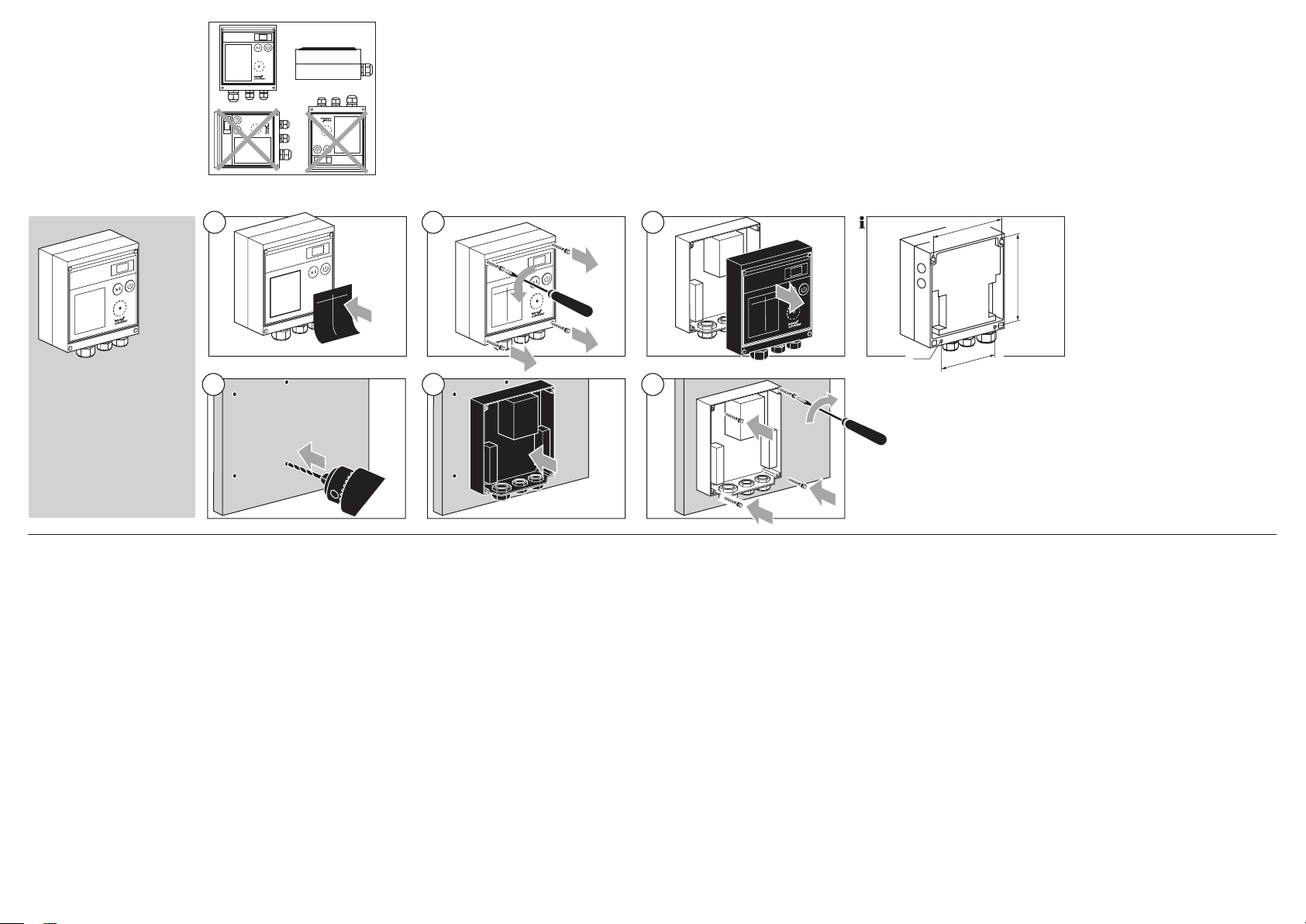
Einbauen
Empfohlene Einbaulage: senkrecht,
Kabelverschraubungen nach unten.
Aufkleber mit Statusbeschreibung
in der gewünschten Sprache
aufkleben – Aufklebersatz liegt der
BCU bei.
88
88
88
Installation
Recommended installation posi-
tion: vertical, cable glands pointing
downwards.
Affix the sticker with the status description in the required language –
a set of stickers is supplied with
the BCU.
Montage
Position de montage recomman-
dée : verticale, presse-étoupes
vers le bas.
Appliquer l’étiquette adhésive avec
description de l’état dans la langue
souhaitée – le jeu d’étiquettes adhésives est fourni avec le BCU.
Inbouwen
Aanbevolen inbouwpositie: verti-
caal, kabelwartels naar beneden.
Sticker met statusbeschrijving in
de gewenste taal aanbrengen –
stickerset wordt met de BCU
meegeleverd.
Montaggio
Posizione di montaggio consiglia-
ta: verticale, collegamenti a vite per
cavo rivolti verso il basso.
Attacare l’etichetta adesiva con
la descrizione di stato nella lingua
desiderata – etichette adesive ac-
cluse alla BCU.
Montaje
Posición de montaje recomenda-
da: vertical, con los racores roscados para cables hacia abajo.
Pegar la etiqueta adhesiva con la
descripción de estado en el idioma
deseado sobre el BCU – se adjunta al BCU un juego de etiquetas
adhesivas.
BCU 370
Leitungen auswählen
Betriebsbedingte Leitungen gemäß
den örtlichen Vorschriften verwenden.
Signal- und Steuerleitung:
max. 1,5 mm
Leitung für Anschluss UVD:
max. 1 mm
Leitung für Brennermasse:
4 mm
Leitungen der BCU nicht im sel-
ben Kabelkanal mit Leitungen von
Frequenzumrichtern und anderen
stark abstrahlenden Leitungen führen.
Elektrische Fremdeinwirkung ver-
meiden.
Für die Ionisations- und Zündlei-
tung Hochspannungskabel verwenden, nicht abgeschirmt:
FZLSi 1/7 bis 180 °C,
Best.-Nr. 04250410, oder
FZLK 1/7 bis 80 °C,
Best.-Nr. 04250409.
2
.
2
.
2
.
2
vfdsfsdvfd gfhfg
vfdsgfdbgfb gfhff
vfdfgdfxbhgdbgfb gfhfgf
vfdsgfdbgfb gfhfghgf
vfdbgfb gfhfghgf
vfdsgfdbgfb gfhfghgf
vfdghlkjsgfdbgfb gfhfghgf
vfdsgfngfdbgfb gfhgf
vfdsgfdbgfb gfhfg
vfdsfdbgfb gfhfg
gfhfghgf
gfhgf
gfhfg
gfhfg
5
3 4
gfhfg
vfdsfsdvfd
gf
vfdsgfdbgfb gfhff
fb gfhf
gfhfghgf
b
vfdfgdfxbhgdbg
gfdbgf
gfhfghgf
vfds
vfdbgfb
gfhfghgf
gfdbgfb
gfhfghgf
vfds
fb gfhgf
vfdghlkjsgfdbgfb
fb gfhfg
vfdsgfngfdbg
g
vfdsgfdb
b gfhfg
vfdsfdbgf
gfhfghgf
gfhf
gfh
6
Cable selection
Use cables suitable for the type of
operation and complying with local
regulations.
Signal and control line:
max. 1.5 mm
Cable for UVD connection:
max. 1 mm
Cable for burner ground:
4 mm
Do not route BCU cables in the
same cable duct as frequency
converter cables or cables emit-
ting strong fields.
Avoid external electrical influen ces.
For the ionization and ignition ca-
bles, use unscreened high-voltage
cable:
FZLSi 1/7 up to 180°C,
Order No. 04250410, or
FZLK 1/7 up to 80°C,
Order No. 04250409.
2
.
2
.
2
.
7
Choix des câbles
Utiliser des câbles appropriés –
conformes aux prescriptions locales.
Câble de signal et de commande :
1,5 mm2 maxi.
Câble pour raccordement UVD :
2
1 mm
maxi.
Câble de masse de brûleur :
4 mm2.
Ne pas poser les câbles du BCU
et les câbles des convertisseurs de
fréquence ou à fort rayonnement
électromagnétique dans le même
conduit.
Éviter les influences électriques
externes.
Pour les câbles d’ionisation et d’al-
lumage, utiliser des câbles haute
tension non blindés :
FZLSi 1/7 jusqu’à 180 °C,
N° réf. 04250410, ou
FZLK 1/7 jusqu’à 80 °C,
N° réf. 04250409.
gfhfg
vfdsfsdvfd
fb gfhff
gf
vfdsgfdbg
b gfhf
f
gfhfghgf
gf
vfdfgdfxbhgdbg
gfdbgfb
vfds
vfdbgfb gfhfgh
gfhfghgf
gfdbgfb
gfhfghgf
vfds
fb gfhgf
vfdghlkjsgfdbgfb
ngfdbg
vfdsgf
gfb gfhfg
vfdsgfdb
b gfhfg
sfdbgf
vfd
gfhfghgf
gfhf
gfh
Bedrading kiezen
Toepassingsafhankelijke bedrading
overeenkomstig de toepasselijke
voorschriften gebruiken.
Signaal- en stuurleiding:
max. 1,5 mm
Leiding voor UVD-aansluiting:
max. 1 mm
Leiding voor massa van de brander:
4 mm
De bedrading van de BCU niet
met samen met bedrading van
frequentieomzetters en andere
sterk stralende bedrading in de-
zelfde kabelgoot leggen.
Elektrische invloeden van buitenaf
voorkomen.
Voor de ionisatie- en ontstekings-
kabel niet-afgeschermde hoog-
spanningskabel gebruiken:
FZLSi 1/7 tot 180°C,
Bestelnr. 04250410, of
FZLK 1/7 tot 80°C,
Bestelnr. 04250409.
2
.
2
.
2
.
154
185
ø 5
138
Scelta dei conduttori
Utilizzare conduttori adeguati in
ottemperanza alle norme locali.
Conduttore di segnali e di comandi:
max. 1,5 mm
Conduttore per collegamento
UVD:
max. 1 mm
Conduttore per massa del bru-
ciatore:
4 mm
Non posare i conduttori della BCU
nella stessa canalina per cavi con
conduttori di convertitori di fre-
quenza e altri cavi di forte irradia-
zione.
Evitare interferenze elettriche ester-
ne.
Per i conduttori di ionizzazione e di
accensione utilizzare cavi ad alta
tensione non schermati:
FZLSi 1/7 fino a 180 °C,
n° d’ordine 04250410, oppure
FZLK 1/7 fino a 80 °C,
n° d’ordine 04250409.
2
.
2
.
2
.
Selección de los cables
Emplear cables adecuados a la
operación, de acuerdo con las
normas locales.
Cable de señales y control:
máx. 1,5 mm
Cable de conexión de la sonda
UVD:
máx. 1 mm
Cable para masa del quemador:
4 mm2.
No conducir los cables del BCU
por el mismo canal de cables por
el que discurren los conductores
de convertidores de frecuencia,
ni otros conductores que emitan
radiaciones intensas.
Evitar influencias eléctricas extrañas.
Utilizar cables de alta tensión no
blindados para los cables de ioni-
zación y de encendido:
FZLSi 1/7 hasta 180 °C,
Nº de referencia 04250410, ó
FZLK 1/7 hasta 80 °C,
Nº de referencia 04250409.
2
.
2
.
- 4 -
Page 5
A = Ionisationsleitung
BCU 370..I1..U0
1917 18 20 21 22 23 24 25 26 27 28 29 30 31 32
PE
BCU 370..I1..U0
1917 18 20 21 22 23 24 25 26 27 28 29 30 31 32
PE
PE
N (L2)
L1 (L1)
N
BCU 370..I1..U0
F1: T 5A H
IEC 60127-2/5
PE
V1
V2
V3
M
3PS
19 17 18 20 21 22 23 24 25 26 27 28 29 30 31 32
3 1 2 4 5 6 7 8 9 10 11 12 13 14 15 16
230 V
BCU 370..D3
0➞90°
90°➞0
1
2
3
UVS
= Limits
= Start
= Alarm
= Reset
ϑ
L1, L2 = Live
N = Neutral
PE = Ground
p
Gas
min.
p
Gas
max.
13 14 15
p
Air
p
e
/2
11 p 12
I
Z
N
BCU 370..I1..U0
PE
19 17 18 20 21 22 23 24 25 26 27 28 29 30 31 32
14 15 16
Z
BCU 370..I1..U0
19 17 18 20 21 22 23 24 25 26 27 28 29 30 31 32
BCU 370..I2
1917 18 20 21 22 23 24 25 26 27 28 29 30 31 32
BCU 370..I3
1917 18 20 21 22 23 24 25 26 27 28 29 30 31 32
B = UV-Leitung
Leitungslänge: max. 50 m.
Leitungen einzeln und möglichst
nicht im Metallrohr verlegen.
Zündleitung nicht parallel und
mit möglichst großem Abstand
zur UV-Leitung/Ionisationsleitung
verlegen.
Zündleitung bei integrierter,
elektronischer Zündeinheit
C = BCU..I1, einpolige Zündung
oder
D = BCU..I2, zweipolige Zündung
oder
E = BCU..I3, zweipolige Zündung
mit Mittelabgriff
Leitungslänge: max. 1 m.
Zündleitung(en) mittels Steckver-
binder (Zubehörsatz liegt dem
Gerät bei) fest mit der integrierten
Zündeinheit verbinden.
Leitung(en) einzeln und nicht im
Metallrohr verlegen.
Nur funkentstörte Elektrodenste-
cker verwenden.
Beispiel mit 1 kΩ Widerstand:
Winkelstecker 4 mm, funkentstört,
Best.-Nr. 04115308.
Gerader Stecker 4 mm, funkent-
stört, Best.-Nr. 04115307.
Gerader Stecker 6 mm, funkent-
stört, Best.-Nr. 04115306.
Zündleitung bei externer Zündung
F = Zündleitung bei Einelektrodenbetrieb
oder
G = Zündleitung bei
Zweielektro denbetrieb
Entsprechende Gerätehinweise
PROFIBUS-DP-Leitung bei
BCU 370..B1
Nur spezielles PROFIBUS-Kabel
Beispiel: Lappkabel Unitronic,
beachten, z. B. bei Zündtransfor-
mator TGI.
verwenden (Typ A, zweiadrig, ge-
schirmt mit Folien- und Geflechts-
schirm, verdrillt).
Best.-Nr. 2170220T Siemens,
6 x V 1 830-0EH10.
11 12 13
230 V
230 V
230 V
230 V
12 13 14 15 16
14 15 16
13 14 15 16
I
p
Gas
max.
A
N 16
B
PE
N
Z
I
PE
N
PE
N
13 14 15 16
13 14 15 16
C
Z
D
Z
Z
Z
N
Z
F
N
Z
I
A = Ionization cable
B = UV cable
Cable length: max. 50 m.
Lay cables individually and, if pos-
sible, not in a metal conduit.
Do not lay UV/ionization cable
and ignition cables together and
lay them as far apart as possible.
Ignition cable for units with integrated electronic ignition unit
C = BCU..I1, single-pole ignition
or
D = BCU..I2, double-pole ignition
or
E = BCU..I3, double-pole ignition
with centre tap
Cable length: max. 1 m.
Connect the ignition cable(s) se-
curely to the integrated ignition
unit using the plug connector(s)
(accessories kit supplied with the
unit).
Lay cable(s) individually and not in
a metal conduit.
Only use radio interference sup-
pressed electrode adapters.
Example with 1 kΩ resistor:
Plug cap, 4 mm, suppressed, Or-
der No. 04115308.
Straight adapter, 4 mm, sup-
pressed, Order No. 04115307.
Straight adapter, 6 mm, sup-
pressed, Order No. 04115306.
E
Ignition cable for units with external ignition
F = Ignition cable for single-electrode operation
or
G = Ignition cable for doubleelectrode operation
Please note the corresponding
unit instructions, e.g. for ignition
transformer TGI.
PROFIBUS DP cable for
BCU 370..B1
G
Only use special PROFIBUS cable
(Type A, two core, shielded with foil
and woven shield, twisted).
Example: Lapp cable Unitronic,
Order No. 2170220T Siemens,
6 x V 1 830-0EH10.
A = Câble d’ionisation
B = Câble UV
Longueur de câble : 50 m maxi.
Poser les câbles séparément et, si
possible, pas dans un tube métallique.
Ne pas tirer parallèlement les
câbles d’ionisation / UV et
d’allumage et prévoir un écartement maximal.
Câble d’allumage avec transformateur d’allumage électronique
intégré
C = BCU..I1, allumage unipolaire
ou
D = BCU..I2, allumage bipolaire
ou
E = BCU..I3, allumage bipolaire
avec point milieu
Longueur de câble : 1 m maxi.
Raccorder le(s) câble(s) d’allumage
au transformateur d’allumage intégré au moyen de connecteurs (le
set d’accessoires est fourni avec
l’appareil).
Poser le(s) câble(s) séparément et
non dans un tube métallique.
N’utiliser que des embouts d’élec-
trode antiparasités.
Exemple avec une résistance de
1 kΩ :
Embout coudé 4 mm, antiparasité,
N° réf. 04115308.
Embout droit 4 mm, antiparasité,
N° réf. 04115307.
Embout droit 6 mm, antiparasité,
N° réf. 04115306.
Câble d’allumage pour transformateur d’allumage externe
F = Câble d’allumage en contrôle
monoélectrode
ou
G = Câble d’allumage en contrôle
deux électrodes
Observer les instructions des ap-
pareils correspondantes, pour le
transformateur d’allumage TGI par
exemple.
Câble PROFIBUS DP pour
BCU 370..B1
Utiliser uniquement un câble PRO-
FIBUS spécial (type A, à deux
brins, blindé avec protection par
bande et tresse, torsadé).
Exemple : câble agrafé Unitronic,
N° réf. 2170220T Siemens,
6 x V 1 830-0EH10.
A = Ionisatiekabel
B = UV-kabel
Kabellengte: max. 50 m.
Bedrading afzonderlijk en bij voor-
keur niet in metalen buis installeren.
Ontstekingskabel en ionisatieka-
bel/UV-kabel niet parallel en met
zo groot mogelijke onderlinge afstand installeren.
Ontstekingskabel bij geïntegreerde, elektronische ontsteker
C = BCU..I1, eenpolige ontsteking
of
D = BCU..I2, dubbelpolige ontsteking
of
E = BCU..I3, dubbelpolige ontsteking met middelste aansluiting
Kabellengte: max. 1 m.
Ontstekingskabel(s) door middel
van de connector (set toebehoren met het apparaat meegeleverd) stevig op de geïntegreerde
ontsteker aansluiten.
Bedrading(en) gescheiden en niet
in metalen buis installeren.
Alleen ontstoorde elektrodenstek-
kers gebruiken.
Voorbeeld met 1 kΩ weerstand:
Haakse stekker 4 mm, radio-ont-
stoord, bestelnr. 04115308.
Rechte stekker 4 mm, radio-ont-
stoord, bestelnr. 04115307.
Rechte stekker 6 mm, radio-ont-
stoord, bestelnr. 04115306.
Ontstekingskabel bij externe ontsteking
F = Ontstekingskabel bij bedrijf
met één elektrode
of
G = Ontstekingskabel bij bedrijf
met twee elektroden
Bijbehorende aanwijzingen opvol-
gen, bijv. bij ontstekingstransfor-
mator TGI.
PROFIBUS DP leiding bij
BCU 370..B1
Alleen speciaal PROFIBUS-kabel
gebruiken (type A, tweeaderig,
afgeschermd met folie-ommante-
ling- en gevlochten afscherming,
getwist).
Voorbeeld: Lappkabel Unitronic,
Bestelnr. 2170220T Siemens,
6 x V 1 830-0EH10.
A = Conduttore di ionizzazione
B = Conduttore UV
Lunghezza conduttore: max. 50 m.
Posare i conduttori singolarmente
e, se possibile, non in tubo metallico.
Non posare in parallelo il condut-
tore di ionizzazione/UV e il conduttore di accensione e mantenere il
più possibile un’ampia distanza.
Conduttore di accensione con
unità di accensione elettronica
integrata
C = BCU..I1, accensione unipolare
oppure
D = BCU..I2, accensione bipolare
oppure
E = BCU..I3, accensione bipolare
con derivazione centrale
Lunghezza conduttore: max. 1 m.
Collegare il/i conduttore/i di ac-
censione con l’unità di accensione
integrata mediante il connettore a
spina (accessori forniti con l’apparecchio).
Posare il/i conduttore/i singolar-
mente e non in tubo metallico.
Utilizzare solo pipette dell’elettrodo
schermate.
Ad esempio con 1 kΩ di resisten-
za:
Pipetta angolare 4 mm, scherma-
ta, n° d’ordine 04115308.
Pipetta diritta 4 mm, schermata,
n° d’ordine 04115307.
Pipetta diritta 6 mm, schermata,
n° d’ordine 04115306.
Conduttore di accensione con
accensione esterna
F = Conduttore di accensione a
funzionamento monoelettrodo
oppure
G = Conduttore di accensione a
funzionamento bielettrodo
Attenersi alle indicazioni dell’appa-
recchio corrispondenti, ad es. per
il trasformatore di accensione TGI.
Conduttore PROFIBUS DP per
BCU 370..B1
Utilizzare solo il cavo speciale per
PROFIBUS (tipo A, a due fili, con
schermatura laminata e a rete,
ritorto).
Esempio: cavo Unitronic,
n° d’ordine 2170220T Siemens,
6 x V 1 830-0EH10.
A = Cable de ionización
B = Cable UV
Longitud del cable: máx. 50 m.
Instalar por separado los cables y,
a ser posible, nunca por el interior
de un tubo metálico.
Instalar el cable de encendido y el
cable de ionización/UV de forma
que no discurran paralelos y que
estén lo más distanciados posible.
Cable de encendido en caso de
unidad de encendido electrónico
integrada
C = BCU..I1, encendido monopolar
o
D = BCU..I2, encendido bipolar
o
E = BCU..I3, encendido bipolar
con toma central
Longitud del cable: máx. 1 m.
Conectar fijos el o los cables de
encendido mediante los conectores (juego de accesorios que se
adjunta al dispositivo) a la unidad
de encendido integrada.
Instalar por separado el o los ca-
bles y nunca por el interior de un
tubo metálico.
Emplear sólo clavijas desparasita-
das para electrodos.
Ejemplo con 1 kΩ de resistencia:
Clavija acodada Ø 4 mm, despara-
sitada, Nº de referencia 04115308.
Clavija recta Ø 4 mm, desparasi-
tada, Nº de referencia 04115307.
Clavija recta Ø 6 mm, desparasi-
tada, Nº de referencia 04115306.
Cable de encendido en caso de
encendido externo
F = Cable de encendido en caso
de operación con un electrodo
o
G = Cable de encendido en caso
de operación con dos electrodos
Tener en cuenta las correspon-
dientes indicaciones del equipo,
p. ej. en caso de transformador
de encendido TGI.
Cable PROFIBUS DP en
BCU 370..B1
Emplear sólo cable especial
PROFIBUS (Tipo A, bifilar, blinda-
do con pantalla de lámina y de
trenzado, retorcido).
Ejemplo: cable forrado Unitronic,
Nº de referencia 2170220T
Siemens,
6 x V 1 830-0EH10.
- 5 -
Page 6
Verdrahten
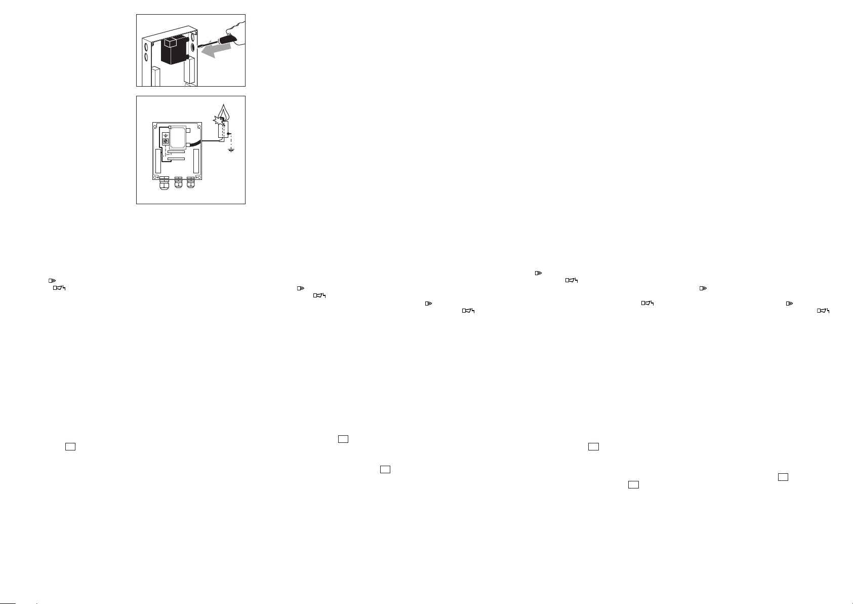
Zündleitung fest an die Zündeinheit
anschließen und auf kürzestem
Weg aus dem Gerät (keine Schlaufen) herausführen.
Die Zündeinheit kann um 180°
gedreht im Gehäuse montiert werden. BCU 370..B: Aus EMV-Grün-
den ist die Zündeinheit werksseitig
mit dem Hochspannungsausgang
nach links montiert. Richtung beibehalten.
Zur Verdrahtung der Zündleitung
sind Durchbrüche im Gehäuseunterteil vorbereitet.
Beigelegte M16-Verschraubung für
Zündleitung verwenden.
Für die Erdung des Brenners steht
eine Erdungsschiene im Gehäuseunterteil zur Verfügung.
Anschluss nur mit fester Verdrah-
tung.
Phase L1 und Neutralleiter N nicht
vertauschen.
An die Eingänge nicht verschie-
dene Phasen eines Drehstromnetzes legen.
An die Ausgänge keine Spannung
legen.
Ein Kurzschluss an den Ausgän-
gen zerstört die BCU.
Fernentriegelung nicht zyklisch
automatisch ansteuern.
Betriebsmeldekontakt (Klemmen
17, 18 ) und Störmeldekontakt
(19, 20 ): max. 1 A, 253 V,
nicht intern abgesichert.
Fühlerspannung oder Spannung
an der UV-Sonde: ca. 230 V~.
Das Gerät verfügt über einen Aus-
gang zur Gebläseansteuerung.
Dieser einpolige Kontakt kann mit
maximal 3 A belastet werden. Der
maximale Anlaufstrom des Gebläsemotors darf den Wert von max.
6,5 A, begrenzt auf 1 s, nicht
übe rschreiten – gegebenenfalls
ein externes Schütz einsetzen.
Die Begrenzer in der Sicherheits-
kette (Verknüpfung aller für die
Anwendung relevanten sicherheitsgerichteten Steuer- und
Schalteinrichtungen, z. B. STB)
müssen Klemme 24 spannungsfrei
schalten. Wenn die Sicherheitskette unterbrochen ist, blinkt an der
Anzeige eine
und alle Steuer-Ausgänge der BCU
sind spannungsfrei geschaltet.
Angeschlossene Stellglieder mit
Schutzbeschaltungen nach Herstellerangaben versehen. Die
Schutzbeschaltung vermeidet
hohe Spannungsspitzen, die eine
Störung der BCU verursachen
können.
50
zur Warnmeldung
Wiring
Connect the ignition cable securely
to the ignition unit and feed it out
of the unit on the shortest possible
route (no loops).
The ignition unit can be turned
through 180° to be installed in the
housing.
BCU 370..B: for EMC reasons,
the ignition unit is mounted at the
factory with the high-voltage output
pointing towards the left. Maintain
position.
Holes are prepared in the lower
section of the housing for wiring
the ignition cable.
Z
Use the M16 cable gland supplied
for the ignition cable.
A grounding strip is available for
grounding the burner on the lower
section of the housing.
Connection only with permanent
wiring.
Do not reverse phase L1 and neu-
tral conductor N.
Do not install different phases of a
three-phase current system at the
inputs.
Do not connect voltage to the out-
puts.
A short-circuit on the outputs dam-
ages the BCU.
Do not set the remote reset so that
it operates automatically in cycles.
Operation signalling contact (termi-
nals 17, 18 ) and fault signalling
contact (19, 20 ): max. 1 A,
253 V, not fused internally.
Sensor voltage or voltage at the
UV sensor: approx. 230 V AC.
The unit features an output for fan
control. This single-pole contact
can be loaded with a max. of 3 A.
The max. start-up current of the
fan motor may not exceed a value
of max. 6.5 A for 1 s – use an external contactor if required.
The limiters in the safety interlock
(linking of all the relevant safety
control and switching equipment
for the use of the application, for
example STB [safety temperature
limiter]) must isolate terminal 24
from the voltage supply. If the
safety interlock is interrupted, the
display shows a blinking
warning signal and all of the BCU’s
control outputs are disconnected
from the electrical power supply.
Connected control elements
must be equipped with protective
circuits in accordance with the
manufacturer’s instructions. The
protective circuit prevents high
voltage peaks which can cause
malfunction of the BCU.
50
Câblage
Raccorder le câble d’allumage au
transformateur d’allumage et faire
sortir le câble d’allumage de l’appareil sur la distance la plus courte
possible (pas de boucle).
Le transformateur d’allumage peut être
monté dans le boîtier tourné à 180°.
BCU 370..B : pour des raisons de
compatibilité électromagnétique,
le transformateur d’allumage est
monté en usine avec la sortie haute
tension vers la gauche. Maintenir
cette orientation.
Des passages de câble sont pré-
parés dans le bloc inférieur du
boîtier pour le câblage du câble
d’allumage.
Utiliser le raccord M16 fourni pour
le câble d’allumage.
Pour la mise à la terre du brûleur,
une barre de terre est disponible
dans le bloc inférieur du boîtier.
Raccordement uniquement avec
un câblage fixe.
Ne pas inverser la phase L1 et le
conducteur neutre N.
Ne pas relier différentes phases
d’un réseau triphasé aux entrées.
Ne pas appliquer de tension aux
sorties.
Un court-circuit au niveau des sor-
ties peut endommager le BCU.
Ne pas commander automatique-
ment de façon cyclique le réarmement à distance.
Contact d’indication de service
(bornes 17, 18 ) et contact d’in-
dication de défaut (19, 20 ) :
maxi. 1 A, 253 V, sans protection
interne.
Tension de sonde ou tension sur
la cellule UV : env. 230 V CA.
L’appareil dispose d’une sortie pour
la commande du ventilateur. Ce
contact unipolaire peut accueillir une
charge maximale de 3 A. Le courant
de démarrage maximal du moteur
du ventilateur ne doit pas dépasser
6,5 A, limité à 1 s – utiliser éventuellement un contacteur externe.
Les limiteurs dans la chaîne de sécu-
rité (liaison de tous les équipements
de commande et de commutation
as a
liés à la sécurité de l’application, par
exemple, STB [limiteur de température de sécurité]) doivent mettre la
borne 24 hors tension. Si la chaîne
de sécurité est interrompue, le chiffre
50
clignote sur l’afficheur à titre de
message d’avertissement et toutes
les sorties de commande du BCU
sont mises hors tension.
Les éléments de réglage raccordés
doivent être équipés de circuits de
protection conformément aux indications du fabricant. Les circuits
de protection empêchent les pics
de tension élevés susceptibles de
provoquer un dysfonctionnement du
BCU.
Bedraden
Ontstekingskabel stevig op de
ontsteker aansluiten en langs de
kortste weg uit het apparaat (geen
lussen) leiden.
De ontsteker kan 180° gedraaid in
de behuizing worden gemonteerd.
BCU 370..B: om EMC-redenen
is de ontsteker af fabriek met de
hoogspanningsuitgang naar links
gemonteerd. Richting aanhouden.
Voor de bedrading van de ontste-
kingskabel zijn openingen in het
onderdeel van het huis aanwezig.
Bijgevoegde M16 wartel voor ont-
stekingskabel gebruiken.
Voor de aarding van de brander
staat een aardrail in het onderdeel
van het huis ter beschikking.
Aansluiting alleen met vaste bedra-
ding.
Fase L1 en nul N niet onderling
verwisselen.
Op de ingangen niet verschillende
fasen van een draaistroomnet aansluiten.
Op de uitgangen geen spanning
aansluiten.
Een kortsluiting aan de uitgangen
vernietigt de BCU.
Afstandsontgrendeling niet cy-
clisch automatisch aansturen.
Bedrijfssignaleringscontact (klem-
men 17, 18 ) en storingssignaleringscontact (19, 20 ): max.
1 A, 253 V, niet intern gezekerd.
Voelerspanning of spanning op de
UV-sonde: ca. 230 V~.
Het apparaat beschikt over een
uitgang voor de ventilatoraansturing. Dit eenpolige contact kan met
maximaal 3 A worden belast. De
maximale aanloopstroom van de
ventilatormotor mag een waarde
van max. 6,5 A, beperkt tot 1 s,
niet overschrijden – zo nodig een
externe veiligheidsschakelaar inbouwen.
De begrenzers in het voorwaarden-
circuit (verbinding tussen alle voor
het gebruik relevante en voor de
veiligheid belangrijke bedieningsen schakelinrichtingen, bijv. thermostaatschakelaar) moeten klem
24 spanningsvrij schakelen. Als het
voorwaardencircuit onderbroken
is, knippert op het display een
als waarschuwingsmelding en alle
bedieningsuitgangen van de BCU
zijn spanningsvrij geschakeld.
Aangesloten actuators met be-
schermende bedrading overeenkomstig de opgave van de fabrikant uitvoeren. De beschermende
bedrading voorkomt hoge spanningspieken die een storing van de
BCU veroorzaken kunnen.
50
Cablaggio
Collegare saldamente il conduttore
di accensione all’unità di accensione
e portarlo fuori dall’apparecchio con
il percorso più breve (senza anelli).
L’unità di accensione si può mon-
tare nel corpo ruotata di 180°.
BCU 370..B: per motivi di compati-
bilità elettromagnetica (EMC), la ditta
produttrice monta l’unità di accensione con l’uscita dell’alta tensione
a sinistra. Mantenere la direzione.
Per il cablaggio del conduttore di
accensione sono predisposte delle scanalature circolari nella parte
inferiore del corpo.
Per il conduttore di accensione uti-
lizzare i collegamenti a vite M16
acclusi.
Per il collegamento a terra del bru-
ciatore sono disponibili delle barre
di presa di terra nella parte inferiore
del corpo.
Eseguire il collegamento solo con
cablaggio fisso.
Non invertire fase L1 e neutro a
massa N.
Non posare fasi diverse di una rete
trifase sulle entrate.
Non dare tensione alle uscite.
Un cortocircuito sulle uscite di-
strugge la BCU.
Non impostare il ripristino a distanza
ad inserimento ciclico automatico.
Contatto di segnalazione funzio-
namento (morsetti 17, 18
contatto di segnalazione guasto
(19, 20
non protetto all’interno.
Tensione dei sensori o tensione
della sonda UV: ca. 230 V~.
L’apparecchio dispone di un’uscita
per il dispositivo di comando soffiante. Questo contatto unipolare
può essere caricato con 3 A al
massimo. La corrente di avviamento massima del motore con
soffiante non deve superare il valore di max. 6,5 A, limitatamente a
1 s – all’occorrenza applicare un
contattore esterno.
I limitatori sulla catena dei dispo-
sitivi di sicurezza (collegamento di
tutti i dispositivi di comando e di
azionamento principali dal punto di
vista della sicurezza e rilevanti ai fini dell’utilizzo dell’apparecchiatura,
per es. termostato) devono togliere tensione al morsetto 24. Se la
catena dei dispositivi di sicurezza
è interrotta, sul display lampeggia
una
e a tutte le uscite comandi della
BCU viene tolta tensione.
Organi di regolazione connessi
debbono essere dotati di circuiti
di protezione secondo le indicazioni del costruttore. Il circuito di
protezione impedisce picchi di tensione elevati che possono causare
guasti alla BCU.
): max. 1 A, 253 V,
50
di segnalazione di allarme
Cableado
Fijar el cable de encendido a la
unidad de encendido y conducirlo fuera del equipo por el camino
más corto (sin formar bucles).
La unidad de encendido se puede
montar girada 180º en la carcasa.
BCU 370..B: por motivos de
compatibilidad electromagnética, la unidad de encendido está
montada de fábrica con la salida
de alta tensión hacia la izquierda.
Mantener la dirección.
La parte inferior de la carcasa dis-
pone de entradas preparadas para
el cableado del cable de encendido.
Utilizar el pasacables M16 que se
adjunta para el cable de encendido.
La parte inferior de la carcasa
dispone de un carril de toma de
tierra para la puesta a tierra del
quemador.
Conexión solamente con cableado
fijo.
No intercambiar la fase L1 y el
neutro N.
No conectar en las entradas dife-
rentes fases de una red de corriente trifásica.
No aplicar ninguna tensión en las
salidas.
Un cortocircuito en las salidas des-
truirá el BCU.
No activar el desbloqueo a dis-
tancia automáticamente de forma
) e
cíclica.
Contacto mensaje de operación
(bornes 17, 18
mensaje de avería (19, 20
máx. 1 A, 253 V, no está protegido
por fusibles internamente.
Tensión en sensor o tensión en la
sonda UV: aprox. 230 V ca.
El equipo dispone de una salida
para el control del ventilador. Este contacto de un polo se puede
cargar con 3 A como máximo. La
corriente de arranque máxima del
motor del ventilador no debe sobrepasar el valor máximo de 6,5 A,
limitado a 1 s – si fuera necesario,
aplicar un contactor externo.
Los limitadores de la cadena de se-
guridad (interconexión de todos los
dispositivos de control y maniobra
para la seguridad relevantes para
la utilización, p. ej. STB), deben
desconectar la tensión del borne
24. Cuando está interrumpida la
cadena de seguridad, parpadea en
el indicador un
de advertencia y está desconectada
la tensión en todas las salidas de
control del BCU.
Las válvulas de regulación conecta-
das se han de dotar de circuitos de
protección según las indicaciones
del fabricante. El circuito de protección evita picos de tensión elevados
que puedan causar una anomalía en
el BCU.
50
como mensaje
) y contacto
):
- 6 -
Page 7
Dichtheitskontrolle
BCU 370..D1
Parameter 24 = 1: Über den
Druckwächter DG als Öffner wird
der max. Gasdruck überwacht.
BCU 370..D3
Parameter 24 = 3: Über den
Druckwächter DG
ßer wird die Dichtheit der Gas-
Magnetventile überwacht.
UV-Überwachung
UV-Sonde UVS oder UVD 1
für Dauerbetrieb der Firma
ElsterKromschröder verwenden.
Auf-, Zünd- und Zu-Position
Der „Zu-Kontakt“ des externen
Drei-Punkt-Schritt-Reglers (3PS)
kann an Klemme 26 oder 27 an-
geschlossen werden.
Klemme 26: Der Regler arbeitet
zwischen Auf- und Zünd-Position.
Klemme 27: Der Regler arbeitet
zwischen Auf- und Zu-Position.
ACHTUNG! Die Eingänge für die
externe Klappensteuerung durch
den Regler, Klemme 26, 27, 28,
dürfen nur bestromt werden, wenn
am Ausgang Reglerfreigabe, Klemme 25, Spannung anliegt.
Zündung
Hat der Brenner nur eine Elektrode,
die für Zündung und Ionisations-
überwachung genutzt werden soll,
muss ein externer Zündtrafo, z. B.
TZI oder TGI, eingesetzt werden.
Bei Verwendung einer externen
Zündeinheit/Zündtrafos ist auf die
Einhaltung der maximalen Ein-
schaltdauer (siehe Herstelleran-
gaben) zu achten. Gegebenenfalls
die Minimale Brenner-Pausenzeit
tBP (Parameter 11) entsprechend
anpassen.
Eine integrierte Zündeinheit vor
Überlast schützen – zu häufiges
Schalten führt zu einer Warnmel-
dung (blinkende
ACHTUNG! Die Spannungsversorgung der Brennersteuerung
nicht über die Wärmeanforderung (ϑ) schalten. BCU permanent mit Spannung versorgen.
53
pe/2
).
als Schlie-
Tightness control
BCU 370..D1
Parameter 24 = 1: the max. gas
pressure is monitored by the pres-
sure switch DG as an NC contact.
BCU 370..D3
Parameter 24 = 3: the tightness
of the gas solenoid valves is
monitored by the pressure switch
DG
as an NO contact.
pe/2
UV control
Use the Elster Kromschröder UV
sensor UVS or UVD 1 for continu-
ous operation.
Open, Ignition and Closed positions
The “Close contact” of the external
three-point step controller (3PS)
can be connected to terminal 26
or 27.
Terminal 26: the controller oper-
ates between the Open and Igni-
tion positions.
Terminal 27: the controller op-
erates between the Open and
Closed positions.
CAUTION! The inputs for the external valve control by the controller,
terminals 26, 27, 28, may only be
connected to the power supply, if
voltage is supplied to the Controller
enable signal output, terminal 25.
Ignition
If a burner only has one electrode,
which is used for ignition and ioni-
zation control, an external ignition
transformer must be used, e.g. TZI
or TGI.
When using an external ignition
unit/ignition transformer, ensure
that the max. duty cycle is not
exceeded (see manufacturer’s re-
marks). Adjust the minimum burn-
er pause time tBP (parameter 11)
correspondingly, if required.
Protect an integrated ignition unit
against overload – frequent cycling
triggers a warning signal (blinking
53
).
CAUTION! Do not switch on the
burner control unit power supply
via the heat demand (ϑ). Supply
the BCU permanently with voltage.
Contrôle d’étanchéité
BCU 370..D1
Paramètre 24 = 1 : la pression
de gaz maxi. est contrôlée par le
pressostat DG comme contact à
ouverture.
BCU 370..D3
Paramètre 24 = 3 : l’étanchéité des
électrovannes gaz est contrôlée
par le pressostat DG
contact à fermeture.
Contrôle par cellule UV
Utiliser la cellule UV
Elster Kromschröder UVS ou
UVD1 pour service continu.
Positions ouverture, d’allumage
et fermeture
Le«contact fermeture» du régula-
teur progressif trois points externe
(3PS) peut être raccordé à la borne
26 ou 27.
Borne 26 : le régulateur fonctionne
entre la position ouverture et la po-
sition d’allumage.
Borne 27 : le régulateur fonctionne
entre la position ouverture et la po-
sition fermeture.
ATTENTION ! Les entrées pour la
commande clapet externe via le régulateur, bornes 26, 27, 28, peuvent
être alimentées uniquement si la sortie d’autorisation régulation, borne
25, est sous tension.
Allumage
Si le brûleur est équipé d’une seule
électrode devant être utilisée pour
l’allumage et le contrôle par ionisa-
tion, un transformateur d’allumage
externe, TZI ou TGI, doit être ins-
tallé.
Pour l’utilisation d’une unité
d’allu mage / d’un transformateur
d’allu mage externe, il convient de
respecter la durée de fonctionne-
ment maximale (voir indications
du fabricant). Adapter éventuelle-
ment le temps de pause minimum
du brûleur tBP (paramètre 11) en
conséquence.
Protéger le transformateur d’al-
lumage intégré contre les sur-
charges – une commutation trop
fréquente provoque l’affichage
d’un message d’avertissement
53
(
clignotant).
ATTENTION ! Ne pas commuter
l’alimentation en tension de la commande de brûleur via la demande
de chaleur (ϑ). Mettre le BCU sous
tension en permanence.
pe/2
comme
Controle op lekkage
BCU 370..D1
Parameter 24 = 1: via de druk-
schakelaar DG als verbreekcontact
wordt de max. gasdruk bewaakt.
BCU 370..D3
Parameter 24 = 3: via de druk-
schakelaar DG
tact wordt de dichtheid van de
gasmagneetkleppen bewaakt.
UV-bewaking
UV-sonde UVS of UVD 1 voor
continubedrijf van de firma
ElsterKromschröder inzetten.
Positie Open, Ontsteking en Dicht
Het “Dicht” contact van de externe
driepunts stappenregelaar (3PS)
kan op klem 26 of 27 worden
aangesloten.
Klem 26: de regelaar werkt tussen
de positie Open en Ontsteking.
Klem 27: de regelaar werkt tussen
de positie Open en Dicht.
ATTENTIE! Op de ingangen voor de
externe kleppenbesturing door de
regelaar, klemmen 26, 27, 28, mag
alleen dan stroom worden aangesloten wanneer er op de uitgang
vrijgave regelaar, klem 25, spanning
aanwezig is.
Ontsteking
Als de brander maar één elektrode
heeft die voor de ontsteking en
ionisatiebewaking gebruikt moet
worden, moet een externe ont-
stekingstransformator, bijv. TZI of
TGI, worden toegepast.
Bij gebruik van een externe ont-
steker/ontstekingstransformator
dient op naleving van de maximale
inschakelduur (zie opgave van de
fabrikant) te worden gelet. Zo no-
dig de minimale brander pauzetijd
t
(parameter 11) overeenkomstig
BP
aanpassen.
Een geïntegreerde ontsteker tegen
overbelasting beschermen – het te
frequente schakelen leidt tot een
waarschuwingsmelding (knippe-
53
rende
ATTENTIE! De spanningsvoorziening van de branderbesturing niet
via de warmtevraag (ϑ) schakelen.
De BCU permanent van spanning
voorzien.
).
als sluitcon-
pe/2
Controllo di tenuta
BCU 370..D1
Parametro 24 = 1: la pressione del
gas max. è controllata dal pressostato DG come contatto chiuso a
riposo.
BCU 370..D3
Parametro 24 = 3: la tenuta delle
valvole elettromagnetiche gas è
controllata dal pressostato DG
come contatto aperto a riposo.
Controllo UV
Utilizzare una sonda UV UVS o
UVD 1 per funzionamento con-
tinuo della ditta Elster Krom-
schröder.
Posizione on, accensione e off
Il “contatto off” del regolatore a
passi a tre punti (3PS), esterno,
può essere collegato al morsetto
26 o 27.
Morsetto 26: il regolatore lavora
tra la posizione “on” e la posizione
“accensione”.
Morsetto 27: il regolatore lavora
tra la posizione “on” e la posizione
“off”.
ATTENZIONE! Le entrate per il
comando valvole esterno dal regolatore, morsetti 26, 27, 28, possono essere alimentate solo se si dà
tensione all’uscita del via libera al
regolatore, morsetto 25.
Accensione
Se il bruciatore dispone solo di
un elettrodo che si utilizza sia per
l’accensione che per il controllo
ionizzazione, occorre applicare
un trasformatore di accensione
esterno, ad es. TZI o TGI.
In caso di utilizzo di un’unità di ac-
censione esterna/un trasformatore
di accensione esterno occorre veri-
ficare l’osservanza del rapporto d’in-
serzione massimo (vedi Indicazioni
del costruttore). Eventualmente ade-
guare in modo conforme il tempo
di pausa minimo del bruciatore tBP
(parametro 11).
Evitare sovraccarichi sull’unità di
accensione integrata – un’attiva-
zione troppo frequente determina
una segnalazione di allarme (
lampeggiante).
ATTENZIONE! Non collegare l’alimentazione dell’unità di controllo
bruciatore mediante richiesta di
calore (ϑ). Alimentare costantemente la BCU.
pe/2
53
Control de estanquidad
BCU 370..D1
Parámetro 24 = 1: la presión máxi-
ma de gas se vigila a través del
presostato DG como contacto de
apertura.
BCU 370..D3
Parámetro 24 = 3: la estanquidad de
las válvulas de gas electromagnéti-
cas se vigila a través del presostato
DG
como contacto de cierre.
pe/2
Control de llama mediante sonda UV
Utilizar la sonda UV UVS de la
marca Elster Kromschröder; para
la operación continua utilizar
sólamente la sonda UVD 1 de la
marca ElsterKrom schröder.
Posiciones Abierto, Encendido y
Cerrado
El “contacto Cerrar” del regulador
progresivo de tres puntos externo
(3PS) se puede conectar al borne
26 ó al 27.
Borne 26: el regulador trabaja entre
las posiciones Abierto y Encendido.
Borne 27: el regulador trabaja
entre las posiciones Abierto y Ce-
rrado.
¡ATENCIÓN! A las entradas para el
mando externo de la válvula de mariposa a través del regulador, bornes
26, 27, 28, sólo se les puede aplicar
corriente cuando haya tensión en la
salida de autorización del regulador
de temperatura, borne 25.
Encendido
Si el quemador sólo tiene un elec-
trodo, que se tiene que utilizar para
el encendido y el control de llama
por ionización, se deberá aplicar
un transformador de encendido
externo, p. ej. TZI o TGI.
En caso de utilizar un transformador
de encendido o unidad de encendi-
do externos, se deberá prestar aten-
ción a respetar la máxima duración
de conexión (ver especificaciones
del fabricante). En caso necesario,
adaptar correspondientemente el
tiempo mínimo de pausa del que-
mador tBP (parámetro 11).
Si hay una unidad de encendido
integrada, protegerla contra sobre-
carga – una conmutación demasia-
do frecuente origina un mensaje de
advertencia (
¡ATENCIÓN! No conmutar la fuente
de alimentación eléctrica del control
de quemador a través de la demanda de calor (ϑ). Alimentar permanentemente con corriente el BCU.
53
parpadeante).
- 7 -
Page 8
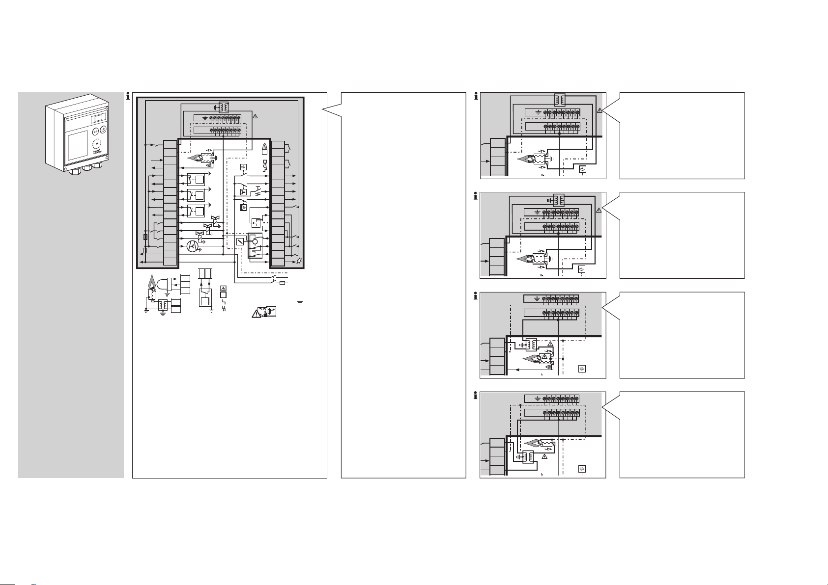
Anlage spannungsfrei schalten.
PE
N (L2)
L1 (L1)
F1
N
BCU 370..I1..U0
F1: T 5A H
IEC 60127-2/5
3
545471
9
PE
V1
V2
V3
M
3PS
19 17 18 20 21 22 23 24 25 26 27 28 29 30 31 32
3 1 2 4 5 6 7 8 9 10 11 12 13 14 15 16
230 V
BCU 370..D3
0➞90°
90°➞0
1
2
3
UVS
= Limits
= Start
= Alarm
= Reset
ϑ
L1, L2 = Live
N = Neutral
PE = Ground
p
Gas
min.
p
Gas
max.
N 16
13 14 15
p
Air
p
e
/2
11 p 12
I
Z
BCU 370..I2
1917 18 20 21 22 23 24 25 26 27 28 29 30 31 32
BCU 370..I1..U0
1917 18 20 21 22 23 24 25 26 27 28 29 30 31 32
BCU 370..I1..U0
1917 18 20 21 22 23 24 25 26 27 28 29 30 31 32
BCU 370..I3
1917 18 20 21 22 23 24 25 26 27 28 29 30 31 32
Kunststoffverschraubungen mit
Mehrfach-Kabeldurchlässen benutzen.
Gute Schutzleiterverbindung an der
BCU und am Brenner herstellen.
Verdrahten nach Schaltbild.
Disconnect the system from the
electrical power supply.
Use plastic cable glands with mul-
tiple cable grommet.
Ensure a good PE (ground) wire
connection to the BCU and burner.
Wire as shown on the circuit diagram.
Mettre l’installation hors tension.
Utiliser des presse-étoupes mul-
tiples en plastique.
Raccorder correctement le
conducteur de protection sur le
BCU et sur le brûleur.
Câbler selon le schéma de câ-
blage.
Installatie spanningsvrij maken.
Plastic wartels M20 met meervou-
dige kabeldoorvoer gebruiken.
Goede aardleiding op de BCU en
op de brander aansluiten.
Bedraden volgens het schakel-
schema.
Togliere la tensione dall’impianto.
Utilizzare collegamenti a vite in
plastica con passacavo multiplo.
Eseguire un buon collegamento
dei conduttori di protezione sulla
BCU e sul bruciatore.
Cablare seguendo lo schema.
Desconectar y dejar sin tensión la
instalación.
Utilizar racores roscados de plás-
tico con pasacables múltiple.
Establecer una buena conexión
del cable de tierra con el BCU y
el quemador.
Cablear según el esquema de co-
nexiones.
BCU 370
Integrierte Zündeinheit
BCU 370..I1, einpolige Zündung
Integrated ignition unit
BCU 370..I1, single-pole ignition
Transformateur d’allumage intégré
BCU 370..I1, allumage unipolaire
Geïntegreerde ontsteker
BCU 370..I1, eenpolige ontsteking
Unità di accensione integrata
BCU 370..I1, accensione unipolare
Unidad de encendido integrada
BCU 370..I1, encendido monopolar
V
V
13 14 15 16
V
V
- 8 -
PE
N
Z
13 14 15 16
13 14 15 16
13 14 15 16
Z
PE
N
Z
Z
PE
N
Z
I
PE
N
Z
Integrierte Zündeinheit
BCU 370..I2, zweipolige Zündung
Integrated ignition unit
BCU 370..I2, double-pole ignition
Transformateur d’allumage intégré
BCU 370..I2, allumage bipolaire
Geïntegreerde ontsteker
BCU 370..I2, dubbelpolige ontsteking
Unità di accensione integrata
BCU 370..I2, accensione bipolare
Unidad de encendido integrada
BCU 370..I2, encendido bipolar
Integrierte Zündeinheit
BCU 370..I3, zweipolige Zündung mit Mittelabgriff
Integrated ignition unit
BCU 370.. I3, double-pole ignition with centre tap
Transformateur d’allumage intégré
BCU 370..I3, allumage bipolaire avec point milieu
Geïntegreerde ontsteker
BCU 370..I3, dubbelpolige ontsteking met
middelste aansluiting
Unità di accensione integrata
BCU 370..I3, accensione bipolare con derivazione centrale
Unidad de encendido integrada
BCU 370..I3, encendido bipolar con toma central
Externe Zündung
BCU 370, Zweielektrodenbetrieb
External ignition
BCU 370, double-electrode operation
Transformateur d’allumage externe
BCU 370, contrôle deux électrodes
Externe ontsteking
BCU 370, bedrijf met twee elektroden
Accensione esterna
BCU 370, funzionamento bielettrodo
Encendido externo
BCU 370, operación con dos electrodos
Externe Zündung
BCU 370, Einelektrodenbetrieb
External ignition
BCU 370, single-electrode operation
Transformateur d’allumage externe
BCU 370, contrôle monoélectrode
Externe ontsteking
BCU 370, bedrijf met één elektrode
Accensione esterna
BCU 370, funzionamento monoelettrodo
Encendido externo
BCU 370, operación con un electrodo
Page 9
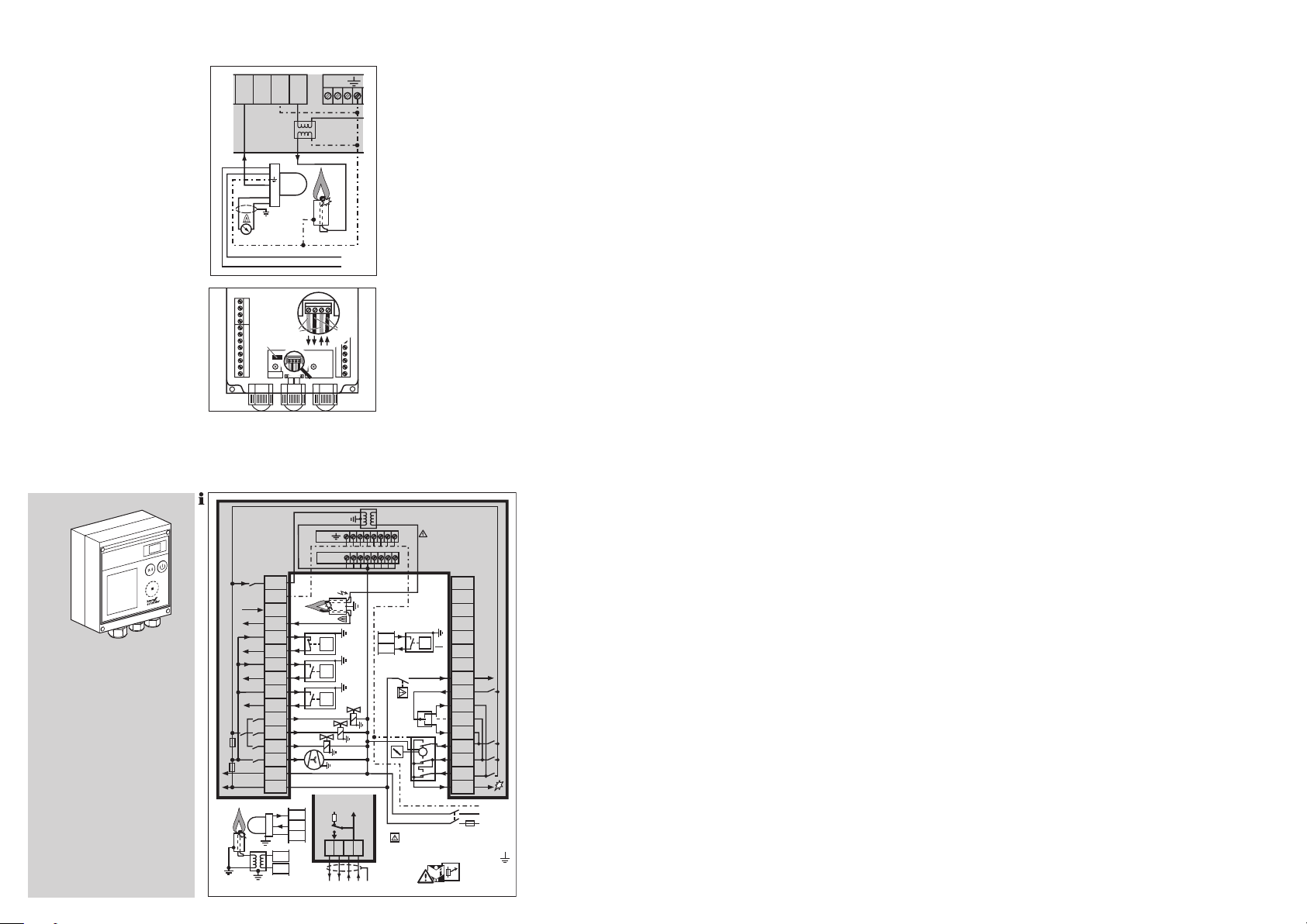
BCU 370..U1 mit UV-Überwa-
35455276
PE
N (L2)
L1 (L1)
F1
N
BCU 370..I1..U0..B1
F1: T 5A H
IEC 60127-2/5
PE
V1
V2
V3
M
3PS
24 25 26 27 28 29 30 31 32
31 2 4 5 6 7 8 9 10 11 12 13 14 15 16
230 V
0➞90°
90°➞0
= Limits
L1, L2 = Live
N = Neutral
PE = Ground
p
Gas
min.
p
Gas
max.
p
Air
BCU 370..B1
PROFIBUS DP
OFF
ON
BB A A
BCU 370..D3
p
e
2
11
p
12
I
Z
1
2
3
UVS
N 16
1314 15
0 V
24 V
+–
0–20 mA
13 14 15 16 PE
UVD1
1
2
4
3
5
6
1 2 3 4 5
6
7 8 9 10 11 12
21 22 23 24 25
26
27 28 29 30 31 32
C
B
A
chung für Dauerbetrieb mit UVSonde UVD 1
24 V-Versorgung und Stromaus-
gang von der UV-Sonde UVD 1
im Unterteil der BCU 370 separat
verdrahten.
Leitungslänge UVD 1 bis BCU 370
< 5 m.
Der Stromausgang 0 bis 20 mA
wird zur Anzeige des Flammensignals genutzt.
Der 0 bis 20 mA-Stromausgang
ist für den normalen Betrieb nicht
erforderlich.
Für das Analogsignal von der
BCU 370 zur Schaltwarte geschirmte Leitung verwenden.
BCU 370..B1 mit PROFIBUS DP
Abschlusswiderstände C beim
ersten und letzten Teilnehmer im
Segment einschalten.
Datenleitungen A und B an den
Klemmen nicht vertauschen.
Schirm beidseitig und großflächig
mit Schirmschelle verbinden.
Auf Potenzialausgleich zwischen
den Geräten achten.
Sicherheitskette separat verdrah-
ten.
An die Klemmen 17 bis 23 darf kei-
ne Spannung gelegt werden. Die
BCU kann sonst zerstört werden.
BCU 370..B1
BCU 370..U1 with UV control for
continuous operation with UV
sensor UVD 1
Wire 24 V supply and current out-
put from UV sensor UVD 1 separately in the lower section of the
BCU 370.
Cable length UVD 1 to BCU 370
< 5 m.
The 0 to 20 mA current output is
used to display the flame signal.
The 0 to 20 mA current output is
not required for normal operation.
Use a shielded cable for the ana-
logue signal from the BCU 370 to
the control room.
BCU 370..B1 with PROFIBUS DP
Switch on the terminal resistors C
on the first and last station in the
segment.
Do not reverse data cables A and
B on the terminals.
Connect the shield on both sides
and over a wide area with shield
clips.
Ensure an equipotential bond
between the units.
Wire safety interlocks separately.
No voltage must be connected to
terminals 17 to 23. Otherwise, the
BCU may be damaged.
BCU 370..U1 avec contrôle par
cellule UV pour fonctionnement
continu avec cellule UV UVD 1
Câbler séparément l’alimentation
24 V et la sortie de courant de la
cellule UV UVD 1 dans le bloc inférieur du BCU 370.
Longueur de câble UVD 1 jusqu’au
BCU 370 < 5 m.
La sortie de courant 0 – 20 mA est
utilisée pour l’affichage du signal
de flamme.
La sortie de courant 0 – 20 mA n’est
pas nécessaire pour le service normal.
Pour le signal analogique du BCU
370 en direction de la salle de commande, utiliser un câble blindé.
BCU 370..B1 avec PROFIBUS DP
Raccorder les résistances termi-
nales C dans le segment pour les
premier et dernier postes.
Ne pas inverser les câbles de don-
nées A et B aux bornes.
Raccorder le blindage des deux
côtés et sur une grande surface
avec des colliers blindés.
Vérifier la compensation de poten-
tiel entre les appareils.
Câbler séparément la chaîne de
sécurité.
Aucune tension ne doit être ap-
pliquée au niveau des bornes
17 à 23. Ceci serait susceptible
d’endommager le BCU.
BCU 370..U1 met UV-bewaking
voor continubedrijf met UV-sonde
UVD 1
24 V voorziening en stroomuitgang
van de UV-sonde UVD 1 in het
onderdeel van de BCU 370 apart
bedraden.
Kabellengte UVD 1 tot BCU 370
< 5 m.
De stroomuitgang 0 tot 20 mA
wordt voor de indicatie van het
vlamsignaal gebruikt.
De 0 tot 20 mA stroomuitgang is
voor de normale werking niet vereist.
Voor het analoge signaal van de
BCU 370 naar de schakelcentrale
een afgeschermde leiding gebruiken.
BCU 370..B1 met PROFIBUS DP
Afsluitweerstanden C bij de eerste
en laatste deelnemer in het segment inschakelen.
Datalijnen A en B op de klemmen
niet onderling verwisselen.
Afscherming aan beide zijden en
over een zo groot mogelijk oppervlak met schermbeugels verbinden.
Op potentiaalvereffening tussen de
apparaten letten.
Voorwaardencircuit apart bedra-
den.
Aan de klemmen 17 tot 23 mag
geen spanning worden gelegd.
Anders kan de BCU beschadigd
raken.
BCU 370..U1 con controllo UV per
funzionamento continuo con sonda UV UVD 1
Cablare separatamente l’alimen-
tazione 24 V e l’uscita di corrente
della sonda UV UVD 1 nella parte
inferiore della BCU 370.
Lunghezza conduttore UVD 1 fino
a BCU 370 < 5 m.
L’uscita di corrente da 0 a 20 mA è
utilizzata per visualizzare il segnale
di fiamma.
Per il funzionamento normale non
si richiede l’uscita di corrente da 0
a 20 mA.
Per il segnale analogico della
BCU 370 alla sala comandi utilizzare un conduttore schermato.
BCU 370..B1 con PROFIBUS DP
Attivare le resistenze di chiusura C
sul primo e sull’ultimo utente del
segmento.
Non scambiare i conduttori di dati,
A e B, sui morsetti.
Collegare lo schermo su entrambi
i lati e per un ampio tratto con le
relative fascette.
Verificare l’equipotenzialità tra gli
apparecchi.
Cablare la catena dei dispositivi di
sicurezza separatamente.
Sui morsetti da 17 a 23 non deve
esserci tensione. Altrimenti la BCU
può subire danni irreparabili.
.
BCU 370..U1 con control de llama
mediante la sonda UV UVD 1 para
funcionamiento continuo
Cablear la alimentación 24 V y la
salida de corriente de la sonda UV
UVD 1 por separado en la parte
inferior del BCU 370.
Longitud del cable de la UVD 1
hasta el BCU 370 < 5 m.
La salida de corriente 0 – 20 mA
sirve para la indicación de la señal
de llama.
La salida de corriente 0 – 20 mA
no es necesaria para el funciona-
miento normal.
Utilizar cable blindado para la señal
analógica del BCU 370 hasta el
puesto de mando.
BCU 370..B1 con PROFIBUS DP
Conectar resistencias terminales C
en el primer y en el último disposi-
tivos del segmento.
No intercambiar los cables de da-
tos A y B en los bornes.
Conectar la pantalla con abraza-
deras de pantalla a ambos lados
y con gran superficie.
Prestar atención a la conexión equi-
potencial entre los dispositivos.
Cablear la cadena de seguridad
por separado.
No se debe conectar ninguna
tensión en los bornes 17 hasta
23, pues de lo contrario se puede
destruir el BCU.
- 9 -
Page 10

BCU 370 mit Stellantrieb IC 20/IC 20..E
IC 20:
Der „Zu-Kontakt“ des externen
Drei-Punkt-Schritt-Reglers (3PS)
kann an Klemme 26 oder 27 angeschlossen werden.
Klemme 26: Der Regler arbeitet
zwischen Auf- und Zünd-Position.
Klemme 27: Der Regler arbeitet
zwischen Auf- und Zu-Position.
ACHTUNG! Die Eingänge für die
externe Klappensteuerung durch
den Regler, Klemme 26, 27, 28,
dürfen nur bestromt werden, wenn
am Ausgang Reglerfreigabe, Klemme 25, Spannung anliegt.
BCU 370
IC 20/IC 20..E
0➔90°
BCU 370
90°➔0
BCU 370 with actuator IC 20/IC 20..E
IC 20:
The “Close contact” of the external
three-point step controller (3PS)
can be connected to terminal 26
or 27.
Terminal 26: the controller oper-
ates between the Open and Ignition positions.
Terminal 27: the controller op-
erates between the Open and
Closed positions.
CAUTION! The inputs for the external valve control by the controller,
terminals 26, 27, 28, may only be
connected to the power supply, if
voltage is supplied to the Controller
enable signal output, terminal 25.
BCU 370 avec servomoteur
IC20 / IC 20..E
IC 20:
Le «contact fermeture» du régula-
teur progressif trois points externe
(3PS) peut être raccordé à la borne
26 ou 27.
Borne 26 : le régulateur fonctionne
entre la position ouverture et la position d’allumage.
Borne 27 : le régulateur fonctionne
entre les positions ouverture et fermeture.
ATTENTION ! Les entrées pour la
commande clapet externe via le régulateur, bornes 26, 27, 28, peuvent
être alimentées uniquement si la sortie d’autorisation régulation, borne
25, est sous tension.
BCU 370 met stelaandrijving
IC20/IC 20..E
IC 20:
Het “Dicht” contact van de externe
driepunts stappenregelaar (3PS)
kan op klem 26 of 27 worden
aangesloten.
Klem 26: de regelaar werkt tussen
de positie Open en Ontsteking.
Klem 27: de regelaar werkt tussen
de positie Open en Dicht.
ATTENTIE! Op de ingangen voor de
externe kleppenbesturing door de
regelaar, klemmen 26, 27, 28, mag
alleen dan stroom worden aangesloten wanneer er op de uitgang
vrijgave regelaar, klem 25, spanning
aanwezig is.
BCU 370
90°➔0
0➔90°
BCU 370 con servomotore
IC20/IC 20..E
IC 20:
Il “contatto off” del regolatore a
passi a tre punti (3PS), esterno,
può essere collegato al morsetto
26 o 27.
Morsetto 26: il regolatore lavora
tra la posizione “on” e la posizione
“accensione”.
Morsetto 27: il regolatore lavora
tra la posizione “on” e la posizione
“off”.
ATTENZIONE! Le entrate per il comando valvole esterno dal regolatore, morsetti 26, 27, 28, possono es-
sere alimentate solo se si dà tensione
all’uscita del via libera al regolatore,
morsetto 25.
BCU 370 con servomotor
IC20 / IC 20..E
IC 20:
El “contacto Cerrar” del regulador
progresivo de tres puntos externo
(3PS) se puede conectar al borne
26 ó al 27.
Borne 26: el regulador trabaja
entre las posiciones Abierto y En-
cendido.
Borne 27: el regulador trabaja
entre las posiciones Abierto y Ce-
rrado.
¡ATENCIÓN! A las entradas para el
mando externo de la válvula de mariposa a través del regulador, bornes
26, 27, 28, sólo se les puede aplicar
corriente cuando haya tensión en la
salida de autorización del regulador
de temperatura, borne 25.
BCU 370
3PS
L1 (L1)
N (L2)
PE
0°
OUT
20 19
IN
18
D
90° ➔ 0
3 2 1
4
0 ➔ 90°
PE
vfdfgdfxbhgd
vfdsgfdbgfb gfhff
vfdsgfdbgfb gfh
vfds
hlkjsgfdbgfb gfhfghgf
vfdg
vfdsgfngfdbgfb gfhgf
vfdsgfdbgfb
vfdsfsdvfd gfhfg
vfdsfdb
bgfb gfhf
gfb gfhfghgf
vfdb
gfb gfhfghgf
gfdb
gfhfg
gfb gfhfg
gfhfghgf
gfhf
gfh
IC 20
gf
fghgf
0
90°
16
67 4812 1115 13
3
vfdsfsdvfd gfhfg
gf
vfdsgfdbgfb gfhff
bgfb gfhf
vfdfgdfxbhgd
vfdsgfdbgfb gfhfghgf
gfb gfhfghgf
vfdb
gfb gfhfghgf
gfdb
vfds
dbgfb gfhfghgf
hlkjsgf
vfdg
gfhfg
vfdsgfngfdbgfb gfhgf
vfdsgfdbgfb
vfdsfdbgfb gfhfg
gfhfghgf
gfhf
gfh
90°
17
16
13
15
+ +
A
12 11
OK
5
6748
90°
➔
0°
3 2 1
0°
➔
90°
PE
L1 (L1)
N (L2)
PE
IC 20..E
- 10 -
Page 11

Einstellen
Änderung der Voreinstellungen
Es kann in bestimmten Fällen nötig
sein, die Voreinstellungen zu verändern. Mit Hilfe der separaten Software BCSoft und einem PC-OptoAdapter ist es möglich, einige Parameter an der BCU zu modifizieren. Wie
z. B. die Vorspülzeit oder das Verhalten bei Flammenausfall.
Einstellung der Geräteparame-
ter – siehe beigelegten Lieferschein.
Die Software und der Adapter sind
als Zubehör erhältlich – siehe Kapitel „Zubehör“.
ACHTUNG! Werden Parameter
geändert:
Mit der Protokollfunktion in der BCSoft die Änderungen dokumentieren und der Anlagendokumentation
beifügen.
Aufkleber „Achtung, geänderte Parameter!“ am Gehäuse aufkleben.
Bei Ersatzbestellungen für eine
BCU mit geänderten Parametern,
die Angaben aus dem Protokoll
entnehmen.
Die Voreinstellungen sind mit
einem werksseitig eingestellten
Kennwort gesichert – siehe Lieferschein.
Das geänderte Kennwort kann
der Endkunde der Anlagendokumentation entnehmen oder beim
Systemlieferanten erfragen.
Wird die BCU 370 zur Überprüfung
an Elster Kromschröder geschickt,
erfolgt die Rücklieferung mit der
ursprünglichen Werksparametrierung.
D-49018 Osnabrück, Germany
Achtung, geänderte Parameter!
Die Angaben auf dem Typenschild
gelten nicht mehr in vollem Umfang.
Aktuelle Parameter direkt auslesen.
Important, changed parameters!
The details on the type label are no
longer completely accurate. Read the
current parameters direct from the
unit.
Attention, paramètres modifiés !
Les informations figurant sur la plaque
signalétique ne sont plus valables
dans leur intégralité. Veuillez vous
référer directement aux paramètres
actualisés.
Adjustment
Changing the pre-settings
In certain cases, it may be necessary
to change the pre-settings. Using the
separate software package BCSoft
and a PC opto-adapter, it is possible
to modify certain parameters on the
BCU, such as pre-purge times or
the behaviour in the event of a flame
failure.
Adjustment of unit parameters –
see enclosed delivery note.
The software package and the
adapter are available as accessories – see section entitled “Accessories”.
CAUTION! If parameters are
changed:
Document the changes in BCSoft
using the protocol function and
enclose the protocol with the plant
documentation.
Stick the “Important, changed parameters!” label on the housing.
If a replacement is ordered for a
BCU with changed parameters, refer
to the protocol for details.
The pre-settings are secured with
a password which is set at the factory – see delivery note.
The end customer can look up the
changed password in the plant
documentation or ask the system
supplier.
If the BCU 370 is sent to
ElsterKromschröder for inspection, it is returned with the original
factory parameterization.
Réglages
Modification des préréglages
Dans certains cas, il peut être nécessaire de modifier les préréglages. À
l’aide du logiciel indépendant BCSoft
et d’un adaptateur optique, certains
paramètres du BCU peuvent être modifiés. Comme par exemple le temps
de pré-ventilation ou le comportement
en cas de disparition de flamme.
Réglage des paramètres de l’ap-
pareil – voir le bon de livraison
fourni.
Le logiciel et l’adaptateur sont
disponibles comme accessoires –
voir le chapitre «Accessoires».
ATTENTION ! Si des paramètres
sont modifiés :
Indiquer les modifications dans le
BCSoft à l’aide de la fonction de
protocole et joindre à la documentation sur l’installation.
Appliquer l’étiquette adhésive «Attention, paramètres modifiés !» sur
le boîtier.
Suivre les indications du protocole
pour les commandes supplémentaires d’un BCU avec paramètres
modifiés.
Les préréglages sont protégés
par un mot de passe paramétré
en usine – voir le bon de livraison.
Le client final peut consulter le mot
de passe modifié dans la documentation sur l’installation ou en
faire la demande auprès du fournisseur du système.
Si le BCU 370 est envoyé à
Elster Krom schröder pour
contrôle, le retour s’effectuera
avec le paramétrage d’origine en
usine.
Instellen
Voorinstelling veranderen
Het kan in bepaalde gevallen nodig
zijn om de voorinstellingen te veranderen. Met behulp van de afzonderlijke
software BCSoft en een PC optoadapter is het mogelijk om enige parameters van de BCU te modificeren,
zoals bijvoorbeeld de voorspoeltijd of
het gedrag bij vlamstoring.
Instelling van de hardwareparame-
ters – zie bijgevoegd afleveringsbewijs.
De software en de adapter zijn
als toebehoren verkrijgbaar – zie
hoofdstuk “Toebehoren”.
ATTENTIE! Als er parameters gewijzigd worden:
Met de rapportagefunctie van
BCSoft de veranderingen documenteren en aan de documentatie
van het apparaat toevoegen.
De sticker “Attentie, gewijzigde
parameters!” op de behuizing aanbrengen.
Bij bestelling van reserveonderdelen
voor een BCU met gewijzigde parameters de gegevens uit het rapport
overnemen.
De fabrieksinstelling is met een in
de fabriek ingesteld wachtwoord
beveiligd – zie afleveringsbewijs.
Het veranderde wachtwoord kan
de eindklant in de documentatie
van het apparaat nalezen of bij de
systeemleverancier opvragen.
Wordt de BCU 370 ter controle
aan Elster Kromschröder opgestuurd, wordt deze met de oorspronkelijke fabrieksparametratie
geretourneerd.
Regolazione
Modifica dei parametri preimpostati
In determinati casi può essere necessario modificare i parametri preimpostati. Per mezzo del software separato
BCSoft e di un adattatore ottico da
interfacciare con un PC è possibile
modificare alcuni parametri sulla
BCU. Ad es. il tempo di prelavaggio
o il comportamento in caso di spegnimento della fiamma.
Impostazione dei parametri
dell’apparecchio – vedi bolla di
accompagnamento allegata.
Il software e l’adattatore sono for-
niti come accessori – vedi capitolo
“Accessori”.
ATTENZIONE! Se si modificano dei
parametri:
Documentare le variazioni nel
BCSoft con la funzione Protocollo e allegare alla documentazione
dell’impianto.
Applicare sul corpo l’etichetta adesiva “Attenzione, parametri modificati!”.
In caso di ordini di pezzi sostitutivi
per una BCU con parametri modificati, riportare le indicazioni tratte
dal protocollo.
I parametri preimpostati sono pro-
tetti da una password impostata
dal costruttore – vedi bolla di accompagnamento.
Il cliente finale può desumere la
password modificata dalla documentazione dell’impianto oppure
richiederla al fornitore dell’impianto.
Se la BCU 370 viene spedita a
ElsterKromschröder per la verifica,
verrà rinviata con la definizione dei
parametri originale del costruttore.
Ajuste
Modificación de los preajustes
En determinados casos puede ser
necesario modificar los preajustes.
Con ayuda del software separado
BCSoft y de un adaptador optoacoplado para PC, es posible modificar
algunos parámetros en el BCU. Como
p. ej. el tiempo de barrido previo o
el comportamiento en caso de fallo
de llama.
Ajuste de los parámetros del dis-
positivo – ver el albarán de entrega
adjunto.
El software y el adaptador se su-
ministran como accesorios – ver
capítulo “Accesorios”.
¡ATENCIÓN! Si se modifican parámetros:
Documentar las modificaciones con
la función de protocolo del BCSoft
y agregarlas a la documentación de
la instalación.
Pegar sobre la carcasa la etiqueta
adhesiva “Atención, parámetros
modificados”.
Cuando se realicen pedidos de
reposición para un BCU con parámetros modificados, indicar las
especificaciones del protocolo.
Los ajustes previos están protegi-
dos de fábrica con una contraseña – ver albarán de entrega.
La contraseña modificada la pue-
de obtener el cliente final de la
documentación de la instalación
o la puede preguntar al proveedor
del sistema.
Si se envía el BCU 370 a
Elster Krom schröder para su
comprobación, se devolverá con la
parametrización original de fábrica.
- 11 -
Page 12

In Betrieb nehmen
ACHTUNG! Die Inbetriebnahme ist
so lange untersagt, bis festgestellt
wird, dass die Maschine, in die das
Gerät eingebaut werden soll, den
Bestimmungen der zutreffenden
Richtlinien entspricht.
BCU 370 ohne Profibus
Verdrahtung überprüfen.
Anlage einschalten.
Die Anzeige zeigt
Gas-Absperrhahn öffnen.
4 BCU einschalten.
Die BCU ist in Anlaufstellung/
Stand by. Die Anzeige zeigt 00.
5
Programmablauf für den Brenner
starten: Spannung an Klemme 21
(ϑ) anlegen.
BCU 370
.
- -
Commissioning
CAUTION! Commissioning is pro-
hibited until it has been established
that the machine where the unit is to
be installed complies with the terms
of the relevant Directives.
BCU 370 without Profibus
Check the wiring.
Switch on the system.
The display indicates
Open the gas shut-off valve.
0 0
01
P1 A2
A1 08
t
t
E
GV
t
PV
4 Switch on the BCU.
The BCU is in start-up position/
standby. The display indicates 00.
5
Start the program for the burner:
apply voltage to terminal 21 (ϑ).
03 04
t
VZ
t
Z1
t
SA1
06H0 0500
t
t
FS1
SA2
Mise en service
ATTENTION ! La machine, sur la-
quelle l’appareil doit être monté, ne
pourra être mise en service qu’après
avoir constaté que celle-ci répond
aux exigences des directives applicables.
BCU 370 sans Profibus
Vérifier le câblage.
Mettre l’installation sous tension.
.
- -
H807
t
t
FS2
RF
L’affichage indique
Ouvrir le robinet d’arrêt de gaz.
4 Mettre le BCU sous tension.
Le BCU est en position de dé-
marrage / attente / standby. L’affichage indique 00.
5 Lancer le programme du brûleur :
mettre sous tension la borne 21
(ϑ).
88
1
24
11 DG
max.
9
DG
min.
30
90° ➔ 0
29
0 ➔ 90°
31
32
7 DL
ϑ
21
3
16
13
V1
4
5 V2
6 V3
17-18
19-20
.
- -
t
In bedrijf stellen
ATTENTIE! De inbedrijfstelling is zo-
lang verboden, totdat vastgesteld
wordt dat de installatie, waarin het
apparaat ingebouwd moet worden,
aan de bepalingen van de toepasselijke richtlijnen voldoet.
BCU 370 zonder profibus
Bedrading controleren.
Installatie inschakelen.
Het display toont
Gaskraan openen.
4 BCU inschakelen.
De BCU is in aanloopstand/stand-
by. Het display toont 00.
5
Programmaloop voor de brander
starten: spanning op klem 21 (ϑ)
geven.
.
- -
Messa in servizio
ATTENZIONE! La messa in funzio-
ne è vietata, finché non si accerta
che la macchina su cui va montato
l’apparecchio soddisfa i requisiti
delle direttive corrispondenti.
BCU 370 senza Profibus
Controllare il cablaggio.
Mettere in funzione l’impianto.
L’indicatore riporta
Aprire il rubinetto del gas.
4 Attivare la BCU.
La BCU è in posizione di avvia-
mento/standby. L’indicatore riporta 00.
5
Avviare il programma per il bruciatore: dare tensione al morsetto 21
(ϑ).
.
- -
Puesta en funcionamiento
¡ATENCIÓN! Está prohibida la
puesta en servicio, hasta que no se
haya confirmado que, la máquina en
la que se debe instalar el dispositivo,
cumple las directivas aplicables.
BCU 370 sin Profibus
Comprobar el cableado.
Conectar la instalación.
El indicador muestra
Abrir la válvula de interrupción de gas.
4 Conectar el BCU.
El BCU está en posición de arran-
que/espera/standby. El indicador
muestra 00.
5 Iniciar el desarrollo del programa
para el quemador: aplicar tensión
al borne 21 (ϑ).
.
- -
Normaler Anlauf mit Vorspülung
Parameter 6 = 1: Vorspülung bei jedem Anlauf.
Parameter 22 > 0 s: Die Einschalt-
verzögerungszeit tE läuft und die
Anzeige zeigt
Parameter 20 > 0 s: Die Gebläse-
vorlaufzeit t
ge zeigt
Die Luftklappe fährt in Auf-Position
und die Anzeige zeigt
Die Vorspülzeit tPV läuft. Die Anzei-
ge zeigt
Die Luftklappe fährt in Zünd-Posi-
tion und die Anzeige zeigt
Parameter 21 > 0 s: Die Vorzünd-
zeit tVZ läuft und die Zündeinheit
wird aktiviert. Die Anzeige zeigt
Die erste Sicherheitszeit t
läuft.
Mit Beginn der ersten Sicherheits-
zeit öffnen die Gas-Magnetventile
V1 und V2. Der Zündbrenner/
Brenner wird gezündet.
.
H0
läuft und die Anzei-
GV
.
01
.
P1
A1
.
A2
SA1
.
03
04
Normal start-up with pre-purge
Parameter 6 = 1: pre-purge on each
start-up.
Parameter 22 > 0 s: the switch-on
delay time tE starts to elapse and
the display indicates
Parameter 20 > 0 s: the fan run up
time tGV starts to elapse and the
display indicates
The butterfly valve for air moves to
the Open position and the display
indicates
The pre-purge time tPV starts to
elapse. The display indicates
The butterfly valve for air moves
to the Ignition position and the
.
display indicates
Parameter 21 > 0 s: the pre-igni-
tion time tVZ starts to elapse and
the ignition unit is activated. The
display indicates
The first safety time t
to elapse.
Gas solenoid valves V1 and V2 open
as the first safety time starts to elapse.
The pilot burner/burner is ignited.
A1
.
01
A2
03
.
.
.
SA1
.
H0
04
Démarrage normal avec pré-ventilation
Paramètre 6 = 1 : pré-ventilation à
chaque démarrage.
Paramètre 22 > 0 s : la temporisa-
tion de mise en marche tE débute
et l’affichage indique
Paramètre 20 > 0 s : le temps de
démarrage ventilateur tGV débute
et l’affichage indique
Le clapet d’air se place en position
ouverture et l’affichage indique
Le temps de pré-ventilation tPV débute. L’affichage indique
.
Le clapet d’air se place en position
P1
d’allumage et l’affichage indique
Paramètre 21 > 0 s : le temps de
pré-allumage tVZ débute et le transformateur d’allumage est activé.
L’affichage indique
Le premier temps de sécurité t
débute.
starts
04
Les électrovannes gaz V1 et V2
s’ouvrent lorsque le premier temps
de sécurité débute. Le brûleur
d’allumage/ le brûleur s’allume.
03
H0
01
.
P1
Normaal opstarten met voorspoeling
Parameter 6 = 1: voorspoeling bij
elke start.
Parameter 22 > 0 s: de inscha-
.
.
.
kelvertragingstijd t
display toont
Parameter 20 > 0 s: de ventilator-
voorlooptijd tGV loopt en het display toont
De luchtklep gaat in positie Open
.
en het display toont
A1
De voorspoeltijd tPV loopt. Het
display toont
De luchtklep gaat in de ontstekings-
.
positie en het display toont
A2
Parameter 21 > 0 s: de voorontste-
kingstijd tVZ loopt en de ontsteker
wordt geactiveerd. Het display
toont
.
03
De eerste veiligheidstijd t
SA1
loopt.
Aan het begin van de eerste
veiligheidstijd gaan de gasmagneetkleppen V1 en V2 open. De
aansteekbrander/brander wordt
ontstoken.
01
H0
P1
.
.
.
loopt en het
E
.
A1
SA1
Avvio normale con prelavaggio
Parametro 6 = 1: prelavaggio a ogni avvio.
Parametro 22 > 0 s: il tempo del
ritardo di accensione t
l’indicatore riporta
Parametro 20 > 0 s: il tempo di
precorsa soffiante t
l’indicatore riporta
La valvola dell’aria va in posizione
“on” e l’indicatore riporta
Il tempo di prelavaggio t
L’indicatore riporta
La valvola dell’aria va in posizione
“accensione” e l’indicatore riporta
.
A2
04
.
A2
Parametro 21 > 0 s: il tempo di
preaccensione tVZ scorre e si attiva
l’unità di accensione. L’indicatore
riporta
Il primo tempo di sicurezza t
04
Quando il primo tempo di sicurez-
za comincia a scorrere, si aprono
le valvole elettromagnetiche gas
V1 e V2. Si accende il bruciatore
pilota/bruciatore.
03
scorre.
.
H0
01
P1
.
GV
.
scorre e
E
scorre e
A1
scorre.
PV
.
Arranque normal con barrido previo
Parámetro 6 = 1: barrido previo a cada arranque.
Parámetro 22 > 0 s: está transcurrien-
do el tiempo de retardo de conexión
tE y el indicador muestra
Parámetro 20 > 0 s: está transcurriendo el tiempo de espera inicio barrido
previo tGV y el indicador muestra
La válvula de mariposa del aire va
.
a la posición de Abierto y el indicador muestra
Está transcurriendo el tiempo de barrido
previo tPV. El indicador muestra
La válvula de mariposa del aire va
a la posición de Encendido y el
indicador muestra
Parámetro 21 > 0 s: está transcu-
rriendo el tiempo de preencendido
tVZ y se activa la unidad de encendido. El indicador muestra
SA1
Está transcurriendo el primer tiem-
po de seguridad t
Al iniciarse el primer tiempo de seguridad se abren las válvulas electromagnéticas para gas V1 y V2. Se enciende
el quemador de encendido/quemador.
A1
.
A2
SA1
.
H0
.
01
.
P1
.
.
03
.
04
- 12 -
Page 13

Parameter 13 > 0 s: Die Flammen-
stabilisierungszeit t
Zündbrenner/Brenner läuft.
Parameter 14 > 0 s: Die zweite
Sicherheitszeit t
Mit Beginn der zweiten Sicherheits-
zeit öffnet das Gas-Magnetventil V3. Der Hauptbrenner wird gezündet. Wenn Parameter 27 = 0,
wird das Gas-Magnetventil V2
1 s vor Ende der zweiten Sicherheitszeit t
SA2
Zündbrenner abgeschaltet.
Parameter 15 > 0 s: Die Flammen-
stabilisierungszeit t
Hauptbrenner läuft.
Parameter 29 > 0 s: Die Verzöge-
rungszeit tRF
gabe läuft.
Die Reglerfreigabe
Brenner ist in Betrieb.
Das Anlaufsignal (ϑ) wird abge-
schaltet und Parameter 19 > 0 s:
Die Nachspülzeit tPN
Luftklappe fährt währenddessen in
die Zünd-Position, danach in die
Zu-Position. Anschließend verharrt
die BCU in der Anlaufstellung/
Stand by.
Werksseitig können bis zu 4 Anlaufversuche eingestellt sein. Das heißt,
nach einem erfolglosen Anlauf kann
die BCU bis zu dreimal den Brenner
neu starten, bevor eine Störabschaltung durchgeführt wird.
Achtung! Bei Geräten mit FM-Zu-
lassung ist maximal 1 Wiederanlauf
möglich.
Normaler Anlauf mit Vorspülung
und Dichtheitskontrolle
BCU 370..D3, Parameter 24 = 3:
Ist die BCU mit der Option Dicht-
heitskontrolle ..D3 ausgestattet,
läuft parallel zur Vorspülung die
Dichtheitskontrolle und überprüft
die Sicherheitsfunktion der GasMagnetventile.
Entfällt bei einem schnellen Anlauf
die Vorspülung, erfolgt die Dichtheitskontrolle während der Nachspülung.
Die Vorspül- und Nachspülzeit sind
≥ der Prüfdauer.
Prüfdauer t
p
für den
05
FS1
06
läuft.
SA2
geschlossen und der
für den
07
FS2
für die Reglerfrei-
H8
läuft. Der
08
läuft. Die
P9
bestimmen.
Parameter 13 > 0 s: the flame
proving period t
lot burner/burner starts to elapse.
Parameter 14 > 0 s: the second
safety time t
elapse.
The gas solenoid valve V3 opens
as the second safety time starts
to elapse. The main burner is ignited. If parameter 27 = 0, the gas
solenoid valve V2 is closed 1 s before the end of the second safety
time t
and the pilot burner is
SA2
switched off.
Parameter 15 > 0 s: the flame
proving period t
main burner starts to elapse.
Parameter 29 > 0 s: the delay time
H8
tRF
for the Controller enable
signal starts to elapse.
The controller enable process
is running. The burner is in operation.
The start-up signal (ϑ) is switched
off and parameter 19 > 0 s:
The post-purge time tPN
to elapse. The butterfly valve for
air moves to the Ignition position
during this time, then to the Closed
position. Next the BCU rests in the
start-up position/standby.
Up to four start-up attempts may be
set at the works. This means that,
after a failed start-up attempt, the
BCU can restart the burner up to
three times before a fault lock-out is
performed.
Attention! For units approved by
FM Approvals a maximum of 1 restart attempt is permitted.
Normal start-up with pre-purge
and tightness control
BCU 370..D3, parameter 24 = 3:
If the BCU is equipped with the
tightness control option ..D3, the
tightness test runs in parallel to
pre-purge and checks the safety
function of the gas solenoid valves.
Pre-purge is omitted during quick
start and the tightness test takes
place during post-purge.
The pre-purge and post-purge
times are ≥ the test period.
Determine test period t
SA2
FS1
FS2
05
06
for the pi-
starts to
07
for the
P9
starts
.
p
08
Paramètre 13 > 0 s : le temps de
stabilisation de flamme t
pour le brûleur d’allumage / brûleur
débute.
Paramètre 14 > 0 s : le second
temps de sécurité t
L’électrovanne gaz V3 s’ouvre
lorsque le second temps de sécurité débute. Le brûleur principal
s’allume. Lorsque le paramètre
27 = 0, l’électrovanne gaz V2 se
ferme 1 s avant la fin du second
temps de sécurité t
d’allumage s’arrête.
Paramètre 15 > 0 s : le temps de
stabilisation de flamme t
pour le brûleur principal débute.
Paramètre 29 > 0 s : le temps de
temporisation tRF
risation de la régulation débute.
L’autorisation de la régulation
mence. Le brûleur est en service.
Le signal de démarrage (ϑ) est
coupé et le paramètre 19 > 0 s :
le temps de post-ventilation tPN
débute. Pendant ce temps, le clapet d’air se place en position d’allumage, puis en position fermeture. Le
BCU demeure ensuite en position
de démarrage / attente.
Jusqu’à 4 tentatives d’allumage
peuvent être réglées en usine. Cela
signifie qu’après un échec du démarrage, le BCU peut essayer trois fois de
faire redémarrer le brûleur, avant de
déclencher une mise à l’arrêt.
Attention ! Pour les appareils bénéficiant d’une homologation FM,
un seul redémarrage est possible.
Démarrage normal avec préventilation et contrôle d’étanchéité
BCU 370..D3, paramètre 24 = 3 :
Si le BCU est équipé de l’option
contrôle d’étanchéité ..D3, le
contrôle d’étanchéité s’effectue
en parallèle à la pré-ventilation et
la fonction de sécurité des électrovannes gaz est vérifiée.
Si la pré-ventilation est supprimée
lors d’un démarrage rapide, le
contrôle d’étanchéité s’effectue
durant la post-ventilation.
Les temps de pré-ventilation et de
post-ventilation sont supérieurs ou
égaux à la durée d’essai.
Déterminer la durée d’essai t
06
SA2
et le brûleur
SA2
H8
pour l’auto-
FS1
débute.
FS2
08
- 13 -
Parameter 13 > 0 s: de vlamstabili-
05
satietijd t
brander/brander loopt.
Parameter 14 > 0 s: de tweede
veiligheidstijd t
Aan het begin van de tweede vei-
ligheidstijd gaat de gasmagneetklep V3 open. De hoofdbrander
wordt ontstoken. Als parameter 27
= 0, wordt de gasmagneetklep V2
1 s voor het einde van de tweede
veiligheidstijd t
aansteekbrander uitgeschakeld.
Parameter 15 > 0 s: de vlamsta-
bilisatietijd t
07
brander loopt.
Parameter 29 > 0 s: de vertra-
gingstijd t
regelaar loopt.
De vrijgave regelaar
com-
p
brander is in bedrijf.
Het aanloopsignaal (ϑ) wordt uitge-
schakeld en parameter 19 > 0 s:
De naspoeltijd tPN
P9
luchtklep gaat ondertussen in de
ontstekingspositie, daarna in de
positie Dicht. Vervolgens blijft de
BCU in de aanloopstand/stand-by.
In de fabriek kunnen max. 4 startpogingen ingesteld zijn. Dat wil zeggen
dat de BCU na het tevergeefs opstarten de brander hoogtuit drie keer
opnieuw kan starten. Daarna wordt
deze wegens storing uitgeschakeld.
Attentie! Bij apparatuur met FM
goedkeuring is maximaal 1 herstart
mogelijk.
Normaal opstarten met voorspoeling en lektest
BCU 370..D3, parameter 24 = 3:
Als de BCU met de optionele lek-
test ..D3 is uitgerust, loopt parallel met de voorspoeling de lektest
en controleert de veiligheidsfunctie
van de gasmagneetkleppen.
Als bij het snelle opstarten de voor-
spoeling vervalt, gebeurt de lektest
tijdens de naspoeling.
De voor- en naspoeltijd zijn ≥ de
tijdsduur van de test.
Tijdsduur van de test t
.
05
voor de aansteek-
FS1
SA2
SA2
07
FS2
H8
RF
06
loopt.
gesloten en de
voor de hoofd-
voor de vrijgave
08
loopt. De
P9
loopt. De
bepalen.
p
Parametro 13 > 0 s: il tempo di
stabilizzazione della fiamma t
per il bruciatore pilota/brucia-
05
tore scorre.
Parametro 14 > 0 s: il secondo tem-
po di sicurezza t
Quando il secondo tempo di sicu-
rezza comincia a scorrere, si apre
la valvola elettromagnetica gas V3.
Si accende il bruciatore principale.
In caso di parametro 27 = 0, la
valvola elettromagnetica gas V2 si
chiude 1 s prima dello scadere del
secondo tempo di sicurezza t
si spegne il bruciatore pilota.
Parametro 15 > 0 s: il tempo di
stabilizzazione della fiamma t
per il bruciatore principale
07
scorre.
Parametro 29 > 0 s: il tempo di
ritardo t
RF
regolatore scorre.
Il via libera del regolatore
re. Il bruciatore è in funzione.
Si spegne il segnale di avviamento
(ϑ) e parametro 19 > 0 s:
Il tempo di lavaggio tPN
Contestualmente la valvola dell’aria
va in posizione “accensione” e,
successivamente, in posizione
“off”. A questo punto la BCU rimane in posizione di avviamento/
standby.
La ditta produttrice ha previsto che si
possano programmare fino a 4 tentativi di avvio. Ciò significa che dopo
un’accensione non riuscita, la BCU
può avviare di nuovo il bruciatore per
tre volte prima che si attui un blocco
per guasto.
Attenzione! Su apparecchi con approvazione FM è possibile effettuare
max. 1 ritentativo.
Avvio normale con prelavaggio e
controllo di tenuta
BCU 370..D3, parametro 24 = 3:
Se la BCU è dotata dell’opzione
controllo di tenuta ..D3, tale controllo si svolge parallelamente al
prelavaggio e verifica la funzione
di sicurezza delle valvole elettromagnetiche gas.
Se in caso di avvio rapido il prela-
vaggio non ha luogo, il controllo di
tenuta avviene durante il lavaggio.
Il tempo di prelavaggio e di lavag-
gio sono ≥ al tempo di verifica.
Definire il tempo di verifica t
06
SA2
per il via libera del
H8
scorre.
08
scorre.
P9
SA2
scor-
.
p
FS1
FS2
Parámetro 13 > 0 s: está transcu-
rriendo el tiempo de estabilización
de llama t
de encendido/quemador.
Parámetro 14 > 0 s: está trans-
curriendo el segundo tiempo de
seguridad t
Al iniciarse el segundo tiempo de
seguridad se abre la válvula electromagnética para gas V3. Se
enciende el quemador principal.
Cuando el parámetro 27 = 0, se
cierra la válvula electromagnética
e
para gas V2 1 s antes de finalizar
el segundo tiempo de seguridad
t
SA2
de encendido.
Parámetro 15 > 0 s: está transcu-
rriendo el tiempo de estabilización
de llama t
principal.
Parámetro 29 > 0 s: está transcu-
rriendo el tiempo de retardo tRF
para la autorización del regulador de
temperatura.
Está funcionando la autorización del
regulador de temperatura
quemador está en funcionamiento.
Se desconecta la señal de arran-
que (ϑ) y el parámetro 19 > 0 s:
Está transcurriendo el tiempo de
barrido posterior tPN
tanto la válvula de mariposa del
aire va a la posición de Encendido
y, a continuación, a la posición de
Cerrado. Seguidamente el BCU permanece en la posición de arranque/
espera.
En fábrica pueden haberse ajustado
hasta 4 intentos de arranque. Es decir,
después de un arranque sin éxito, el
BCU puede encender de nuevo hasta
tres veces más el quemador, antes
de que se realice una desconexión
por avería.
¡Atención! En los dispositivos con
aprobación FM es posible realizar el
reencendido máximo una vez.
Arranque normal con barrido
previo y control de estanquidad
BCU 370..D3, parámetro 24 = 3:
Si el BCU está equipado con la
opción de control de estanquidad
..D3, el control de estanquidad se
realiza en paralelo al barrido previo
y comprueba la función de seguridad de las válvulas electromagnéticas para gas.
Si se prescinde del barrido previo
en un arranque rápido, el control
de estanquidad se realiza durante
el barrido posterior.
Tanto el tiempo de barrido previo
como el de barrido posterior son
≥ la duración del ensayo.
Determinar la duración del ensayo
tp.
05
para el quemador
FS1
06
.
SA2
y se desconecta el quemador
07
para el quemador
FS2
P9
H8
08
. El
. Mientras
Page 14

BCU 370..D3
L
pe × V
100 × 6,3
Undichtheiten werden für das Ven-
til V1 mit
V3 mit
Verkürzter Anlauf
Bei Geräten mit FM-Zulassung ist
keine Schnellstart-Funktion zulässig.
Der verkürzte Anlauf ist aktiviert,
wenn Parameter 6 = 0. Nach einer Regelabschaltung entfällt beim
nächsten Anlauf innerhalb 24 h die
Vorspülung.
Parameter 28 = 0:
BCU wartet in der Zünd-Position,
Parameter 28 = 1:
BCU wartet in der Zu-Position.
BCU 370..B1 mit PROFIBUS DP
Bei PROFIBUS-Geräten, BCU..B1,
wird zunächst der PROFIBUS DP in
Betrieb genommen.
Alle gerätespezifischen Parame-
ter für die BCU..B1 sind in einer
Gerätestammdaten-Datei (GSD)
gespeichert und als Diskette oder
Download verfügbar (siehe „Zubehör“).
GSD-Datei einlesen.
Die nötigen Schritte zum Einlesen
der Datei aus der Anleitung des
Automatisierungssystems entnehmen.
PROFIBUS DP mit den entspre-
chenden Tools des verwendeten
Automatisierungssystems konfigurieren.
Die BCU..B1 erkennt automatisch
die Baudrate – max. 1,5 Mbit/s.
und für die Ventile V2/
36
angezeigt.
37
Prüfvolumen/Test volume/Volume d’essai/Testvolume/Volume di prova/
Volumen de ensayo V
DN G F G F G F G F G F G F G F
10
15
20
25
40
50
65
80
100
125
150
200
G = Gewinde/Thread/Taraudage/Schroefdraad/Filetto/Rosca
F = Flansch/Flange/Bride/Flens/Flangia/Brida
Leakage is indicated by
valve V1 and
Quick start
For units approved by FM Ap-
provals no quick start function is
permitted.
Quick start is activated when
parameter 6 = 0. After controlled
shut-down, pre-purge is omitted on the next start-up within
24hours.
Parameter 28 = 0:
BCU waits in the Ignition position,
Parameter 28 = 1:
BCU waits in the Closed position.
BCU 370..B1 with PROFIBUS DP
On PROFIBUS units, BCU..B1, the
PROFIBUS DP must be commissioned first.
All the unit-specific parameters
for the BCU..B1 are saved in a
device master data file (GSD) and
are available as a diskette or to
download (see “Accessories”).
Copy the GSD file.
The steps required to copy the file
are described in the instructions
for the automation system.
Configure the PROFIBUS DP us-
ing the appropriate tools for the
automation system you are using.
The BCU..B1 will automatically
identify the baud rate – max.
1.5 Mbit/s.
[l]
p
0 0,5 1 1,5 2 2,5 3
0,01 0,06 0,1 0,16 0,2 0,26 0,3
0,07 0,17 0,27 0,37 0,47 0,57 0,67
0,12 0,27 0,42 0,57 0,72 0,87 1,0
0,2 0,45 0,7 1,0 1,2 1,5 1,7
0,5 0,7 1,2 1,4 1,8 2,0 2,5 2,7 3,1 3,3 3,7 4,0 4,3 4,5
0,9 1,2 2,0 2,2 3,0 3,2 4,0 4,2 5,0 5,2 6,0 6,2 7,0 7,2
2,0 3,7 5,3 7,0 8,6 10,0 12,0
4,0 6,3 8,8 11,0 14,0 16,0 19,0
8,3 12,0 16,0 20,0 24,0 28,0 32,0
13,6 20,0 26,0 32,0 38,0 44,0 50,0
20,0 29,0 38,0 47,0 55,0 64,0 73,0
42,0 58,0 74,0 90,0
36
for valves V2/V3.
37
L [m]
105,0
Le manque d’étanchéité est in-
for
diqué par le chiffre
vanne V1 et par le chiffre
les vannes V2/V3.
Démarrage rapide
Pour les appareils bénéficiant
d’une homologation FM, la fonction démarrage rapide n’est pas
admise.
Le démarrage rapide est activé
lorsque paramètre 6 = 0. Après
arrêt régulation, la pré-ventilation
est supprimée lors du prochain
démarrage sous 24 h.
Paramètre 28 = 0 :
le BCU attend en position d’allu-
mage.
Paramètre 28 = 1 :
le BCU attend en position fermeture.
BCU 370..B1 avec PROFIBUS DP
Sur les appareils avec PROFIBUS,
BCU..B1, le PROFIBUS DP doit
également être mis en service.
Tous les paramètres spécifiques
au BCU..B1 sont enregistrés dans
un fichier de données de base de
l’appareil (GSD) et disponibles sur
disquette ou à télécharger (voir
«Accessoires»).
Lire le fichier GSD.
Les étapes requises pour lire le
fichier sont indiquées dans les ins-
tructions d’utilisation du système
d’automatisation.
Configurer PROFIBUS DP avec les
outils correspondants du système
d’automatisation utilisé.
Le BCU..B1 détecte automatique-
ment la vitesse de transmission –
1,5 Mbit/s maxi.
120,0 140,0
36
pour la
pour
37
pe = Eingangsdruck/Inlet pressure/Pression
amont/Inlaatdruk/Pressione di entrata/
Presión de entrada [mbar]
V
= Prüfvolumen/Test volume/Volume d’essai/
p
Testvolume/Volume di prova/Volumen de
ensayo [l]
V
= Leckrate/Leakage rate/Débit de fuite/
L
Lekhoeveelheid/Tasso di fuga/Caudal de
fuga [l/h]
Berechnungsbeispiel/Calculation example/
Exemple de calcul/Voorbeeld voor de
berekening/Esempio di calcolo/Ejemplo de
cálculo:
p
= 100 mbar
e
= 6,3 l
V
p
= 100 l/h
V
L
Lekkages worden voor de klep V1
met
en voor de kleppen V2/V3
36
met
aangegeven.
37
Verkort opstarten
Bij apparatuur met FM goedkeu-
ring is geen snelstartfunctie toegestaan.
Het verkorte opstarten is geacti-
veerd wanneer parameter 6 = 0.
Na een regelafschakeling vervalt
bij het volgende opstarten binnen
24 h de voorspoeling.
Parameter 28 = 0:
BCU wacht in de ontstekingspo-
sitie,
Parameter 28 = 1:
BCU wacht in de positie Dicht.
BCU 370..B1 met PROFIBUS DP
Bij PROFIBUS-apparaten, BCU..B1,
wordt eerst de PROFIBUS DP in werking gesteld.
Alle apparatuur-specifieke pa-
rameters voor de BCU..B1 zijn
in een stamgegevensbestand
(GSD) opgeslagen en als diskette
of download beschikbaar (zie
“Toebe horen”).
GSD-bestand inlezen.
De nodige stappen voor het inle-
zen van het bestand staan in de
handleiding van het automatise-
ringssysteem.
PROFIBUS DP met de overeen-
komstige tools van het toegepaste
automatiseringssysteem confi-
gureren.
De BCU..B1 herkent automatisch
de baudrate – max. 1,5 Mbit/s.
Le perdite sono indicate con
Avvio rapido
Su apparecchi con approvazione
L’avvio rapido è attivo in caso di
Parametro 28 = 0:
la BCU è in attesa in posizione
Parametro 28 = 1:
la BCU è in attesa in posizione
BCU 370..B1 con PROFIBUS DP
Negli apparecchi BCU..B1, dotati di
PROFIBUS, si procede innanzitutto
alla messa in funzione del PROFIBUS
DP.
Tutti i parametri specifici per la
Caricare il file GSD.
I comandi necessari per caricare il
La BCU..B1 riconosce automatica-
tp = 4 × ( + 1) s
tp = 4 × ( + 1) s
per la valvola V1 e con
valvole V2/V3.
FM non è ammessa la funzione di
avvio rapido.
parametro 6 = 0. Dopo una regolare disattivazione, il prelavaggio
non ha luogo con avvio successivo
entro 24 h.
V
100
p
L
36
per le
37
“accensione”.
“off”.
BCU..B1 sono memorizzati in un
file di dati caratteristici fondamentali dell’apparecchiatura (GSD) e
disponibili su dischetto o in download (vedi “Accesori”).
file sono riportati sulle istruzioni per
l’uso del sistema.
Configurare il PROFIBUS DP con
i tool corrispondenti del sistema in
uso.
mente la velocità di trasmissione –
max. 1,5 Mbit/s.
Los fallos de estanquidad se indi-
can con
con
Arranque acortado
En los dispositivos con aproba-
ción FM no se permite la función
de arranque rápido.
El arranque acortado está activado
cuando el parámetro 6 = 0. Después de una desconexión, no se
requiere el barrido previo para el
siguiente arranque dentro de las
siguientes 24 h.
Parámetro 28 = 0:
el BCU espera en la posición de
Encendido.
Parámetro 28 = 1:
el BCU espera en la posición de
Cerrado.
BCU 370..B1 con PROFIBUS DP
En los dispositivos con PROFIBUS,
BCU..B1, se pone primero en servicio
el PROFIBUS DP.
Todos los parámetros específicos
del dispositivo para el BCU..B1 es-
tán almacenados en un fichero de
datos maestros del aparato (GSD)
y se pueden obtener en un disque-
te o descargar (ver “Accesorios”).
Descargar el fichero GSD.
En las instrucciones del sistema de
automatización se encuentran los
pasos necesarios para descargar
el fichero.
Configurar PROFIBUS DP con las
correspondientes herramientas
(tools) del sistema de automatiza-
ción empleado.
El BCU..B1 reconoce automática-
mente la velocidad en baudios –
máx. 1,5 Mbit/s.
para la válvula V1 y
36
para las válvulas V2/V3.
37
- 14 -
Page 15

Die max. Reichweite je Segment ist
abhängig von der Baudrate:
Baudrate
[kbit/s] 93,75 187,5 500 1500
Reichweite
[m] 1200 1000 400 200
Die Reichweiten können durch den
Einsatz von Repeatern vergrößert
werden. Es sollten nicht mehr als
drei Repeater in Serie geschaltet
werden.
Adresseinstellung
Die PROFIBUS-Adresse innerhalb
der BCU..B1 mittels zwei Kodierschaltern im Gehäuse oberteil einstellen – siehe Beispiel.
Der rechte Kodierschalter stellt die
Einerstelle der Adresse, der linke
Kodierschalter stellt die Zehnerstelle der Adresse ein.
Werksseitig ist bei allen Geräten
die Teilnehmeradresse 4 eingestellt.
4 Anlage einschalten.
Die BCU..B1 für PROFIBUS DP
zeigt „
--“ an, wenn die BCU
ausgeschaltet wird. Dies signalisiert den Standby-Modus. Bit 6
des Eingangs-Bytes 0 ist 0. Die
Busanschaltung/Schnittstelle ist
weiterhin mit Spannung versorgt,
um das Kommunikationssystem
in Funktion zu halten. Die Steuerausgänge der BCU..B1 (Ventile,
Zündtrafo) sind elektrisch von der
Netzspannung getrennt.
ACHTUNG! Der N-Klemmenblock
steht bei erdfreien Netzen auch bei
abgezogenem Gehäuse-Oberteil
noch unter Spannung.
Vor Öffnen des Gashahns einen
Anlauf durchführen.
5 Gas-Absperrhahn öffnen!
6 Spannung an Klemmen 1 und 2
anlegen.
7 BCU einschalten.
Die Anzeige zeigt
Bit 6 vom Eingangs-Byte 0 wird
gesetzt.
8
PROFIBUS-Kommunikation in Betrieb nehmen.
Sobald die blinkende Anzeige
erlischt und die Anzeige
PB
im Display erscheint, läuft der Datenverkehr.
.
00
00
El alcance máx. por segmento depende de la velocidad en baudios:
Velocidad en baudios
[kbit/s] 93,75 187,5 500 1500
Alcance
[m] 1200 1000 400 200
Los alcances se pueden aumentar
utilizando repetidores. No se deben
conectar más de tres repetidores en
serie.
Ajuste de la dirección
Ajustar la dirección PROFIBUS en
el BCU..B1 mediante dos interrup-
tores de codificación que hay en la
parte superior de la carcasa – ver
ejemplo.
El interruptor derecho ajusta la
posición de las unidades de la
dirección y el izquierdo la de las
decenas.
En todos los dispositivos está
ajustada de fábrica la dirección
de dispositivo 4.
1
0
2
F
3
E
4
D
5
C
6
B
7
A
8
9
47 dec
1
0
2
F
3
E
4
D
5
C
6
B
7
A
8
9
1
0
2
F
3
E
4
D
5
C
6
B
7
A
8
9
The max. range per segment depends
on the baud rate:
Baud rate
[kbit/s] 93.75 187.5 500 1500
Range
[m] 1200 1000 400 200
The ranges may be increased by using repeaters. No more than three
repeaters should be connected in
series.
Address setting
Set the PROFIBUS address in the
0
1
9
2
8
3
7
4
6
5
0
1
9
2
8
3
7
4
6
5
0
1
9
2
8
3
7
4
6
5
BCU..B1 using two code switches
in the upper section of the housing – see example.
The right code switch sets the
units for the address whilst the
left code switch sets the tens for
the address.
The station address 4 is set as
default on all units at the factory
La portée maxi. par segment dépend
de la vitesse de transmission :
Vitesse de transmission
[kbit/s] 93,75 187,5 500 1500
Portée
[m] 1200 1000 400 200
Les portées peuvent être augmentées
en utilisant des répéteurs. Il ne faut
pas installer plus de trois répéteurs
en série.
Réglage d’adresse
Régler l’adresse du PROFIBUS
dans le BCU..B1 à l’aide des
deux interrupteurs de codage
situés dans le bloc supérieur du
boîtier – voir l’exemple.
L’interrupteur de codage de
droite règle le chiffre des unités
de l’adresse, l’interrupteur de codage de gauche règle le chiffre des
dizaines de l’adresse.
En usine, tous les appareils sont
réglés avec l’adresse 4.
De max. reikwijdte per segment is
afhankelijk van de baudrate:
Baudrate
[kbit/s] 93,75 187,5 500 1500
Reikwijdte
[m] 1200 1000 400 200
De reikwijdten kunnen door de toepassing van repeaters worden vergroot.
Er mogen niet meer dan drie repeaters
in serie worden geschakeld.
Adresinstelling
Het PROFIBUS-adres van
BCU..B1 door middel van twee
co deerschakelaars in het bovenste
gedeelte van de behuizing instellen – zie voorbeeld.
Met de rechter codeerschakelaar
wordt de eenheid van het adres,
met de linker codeerschakelaar het
tiental van het adres ingesteld.
In de fabriek is bij alle apparaten
als adres van de deelnemer 4 ingesteld.
La portata max. di ogni segmento
dipende dalla velocità di trasmissione:
Velocità di trasmissione
[kbit/s] 93,75 187,5 500 1500
Portata
[m] 1200 1000 400 200
Le portate possono essere ampliate
utilizzando un ripetitore. Non inserire
più di tre ripetitori in serie.
Impostazione indirizzo
Impostare l’indirizzo del PROFI-
BUS all’interno della BCU..B1 per
mezzo di due interruttori a codice
posti sulla parte superiore del corpo – vedi esempio.
L’interruttore a codice destro rego-
la la posizione delle unità dell’indirizzo, l’interruttore a codice sinistro
regola la posizione delle decine
dell’indirizzo.
La ditta produttrice ha previsto che
su tutti gli apparecchi sia impostato l’indirizzo utente 4.
114 dec
4 Switch on the system.
The BCU..B1 for PROFIBUS DP
indicates “- -” when the BCU has
been switched off. This signals
standby mode. Bit 6 of the input
byte 0 is 0. The bus switch / interface is still supplied with voltage to
maintain the function of the communication system. The control
outputs of the BCU..B1 (valves,
ignition transformer) are electrically
separated from the mains voltage.
CAUTION! In ungrounded mains,
voltage is supplied to the N terminal
block even if the upper section of the
housing has been removed.
Before opening the gas valve, carry
out a start-up.
5 Open the gas shut-off cock!
6
Apply voltage to terminals 1 and 2.
7 Switch on the BCU.
The display indicates
Bit 6 of input byte 0 is set.
8
Start the PROFIBUS communication.
As soon as the flashing display
goes out and the indication
PB
appears in the display, the
00
0 0
data traffic is operating.
.
00
4 Mettre l’installation sous tension.
Le BCU..B1 avec PROFIBUS DP
indique «- -» lorsque le BCU est
mis hors circuit. Cela indique le
mode d’attente. Le bit 6 de l’octet
d’entrée 0 est 0. La connexion /
interface du bus reste sous tension pour maintenir le système
de communication en fonction.
Les sorties de commande du
BCU..B1 (vannes, transformateur
d’allumage) sont hors tension.
ATTENTION ! Pour des réseaux
isolés de la terre, le bornier N est
encore sous tension, même lorsque
le bloc supérieur du boîtier est retiré.
Procéder à un démarrage avant
d’ouvrir le robinet gaz.
5 Ouvrir le robinet d’arrêt de gaz !
6
Mettre sous tension les bornes 1
et 2.
7 Mettre le BCU sous tension.
L’affichage indique
Le bit 6 de l’octet d’entrée 0 est
réglé.
8 Activer la communication PROFI-
BUS.
Dès que l’affichage clignotant
s’éteint et que
PB
à l’écran, l’échange de données
fonctionne.
00
00
.
apparaît
4 Installatie inschakelen.
De BCU..B1 voor PROFIBUS DP
wijst “- -” aan wanneer de BCU
uitgeschakeld is. Dit signali seert
de standby-modus. Bit 6 van
ingangsbyte 0 is 0. De buskoppeling/interface wordt verder van
spanning voorzien om het communicatiesysteem in werking te
houden. De regeluitgangen van
de BCU..B1 (kleppen, ontstekingstransformator) zijn elektrisch
van de netspanning gescheiden.
ATTENTIE! Het N-klemmenblok
staat bij niet geaarde netten ook bij
verwijderd bovendeel van de behuizing nog onder spanning.
Alvorens de gaskraan te openen
een opstart uitvoeren.
5 Gaskraan openen!
6 Spanning op klemmen 1 en 2 ge-
ven.
7 BCU inschakelen.
Het display toont
Bit 6 van ingangsbyte 0 wordt ge-
zet.
8
PROFIBUS-communicatie in bedrijf stellen.
Zodra de knipperende aanduiding
uitgaat en op het display
PB
verschijnt, werkt het dataverkeer.
.
00
4 Mettere in funzione l’impianto.
La BCU..B1 per PROFIBUS DP
indica “--”, se la BCU è spenta.
Ciò segnala la modalità standby.
Bit 6 del byte 0 in entrata = 0. Il
collegamento del bus / dell’interfaccia continua a essere alimentato per tenere in funzione il sistema
di comunicazione. Le uscite di
comando della BCU..B1 (valvole,
trasformatore di accensione) sono
separate elettricamente dalla tensione di rete.
ATTENZIONE! Con reti senza neutro a terra, la morsettiera N è ancora
sotto tensione anche se la parte superiore del corpo è staccata.
Prima di aprire il rubinetto del gas
eseguire un avvio.
5 Aprire il rubinetto del gas!
6 Dare tensione ai morsetti 1 e 2.
7 Attivare la BCU.
L’indicatore riporta
Si inserisce bit 6 dal byte 0 in en-
trata.
8
Mettere in funzione la comunicazione del PROFIBUS.
Lo scambio di dati inizia non ap-
pena si spegne l’indicazione lampeggiante
00
l’indicazione
e sul display appare
PB
.
00
.
00
4 Conectar la instalación.
El BCU..B1 para PROFIBUS DP in-
dica “- -” cuando se desconecta el
BCU. Esto señala el modo de espe-
ra. Bit 6 del Byte 0 de entrada = 0.
La conexión de bus/interface sigue
estando alimentada con tensión,
para mantener en funcionamiento
el sistema de comunicación. Las
salidas de control del BCU..B1 (vál-
vulas, transformador de encendido)
están eléctricamente separadas de
la tensión de la red.
¡ATENCIÓN! En las redes sin puesta a tierra, el bloque de bornes N
todavía está con tensión cuando se
retira la parte superior de la carcasa.
Antes de abrir la válvula del gas,
realizar un arranque.
5 ¡Abrir la válvula de interrupción de
gas!
6 Aplicar tensión a los bornes 1 y 2.
7 Conectar el BCU.
El indicador muestra
Se asigna el Bit 6 del Byte 0 de
entrada.
8
Poner en funcionamiento la comu-
nicación PROFIBUS.
Tan pronto como se apaga la
indicación parpadeante
visualiza la indicación
pantalla, comienza a trabajar la
circulación de datos.
.
00
y se
PB
en la
00
- 15 -
Page 16

Übertragene Informationen
Eingangs-Bytes BCU –> Master
Bit Byte 0 Byte 1 Byte 2 Byte 3
0
1
2
3
on
90°
4
0°
5
6
7
Ausgangs-Bytes Master –> BCU
Bit Byte 0
0
1
2
3
4
5
6
7
ϑ
0 – 90°
90 – 0°
reserviert
Status und
Störmeldungen
0–25,5 µA
Transmitted information
Input bytes BCU –> master
Bit Byte 0 Byte 1 Byte 2 Byte 3
0
1
2
3
on
90°
4
0°
5
6
7
Output bytes master –> BCU
Bit Byte 0
0
1
2
3
4
5
6
7
ϑ
0 – 90°
90 – 0°
Reserved
Status and
fault messages
Informations transmises
Octets d’entrée BCU –> Maître
Bit Byte 0 Byte 1 Byte 2 Byte 3
0
1
2
3
on
90°
4
0°
5
0–25,5 µA
6
7
Octets de sortie Maître –> BCU
Bit Byte 0
0
1
2
3
4
5
6
7
ϑ
0 – 90°
90 – 0°
Overgedragen informatie
Ingangsbytes BCU –> master
Bit Byte 0 Byte 1 Byte 2 Byte 3
0
1
2
3
on
90°
4
0°
5
Réservé
État et indica-
tions de défaut
0–25,5 µA
6
7
Uitgangsbytes master –> BCU
Bit Byte 0
0
1
2
3
4
5
6
7
ϑ
0 – 90°
90 – 0°
Gereserveerd
Status en sto-
ringsmeldingen
Informazioni trasmesse
Byte in entrata BCU –> Master
Bit Byte 0 Byte 1 Byte 2 Byte 3
0
1
2
3
on
90°
4
0°
5
0–25,5 µA
6
7
Byte in uscita Master –> BCU
Bit Byte 0
0
1
2
3
4
5
6
0 – 90°
90 – 0°
7
Dedicato
Stato e segnala-
zioni di guasti
ϑ
Informaciones transmitidas
Bytes de entrada BCU –> Master
Bit Byte 0 Byte 1 Byte 2 Byte 3
0
1
2
3
on
90°
4
0°
5
0–25,5 µA
6
7
Bytes de salida Master –> BCU
Bit Byte 0
0
1
2
3
4
5
6
7
ϑ
0 – 90°
90 – 0°
Reservado
0–25,5 µA
Mensajes de esta-
do y de avería
Betriebsmeldung
Störmeldung
Betriebsmeldung Ventilieren
on
Betriebsbereit
Handbetrieb
Entriegelung
Anlaufsignal
Ventilieren
Die Anzeige zeigt
9
Programmablauf für den Brenner
starten: Bit 1 vom AusgangsByte 0 setzen.
Die BCU setzt den Brenner ent-
sprechend der Voreinstellungen in
Betrieb.
.
00
Sicherheitsfunktionen prüfen
WARNUNG! Wird diese Prü-
fung nicht durchgeführt, können
Gasventile offen bleiben und unverbranntes Gas ausströmen –
Explosionsgefahr!
Während des Betriebes den Zündkerzenstecker von der Ionisationselektrode abziehen oder die UVSonde abdunkeln.
Die BCU führt eine Sicherheitsab-
schaltung durch: Die Gasventile
werden spannungsfrei geschaltet.
Operating signal
Fault signal
Controlled air flow operat-
on
ing signal
Ready
Manual mode
Reset
Start-up signal
Controlled air flow
The display indicates
9
Start the program for the burner:
set bit 1 of output byte 0.
The BCU starts the burner accord-
ing to the pre-settings.
.
00
Checking the safety functions
WARNING! If this check is not car-
ried out, the gas valves might remain
open allowing non-combusted gas
to escape. Explosion risk!
During operation, disconnect the
spark plug from the ionization electrode or black out the UV sensor.
The BCU performs a safety shut-
down: the gas valves are disconnected from the electrical power
supply.
Indication de service
Indication de défaut
Indication de service ven-
on
tilation
Opérationnel
Mode manuel
Réarmement
Signal de démarrage
Ventilation
L’affichage indique
9 Lancer le programme du
brûleur : régler le bit 1 de l’octet
de sortie 0.
Le BCU met en service le brûleur
selon les préréglages.
.
00
Vérifier les fonctions
de sécurité
ATTENTION ! Faute d’avoir pro-
cédé à cette vérification, les vannes
gaz pourraient rester ouvertes et du
gaz non brûlé pourrait s’échapper –
d’où risque d’explosion !
Pendant le service, retirer l’embout
de bougie d’allumage de l’électrode d’ionisation ou protéger de
la lumière la cellule UV.
Le BCU effectue une mise en sé-
curité : les vannes gaz sont mises
hors tension.
Operationele melding
Storingsmelding
Operationele melding
on
ventilatie
Gereed voor het gebruik
Handbedrijf
Ontgrendeling
Aanloopsignaal
Ventileren
Het display toont
9 Programmaloop voor de brander
starten: bit 1 van uitgangsbyte 0
zetten.
De BCU stelt de brander over-
eenkomstig de voorinstelling in
werking.
.
00
Veiligheidsfuncties controleren
WAARSCHUWING! Wordt deze
controle niet uitgevoerd, kunnen er
gaskleppen open blijven staan en er
kan onverbrand gas ontsnappen –
ontploffingsgevaar!
Tijdens bedrijf de bougiedop van
de ionisatiepen trekken of de UVsonde verduisteren.
De BCU voert een veiligheids-
uitschakeling uit: de gaskleppen
worden spanningsvrij geschakeld.
Segnalazione di funzionamento
Segnalazione di guasto
Segnalazione di funziona-
on
mento ventilazione
Pronto per l’uso
Funzionamento manuale
Ripristino
Segnale di avviamento
Ventilazione
L’indicatore riporta
9 Avviare il programma per il bru-
ciatore: inserire bit 1 dal byte 0 in
uscita.
La BCU mette in funzione il brucia-
tore in base ai parametri preimpostati.
.
00
Controllo delle funzioni di sicurezza
ATTENZIONE! Se non si effettua
questo controllo, le valvole del gas
possono rimanere aperte e può fuoriuscire gas incombusto – pericolo
di esplosione!
Durante il funzionamento togliere il
connettore della candela di accensione dall’elettrodo di ionizzazione
oppure oscurare la sonda UV.
La BCU effettua un disinserimento
di sicurezza: viene tolta tensione
alle valvole del gas.
Aviso de operación
Mensaje de avería
Aviso de operación de la
on
ventilación
En disposición de servicio
Funcionamiento manual
Desbloqueo
Señal de arranque
Ventilación
El indicador muestra
9 Iniciar el desarrollo del programa
para el quemador: asignar el Bit1
del Byte 0 de salida.
El BCU pone en marcha el que-
mador según los preajustes.
.
00
Comprobar las funciones de seguridad
¡AVISO! Si no se realiza esta com-
probación, pueden permanecer
abiertas las válvulas de gas y salir el gas sin quemar – ¡peligro de
explosión!
Durante el funcionamiento extraer
la clavija de la bujía de encendido
del electrodo de ionización o pro-
ducir una sombra en el campo de
visión de la sonda UV.
El BCU realiza una desconexión
de seguridad: las válvulas de gas
se desconectan quedando sin
tensión.
- 16 -
Page 17

Ist Wiederanlauf (Parameter 08)
parametriert, versucht die BCU
zunächst erneut zu starten und
führt dann eine Störabschaltung
durch. Der Störmelde kontakt
zwischen den Klemmen 19 und
20 schließt (nicht bei BCU 370..
B1). Die Anzeige blinkt und zeigt
die Störmeldung.
Die Flamme muss erlöschen. Sollte
die Flamme nicht erlöschen, liegt
ein Fehler vor.
ACHTUNG! Der Fehler muss be-
hoben werden, bevor die Anlage
betrieben werden darf.
Verdrahtung prüfen.
Lässt sich der Fehler durch diese
Maßnahme nicht beheben, Gerät
ausbauen und zum Überprüfen an
den Hersteller schicken.
If a restart (parameter 08) is pa-
rameterized, the BCU will initially
attempt to restart and will then
perform a fault lock-out. The fault
signalling contact between terminals 19 and 20 closes (not on BCU
370..B1). The display blinks and
shows the fault message.
The flame must go out. If the flame
does not go out, there is a fault.
CAUTION! The fault must be remedied before the system may be
operated.
Check the wiring.
If the fault cannot be remedied by
doing this, remove the unit and
return it to the manufacturer for
inspection.
Si un redémarrage (paramètre
08) est paramétré, le BCU essaie
ensuite de démarrer, puis effectue une mise à l’arrêt. Le contact
d’indication de défaut entre les
bornes 19 et 20 se ferme (pas
pour le BCU 370..B1). L’affichage
clignote et indique le défaut.
La flamme doit s’éteindre. Si la
flamme ne s’éteint pas, une erreur
est survenue.
ATTENTION ! L’erreur doit être corrigée avant de pouvoir faire fonctionner l’installation.
Vérifier le câblage.
Si ces mesures ne permettent pas
d’éliminer le défaut, l’appareil doit
être démonté et expédié au fabricant pour contrôle.
Zijn er herstarts (parameter 08)
geparametreerd, probeert de BCU
eerst opnieuw te starten en schakelt dan wegens storing uit. Het
storingssignaleringscontact tussen
de klemmen 19 en 20 sluit (niet bij
BCU 370..B1). Het display knippert en toont de storingsmelding.
De vlam moet uitgaan. Mocht de
vlam niet doven, is er een fout aanwezig.
ATTENTIE! De fout moet opgeheven worden alvorens de installatie
gebruikt mag worden.
Bedrading controleren.
Kan men de fout door deze maatregel niet verhelpen, dan het apparaat demonteren en in de fabriek
laten nakijken.
Se è stato impostato il parametro
del ritentativo (parametro 08), la
BCU tenta innanzitutto di avviarsi
di nuovo e solo successivamente
effettua un blocco per guasto. Il
contatto di segnalazione di guasto
tra i morsetti 19 e 20 si chiude (non
con BCU 370..B1). L’indicatore
lampeggia e riporta la segnalazione di guasto.
La fiamma deve spegnersi. Se la
fiamma non dovesse spegnersi, significa che si è verificato un errore.
ATTENZIONE! L’errore deve essere
eliminato prima che l’impianto possa
essere azionato.
Controllare il cablaggio.
Se con questi provvedimenti non si
riesce a eliminare il difetto, smontare l’apparecchio e inviarlo al costruttore per una verifica.
Si está parametrizado el reencendi-
do (parámetro 08), el BCU intenta
primero un nuevo encendido y
después realiza una desconexión
de seguridad. El contacto de men-
saje de avería entre los bornes 19 y
20 se cierra (no en BCU 370..B1).
El indicador parpadea y muestra el
mensaje de avería.
La llama se debe apagar. Si no se
apaga la llama, es que hay una
avería.
¡ATENCIÓN! La avería se tiene que
solucionar, antes de que sea permisible operar la instalación.
Comprobar el cableado.
Si el defecto no se subsana con
esta medida, desmontar el dispo-
sitivo y enviarlo al fabricante para
su comprobación.
Handbetrieb
Zur bequemen Einstellung eines Brenners oder zur Störungssuche kann
ein Brenner, unabhängig von einer
zentralen Steuerung, im Handbetrieb
gestartet und betrieben werden:
Der Handbetrieb kann nur gestar-
tet werden, wenn sich die BCU
nicht in Störverriegelung befindet.
Spannungsversorgung an Klemme
1 und 2 anlegen.
Gerät ausschalten und während
des Einschaltens den Entriegelung/Info-Taster 2 s gedrückt halten. In der Anzeige blinken beide
Punkte.
Die BCU arbeitet jetzt unabhän-
gig vom Zustand der Eingänge
der Temperaturanforderung (ϑ)
(Klemme 21), Ventilieren (Klemme 22)
und Fernentriegelung (Klemme 23).
Die Funktion des Einganges Si-
cherheitskette (Klemme 24) bleibt
erhalten.
Durch Drücken des Entriegelung/
Info-Tasters wird der aktuelle
Schritt im Handbetrieb dargestellt. Nach 1 s Tastendruck wird
der nächste Schritt gestartet.
Mit Erreichen des Betriebszu-
standes wird nach 3 s anstelle des
Betriebszustandes der Flammenstrom angezeigt.
Nach der Reglerfreigabe
(Pa ra meter 08) kann die Luftklappe beliebig auf und zu gefahren
werden.
Mit gedrücktem Entriegelung/
Info-Taster zunächst die Luftklappe weiter öffnen. Das Gerät zeigt
mit blinkenden Punkten.
A.1.
Nach Loslassen der Taste stoppt
die Klappe in der jeweiligen Position.
2 s
.0.
A.1.
Manual mode
A burner can be started and operated
in manual mode for convenient adjustment or for fault-finding, independently of the central control system:
Manual mode can only be started,
if the BCU has not performed a
fault lock-out.
Apply voltage to terminals 1 and 2.
Switch off the unit and press
the Reset/Information button for
2 seconds while switching it on.
Both dots blink on the display.
The BCU is now operating inde-
pendently of the status of the inputs of the temperature demand
(ϑ) (terminal 21), controlled air flow
(terminal 22) and remote reset (ter-
minal 23).
The functions of the safety inter-
lock input (terminal 24) are retained.
If you press the Reset/Information
button, the current step in manual
mode is shown. After the button
has been held for 1 second, the
next step will be started.
The flame signal is indicated in-
stead of the operating status after
3 seconds when the operating
status is reached.
Following controller enable (pa-
rameter 08), the butterfly valve for
air can be opened and closed as
required.
First, open the butterfly valve for
air further whilst holding the Reset/
Information button. The unit indi-
A.1.
cates
Once the button has been re-
with blinking dots.
leased, the valve stops in the relevant position.
Mode manuel
Afin de faciliter le réglage d’un brûleur
ou pour la recherche des défauts, un
brûleur peut être démarré et fonctionner en mode manuel, indépendamment d’une commande centrale :
Le mode manuel peut être dé-
marré uniquement si le BCU n’est
pas en état verrouillage suite à un
défaut.
Mettre sous tension les bornes 1
et 2.
Mettre l’appareil hors circuit et
appuyer sur la touche de réarmement / info pendant 2 secondes
lors de la mise en marche. Les
deux points clignotent sur l’afficheur.
Le BCU fonctionne désormais indé-
pendamment de l’état des entrées
demande en température (ϑ) (borne
21), ventilation (borne 22) et réarme-
ment à distance (borne 23).
La fonction de l’entrée chaîne de
sécurité (borne 24) est conservée.
Lorsque la touche de réarme-
ment / info est enfoncée, l’étape
en cours du mode manuel est affichée. En appuyant sur la touche
pendant 1 seconde, l’étape suivante démarre.
Dès que les conditions de fonction-
nement sont atteintes, le courant de
flamme est affiché au lieu de l’état
de fonctionnement après 3s.
Après l’autorisation de la régulation
(paramètre 08), le clapet d’air peut
être ouvert ou fermé à volonté.
Ouvrir tout d’abord le clapet d’air
en appuyant simultanément sur la
touche de réarmement / info. L’appareil affiche
clignotants.
Après avoir relâché la touche, le
clapet s’arrête dans la position
choisie.
avec des points
A.1.
- 17 -
Handbedrijf
Ten behoeve van de gemakkelijke instelling van een brander of voor het
foutzoeken kan een brander, onafhankelijk van een centrale besturing,
in handbedrijf worden gestart en
gebruikt:
Handbedrijf kan alleen worden ge-
start wanneer de BCU niet door
storing vergrendeld is.
Spanning op klemmen 1 en 2 ge-
ven.
Apparaat uitschakelen en tijdens
het inschakelen van de ontgrendeling/info-drukknop 2 s ingedrukt
houden. Op het display knipperen
beide punten.
De BCU werkt nu onafhankelijk
van de toestand van de ingangen
van de warmtevraag (ϑ) (klem 21),
ventilatie (klem 22) en op afstand
ontgrendelen (klem 23).
De functie van de ingang van het
voorwaardencircuit (klem 24) blijft
behouden.
Wordt de ontgrendeling/info-druk-
knop ingedrukt, wordt de actuele
stap in handbedrijf afgebeeld. Na
1 seconde druk op de knop wordt
de volgende stap gestart.
Bij het bereiken van de bedrijfstoe-
stand wordt na 3 s in plaats van
de bedrijfstoestand de vlamstroom
aangegeven.
Na de vrijgave regelaar (parame-
ter 08) kan de luchtklep willekeurig
open en dicht worden gezet.
Bij ingedrukte ontgrendeling/infodrukknop eerst de luchtklep verder openen. Het apparaat toont
A.1.
met knipperende punten.
Na het loslaten van de drukknop
stopt de klep in de desbetreffende
positie.
Funzionamento
manuale
Per comodità di regolazione o per la
ricerca di anomalie, il bruciatore può
essere avviato e fatto funzionare in
manuale, in modo indipendente da
un comando centrale.
Il funzionamento manuale si può
avviare solo se la BCU non si trova
in blocco per guasto.
Dare tensione ai morsetti 1 e 2.
Spegnere l’apparecchio e durante l’attivazione tenere premuto
per 2 s il tasto reset/informazione.
Sull’indicatore lampeggiano due
punti.
La BCU adesso lavora in modo
indipendente dallo stato delle
entrate della richiesta termica (ϑ)
(morsetto 21), della ventilazione
(morsetto 22) e del ripristino a distanza (morsetto 23).
Il funzionamento dell’entrata per la
catena dei dispositivi di sicurezza
(morsetto 24) rimane inalterato.
Se si preme il tasto reset/informa-
zione, si visualizza la fase in atto
nel funzionamento manuale. Dopo aver premuto il tasto per 1 s si
passa alla fase successiva.
Dopo 3 s da quando si raggiunge
lo stato di funzionamento, l’indicazione dell’intensità del segnale
fiamma sostituisce quella dello
stato di funzionamento.
Dopo il via libera del regolatore
(parametro 08), la valvola dell’aria
può essere portata su “on” e su
“off” a piacere.
Con il tasto reset/informazione premuto innanzitutto aprire ancora di
più la valvola dell’aria. L’apparecchio riporta
gianti.
Dopo il rilascio del tasto, la valvola si
arresta nella posizione in cui si trova.
A.1.
con punti lampeg-
Funcionamiento manual
Un quemador puede ser arrancado y
operado en operación manual, independientemente del control central, para realizar con comodidad el ajuste del
quemador o la búsqueda de averías.
La operación manual sólo puede
iniciarse si el BCU no se encuentra
en bloqueo de seguridad.
Aplicar alimentación de tensión a
los bornes 1 y 2.
Desconectar el dispositivo y du-
rante la conexión mantener pre-
sionado 2 s el pulsador de desblo-
queo/información. En el indicador
parpadean los dos puntos.
El BCU trabaja ahora independien-
te del estado de las entradas de la
demanda de temperatura (ϑ) (borne
21), ventilación (borne 22) y desblo-
queo a distancia (borne 23).
Se mantiene la función de la en-
trada de la cadena de seguridad
(borne 24).
Si se presiona el pulsador de desblo-
queo/información, se visualiza el paso
actual en operación manual. Después
de 1 segundo de presión del pulsador,
se inicia el siguiente paso.
Una vez alcanzado el estado de
funcionamiento, al cabo de 3 s se
visualiza la indicación de la corrien-
te de llama.
Después de la autorización del
regulador de temperatura (pará-
metro 08) se puede abrir y cerrar
como se desee la válvula de ma-
riposa para el aire.
Primero abrir más la válvula de ma-
riposa para el aire, con el pulsador
de desbloqueo/información presio-
nado. El dispositivo muestra
los puntos parpadeando.
Al soltar el pulsador, la válvula de
mariposa se para en la correspon-
diente posición.
A.1.
con
Page 18

4 Ein erneutes Drücken führt zum
Schließen der Luftklappe bis
zur Zu-Position. Das Gerät zeigt
mit blinkenden Punkten.
A.0.
Ein Richtungswechsel erfolgt je-
weils nach dem Loslassen der
Taste und erneutem Drücken.
Ist die Endlage der Luftklappe er-
reicht, erlöschen die Punkte.
Sollte es zu einer Störung kom-
men, blinkt die Anzeige der BCU.
5 Taster kurz drücken.
Die BCU wird entriegelt und springt
zurück in den Stand by für Handbetrieb. Die Anzeige zeigt
Der Brenner kann neu in Betrieb
genommen werden.
Brennerbetrieb im Handbetrieb
Zeitlich begrenzt
Ist Parameter 16 auf 1 gesetzt, ist
die Brennerbetriebszeit im Handbetrieb auf 5 Minuten begrenzt.
Fünf Minuten nach dem letzten Ta-
stendruck beendet die BCU den
Brennerbetrieb und springt zurück
in den Stand by für Handbetrieb.
Die Anzeige zeigt
Zeitlich unbegrenzt
Wird Parameter 16 auf 0 gesetzt,
ist die Brennerbetriebszeit im
Handbetrieb unbegrenzt. Dadurch
wird ein Notbetrieb ermöglicht,
falls bei Bus-Geräten die Kommunikation unterbrochen ist.
Anzeige Flammenstrom
Nach ca. 3 s Brennerbetrieb wird
anstelle des Betriebszustandes der
Flammenstrom angezeigt.
Bei Geräten für UV-Dauerbetrieb
(mit UVD 1) erfolgt keine automatische Umschaltung auf eine
Anzeige des Flammenstroms.
Fremdlicht
Bei Fremdlicht im Anlauf wird so-
fort der Flammenstrom angezeigt.
Beenden des Handbetriebes
6 BCU ausschalten.
Bei Unterbrechung der Span-
nungsversorgung wird der Handbetrieb automatisch beendet.
0.0.
0.0.
.
4 If the button is pressed again,
A.0.
0.0.
.
0.0.
the butterfly valve for air is closed
(Closed position). The unit indi-
A.0.
cates
A change of direction takes place
When the butterfly valve for air has
If a fault occurs, the BCU display
5 Press the button briefly.
The BCU will be reset and will
Burner operation in manual mode
Limited in time
If parameter 16 is set to 1, the
Five minutes after the last time
Unlimited in time
If parameter 16 is set to 0, the
Flame signal display
After approx. 3 seconds of burner
On units for continuous UV op-
Flame simulation
If there is flame simulation during
Ending manual operation
6 Switch off the BCU.
Manual mode will be ended au-
with blinking dots.
once the button has been released
and pressed again.
reached its final position, the dots
disappear.
will blink.
return to the standby position
for manual mode. The display
0.0.
indicates
restarted.
burner operating time in manual
mode is limited to 5 minutes.
the button is pressed, the BCU
ends burner operation and moves
abruptly back to the standby position for manual mode. The display
indicates
burner operating time in manual
mode is unlimited. Therefore,
emergency operation is possible,
should communication on buscontrolled units have been interrupted.
operation, the flame signal will be
displayed instead of the operating
status.
eration (with UVD 1) there is no
automatic switchover to a display
of the flame signal.
the start-up, the flame signal is
displayed immediately.
tomatically if the voltage supply is
interrupted.
. The burner can be
0.0.
.
4 En appuyant de nouveau, le cla-
pet d’air se ferme jusqu’à la position fermeture. L’appareil affiche
A.0.
avec des points clignotants.
Un changement de direction
s’effectue après avoir relâché la
touche et appuyé de nouveau.
Lorsque le clapet d’air atteint sa
position extrême, les points s’éteignent.
Si un défaut survient, l’affichage du
BCU clignote.
5
Appuyer brièvement sur la touche.
Le BCU est réarmé et revient en
mode attente pour le service manuel. L’affichage indique
brûleur peut de nouveau être mis
en service.
Fonctionnement du brûleur en
mode manuel
Limité dans le temps
Si le paramètre 16 est réglé sur
1, le temps de fonctionnement du
brûleur en mode manuel est limité
à 5 minutes.
Cinq minutes après la dernière
pression de la touche, le BCU arrête le fonctionnement du brûleur
et revient en mode attente pour le
service manuel. L’affichage indique
0.0.
.
Non limité dans le temps
Si le paramètre 16 est réglé sur
0, le temps de fonctionnement
du brûleur en mode manuel est
illimité. Un service d’urgence est
alors possible si la communication
est interrompue pour les appareils
bus.
Affichage du courant de flamme
Après 3 s environ de fonctionne-
ment du brûleur, l’état de fonctionnement est remplacé par le
courant de flamme.
Dans le cas des appareils pour
service continu avec cellule UV
(avec UVD 1), il n’y a pas de passage automatique à l’affichage du
courant de flamme.
Flamme parasite
En cas de flamme parasite au dé-
marrage, le courant de flamme est
immédiatement affiché.
Arrêter le mode manuel
6 Mettre le BCU hors circuit.
En cas de coupure de
l’alimentation électrique, le mode
manuel se désactive automatiquement.
0.0.
4
Het hernieuwde indrukken leidt tot
het sluiten van de luchtklep in de
positie Dicht. Het apparaat toont
A.0.
met knipperende punten.
Een richtingswissel gebeurt telkens
na het loslaten van de drukknop en
het hernieuwde indrukken.
Nadat de eindstand van de lucht-
klep bereikt is, verdwijnen de punten.
Mocht er een storing optreden,
knippert het display van de BCU.
5 Drukknop even indrukken.
De BCU wordt ontgrendeld
en gaat terug naar stand-by
voor handbedrijf. Het display
. Le
0.0.
toont
. De brander kan weer
in bedrijf worden gesteld.
Brandermodus in handbedrijf
Beperkte duur
Als parameter 16 op 1 is gezet, is
de branderbedrijfstijd in handbedrijf tot 5 minuten beperkt.
Vijf minuten na de laatste druk
op de knop beëindigt de BCU de
brandermodus en gaat terug naar
stand-by voor handbedrijf. Het display toont
Onbeperkte duur
Als parameter 16 op 0 wordt
gezet, is de branderbedrijfstijd in
handbedrijf onbeperkt. Daardoor
wordt noodbedrijf mogelijk gemaakt indien bij busapparaten de
communicatie onderbroken is.
Aanduiding vlamstroom
Na ca. 3 seconden in brander-
modus wordt i.p.v. de bedrijfstoestand de vlamstroom aangegeven.
Bij apparaten voor UV-continube-
drijf (met UVD 1) vindt geen automatische omschakeling plaats bij
aanduiding van de vlamstroom.
Vreemd licht
Bij vreemd licht tijdens het opstar-
ten wordt terstond de vlamstroom
aangegeven.
Handbedrijf beëindigen
6 BCU uitschakelen.
Bij onderbreking van de span-
ningsvoorziening wordt het handbedrijf automatisch beëindigd.
0.0.
.
4
Un’ulteriore pressione determina la
chiusura della valvola dell’aria fino
alla posizione “off”. L’apparecchio
A.0.
riporta
Dopo il rilascio del tasto e l’ulteriore
pressione si verifica, ogni volta, un
cambio di direzione.
Quando la valvola dell’aria rag-
giunge la posizione finale, i punti
si spengono.
Se si verifica un guasto, lampeggia
l’indicazione della BCU.
5 Premere brevemente il tasto.
La BCU viene ripristinata e ritorna
in standby per il funzionamento
manuale. L’indicatore riporta
Il bruciatore può di nuovo essere
messo in funzione.
Funzionamento del bruciatore in
modalità manuale
A tempo limitato
Se il parametro 16 è su 1, il tempo
di funzionamento del bruciatore in
modalità manuale si limita a 5 minuti.
Trascorsi cinque minuti dall’ultima
volta che si è premuto il tasto, la
BCU termina il funzionamento del
bruciatore e ritorna in standby per
il funzionamento manuale. L’indicatore riporta
A tempo illimitato
Se si posiziona il parametro 16 su
0, il tempo di funzionamento del
bruciatore in modalità manuale è
illimitato. In tal modo è possibile un
funzionamento di emergenza, nel
caso in cui, con apparecchi bus,
la comunicazione sia interrotta.
Indicazione dell’intensità del segnale fiamma
Dopo ca. 3 s di funzionamento del
bruciatore l’indicazione dell’intensità
del segnale fiamma sostituisce quella dello stato di funzionamento.
Su apparecchi per funzionamento
continuo UV (con UVD 1) non si
ha una commutazione automatica sull’indicazione dell’intensità del
segnale fiamma.
Segnale estraneo
In caso di segnale estraneo in fase
di avviamento appare subito l’indicazione dell’intensità del segnale
fiamma.
Fine del funzionamento manuale
6 Spegnere la BCU.
In caso di interruzione dell’alimen-
tazione, il funzionamento manuale
termina automaticamente.
con punti lampeggianti.
0.0.
.
4 Si se presiona de nuevo, la válvu-
la de mariposa para aire se cierra
hasta la posición de Cerrado. El
dispositivo muestra
puntos parpadeando.
Cada vez que se suelta el pulsador
y se vuelve a presionar, se produce
un cambio de sentido del movi-
miento.
Cuando se alcanza la posición final
de la válvula de mariposa para aire,
se apagan los puntos.
Si se produce una avería, parpa-
dea el indicador del BCU.
5 Pulsar brevemente el pulsador.
0.0.
El BCU se desbloquea y retro-
.
cede al modo de espera para la
operación manual. El indicador
0.0.
muestra
ser puesto de nuevo en funciona-
miento.
Funcionamiento del quemador en
operación manual
Tiempo limitado
Si se ha puesto a 1 el parámetro
16, el tiempo de funcionamiento
del quemador estará limitado a 5
minutos en operación manual.
Cinco minutos después de la
última pulsación de pulsador, el
BCU finaliza el funcionamiento del
quemador y retrocede al modo de
espera para la operación manual.
El indicador muestra
Tiempo ilimitado
Si se pone a 0 el parámetro 16,
el tiempo de funcionamiento del
quemador en operación manual
será ilimitado. Gracias a ello se
posibilita un funcionamiento de
emergencia, en caso de que en
los dispositivos bus se haya inte-
rrumpido la comunicación.
Indicación de la corriente de
llama
Transcurridos aprox. 3 segundos
de funcionamiento del quemador,
el indicador indica la corriente de
llama en lugar del estado operati-
vo.
En los dispositivos para funciona-
miento UV continuo (con UVD 1)
no se produce ninguna conmuta-
ción automática a una indicación
de la corriente de llama.
Simulación de señal de llama
En caso de simulación de señal de
llama en el arranque, se produce
inmediatamente la indicación de la
corriente de llama.
Finalizar la operación manual
6 Desconectar el BCU.
La operación manual se desco-
necta automáticamente en caso
de interrupción de la alimentación
eléctrica.
. El quemador puede
A.0.
con los
0.0.
.
- 18 -
Page 19

Hilfe bei Störungen
ACHTUNG!
Lebensgefahr durch Stromschlag!
Vor Arbeiten an stromführenden
Teilen elektrische Leitungen span-
nungsfrei schalten!
Störungsbeseitigung nur durch
autorisiertes Fachpersonal!
Keine Reparaturen an der BCU
durchführen, die Garantie erlischt sonst! Unsachgemäße
Reparaturen und falsche elektrische Anschlüsse, z. B. Anlegen von Spannung an die Ausgänge, können die Gasventile
öffnen und die BCU zerstören –
eine Fehlersicherheit kann dann
nicht mehr garantiert werden!
(Fern-)Entriegeln grundsätzlich
nur von beauftragten Fachkundigen unter ständiger Kontrolle
des zu entstörenden Brenners.
Bei Störungen der Anlage schließt
die Brennersteuerung die Gasventile, die Anzeige blinkt und zeigt die
Störmeldung.
Störungen nur durch die nachfolgend beschriebenen Maßnahmen
beseitigen –
Entriegeln, die BCU läuft wieder
an –
Die BCU kann nur entriegelt wer-
den, wenn die Anzeige blinkt, nicht
wenn das Flammensignal oder
ein Parameter angezeigt wird. In
diesen Fällen den Entriegelung/
Info-Taster so lange drücken, bis
Parameter 00 erreicht ist und die
Anzeige blinkt, oder das Gerät
aus- und wieder einschalten. Jetzt
kann die BCU entriegelt werden.
Reagiert die BCU nicht, obwohl
alle Fehler behoben sind –
Gerät ausbauen und zum Über-
prüfen an den Hersteller schicken.
? Störung
! Ursache
Abhilfe
? Die Anzeige blinkt und zeigt
beim Brenner?
01
!
Die BCU erkennt ein fehlerhaftes
Flammensignal, ohne dass der
Brenner gezündet wurde (Fremdlicht).
UV-Sonde exakt auf den zu über-
wachenden Brenner ausrichten.
! Die UV-Röhre in der UV-Sonde ist
defekt (Lebensdauer überschritten)
und zeigt dauernd Fremdlicht an.
0 1
Assistance in the event of malfunction
CAUTION!
Electric shocks can be fatal! Before
working on possible live components, ensure the unit is disconnected from the power supply.
Fault-clearance must only be un-
dertaken by authorized, trained
personnel!
Do not carry out repairs on the BCU
on your own as this will cancel our
guarantee. Unauthorized repairs or
incorrect electrical connections, e.g.
the connection of power to outputs,
can cause gas valves to open and
the BCU to become defective. In
this case fail-safe operation can no
longer be guaranteed.
This may only be reset (by re-
mote) by authorized personnel
with continuous monitoring of
the burner to be repaired.
If the system is subject to faults,
the burner control unit closes the
gas valves, the display blinks and
shows the fault message.
Faults may be cleared only using
the measures described below –
Reset, the BCU restarts –
The BCU can only be reset when
the display is blinking, not when
the flame signal or a parameter is
being displayed. In this case press
the Reset/Information button until
parameter 00 is reached and the
display starts to blink or switch the
unit off and on again. The BCU can
now be reset.
If the BCU does not respond even
though all faults have been remedied –
Remove the unit and return it to
the manufacturer for inspection.
? Fault
! Cause
Remedy
? The display blinks and indi-
cates
on the burner?
01
!
The BCU has detected an incorrect flame signal without the burner having been ignited (extraneous
signal).
Direct the UV sensor exactly at the
burner to be monitored.
! The UV tube in the UV sensor is
defective (service life ended) and
permanently indicates an extraneous signal.
Aide en cas de défauts
ATTENTION !
Danger de mort par électrocu-
tion ! Avant de travailler sur des
éléments conducteurs, mettre
ceux-ci hors tension !
Dépannage uniquement par per-
sonnel spécialisé autorisé !
N’exécuter aucune réparation
sur le BCU, sinon la garantie
sera annulée ! Des réparations
inappropriées et des raccordements électriques incorrects, par
exemple l’application d’une tension aux sorties, peuvent entraîner l’ouverture des vannes gaz
et détruire le BCU – la sécurité
sans défaut ne peut alors plus
être garantie !
Réarmement (à distance) en
principe exclusivement par des
spécialistes autorisés, avec
contrôle permanent du brûleur
à dépanner.
En cas de panne de l’installation,
la commande de brûleur ferme les
vannes gaz, l’affichage clignote et
indique le défaut.
Ne remédier aux défauts qu’en
prenant les mesures décrites cidessous –
Réarmement, le BCU fonctionne
de nouveau –
Le BCU ne peut être réarmé que
lorsque l’affichage clignote et non
lorsque le signal de flamme ou
un paramètre est affiché. Dans
ce cas, appuyer sur la touche de
réarmement / info jusqu’à ce que
le paramètre 00 soit atteint et que
l’affichage clignote ou éteindre et
rallumer l’appareil. À présent, le
BCU peut être réarmé.
Si le BCU ne réagit pas bien que
tous les défauts aient été supprimés –
Démonter l’appareil et l’expédier
au fabricant pour contrôle.
? Défaut
! Cause
Remède
? L’affichage clignote et indique
pour le brûleur ?
01
! Le BCU détecte un signal de
flamme incorrect, alors que le
brûleur n’a pas été allumé (flamme
parasite).
Aligner précisément la cellule UV
sur le brûleur à contrôler.
! L’ampoule UV dans la cellule UV
est défectueuse (durée de vie dépassée) et indique une présence
de flamme continue.
- 19 -
Hulp bij storingen
ATTENTIE!
Levensgevaar door elektrische
schok! Alvorens aan stroomvoerende onderdelen te werken
de elektrische bedrading span-
ningsvrij maken!
Storingen mogen uitsluitend door
geautoriseerd vakpersoneel worden verholpen!
Geen reparaties aan de BCU uit-
voeren, de garantie komt anders
te vervallen! Ondeskundige repa-
raties en verkeerde elektrische
aansluitingen, bijv. het leggen van
spanning op de uitgangen, kunnen
de gaskleppen openen en de BCU
beschadigen – een betrouwbare
werking kan dan niet meer worden
gegarandeerd!
Het (op afstand) ontgrendelen
mag alleen door deskundig per-
soneel geschieden. Daarbij moet
de te repareren brander voortdu-
rend worden gecontroleerd.
Bij storingen van de installatie sluit
de branderbesturing de gaskleppen, het display knippert en wijst
de storingsmelding aan.
Storingen alleen door middel van
de volgende maatregelen opheffen –
Ontgrendelen, de BCU loopt weer
aan –
De BCU kan alleen worden ont-
grendeld zolang het display knippert, niet wanneer het vlamsignaal
of een parameter aangegeven
wordt. In deze gevallen de ontgrendeling/info-drukknop zolang
indrukken totdat parameter 00 bereikt is en het display knippert, of
het apparaat uit- en weer inschakelen. Nu kan de BCU ontgrendeld
worden.
Reageert de BCU niet, hoewel alle
fouten opgeheven zijn –
Apparaat demonteren en in de
fabriek laten nakijken.
? Storing
! Oorzaak
Remedie
? Het display knippert en toont
01
bij de brander?
! De BCU herkent een verkeerd
vlamsignaal zonder dat de brander
ontstoken is (vreemd licht).
UV-sonde precies op de te bewa-
ken brander uitlijnen.
! De UV-diode in de UV-sonde is
defect (levensduur overschreden)
en wijst voortdurend vreemd licht
aan.
Interventi in caso di guasti
ATTENZIONE!
Corrente: pericolo di morte! To-
gliere la tensione dalle linee elettriche prima di intervenire sulle
parti collegate alla corrente!
In caso di guasti deve intervenire
soltanto personale specializzato
e autorizzato!
Non effettuare riparazioni sulla
BCU, altrimenti si perde la garanzia! Riparazioni non appropriate e collegamenti elettrici
sbagliati, per es. dare tensione
alle uscite, possono provocare
l’apertura delle valvole del gas e
distruggere la BCU – in questo
caso non si può più garantire la
sicurezza nell’eventualità che si
verifichi un guasto!
In linea di massima il ripristino (a
distanza) deve essere effettuato
esclusivamente da personale
specializzato incaricato e tenendo costantemente sotto controllo
il bruciatore da ripristinare.
In caso di guasti dell’impianto l’uni-
tà di controllo bruciatore chiude le
valvole del gas, l’indicatore lampeggia e riporta la segnalazione
di guasto.
Eliminare i guasti attenendosi
esclusivamente ai provvedimenti
descritti qui di seguito –
Effettuare il ripristino, la BCU funziona di nuovo –
La BCU può essere ripristinata so-
lo se l’indicatore lampeggia e non
si sono visualizzati il segnale di
fiamma o un parametro. In questi
casi tenere premuto il tasto reset/
informazione fino a quando non si
arriva al parametro 00 e l’indicatore lampeggia oppure spegnere e
riaccendere l’apparecchio. Adesso
si può ripristinare la BCU.
Se la BCU non reagisce, nono-
stante siano stati eliminati tutti i
difetti –
Smontare l’apparecchio e inviarlo
al costruttore per una verifica.
? Guasto
! Causa
Rimedio
?
L’indicatore lampeggia e riporta
sul bruciatore?
01
! La BCU riconosce un segnale di
fiamma errato senza che il bruciatore sia stato acceso (segnale
estraneo).
Orientare con esattezza la sonda
UV sul bruciatore da controllare.
!
Il tubo UV nella sonda UV è difettoso (durata di utilizzo superata) e
indica un segnale estraneo costante.
Ayuda en caso de averías
¡ATENCIÓN!
¡Peligro de muerte por electro-
cución! ¡Antes de comenzar los
trabajos en las partes eléctricas,
desconectar las líneas eléctricas
y dejarlas sin tensión!
¡Resolución de las anomalías
sólo por personal especializado!
No reparar el BCU (extinción de
los derechos a garantía). Las re-
paraciones erróneas y los errores
de conexión eléctrica, p. ej. aplicar tensión a las salidas, pueden
producir la apertura de las válvu-
las de gas y la destrucción del
BCU, no pudiéndose entonces
garantizar la seguridad frente a
los fallos.
El desbloqueo (a distancia) sólo
debe ser realizado, por principio,
por el técnico encargado y bajo
control constante del quemador
que se ha de reparar.
Si hay averías en la instalación,
el control de quemador cierra las
válvulas de gas, el indicador parpadea y muestra el mensaje de
avería.
Solucionar las averías solamente
mediante las medidas que se describen a continuación –
Desbloquear, el BCU comienza a
funcionar de nuevo –
El BCU sólo puede desbloquear-
se cuando el indicador parpadea,
no cuando se muestra la señal de
llama o un parámetro. En estos
casos presionar el pulsador de
desbloqueo/información hasta
que se alcance el parámetro 00
y el indicador parpadee, o bien
desconectar y volver a conectar
el dispositivo. Ahora se puede
desbloquear el BCU.
Si no reacciona el BCU, aunque
estén subsanados todos los defectos –
Desmontar el dispositivo y enviarlo
al fabricante para su comprobación.
? Avería
! Causa
Remedio
?
¿El indicador parpadea y muestra
en el quemador?
01
!
El BCU reconoce una señal de llama
errónea, sin que haya sido encendido el quemador (luz extraña).
Orientar la sonda UV exactamente
hacia el quemador que se controla.
! El tubo UV en la sonda UV está de-
fectuoso (sobrepasada la vida útil)
e indica continuamente simulación
de llama.
Page 20

UV-Röhre tauschen, Best.-Nr.:
04065304 – Betriebsanleitung der
UV-Sonde beachten.
! Flammensignal durch leitende
Isolierkeramik –
Wert für Parameter 02 erhöhen,
um die Abschaltschwelle des
Flammenverstärkers anzupassen.
? Anlauf – es entsteht kein Zünd-
funke – die Anzeige blinkt und
zeigt
?
04
! Zündleitung ist zu lang –
Auf max. 1 m kürzen.
!
Abstand der Zündelektrode zum
Bren nerkopf ist zu groß –
Abstand von max. 2 mm einstellen.
!
Zündleitung hat keinen Kontakt im
Elektrodenstecker –
Leitung kräftig anschrauben.
! Zündleitung hat keinen Kontakt in
der Zündeinheit –
Steckverbindung prüfen.
! Zündleitung hat einen Masse-
schluss –
Verlegung überprüfen, Zündelek-
trode reinigen.
Lässt sich der Fehler durch diese
Maßnahme nicht beheben, Gerät
ausbauen und zum Überprüfen an
den Hersteller schicken.
?
Anlauf – es kommt kein Gas –
die Anzeige blinkt und zeigt
beim Brenner?
04
! Das Gasventil öffnet nicht –
Gasdruck prüfen.
Spannungszuführung zum Gas-
ventil überprüfen.
!
Es ist noch Luft in der Rohrleitung,
z. B. nach Montagearbeiten oder
wenn die Anlage längere Zeit nicht
in Betrieb war –
Rohrleitung „begasen“ – BCU ent-
riegeln.
Lässt sich der Fehler durch diese
Maßnahme nicht beheben, Gerät
ausbauen und zum Überprüfen an
den Hersteller schicken.
? Anlauf – die Drosselklappe ver-
fährt nicht, die Anzeige blinkt
und zeigt
bei Geräten ohne Drosselklappe (P25 = 0) entsteht kein
Zündfunke und die Gasventile
öffnen nicht, die Anzeige blinkt
und zeigt
!
Interne Sicherung zum Schutz der
fehlersicheren Ausgänge hat ausgelöst und ist defekt.
Gerät zum Überprüfen an den Her-
steller schicken.
A0, A1
?
04
oder
A2
oder
0 4
0 4
Exchange UV tube, Order No.:
04065304 – note the Operating
instructions for the UV sensor.
!
Flame signal through conductive
ceramic insulation –
Increase value of parameter 02
in order to adapt the switch-off
threshold of the flame amplifier.
?
Start-up – no ignition spark –
the display blinks and indicates
04
?
! The ignition cable is too long –
Reduce length to max. 1 m.
! Gap between ignition electrode
and burner head is too great –
Adjust gap to max. 2 mm.
!
Ignition cable has no contact in the
electrode adapter –
Screw the cable on firmly.
!
Ignition cable has no contact in the
ignition unit –
Check the plug connector.
!
Ignition cable has short-circuited
to ground –
Check installation, clean the igni-
tion electrode.
If the fault cannot be remedied by
doing this, remove the unit and
return it to the manufacturer for
inspection.
? Start-up – no gas supply – the
display blinks and indicates
04
on the burner?
! The gas valve does not open –
Check the gas pressure.
Check voltage supply to the gas
valve.
!
There is still air in the pipeline, for
example after installation work or
if the system has not been used
for a long period –
“Purge” the pipeline and reset the
BCU.
If the fault cannot be remedied by
doing this, remove the unit and
return it to the manufacturer for
inspection.
? Start-up – the butterfly valve
does not move, the display
blinks and indicates
A2
, or in the case of units with
no butterfly valve (P25 = 0),
there is no ignition spark and
the gas valves do not open,
the display blinks and indicates
?
04
! The internal fuse to protect the
fail-safe outputs has tripped and
is defective.
Return the unit to the manufacturer
for inspection.
A0, A1
or
Remplacer l’ampoule UV, N° réf.
04065304 – tenir compte des instructions de service de la cellule
UV.
!
Signal de flamme à travers la céramique isolante conductrice –
Augmenter la valeur du paramètre
02 afin d’adapter le seuil de mise à
l’arrêt de l’amplificateur de flamme.
? Démarrage – il ne se produit
aucune étincelle d’allumage –
l’affichage clignote et indique
?
04
!
Le câble d’allumage est trop long –
Le raccourcir à 1 m maxi.
! L’écart entre l’électrode d’allu-
mage et la tête du brûleur est trop
grand –
Régler un écart de 2 mm maxi.
! Le câble d’allumage ne fait pas
contact dans l’embout d’électrode –
Visser à fond le câble.
! Le câble d’allumage ne fait pas
contact dans le transformateur
d’allumage –
Vérifier la connexion.
!
Le câble d’allumage présente un
court-circuit à la masse –
Vérifier l’installation, nettoyer l’élec-
trode d’allumage.
Si ces mesures ne permettent pas
d’éliminer le défaut, l’appareil doit
être démonté et expédié au fabricant pour contrôle.
? Démarrage – pas de gaz – l’af-
fichage clignote et indique
pour le brûleur ?
04
! La vanne gaz ne s’ouvre pas –
Vérifier la pression de gaz.
Vérifier l’alimentation électrique de
la vanne gaz.
! Il reste de l’air dans la conduite gaz,
par exemple après des travaux de
montage ou lorsque l’installation est
restée longtemps hors service –
Envoyer du gaz dans la conduite –
réarmer le BCU.
Si ces mesures ne permettent pas
d’éliminer le défaut, l’appareil doit
être démonté et expédié au fabricant pour contrôle.
? Démarrage – la vanne papillon
ne se déplace pas, l’affichage
clignote et indique
A2
ou pour les appareils sans
vanne papillon (P25 = 0) il ne
se produit aucune étincelle
d’allumage et les vannes gaz
ne s’ouvrent pas, l’affichage
clignote et indique
! Le fusible interne servant à proté-
ger les sorties fiables s’est déclenché et est endommagé.
Expédier l’appareil au fabricant
pour contrôle.
A0, A1
04
ou
?
- 20 -
UV-diode wisselen, bestelnr.:
04065304 – bedrijfshandleiding
van de UV-sonde in acht nemen.
!
Vlamsignaal door geleidende keramische isolatie –
Waarde voor parameter 02 verho-
gen om de uitschakeldrempel van
de vlamversterker aan te passen.
? Opstarten – er ontstaat geen
ontstekingsvonk – het display
knippert en toont
! Ontstekingskabel is te lang –
Op max. 1 m inkorten.
! Afstand van de ontstekingselek-
trode t.o.v. de branderkop is te
groot –
Een afstand van max. 2 mm instel-
len.
!
Ontstekingskabel heeft geen contact in de elektrodenstekker –
De bedrading stevig vastschroe-
ven.
!
Ontstekingskabel heeft geen contact in de ontsteker –
Connector controleren.
! Ontstekingskabel tegen massa
kortgesloten –
Installatie controleren, ontstekings-
elektrode reinigen.
Kan men de fout door deze maat-
regel niet verhelpen, dan het apparaat demonteren en in de fabriek
laten nakijken.
?
Opstarten – er komt geen gas –
het display knippert en toont
04
bij de brander?
! De gasklep gaat niet open –
Gasdruk controleren.
Spanningstoevoer naar de gasklep
controleren.
! Er is nog lucht in de leiding, bijv.
na montagewerk of wanneer de
installatie langdurig niet heeft gewerkt –
Leiding “ontluchten” – BCU ont-
grendelen.
Kan men de fout door deze maat-
regel niet verhelpen, dan het apparaat demonteren en in de fabriek
laten nakijken.
? Opstarten – de gasklep ver-
schuift niet, het display knippert en toont
bij apparaten zonder gasklep
(P25 = 0) ontstaat geen ontstekingsvonk en de gaskleppen openen niet, het display
knippert en toont
!
Interne zekering voor het beveili-
gen van fail-proof uitgangen is in
werking getreden en is defect.
Het apparaat in de fabriek laten
nakijken.
04
A0, A1
04
?
?
of
A2
of
Sostituire il tubo UV, n° d’ordine:
04065304 – attenersi alle istruzioni
per l’uso della sonda UV.
! Segnale di fiamma disperso at-
traverso la ceramica isolante di
conduzione –
Aumentare il valore per il parame-
tro 02 per adeguare la soglia di
disinserimento dell’amplificatore
di fiamma.
?
Avvio – scintilla di accensione
assente – l’indicatore lampeggia e riporta
!
Il conduttore di accensione è troppo lungo –
Accorciarlo fino a 1 m al max.
! La distanza fra l’elettrodo di ac-
censione e la testa del bruciatore
è troppo ampia –
Impostare una distanza di max.
2 mm.
! Il conduttore di accensione non ha
contatto nella pipetta dell’elettrodo –
Avvitare saldamente il conduttore.
!
Il conduttore di accensione non ha
contatto nell’unità di accensione –
Controllare l’innesto a spina.
!
Il conduttore di accensione ha un
contatto a massa –
Controllare la posa, pulire l’elettro-
do di accensione.
Se con questi provvedimenti non si
riesce a eliminare il difetto, smontare l’apparecchio e inviarlo al costruttore per una verifica.
? Avvio – non arriva gas – l’indi-
catore lampeggia e riporta
sul bruciatore?
04
! La valvola del gas non si apre –
Controllare la pressione del gas.
Controllare l’alimentazione di ten-
sione della valvola del gas.
! C’è ancora aria nella tubazione,
per es. dopo i lavori di montaggio o se l’impianto non è stato in
funzione per lungo tempo –
Riempire il tubo di gas – ripristinare
la BCU.
Se con questi provvedimenti non si
riesce a eliminare il difetto, smontare l’apparecchio e inviarlo al costruttore per una verifica.
? Avvio – la valvola a farfalla non
funziona, l’indicatore lampeggia e riporta
pure, in apparecchi senza valvola a farfalla (P25 = 0), non c’è
la scintilla di accensione e le
valvole del gas non si aprono,
l’indicatore lampeggia e riporta
?
04
!
È scattato il fusibile interno per la
protezione delle uscite esenti da
errori ed è guasto.
Inviare l’apparecchio al costruttore
per una verifica.
?
04
A0, A1
o
A2
op-
Cambiar el tubo UV, Nº de referen-
cia: 04065304 – seguir las instrucciones de utilización de la sonda UV.
!
Señal de llama a través de la cerámica aislante conductora –
Aumentar el valor para el parámetro
02, para adaptar el umbral de desconexión del amplificador de llama.
? Intento de arranque – no se
produce ninguna chispa de
encendido – ¿Parpadea el indicador y muestra
!
El cable de encendido es demasiado largo –
Acortar a máx. 1 m.
!
La distancia del electrodo de encendido a la cabeza del quemador
es demasiado grande –
Ajustar la distancia a un máx. de
2 mm.
! El cable de encendido no esta-
blece contacto en la clavija del
electrodo –
Atornillar fuertemente el cable.
! El cable de encendido no esta-
blece contacto en la unidad de
encendido –
Comprobar la conexión enchufada.
! El cable de encendido tiene una
conexión a masa –
Comprobar la instalación, limpiar
el electrodo de encendido.
Si el defecto no se subsana con
esta medida, desmontar el dispositivo y enviarlo al fabricante para
su comprobación.
?
Intento de arranque – no llega
gas – ¿Parpadea el indicador y
muestra
en el quemador?
04
! La válvula de gas no abre –
Comprobar la presión del gas.
Comprobar la alimentación de
tensión a la válvula de gas.
! Todavía hay aire en la tubería, p. ej.
después de trabajos de montaje
o cuando la instalación ha estado fuera de servicio durante largo
tiempo –
“Purgar con gas” la tubería – des-
bloquear el BCU.
Si el defecto no se subsana con
esta medida, desmontar el dispositivo y enviarlo al fabricante para
su comprobación.
? Intento de arranque – la válvu-
la de mariposa no se mueve,
¿parpadea el indicador y mues-
A0, A1
tra
dispositivos sin válvula de mariposa (P25 = 0) no se produce
ninguna chispa de encendido y
las válvulas de gas no se abren,
¿parpadea el indicador y muestra
!
El fusible interno para la protección
de las salidas seguras contra fallos
se ha disparado y está averiado.
Enviar el dispositivo al fabricante
para su comprobación.
o
?
04
?
04
A2
? O en caso de
Page 21

?
Anlauf – Flamme brennt – trotz-
dem blinkt die Anzeige und
zeigt
oder
04
Brenner oder
06
ner?
! Flammenausfall im Anlauf.
Flammensignal ablesen (Parame-
ter 01 – siehe Kapitel „Flammensignal/Parameter ablesen“).
Wenn das Flammensignal klei-
ner als die Abschaltschwelle ist
(Parameter 02), können folgende
Ursachen vorliegen:
! Der eingestellte Wert für die Ab-
schaltempfindlichkeit ist zu groß –
! Kurzschluss an der Ionisations-
elektrode durch Ruß, Schmutz
oder Feuchtigkeit am Isolator –
! Ionisationselektrode sitzt nicht
richtig am Flammensaum –
! Gas-Luft-Verhältnis stimmt nicht –
!
Flamme hat durch zu hohe Gas-
oder Luftdrücke keinen Kontakt
zur Brennermasse –
!
Brenner oder BCU sind nicht (aus-
reichend) geerdet –
!
Kurzschluss oder Unterbrechung
an der Flammensignalleitung –
! Verschmutzte UV-Sonde –
! Verdrahtung der UV-Sonde fehler-
haft –
Fehler beseitigen.
? Betrieb – Flamme brennt – der
Brenner schaltet ab – die Anzeige blinkt und zeigt
08
! Flammenausfall im Betrieb.
Flammensignal ablesen (Para-
meter 01
mensignal/Parameter ablesen“).
Wenn das Flammensignal klei-
ner als die Abschaltschwelle ist
(Parameter 02), können folgende
Ursachen vorliegen:
! Der eingestellte Wert für die Ab-
schaltempfindlichkeit ist zu groß –
! Kurzschluss an der Ionisationse-
lektrode durch Ruß, Schmutz oder
Feuchtigkeit am Isolator –
! Ionisationselektrode sitzt nicht
richtig am Flammensaum –
! Gas-Luft-Verhältnis stimmt nicht –
!
Flamme hat durch zu hohe Gas-
oder Luftdrücke keinen Kontakt
zur Brennermasse –
!
Brenner oder BCU sind nicht (aus-
reichend) geerdet –
!
Kurzschluss oder Unterbrechung
an der Flammensignalleitung –
! Verschmutzte UV-Sonde –
Fehler beseitigen.
beim Zündbrenner/
05
beim Brenner?
oder
07
beim Hauptbren-
– siehe Kapitel „Flam-
0 4
0 5
0 6
0 7
0 8
? Start-up – flame burning – nev-
ertheless, the display blinks
and indicates
04
! Flame failure on start-up.
Read off flame signal (parameter
If the flame signal is lower than
!
!
!
! Gas/air ratio incorrect –
! Flame not contacting burner
! Burner or BCU not (adequately)
!
! Soiled UV sensor –
! UV sensor wiring is defective –
Remedy fault.
? Operation – flame burning –
! Flame failure during operation.
Read off flame signal (parameter
If the flame signal is lower than
!
!
!
! Gas/air ratio incorrect –
! Flame not contacting burner
! Burner or BCU not (adequately)
!
! Soiled UV sensor –
Remedy fault.
05
or
burner or
06
01 – see section entitled “Reading
off the flame signal and the parameters”).
the switch-off threshold (parameter 02), this may be attributable
to the following causes:
The set value for the cut-off sensitivity is too high –
Short-circuit on the ionization electrode as the result of soot, dirt or
moisture on the insulator –
Ionization electrode not correctly
positioned at the flame edge –
ground as the result of excessively
high gas or air pressure –
grounded –
Short-circuit or discontinuity on the
flame signal cable –
burner interrupted – display
blinks and indicates
08
01 – see section entitled “Reading
off the flame signal and the parameters”).
the switch-off threshold (parameter 02), this may be attributable
to the following causes:
The set value for the cut-off sensitivity is too high –
Short-circuit on the ionization electrode as the result of soot, dirt or
moisture on the insulator –
Ionization electrode not correctly
positioned at the flame edge –
ground as the result of excessively
high gas or air pressure –
grounded –
Short-circuit or discontinuity on the
flame signal cable –
on the pilot burner/
07
or
on the main burner?
on the burner?
? Démarrage – présence de la
flamme – cependant, l’affichage clignote et indique
ou
04
lumage / brûleur ou
06
cipal ?
!
Disparition de flamme au démarrage.
Lire le signal de flamme (paramètre
01 – voir le chapitre «Lire le signal
de flamme et les paramètres»).
Si le signal de flamme est inférieur
au seuil de mise à l’arrêt (paramètre 02), cela peut provenir des
causes suivantes :
! La valeur réglée pour la sensibilité
de coupure est trop élevée –
!
Court-circuit au niveau de l’électrode d’ionisation dû à de la suie,
de la saleté ou de l’humidité sur
l’isolateur –
!
L’électrode d’ionisation n’est pas
correctement placée sur le bord
de la flamme –
!
Le rapport air – gaz n’est pas correct –
! La flamme n’a aucun contact
avec la masse du brûleur car la
pression de gaz ou d’air est trop
importante –
! Le brûleur ou le BCU ne sont pas mis
à la terre (de manière satisfaisante) –
! Court-circuit ou coupure sur le
câble du signal de flamme –
! Cellule UV encrassée –
! Câblage de la cellule UV défec-
tueux –
Éliminer le défaut.
?
Service – présence de la flamme
– le brûleur est mis à l’arrêt – l’affichage clignote et indique
08
! Disparition de flamme durant le
service.
Lire le signal de flamme (paramètre
01 – voir le chapitre «Lire le signal
de flamme et les paramètres»).
Si le signal de flamme est inférieur
au seuil de mise à l’arrêt (paramètre 02), cela peut provenir des
causes suivantes :
! La valeur réglée pour la sensibilité
de coupure est trop élevée –
!
Court-circuit au niveau de l’électrode d’ionisation dû à de la suie,
de la saleté ou de l’humidité sur
l’isolateur –
!
L’électrode d’ionisation n’est pas
correctement placée sur le bord
de la flamme –
!
Le rapport air – gaz n’est pas correct –
! La flamme n’a aucun contact
avec la masse du brûleur car la
pression de gaz ou d’air est trop
importante –
! Le brûleur ou le BCU ne sont pas mis
à la terre (de manière satisfaisante) –
! Court-circuit ou coupure sur le
câble du signal de flamme –
! Cellule UV encrassée –
Éliminer le défaut.
pour le brûleur d’al-
05
ou
pour le brûleur prin-
07
pour le brûleur ?
- 21 -
? Opstarten – de vlam brandt –
desondanks knippert het display en toont
04
05
of
der/brander of
06
! Vlamstoring tijdens het opstarten.
Vlamsignaal aflezen (parameter
01 – zie het hoofdstuk “Aflezen
van het vlamsignaal en de parameters”).
Wanneer het vlamsignaal beneden
de uitschakeldrempel ligt (parameter 02) kunnen de volgende oorzaken aanwezig zijn:
! De ingestelde waarde voor de
uitschakelgevoeligheid is te groot –
! Kortsluiting op de ionisatiepen
door roet, verontreiniging of vocht
op de isolator –
! Ionisatiepen zit niet juist op de
vlamzoom –
! Gas-lucht verhouding klopt niet –
! Vlam heeft geen contact met de
massa van de brander, door te
hoge gas- of luchtdruk –
! Brander of BCU zijn niet (toerei-
kend) geaard –
!
Kortsluiting of onderbreking aan de
vlamsignaalkabel –
! Verontreinigde UV-sonde –
!
Fout in de bedrading van de UVsonde –
Fout verhelpen.
? Bedrijf – de vlam brandt – de
brander schakelt uit – het display knippert en toont
08
! Vlamstoring tijdens bedrijf.
Vlamsignaal aflezen (parameter
01 – zie het hoofdstuk “Aflezen
van het vlamsignaal en de parameters”).
Wanneer het vlamsignaal beneden
de uitschakeldrempel ligt (parameter 02) kunnen de volgende oorzaken aanwezig zijn:
! De ingestelde waarde voor de
uitschakelgevoeligheid is te groot –
! Kortsluiting op de ionisatiepen
door roet, verontreiniging of vocht
op de isolator –
! Ionisatiepen zit niet juist op de
vlamzoom –
! Gas-lucht verhouding klopt niet –
! Vlam heeft geen contact met de
massa van de brander, door te
hoge gas- of luchtdruk –
! Brander of BCU zijn niet (toerei-
kend) geaard –
!
Kortsluiting of onderbreking aan de
vlamsignaalkabel –
! Verontreinigde UV-sonde –
Fout verhelpen.
bij de aansteekbran-
07
of
bij de hoofdbrander?
bij de brander?
? Avvio – fiamma accesa – tut-
tavia l’indicatore lampeggia e
riporta
o
sul bruciatore pilota/
04
05
bruciatore oppure
o
sul bruciatore princi-
06
07
pale?
!
Spegnimento della fiamma in fase
di avviamento.
Leggere il segnale di fiamma (pa-
rametro 01 – vedi capitolo “Lettura
segnale di fiamma/parametri”).
Se il segnale di fiamma è inferiore
alla soglia di disinserimento (parametro 02) possono sussistere le
seguenti cause:
!
Il valore impostato per la sensibilità
di disinserimento è troppo elevato –
!
Cortocircuito sull’elettrodo di ionizzazione per ossidazione, sporcizia
o umidità sull’isolatore –
! L’elettrodo di ionizzazione non è
collocato correttamente sul bordo
della fiamma –
! Il rapporto gas-aria non è corretto –
! La fiamma non ha contatto con la
massa del bruciatore a causa delle
pressioni troppo elevate del gas o
dell’aria –
!
Il bruciatore o la BCU non sono stati
messi a terra (correttamente)–
! Cortocircuito o interruzione sulla
linea del segnale di fiamma –
! Sonda UV sporca –
! Cablaggio errato della sonda UV –
Eliminare i difetti.
? Funzionamento – fiamma ac-
cesa – il bruciatore si disinserisce – l’indicatore lampeggia
e riporta
sul bruciatore?
08
!
Spegnimento della fiamma durante
il funzionamento.
Leggere il segnale di fiamma (pa-
rametro 01 – vedi capitolo “Lettura
segnale di fiamma/parametri”).
Se il segnale di fiamma è inferiore
alla soglia di disinserimento (parametro 02) possono sussistere le
seguenti cause:
!
Il valore impostato per la sensibilità
di disinserimento è troppo elevato –
!
Cortocircuito sull’elettrodo di ionizzazione per ossidazione, sporcizia
o umidità sull’isolatore –
! L’elettrodo di ionizzazione non è
collocato correttamente sul bordo
della fiamma –
! Il rapporto gas-aria non è corretto –
! La fiamma non ha contatto con la
massa del bruciatore a causa delle
pressioni troppo elevate del gas o
dell’aria –
!
Il bruciatore o la BCU non sono stati
messi a terra (correttamente)–
! Cortocircuito o interruzione sulla
linea del segnale di fiamma –
! Sonda UV sporca –
Eliminare i difetti.
?
Intento de arranque – se forma
la llama – a pesar de ello ¿parpadea el indicador y muestra
ó
04
encendido/quemador o
06
cipal?
! Fallo de la llama en el arranque.
Leer la señal de llama (parámetro
01 – ver capítulo “Lectura de la señal de llama y de los parámetros”).
Cuando la señal de la llama es me-
nor que el umbral de desconexión
(parámetro 02), pueden existir las
siguientes causas:
!
El valor ajustado para la sensibilidad de desconexión es demasiado grande –
! Cortocircuito en el electrodo de
ionización por hollín, suciedad o
humedad en el aislante –
!
El electrodo de ionización no está orientado correctamente en el
borde de la llama –
!
La proporción gas-aire no es correcta –
!
La llama no tiene contacto con la masa del
quemador, a causa de presiones demasiado elevadas del gas o del aire –
! El quemador o el BCU no están
(suficientemente) puestos a tierra –
!
Cortocircuito o interrupción en el
cable de señal de la llama –
! Sonda UV sucia –
!
Cableado defectuoso de la sonda UV –
Eliminar el defecto.
?
Operación – se forma la llama –
el quemador se desconecta– ¿Parpadea el indicador y
muestra
08
!
Fallo de la llama durante el funcionamiento.
Leer la señal de llama (parámetro
01 – ver capítulo “Lectura de la señal
de llama y de los parámetros”).
Cuando la señal de la llama es me-
nor que el umbral de desconexión
(parámetro 02), pueden existir las
siguientes causas:
!
El valor ajustado para la sensibilidad de desconexión es demasiado grande –
! Cortocircuito en el electrodo de
ionización por hollín, suciedad o
humedad en el aislante –
!
El electrodo de ionización no está orientado correctamente en el
borde de la llama –
!
La proporción gas-aire no es correcta –
!
La llama no tiene contacto con la
masa del quemador, a causa de
presiones demasiado elevadas del
gas o del aire –
! El quemador o el BCU no están
(suficientemente) puestos a tierra –
!
Cortocircuito o interrupción en el
cable de señal de la llama –
! Sonda UV sucia –
Eliminar el defecto.
en el quemador de
05
ó
en el quemador prin-
07
en el quemador?
Page 22

? Anzeige blinkt und zeigt
! Zu häufige Fernentriegelung. Es
wurde 5x in 15 Minuten entriegelt.
Ansteuerung des Eingangs für die
Fernentriegelung ist nicht korrekt –
Am Gerät den Taster für Entriege-
lung betätigen.
? Die Anzeige blinkt und zeigt
35
?
! Rückmeldung des Stellantriebes
fehlerhaft.
Verdrahtung des Stellantriebes
prüfen.
Endschalter des Stellantriebes
prüfen.
Lässt sich der Fehler durch diese
Maßnahme nicht beheben, Gerät
ausbauen und zum Überprüfen an
den Hersteller schicken.
? Die Anzeige blinkt und zeigt
! Das Gas-Magnetventil V1 ist undicht.
Gas-Magnetventil V1 überprüfen.
! Der Gas-Druckwächter DG
falsch eingestellt.
Eingangsdruck überprüfen.
DG
auf halben Eingangsdruck
pe/2
einstellen.
Verdrahtung prüfen.
!
Der Prüfdruck zwischen V1 und V2
kann sich nicht abbauen.
Installation prüfen.
! Die Prüfdauer ist zu lang.
Prüfdauer im Parameter 26
mit Hilfe der separaten Software und einem PC-OptoAdapter ändern.
Lässt sich der Fehler durch diese
Maßnahme nicht beheben, Gerät
ausbauen und zum Überprüfen an
den Hersteller schicken.
? Die Anzeige blinkt und zeigt
37
?
!
Das Gas-Magnetventil V2 oder V3
ist undicht.
Gas-Magnetventil V2/V3 überprü-
fen.
! Der Gas-Druckwächter DG
falsch eingestellt.
Eingangsdruck überprüfen.
DG
auf halben Eingangsdruck
pe/2
einstellen.
Verdrahtung prüfen.
! Die Prüfdauer ist zu lang.
Prüfdauer im Parameter 26
mit Hilfe der separaten Software und einem PC-OptoAdapter ändern.
Lässt sich der Fehler durch diese
Maßnahme nicht beheben, Gerät
ausbauen und zum Überprüfen an
den Hersteller schicken.
10
pe/2
pe/2
36
?
?
ist
ist
10
35
36
37
? The display blinks and indi-
10
cates
!
Too many remote resets. The BCU
has been reset 5 times in 15 minutes. The actuation of the input for
the remote reset is not correct –
Press the Reset button on the unit.
? The display blinks and indi-
cates
!
Actuator feedback is not working
properly.
Check the actuator wiring.
Check the actuator limit switch.
If the fault cannot be remedied by
doing this, remove the unit and
return it to the manufacturer for
inspection.
? The display blinks and indi-
cates
! The gas solenoid valve V1 is leak-
ing.
Check the gas solenoid valve V1.
! The gas pressure switch DG
has been set incorrectly.
Check the inlet pressure.
Set DG
sure.
Check the wiring.
!
The test pressure between V1 and
V2 cannot decrease.
Check installation.
! The test period is too long.
Adjust the test period in parameter
26 using the separate software
package and a PC opto-adapter.
If the fault cannot be remedied by
doing this, remove the unit and
return it to the manufacturer for
inspection.
? The display blinks and indi-
cates
!
The gas solenoid valve V2 or V3 is
leaking.
Check the gas solenoid valves V2/
V3.
! The gas pressure switch DG
has been set incorrectly.
Check the inlet pressure.
Set DG
sure.
Check the wiring.
! The test period is too long.
Adjust the test period in parameter
26 using the separate software
package and a PC opto-adapter.
If the fault cannot be remedied by
doing this, remove the unit and
return it to the manufacturer for
inspection.
?
35
?
36
?
to half the inlet pres-
pe/2
37
?
to half the inlet pres-
pe/2
pe/2
pe/2
?
L’affichage clignote et indique
10
?
!
Réarmement à distance trop fréquent. Le réarmement a été enclenché 5x en 15 minutes. Commande de l’entrée du réarmement
à distance incorrecte –
Activer la touche de réarmement
sur l’appareil.
?
L’affichage clignote et indique
35
?
!
Rétrosignal du servomoteur défectueux.
Vérifier le câblage du servomoteur.
Vérifier le fin de course du servo-
moteur.
Si ces mesures ne permettent pas
d’éliminer le défaut, l’appareil doit
être démonté et expédié au fabricant pour contrôle.
?
L’affichage clignote et indique
36
?
! L’électrovanne gaz V1 n’est pas
étanche.
Vérifier l’électrovanne gaz V1.
!
Le pressostat gaz DG
réglé.
Vérifier la pression amont.
Régler le DG
pression amont.
Vérifier le câblage.
!
La pression d’essai entre V1 et V2
ne peut pas diminuer.
Vérifier l’installation.
! La durée d’essai est trop longue.
Modifier la durée d’essai dans le
paramètre 26 à l’aide du logiciel
indépendant et d’un adaptateur
optique.
Si ces mesures ne permettent pas
d’éliminer le défaut, l’appareil doit
être démonté et expédié au fabricant pour contrôle.
?
L’affichage clignote et indique
37
!
L’électrovanne gaz V2 ou V3 n’est
pas étanche.
Vérifier les électrovannes gaz V2/
V3.
!
Le pressostat gaz DG
réglé.
Vérifier la pression amont.
Régler le DG
pression amont.
Vérifier le câblage.
! La durée d’essai est trop longue.
Modifier la durée d’essai dans le
paramètre 26 à l’aide du logiciel
indépendant et d’un adaptateur
optique.
Si ces mesures ne permettent pas
d’éliminer le défaut, l’appareil doit
être démonté et expédié au fabricant pour contrôle.
pe/2
?
pe/2
est mal
pe/2
sur la moitié de la
est mal
pe/2
sur la moitié de la
? Het display knippert en toont
10
?
! Te vaak op afstand ontgrendeld.
Er werd 5x in 15 minuten ontgrendeld. Aansturing van de ingang
voor het ontgrendelen op afstand
is onjuist –
Op het apparaat de ontgrende-
lingsknop indrukken.
? Het display knippert en toont
35
?
!
Terugmelding van de stelaandrijving fout.
Bedrading van de stelaandrijving
controleren.
Eindschakelaar van de stelaandrij-
ving controleren.
Kan men de fout door deze maat-
regel niet verhelpen, dan het apparaat demonteren en in de fabriek
laten nakijken.
? Het display knippert en toont
36
?
! Gasmagneetklep V1 is lek.
Gasmagneetklep V1 controleren.
! Gasdrukschakelaar DG
keerd ingesteld.
Inlaatdruk controleren.
DG
op halve inlaatdruk instel-
pe/2
len.
Bedrading controleren.
! De testdruk tussen V1 en V2 kan
niet ontsnappen.
Installatie controleren.
! De tijdsduur van de test is te lang.
Tijdsduur van de test in parameter
26 met behulp van de afzonderlijke
software en een PC opto-adapter
wijzigen.
Kan men de fout door deze maat-
regel niet verhelpen, dan het apparaat demonteren en in de fabriek
laten nakijken.
? Het display knippert en toont
37
?
! Gasmagneetklep V2 of V3 is lek.
Gasmagneetklep V2/V3 controle-
ren.
! Gasdrukschakelaar DG
keerd ingesteld.
Inlaatdruk controleren.
DG
op halve inlaatdruk instel-
pe/2
len.
Bedrading controleren.
! De tijdsduur van de test is te lang.
Tijdsduur van de test in parameter
26 met behulp van het afzonderlijke software en een PC optoadapter wijzigen.
Kan men de fout door deze maat-
regel niet verhelpen, dan het apparaat demonteren en in de fabriek
laten nakijken.
pe/2
pe/2
is ver-
is ver-
?
L’indicatore lampeggia e riporta
?
10
! Ripristino a distanza troppo fre-
quente. Effettuati 5 ripristini in
15 minuti. Il comando dell’entrata
per il ripristino a distanza non è
corretto –
Azionare il tasto reset presente
sull’apparecchio.
?
L’indicatore lampeggia e ripor-
35
ta
?
!
Anomalia nel segnale di retroazione del servomotore.
Controllare il cablaggio del servo-
motore.
Controllare il fine corsa del servo-
motore.
Se con questi provvedimenti non si
riesce a eliminare il difetto, smontare l’apparecchio e inviarlo al costruttore per una verifica.
?
L’indicatore lampeggia e ripor-
36
ta
?
!
La valvola elettromagnetica gas V1
non è a tenuta.
Controllare la valvola elettromagne-
tica gas V1.
! Il pressostato gas DG
impostato correttamente.
Controllare la pressione di entrata.
Impostare il DG
sione di entrata dimezzata.
Controllare il cablaggio.
!
La pressione di prova tra V1 e V2
non si riduce.
Controllare l’installazione.
!
Il tempo di verifica è troppo lungo.
Modificare il tempo di verifica nel
parametro 26 con l’ausilio del software a parte e di un adattatore ottico da interfacciare con un PC.
Se con questi provvedimenti non si
riesce a eliminare il difetto, smontare l’apparecchio e inviarlo al costruttore per una verifica.
?
L’indicatore lampeggia e ripor-
37
ta
!
La valvola elettromagnetica gas V2
o V3 non è a tenuta.
Controllare la valvola elettromagne-
tica gas V2/V3.
! Il pressostato gas DG
impostato correttamente.
Controllare la pressione di entrata.
Impostare il DG
sione di entrata dimezzata.
Controllare il cablaggio.
! Il tempo di verifica è troppo lungo.
Modificare il tempo di verifica nel
parametro 26 con l’ausilio del software a parte e di un adattatore ottico da interfacciare con un PC.
Se con questi provvedimenti non si
riesce a eliminare il difetto, smontare l’apparecchio e inviarlo al costruttore per una verifica.
pe/2
?
pe/2
non è
pe/2
su una pres-
non è
pe/2
su una pres-
? ¿Parpadea el indicador y mues-
tra
?
10
! Demasiados desbloqueos a
distancia. Se ha desbloqueado
5 veces en 15 minutos. No es
correcto el control de la entrada
para el desbloqueo a distancia –
Accionar en el dispositivo el pulsa-
dor para el desbloqueo.
? ¿Parpadea el indicador y mues-
35
tra
?
!
Confirmación defectuosa del servomotor.
Comprobar el cableado del servo-
motor.
Comprobar el contacto de fin de
carrera del servomotor.
Si el defecto no se subsana con
esta medida, desmontar el dispositivo y enviarlo al fabricante para
su comprobación.
? ¿Parpadea el indicador y mues-
36
tra
?
!
La válvula electromagnética para
gas V1 no es estanca.
Comprobar la válvula electromag-
nética para gas V1.
!
El presostato para gas DG
incorrectamente ajustado.
Comprobar la presión de entrada.
Ajustar el DG
presión de entrada.
Comprobar el cableado.
!
No se puede eliminar la presión de
ensayo entre V1 y V2.
Comprobar la instalación.
! La duración del ensayo es dema-
siado prolongada.
Modificar la duración del ensayo
en el parámetro 26 con ayuda del
software separado y de un adaptador optoacoplado para PC.
Si el defecto no se subsana con
esta medida, desmontar el dispositivo y enviarlo al fabricante para
su comprobación.
? ¿Parpadea el indicador y mues-
37
tra
?
!
La válvula electromagnética para
gas V2 o V3 no es estanca.
Comprobar la válvula electromag-
nética para gas V2/V3.
!
El presostato para gas DG
incorrectamente ajustado.
Comprobar la presión de entrada.
Ajustar el DG
presión de entrada.
Comprobar el cableado.
! La duración del ensayo es dema-
siado prolongada.
Modificar la duración del ensayo
en el parámetro 26 con ayuda del
software separado y de un adaptador optoacoplado para PC.
Si el defecto no se subsana con
esta medida, desmontar el dispositivo y enviarlo al fabricante para
su comprobación.
a la mitad de la
pe/2
a la mitad de la
pe/2
pe/2
pe/2
está
está
- 22 -
Page 23

X
ist das
max.
0
?
1
?
P
?
X
?
X
?
geprüft
? Anzeige blinkt und zeigt
! Die Ruhekontrolle für den Luft-
Druckwächter ist fehlgeschlagen –
Funktion des Luft-Druckwächters
überprüfen. Vor dem Einschalten
des Ventilators darf bei aktivierter
Luftüberwachung kein High-Signal
am Eingang für die Luftüberwachung anstehen.
? Anzeige blinkt und zeigt
! Die Arbeitskontrolle für den Luft-
Druckwächter ist fehlgeschlagen.
Nach dem Start des Ventilators
hat die Luftüberwachung nicht
geschaltet –
Verdrahtung der Luftüberwachung
prüfen.
Einstellpunkt der Luftüberwachung
prüfen.
Funktion des Ventilators überprü-
fen.
? Anzeige blinkt und zeigt
!
Das Eingangssignal für den Luft-
Druckwächter ist während der
Vorspülung abgefallen.
Luftversorgung während der Spü-
lung überprüfen.
Elektrische Verdrahtung des Luft-
Druckwächters überprüfen.
Justierung des Luft-Druckwäch-
ters überprüfen.
? Anzeige blinkt und zeigt
!
Das Eingangssignal für den Luft-
Druckwächter ist während des
Anlaufs/Betriebs in Positionsschritt
X
abgefallen.
!
Ausfall der Luftversorgung in Po-
sitionsschritt
Luftversorgung prüfen.
Justierung des Luft-Druckwäch-
ters überprüfen.
? Anzeige blinkt und zeigt
! Im Positionsschritt
Signal zur Überwachung für den
max. Gasdruck ausgefallen.
Verdrahtung prüfen.
Gasdruck überprüfen.
Nachdem DG
wurde, Feinsicherung F1 überprüfen.
Gasarmaturen auf eventuelle Be-
schädigungen prüfen.
Lässt sich der Fehler durch diese
Maßnahme nicht beheben, Gerät
ausbauen und zum Überprüfen an
den Hersteller schicken.
X
min.
.
/DG
? The display blinks and indi-
0
cates
0
1
P
X
X
! The “no flow” state check of the
air pressure switch has failed –
Check the function of the air
pressure switch. Before the fan
is switched on, there must be
no high signal at the input for air
monitoring when air monitoring is
activated.
? The display blinks and indi-
cates
! The operating check of the air
pressure switch has failed. The air
monitor has not switched after fan
start-up –
Check the air monitor wiring.
Check the air monitor setpoint.
Check the function of the fan.
? The display blinks and indi-
cates
! The input signal for the air pres-
sure switch has dropped out during pre-purge.
Check the air supply during the
purging process.
Check the electrical wiring of the
air pressure switch.
Check the adjustment of the air
pressure switch.
? The display blinks and indi-
cates
! The input signal for the air pres-
sure switch has dropped out during start-up/operation at position
step
!
Failure of the air supply at position
step
Check the air supply.
Check the adjustment of the air
pressure switch.
? The display blinks and indi-
cates X?
! The signal for monitoring the max.
gas pressure has dropped out at
position step
Check the wiring.
Check the gas pressure.
Once DG
checked, check fine-wire fuse F1.
Check gas valves for damage.
If the fault cannot be remedied by
doing this, remove the unit and
return it to the manufacturer for
inspection.
X
X
?
1
?
P
?
X
?
.
.
X
.
/DG
min.
have been
max.
?
L’affichage clignote et indique
0
?
!
Le contrôle de repos du pressostat
air a échoué –
Vérifier le fonctionnement du pres-
sostat air. Avant la mise en marche
du ventilateur, aucun signal haut
ne doit apparaître au niveau de
l’entrée du contrôle d’air avec
contrôle d’air activé.
?
L’affichage clignote et indique
1
?
! Le contrôle de travail du pressos-
tat air a échoué. Le contrôle d’air
ne s’est pas enclenché après le
démarrage du ventilateur –
Vérifier le câblage du contrôle d’air.
Vérifier le point de consigne du
contrôle d’air.
Vérifier le fonctionnement du ven-
tilateur.
?
L’affichage clignote et indique
P
?
! Le signal d’entrée du pressostat
air est retombé pendant la préventilation.
Vérifier l’alimentation en air pen-
dant la ventilation.
Vérifier le câblage électrique du
pressostat air.
Vérifier le réglage du pressostat air.
?
L’affichage clignote et indique
X
?
! Le signal d’entrée du pressostat
air est retombé pendant le démarrage / service en cours d’étape de
X
position
! Chute de l’alimentation en air au
cours de l’étape de position
Vérifier l’alimentation en air.
Vérifier le réglage du pressostat air.
?
L’affichage clignote et indique
X
! Le signal pour le contrôle de la
pression de gaz maxi. est retombé au cours de l’étape de position
X
Vérifier le câblage.
Vérifier la pression de gaz.
Après avoir vérifié DG
vérifier le fusible F1.
Contrôler les vannes gaz afin de
détecter les dommages éventuels.
Si ces mesures ne permettent pas
d’éliminer le défaut, l’appareil doit
être démonté et expédié au fabricant pour contrôle.
.
X
?
.
/DG
min.
max.
? Het display knippert en toont
0
?
!
De rustcontrole voor de luchtdrukschakelaar is mislukt –
Functie van de luchtdrukschake-
laar controleren. Voor het inschakelen van de ventilator mag er bij
geactiveerde luchtbewaking geen
high signaal op de ingang van de
luchtbewaking aanwezig zijn.
? Het display knippert en toont
1
?
! De functiecontrole van de lucht-
drukschakelaar is mislukt. Na het
starten van de ventilator heeft de
luchtbewaking niet geschakeld –
Bedrading van de luchtbewaking
controleren.
Instelpunt van de luchtbewaking
controleren.
Functie van de ventilator controle-
ren.
? Het display knippert en toont
P
?
! Het ingangssignaal voor de lucht-
drukschakelaar is tijdens de voorspoeling gedaald.
Luchtvoorziening tijdens de spoe-
ling controleren.
Elektrische bedrading van de
luchtdrukschakelaar controleren.
Afstelling van de luchtdrukschake-
laar controleren.
? Het display knippert en toont
X
?
! Het ingangssignaal voor de lucht-
drukschakelaar is tijdens het opstarten/tijdens bedrijf in positiestap
X
gedaald.
! Uitval van de luchtvoorziening in
.
positiestap
Luchtvoorziening controleren.
Afstelling van de luchtdrukschake-
laar controleren.
? Het display knippert en toont
! In positiestap
voor de bewaking van de max.
gasdruk uitgevallen.
Bedrading controleren.
Gasdruk controleren.
Na het controleren van DG
DG
,
controleren.
Gasarmaturen op eventuele be-
schadigingen controleren.
Kan men de fout door deze maat-
regel niet verhelpen, dan het apparaat demonteren en in de fabriek
laten nakijken.
X
.
X
?
max.
X
is het signaal
de miniatuurzekering F1
?
L’indicatore lampeggia e ripor-
0
ta
?
!
Il controllo a riposo del pressostato
aria è fallito –
Controllare il funzionamento del
pressostato aria. Con il controllo
aria attivato non deve rimanere
alcun segnale High all’entrata del
controllo aria prima dell’attivazione
del ventilatore.
?
L’indicatore lampeggia e ripor-
1
ta
?
! Il controllo dell’operatività del pres-
sostato aria è fallito. Il controllo aria
non si è attivato dopo l’avvio del
ventilatore –
Controllare il cablaggio del control-
lo aria.
Controllare l’impostazione del pun-
to di intervento del controllo aria.
Controllare il funzionamento del
ventilatore.
?
L’indicatore lampeggia e ripor-
P
ta
?
!
Il segnale di entrata del pressostato aria è caduto durante il prelavaggio.
Controllare l’alimentazione dell’aria
durante il lavaggio.
Controllare il cablaggio elettrico del
pressostato aria.
Controllare la messa a punto del
pressostato aria.
?
L’indicatore lampeggia e ripor-
X
ta
?
!
Il segnale d’entrata del pressostato
aria è caduto durante l’avvio / il
funzionamento in fase
! Caduta dell’alimentazione dell’aria
X
in fase
Controllare l’alimentazione dell’aria.
Controllare la messa a punto del
pressostato aria.
?
L’indicatore lampeggia e riporta X?
! In fase
trollo è caduto per pressione del
gas max.
Controllare il cablaggio.
Controllare la pressione del gas.
/
Dopo aver controllato DG
min.
DG
sottile F1.
Verificare la presenza di eventuali
danni alle valvole del gas.
Se con questi provvedimenti non si
riesce a eliminare il difetto, smontare l’apparecchio e inviarlo al costruttore per una verifica.
.
X
il segnale ai fini del con-
, esaminare il fusibile a filo
max.
X
? ¿Parpadea el indicador y mues-
0
tra
?
! Ha fallado el control de reposo
para el presostato para aire –
Comprobar el funcionamiento del
presostato para aire. Antes de conectar el ventilador, estando activado el control del aire, no debe
haber ninguna señal en la entrada
para el control del aire.
? ¿Parpadea el indicador y mues-
1
tra
?
! Ha fallado el control de trabajo
para el presostato para aire. Después de arrancar el ventilador, no
ha conmutado el control del aire –
Comprobar el cableado del control
del aire.
Comprobar el punto de ajuste del
control del aire.
Comprobar el funcionamiento del
ventilador.
? ¿Parpadea el indicador y mues-
P
tra
?
! La señal de entrada para el pre-
sostato para aire ha descendido
durante el barrido previo.
Comprobar la alimentación de aire
durante el barrido.
Comprobar el cableado eléctrico
del presostato para aire.
Comprobar el ajuste del presosta-
to para aire.
? ¿Parpadea el indicador y mues-
X
tra
?
! La señal de entrada para el pre-
.
sostato para aire ha descendido
durante el arranque/funcionamiento en la posición
! Fallo de la alimentación de aire en
la posición
Comprobar la alimentación de aire.
Comprobar el ajuste del presosta-
to para aire.
? ¿Parpadea el indicador y mues-
tra X?
! En la posición
señal para el control de la presión
máxima de gas.
Comprobar el cableado.
Comprobar la presión de gas.
/
Después de haber comprobado
min.
DG
/DG
min.
sible de precisión F1.
Comprobar posibles daños en los
dispositivos para el gas.
Si el defecto no se subsana con
esta medida, desmontar el dispositivo y enviarlo al fabricante para
su comprobación.
X
X
.
X
, comprobar el fu-
max.
.
ha fallado la
- 23 -
Page 24

? Anzeige blinkt und zeigt
! Im Positionsschritt
Signal zur Überwachung für den
min. Gasdruck ausgefallen.
Verdrahtung prüfen.
Gasdruck überprüfen.
Nachdem DG
wurde, Feinsicherung F1 überprüfen.
Lässt sich der Fehler durch diese
Maßnahme nicht beheben, Gerät
ausbauen und zum Überprüfen an
den Hersteller schicken.
? Die Anzeige blinkt und zeigt
!
Stellantrieb meldet nicht „Zu-Posi-
tion“.
Luftklappe und Funktion der End-
schalter im Stellantrieb prüfen.
Verdrahtung prüfen.
Stellantrieb prüfen.
Lässt sich der Fehler durch diese
Maßnahme nicht beheben, Gerät
ausbauen und zum Überprüfen an
den Hersteller schicken.
? Die Anzeige blinkt und zeigt
! Stellantrieb meldet nicht „Auf-
Position“.
Luftklappe und Funktion der End-
schalter im Stellantrieb prüfen.
Verdrahtung prüfen.
Stellantrieb prüfen.
Lässt sich der Fehler durch diese
Maßnahme nicht beheben, Gerät
ausbauen und zum Überprüfen an
den Hersteller schicken.
? Die Anzeige blinkt und zeigt
! Stellantrieb meldet nicht „Zünd-
Position“.
Luftklappe und Funktion der End-
schalter im Stellantrieb prüfen.
Verdrahtung prüfen.
Stellantrieb prüfen.
Lässt sich der Fehler durch diese
Maßnahme nicht beheben, Gerät
ausbauen und zum Überprüfen an
den Hersteller schicken.
? Die Anzeige blinkt und zeigt
! Sicherheitskette unterbrochen,
keine Spannung an Klemme 24.
Sicherheitskette überprüfen.
Lässt sich der Fehler durch diese
Maßnahme nicht beheben, Gerät
ausbauen und zum Überprüfen an
den Hersteller schicken.
? Die Anzeige blinkt und zeigt
! Die BCU wird permanent fernentrie-
gelt.
Spannung an Klemme 23 nur zum
Entriegeln anlegen, ca. 1 s.
min.
/DG
X
ist das
max.
X
?
geprüft
A0
A1
A2
50
52
?
? The display blinks and indi-
cates X?
!
X
?
A0
A1
?
A2
?
50
?
52
The signal for monitoring the min.
gas pressure has dropped out at
position step
Check the wiring.
Check the gas pressure.
Once DG
checked, check fine-wire fuse F1.
If the fault cannot be remedied by
doing this, remove the unit and
return it to the manufacturer for
inspection.
? The display blinks and indi-
cates
!
Actuator does not signal “Closed”
position.
Check the butterfly valve for air and
the function of the limit switches in
the actuator.
Check the wiring.
Check the actuator.
If the fault cannot be remedied by
doing this, remove the unit and
return it to the manufacturer for
inspection.
? The display blinks and indi-
cates
! Actuator does not signal “Open”
position.
Check the butterfly valve for air and
the function of the limit switches in
the actuator.
Check the wiring.
Check the actuator.
If the fault cannot be remedied by
doing this, remove the unit and
return it to the manufacturer for
inspection.
? The display blinks and indi-
cates
!
Actuator does not signal “Ignition”
position.
Check the butterfly valve for air and
the function of the limit switches in
the actuator.
Check the wiring.
Check the actuator.
If the fault cannot be remedied by
doing this, remove the unit and
return it to the manufacturer for
inspection.
? The display blinks and indi-
cates
!
Safety interlocks have discontinuity, no voltage at terminal 24.
Check safety interlocks.
If the fault cannot be remedied by
doing this, remove the unit and
return it to the manufacturer for
inspection.
? The display blinks and indi-
cates
!
The BCU is permanently reset by
remote reset.
Apply voltage to terminal 23 only
for reset, approx. 1 second.
A0
A1
A2
50
52
min.
?
?
?
?
?
X
/DG
.
have been
max.
?
L’affichage clignote et indique
X
?
!
Le signal pour le contrôle de la pression de gaz mini. est retombé au
cours de l’étape de position
Vérifier le câblage.
Vérifier la pression de gaz.
Après avoir vérifié DG
vérifier le fusible F1.
Si ces mesures ne permettent pas
d’éliminer le défaut, l’appareil doit
être démonté et expédié au fabricant pour contrôle.
?
L’affichage clignote et indique
A0
?
!
Le servomoteur ne signale pas la
«position fermeture».
Vérifier le clapet d’air et le fonction-
nement des fins de course dans le
servomoteur.
Vérifier le câblage.
Vérifier le servomoteur.
Si ces mesures ne permettent pas
d’éliminer le défaut, l’appareil doit
être démonté et expédié au fabricant pour contrôle.
?
L’affichage clignote et indique
A1
?
!
Le servomoteur ne signale pas la
«position ouverture».
Vérifier le clapet d’air et le fonction-
nement des fins de course dans le
servomoteur.
Vérifier le câblage.
Vérifier le servomoteur.
Si ces mesures ne permettent pas
d’éliminer le défaut, l’appareil doit
être démonté et expédié au fabricant pour contrôle.
?
L’affichage clignote et indique
A2
?
!
Le servomoteur ne signale pas la
«position d’allumage».
Vérifier le clapet d’air et le fonction-
nement des fins de course dans le
servomoteur.
Vérifier le câblage.
Vérifier le servomoteur.
Si ces mesures ne permettent pas
d’éliminer le défaut, l’appareil doit
être démonté et expédié au fabricant pour contrôle.
?
L’affichage clignote et indique
! Chaîne de sécurité interrompue,
pas de tension à la borne 24.
Vérifier la chaîne de sécurité.
Si ces mesures ne permettent pas
d’éliminer le défaut, l’appareil doit
être démonté et expédié au fabricant pour contrôle.
?
L’affichage clignote et indique
52
?
!
Le BCU est réarmé à distance en
permanence.
Mettre sous tension la borne 23
uniquement pour le réarmement,
env. 1 seconde.
min.
/DG
X
50
.
max.
?
? Het display knippert en toont
X
?
! In positiestap
voor de bewaking van de min.
gasdruk uitgevallen.
Bedrading controleren.
Gasdruk controleren.
,
Na het controleren van DG
DG
max.
controleren.
Kan men de fout door deze maat-
regel niet verhelpen, dan het apparaat demonteren en in de fabriek
laten nakijken.
? Het display knippert en toont
A0
?
!
Stelaandrijving meldt niet de positie “Dicht”.
Luchtklep en werking van de eind-
schakelaars in de stelaandrijving
controleren.
Bedrading controleren.
Stelaandrijving controleren.
Kan men de fout door deze maat-
regel niet verhelpen, dan het apparaat demonteren en in de fabriek
laten nakijken.
? Het display knippert en toont
A1
?
!
Stelaandrijving meldt niet de positie “Open”.
Luchtklep en werking van de eind-
schakelaars in de stelaandrijving
controleren.
Bedrading controleren.
Stelaandrijving controleren.
Kan men de fout door deze maat-
regel niet verhelpen, dan het apparaat demonteren en in de fabriek
laten nakijken.
? Het display knippert en toont
A2
?
!
Stelaandrijving meldt niet de positie “Ontsteking”.
Luchtklep en werking van de eind-
schakelaars in de stelaandrijving
controleren.
Bedrading controleren.
Stelaandrijving controleren.
Kan men de fout door deze maat-
regel niet verhelpen, dan het apparaat demonteren en in de fabriek
laten nakijken.
? Het display knippert en toont
50
?
!
Voorwaardencircuit onderbroken,
geen spanning op klem 24.
Voorwaardencircuit controleren.
Kan men de fout door deze maat-
regel niet verhelpen, dan het apparaat demonteren en in de fabriek
laten nakijken.
? Het display knippert en toont
52
?
!
De BCU is permanent op afstand
ontgrendeld.
Spanning op klem 23 t.b.v. het
ontgrendelen geven, ca. 1 s.
X
is het signaal
de miniatuurzekering F1
?
L’indicatore lampeggia e riporta X?
X
!
In fase
trollo è caduto per pressione del
gas min.
Controllare il cablaggio.
Controllare la pressione del gas.
/
Dopo aver controllato DG
min.
DG
sottile F1.
Se con questi provvedimenti non si
riesce a eliminare il difetto, smontare l’apparecchio e inviarlo al costruttore per una verifica.
?
L’indicatore lampeggia e riporta
!
Il servomotore non segnala la “posizione off”.
Controllare la valvola dell’aria e il
funzionamento dei fine corsa nel
servomotore.
Controllare il cablaggio.
Controllare il servomotore.
Se con questi provvedimenti non si
riesce a eliminare il difetto, smontare l’apparecchio e inviarlo al costruttore per una verifica.
?
L’indicatore lampeggia e riporta
!
Il servomotore non segnala la “posizione on”.
Controllare la valvola dell’aria e il
funzionamento dei fine corsa nel
servomotore.
Controllare il cablaggio.
Controllare il servomotore.
Se con questi provvedimenti non si
riesce a eliminare il difetto, smontare l’apparecchio e inviarlo al costruttore per una verifica.
?
L’indicatore lampeggia e riporta
!
Il servomotore non segnala la “posizione accensione”.
Controllare la valvola dell’aria e il
funzionamento dei fine corsa nel
servomotore.
Controllare il cablaggio.
Controllare il servomotore.
Se con questi provvedimenti non si
riesce a eliminare il difetto, smontare l’apparecchio e inviarlo al costruttore per una verifica.
?
L’indicatore lampeggia e riporta
!
Catena dei dispositivi di sicurezza interrotta, assenza di tensione sul morsetto 24.
Controllare la catena dei dispositivi
di sicurezza.
Se con questi provvedimenti non si
riesce a eliminare il difetto, smontare l’apparecchio e inviarlo al costruttore per una verifica.
?
L’indicatore lampeggia e riporta
!
La BCU viene continuamente ripristinata a distanza.
Dare tensione per ca. 1 s al mor-
setto 23 solo per il ripristino.
il segnale ai fini del con-
, esaminare il fusibile a filo
max.
A0
?
A1
?
? ¿Parpadea el indicador y
muestra X?
! En la posición
señal para el control de la presión
mínima de gas.
Comprobar el cableado.
Comprobar la presión de gas.
/
Después de haber comprobado
min.
DG
min.
sible de precisión F1.
Si el defecto no se subsana con
esta medida, desmontar el dispositivo y enviarlo al fabricante para
su comprobación.
? ¿Parpadea el indicador y mues-
A0
tra
! El servomotor no avisa de la “po-
sición de Cerrado”.
Comprobar la válvula de mariposa
para aire y el funcionamiento de
los contactos de fin de carrera en
el servomotor.
Comprobar el cableado.
Comprobar el servomotor.
Si el defecto no se subsana con
esta medida, desmontar el dispositivo y enviarlo al fabricante para
su comprobación.
? ¿Parpadea el indicador y mues-
A1
tra
! El servomotor no avisa de la “po-
sición de Abierto”.
Comprobar la válvula de mariposa
para aire y el funcionamiento de
los contactos de fin de carrera en
el servomotor.
Comprobar el cableado.
Comprobar el servomotor.
Si el defecto no se subsana con esta medida, desmontar el dispositivo y enviarlo
al fabricante para su comprobación.
A2
?
? ¿Parpadea el indicador y mues-
A2
tra
! El servomotor no avisa de la “po-
sición de Encendido”.
Comprobar la válvula de mariposa
para aire y el funcionamiento de
los contactos de fin de carrera en
el servomotor.
Comprobar el cableado.
Comprobar el servomotor.
Si el defecto no se subsana con esta medida, desmontar el dispositivo y enviarlo
al fabricante para su comprobación.
50
?
? ¿Parpadea el indicador y
muestra
!
Cadena de seguridad interrumpida,
no hay tensión en el borne 24.
Comprobar la cadena de seguridad.
Si el defecto no se subsana con
esta medida, desmontar el dispositivo y enviarlo al fabricante para
su comprobación.
52
?
? ¿Parpadea el indicador y mues-
52
tra
!
El BCU es desbloqueado permanentemente a distancia.
Aplicar tensión en el borne 23 sólo
para desbloquear, aprox. 1 s.
/DG
?
?
?
?
50
max.
?
X
, comprobar el fu-
ha fallado la
- 24 -
Page 25

einhalten:
SA1
einhalten:
SA1
53
= 3 s
53
= 3 s
55
min.
? Die Anzeige blinkt und zeigt
BCU 370..I1, BCU 370..I2 und BCU
370..I3 mit eingebauter, elektronischer Zündeinheit:
!
Die min. Zeit (Taktzyklus) von einem
Anlauf zum nächsten Anlauf wird
unterschritten.
Min. Taktzyklus tz
Beispiel:
Vorzündzeit t
1. Sicherheitszeit im Anlauf t
=
( 2+3-1 ) x6 = 24 s
tz
min
? Die Anzeige blinkt und zeigt
BCU 370 für externe Zündung:
!
Die min. Zeit (Taktzyklus) von einem
Anlauf zum nächsten Anlauf wird
unterschritten.
Min. Taktzyklus tz
Beispiel:
Vorzündzeit t
1. Sicherheitszeit im Anlauf t
= ( 2+3-1) x 2 = 8 s
tz
min
? Die Anzeige blinkt und zeigt
! Der Gas-Druckwächter DG
oszilliert.
! Beim Öffnen der Gasventile fällt der
Gasdruck ab.
Gaseingangsdruck prüfen.
? Die Anzeige blinkt und zeigt
BE
?
!
Interne Kommunikation mit Bus-
modul gestört.
Angeschlossene Stellglieder sind
mit Schutzbeschaltungen nach
Angaben des Herstellers zu versehen. Dadurch werden hohe
Spannungsspitzen vermieden, die
eine Störung der BCU verursachen
können.
Entstörte Elektrodenstecker (1 kΩ)
verwenden.
Lässt sich der Fehler durch diese
Maßnahme nicht beheben, Gerät
ausbauen und zum Überprüfen an
den Hersteller schicken.
VZ
VZ
min
= 2 s
min
= 2 s
?
53
tz
= ( tVZ+
t
min
?
tz
= ( tVZ+
min
?
SA1
t
SA1
-1 s)x 6
-1 s)x 2
55
BE
? The display blinks and indi-
53
cates
BCU 370..I1, BCU 370..I2 and
BCU 370..I3 with fitted electronic
ignition unit:
!
The time between two starts is less
than the min. time (timing cycle).
Comply with the min. timing cycle
tz
Example:
Pre-ignition time t
st
1
safety time on start-up t
tz
min
? The display blinks and indi-
cates
BCU 370 for external ignition:
!
The time between two starts is less
than the min. time (timing cycle).
Comply with the min. timing cycle
tz
Example:
Pre-ignition time t
st
1
safety time on start-up t
tz
min
? The display blinks and indi-
cates
! The gas pressure switch DG
oscillates.
!
When the gas valves are opened,
the gas pressure drops.
Check the gas inlet pressure.
? The display blinks and indi-
cates
!
Internal communication with bus
module has suffered a fault.
Connected control elements
must be equipped with protective
circuits in accordance with the
manufacturer’s instructions. This
prevents high voltage peaks which
can cause malfunction of the BCU.
Use suppressed electrode adapt-
ers (1 kΩ).
If the fault cannot be remedied by
doing this, remove the unit and
return it to the manufacturer for
inspection.
?
:
min
= 2 s
VZ
=
( 2+3-1 ) x 6= 24 s
53
?
:
min
= 2 s
VZ
= ( 2+3-1) x 2 = 8 s
55
?
BE
?
SA1
SA1
?
L’affichage clignote et indique
53
?
BCU 370..I1, BCU 370..I2 et
BCU 370..I3 avec transformateur
d’allumage électronique intégré :
! Le temps minimal (cycle) entre
deux démarrages n’est pas atteint.
Respecter un cycle mini. tz
Exemple :
Temps de pré-allumage t
er
1
temps de sécurité au démarrage
t
= 3 s
= 3 s
min.
= 3 s
SA1
=
( 2+3-1 ) x 6= 24 s
tz
min
?
L’affichage clignote et indique
53
?
BCU 370 pour transformateur
d’allumage externe :
! Le temps minimal (cycle) entre
deux démarrages n’est pas atteint.
Respecter un cycle mini. tz
Exemple :
Temps de pré-allumage t
er
1
temps de sécurité au démarrage
t
= 3 s
SA1
= ( 2+3-1) x 2 = 8 s
tz
min
?
L’affichage clignote et indique
55
?
! Le pressostat gaz DG
!
La pression de gaz diminue à l’ouverture des vannes gaz.
Vérifier la pression amont du gaz.
?
L’affichage clignote et indique
BE
?
! Défaut dans la communication
interne avec le module bus.
Les éléments de réglage raccordés
doivent être équipés de circuits
de protection conformément aux
indications du fabricant. Ceux-ci
empêchent les pics de tension
élevés susceptibles de provoquer
un dysfonctionnement du BCU.
Utiliser des embouts d’électrode
antiparasités (1 kΩ).
Si ces mesures ne permettent pas
d’éliminer le défaut, l’appareil doit
être démonté et expédié au fabricant pour contrôle.
VZ
VZ
min.
min
= 2 s
min
= 2 s
oscille.
? Het display knippert en toont
53
?
BCU 370..I1, BCU 370..I2 en
BCU 370..I3 met ingebouwde
elektronische ontsteker:
! De min. tijd (taktcyclus) tussen
twee starts is onderschreden.
Min. taktcyclus tz
:
Voorbeeld:
Voorontstekingstijd t
1. veiligheidstijd bij opstarten t
= 3 s
=
( 2+3-1 ) x 6= 24 s
tz
min
? Het display knippert en toont
53
?
BCU 370 voor externe ontsteking:
! De min. tijd (taktcyclus) tussen
twee starts is onderschreden.
Min. taktcyclus tz
:
Voorbeeld:
Voorontstekingstijd t
1. veiligheidstijd bij opstarten t
= 3 s
= ( 2+3-1) x 2 = 8 s
tz
min
? Het display knippert en toont
55
?
!
De gasdrukschakelaar DG
cilleert.
!
Bij het openen van de gaskleppen
daalt de gasdruk.
Gasinlaatdruk controleren.
? Het display knippert en toont
BE
?
!
Interne communicatie met busmodule gestoord.
Aangesloten actuators moeten
met beschermende bedrading
overeenkomstig de opgave van
de fabrikant worden uitgevoerd.
Daardoor worden hoge spanningspieken voorkomen, die een
storing van de BCU veroorzaken
kunnen.
Ontstoorde elektrodenstekkers
(1kΩ) gebruiken.
Kan men de fout door deze maat-
regel niet verhelpen, dan het apparaat demonteren en in de fabriek
laten nakijken.
min
VZ
min
VZ
aanhouden:
= 2 s
aanhouden:
= 2 s
min.
?
L’indicatore lampeggia e ripor-
53
ta
?
BCU 370..I1, BCU 370..I2 e
BCU 370..I3 con unità di accensione elettronica integrata:
! Il tempo min. (tempo di ciclo) tra
un avvio e l’altro risulta inferiore a
quanto stabilito.
Rispettare il tempo di ciclo min.
tz
:
min
Esempio:
SA1
Tempo di preaccensione t
1° tempo di sicurezza all’avvio t
= 3 s
=
( 2+3-1 ) x 6= 24 s
tz
min
?
L’indicatore lampeggia e ripor-
53
ta
?
BCU 370 per accensione esterna:
! Il tempo min. (tempo di ciclo) tra
un avvio e l’altro risulta inferiore a
quanto stabilito.
Rispettare il tempo di ciclo min.
tz
:
min
Esempio:
SA1
Tempo di preaccensione t
1° tempo di sicurezza all’avvio t
= 3 s
= ( 2+3-1) x 2 = 8 s
tz
min
?
L’indicatore lampeggia e ripor-
55
ta
os-
?
! Il pressostato gas DG
!
La pressione del gas cade all’apertura delle valvole del gas.
Controllare la pressione di entrata
del gas.
?
L’indicatore lampeggia e ripor-
BE
ta
?
!
Comunicazione interna con modulo bus disturbata.
Gli organi di regolazione connessi
debbono essere dotati di circuiti di
protezione secondo le indicazioni
del costruttore. Il tal modo si impediscono picchi di tensione elevati
che possono causare guasti alla
BCU.
Utilizzare pipette per elettrodi
schermate (1 kΩ).
Se con questi provvedimenti non si
riesce a eliminare il difetto, smontare l’apparecchio e inviarlo al costruttore per una verifica.
VZ
VZ
min.
= 2 s
= 2 s
oscilla.
? ¿Parpadea el indicador y mues-
53
tra
?
BCU 370..I1, BCU 370..I2 y
BCU 370..I3 con unidad de encendido electrónico instalada:
! Se sobrepasa el tiempo mínimo
(ciclo de tiempo) desde un intento
de arranque hasta el siguiente.
Mantener el ciclo de tiempo míni-
mo tz
:
min
Ejemplo:
Tiempo de preencendido t
1º tiempo de seguridad en el arranque
SA1
t
= 3 s
SA1
=
( 2+3-1 ) x 6= 24 s
tz
min
? ¿Parpadea el indicador y mues-
53
tra
?
BCU 370 para encendido externo:
! Se sobrepasa el tiempo mínimo
(ciclo de tiempo) desde un intento
de arranque hasta el siguiente.
Mantener el ciclo de tiempo míni-
mo tz
:
min
Ejemplo:
Tiempo de preencendido t
1º tiempo de seguridad en el arranque
SA1
t
= 3 s
SA1
= ( 2+3-1) x 2 = 8 s
tz
min
? ¿Parpadea el indicador y mues-
55
tra
?
! El presostato para gas DG
cila.
! Al abrir las válvulas de gas des-
ciende la presión del gas.
Comprobar la presión de entrada
del gas.
? ¿Parpadea el indicador y mues-
BE
tra
?
!
Fallo de comunicación interna con
módulo de bus.
Las válvulas de regulación conec-
tadas se han de dotar de circuitos de protección según las indicaciones del fabricante. De esta
forma se evitan picos de tensión
elevados que puedan causar una
anomalía en el BCU.
Emplear sólo clavijas desparasita-
das para electrodos (1 kΩ).
Si el defecto no se subsana con
esta medida, desmontar el dispositivo y enviarlo al fabricante para
su comprobación.
VZ
VZ
= 2 s
= 2 s
min.
os-
- 25 -
Page 26

BCU..B1 mit PROFIBUS DP
? Die Anzeige blinkt und zeigt
?
Oder
? am Automatisierungssystem
wird eine Busstörung angezeigt?
!
Der PROFIBUS-DP-Datenverkehr
ist gestört.
! Busleitung unterbrochen.
Leitung überprüfen.
! Ankommende und abgehende
Busleitung an den Anschlussklemmen vertauscht.
Verdrahtung überprüfen.
! A- und B-Leitung vertauscht.
Verdrahtung überprüfen.
!
Abschlusswiderstände falsch ge-
schaltet.
Abschlusswiderstände beim er-
sten und letzten Teilnehmer im
Segment einschalten, bei allen
anderen Teilnehmern ausschalten.
!
Falsche PROFIBUS-Adresse ein-
gestellt.
Adresseinstellung korrigieren – zur
Übernahme der Adresse Gerät
aus-/einschalten.
! Zu lange Busleitungen.
Leitungen kürzen oder Baudrate
reduzieren – siehe Kapitel „In Betrieb nehmen“.
Bei einer Reduzierung der Übertra-
gungsrate sollte bedacht werden,
dass sich hierdurch die Signallaufzeiten zu und von den einzelnen
Geräten verlängern.
! Schlechte Schirmung.
Der Schirm muss durchgängig und
großflächig an den Schirmschellen
aufgelegt werden.
! Schlechter Potenzialausgleich.
Der PROFIBUS-DP-Schirm sollte
über die Erdung der Geräte überall mit dem gleichen Erdpotenzial
verbunden sein. Notfalls muss eine
Potenzialausgleichsleitung verlegt
werden.
Bei nur sporadisch auftauchen-
den Fehlern im PROFIBUS-DPSystem, die meist nur kurz im
Busmaster angezeigt werden,
sollten insbesondere die folgenden
Punkte überprüft werden:
– Abschlusswiderstände,
– Schirmung,
– Leitungslängen/-führung,
– Potenzialausgleich,
– Verwendung von entstörten
Zündelektrodensteckern (1 kΩ).
Weitere Hinweise zum Aufbau
von PROFIBUS-DP-Netzen der
Anleitung des Automatisierungs-
systems entnehmen oder z. B. den
„Aufbaurichtlinien PROFIBUS DP/
FMS“, zu beziehen bei der PNO
(PROFIBUS Nutzer Organisa tion).
PROFIBUS DP
BCU 370..B1
ON
OFF
BB A A
BCU..B1 with PROFIBUS DP
? The display blinks and indi-
cates ?
Or
?
A bus fault is indicated on the
automation system?
!
The PROFIBUS DP data traffic has
suffered a fault.
! Bus cable interrupted.
Check cable.
!
Incoming and outgoing bus cables
on the connection terminals confused.
Check the wiring.
! A and B cables confused.
Check the wiring.
!
Terminal resistors connected incor-
rectly.
Switch on the terminal resistors
on the first and last station in the
segment and switch them off for
all other stations.
!
Incorrect PROFIBUS address set.
Correct the address setting –
switch the unit off and then on
again to save the address.
! Bus cables too long.
Reduce cable length or baud
rate – see section entitled “Commissioning”.
If the transfer rate is reduced, re-
member that this will increase the
signal running times to and from
the individual units.
! Poor shielding.
The shield must be connected to
the shield clips in full and over a
wide area.
! Poor equipotential bond.
The PROFIBUS DP shield should
be connected at all points to the
same ground potential by grounding the units. If necessary an equipotential bond cable must be laid.
If faults only occur sporadically in
the PROFIBUS DP system, and
are mostly only indicated briefly
in the bus master, the following
points in particular should be
checked:
– Terminal resistors,
– Shield,
– Cable lengths / routes,
– Equipotential bond,
– Use of interference-suppressed
electrode adapters (1 kΩ).
Further notes on building PROFI-
BUS DP networks are set out in
the instructions for the automation
system or, for example in the “In-
stallation guideline for PROFIBUS
DP/FMS”, available from the PUO
(PROFIBUS User Organization).
BCU..B1 avec PROFIBUS DP
? L’affichage clignote et indique
?
Ou
? un défaut du bus est indiqué sur
le système d’automatisation ?
! L’échange des données PROFI-
BUS DP est perturbé.
! Coupure du câble de bus.
Vérifier le câble.
!
Les câbles de bus entrant et sor-
tant au niveau des bornes de raccordement sont inversés.
Vérifier le câblage.
! Les câbles A et B sont inversés.
Vérifier le câblage.
! Les résistances terminales sont
mal raccordées.
Raccorder les résistances terminales
dans le segment pour les premier
et dernier postes, les déconnecter
pour tous les autres postes.
! Réglage incorrect de l’adresse
PROFIBUS.
Corriger le réglage de l’adresse –
pour transférer l’adresse, mettre
l’appareil hors puis sous tension.
! Câbles de bus trop longs.
Raccourcir les câbles ou réduire
la vitesse de transmission – voir le
chapitre «Mise en service».
En cas de réduction de la vitesse
de transmission, il faut tenir compte que les temps de transmission
des signaux entrant et sortant des
différents appareils sont prolongés.
! Blindage incorrect.
Le blindage doit être posé en
continu et sur une grande surface
avec des colliers blindés.
!
Compensation de potentiel incorrecte.
Le blindage du PROFIBUS DP doit
être relié à la terre des appareils
avec un potentiel terre homogène
partout. Si nécessaire, un câble
de compensation de potentiel doit
être posé.
En cas de défauts sporadiques du
système PROFIBUS DP uniquement, qui le plus souvent ne sont
que brièvement affichés sur le
maître du bus, il faut vérifier en
particulier les points suivants :
– résistances terminales,
– blindage,
– longueur / cheminement des
câbles,
– compensation de potentiel,
– utilisation d’embouts
d’électrode d’allumage antipa-
rasités (1 kΩ).
D’autres consignes concernant
la création des réseaux PROFIBUS DP sont indiquées dans les
instructions d’utilisation du système d’automatisation ou dans
les « Directives concernant la
structure PROFIBUS DP/FMS »
pouvant être obtenues auprès de
l’association PROFIBUS (Organisation des utilisateurs de PROFIBUS).
- 26 -
BCU..B1 met PROFIBUS DP
? Het display knippert en toont
?
Of
? Op het automatiseringssy-
steem wordt een busstoring
aangegeven?
!
Het PROFIBUS DP dataverkeer is
gestoord.
! Buslijn onderbroken.
Datalijn controleren.
! Ingaande en uitgaande buslijn op
de aansluitklemmen onderling verwisseld.
Bedrading controleren.
! A en B leiding onderling verwis-
seld.
Bedrading controleren.
! Afsluitweerstanden verkeerd ge-
schakeld.
Afsluitweerstanden bij de eerste en
laatste deelnemer in het segment
inschakelen, bij alle andere deelnemers uitschakelen.
!
Verkeerd PROFIBUS-adres inge-
steld.
Adresinstelling corrigeren – voor
de overname van het adres het
apparaat uit-/inschakelen.
! Te lange buslijnen.
Leidingen inkorten of baudrate
reduceren – zie het hoofdstuk “In
bedrijf stellen”
Bij een vermindering van de trans-
missiesnelheid dient erop te worden gelet dat de signaallooptijden
naar en van de afzonderlijke apparaten langer worden.
! Slechte afscherming.
De afscherming moet doorgaand
en over het gehele oppervlakken
met de schermbeugels worden
verbonden.
! Slechte potentiaalvereffening.
De afscherming van de PROFI-
BUS DP moet via de aardleiding
van de apparaten overal met hetzelfde aardpotentiaal verbonden
zijn. Desnoods moet een potentiaalvereffeningskabel worden geïnstalleerd.
Bij sporadisch optredende fouten
in het PROFIBUS DP systeem, die
meestal slechts kort op de busmaster aangegeven worden, dienen
met name de volgende punten
worden gecontroleerd:
– Afsluitweerstanden,
– Afscherming,
– Kabellengte/-geleiding,
– Potentiaalvereffening,
– Gebruik van ontstoorde elektro-
denstekkers (1 kΩ).
Verdere aanwijzingen voor het
opbouwen van PROFIBUS DP
netwerken zijn in de handleiding
van het automatiseringssysteem
danwel in de “Opbouwrichtlijnen
PROFIBUS DP/FMS” van de PNO
(PROFIBUS gebruikersorganisatie)
te vinden.
BCU..B1 con PROFIBUS DP
?
L’indicatore lampeggia e ripor-
ta ?
oppure
?
sul sistema di automazione si
segnala un guasto del bus?
!
Lo scambio di dati del PROFIBUS
DP è disturbato.
! Conduttore bus interrotto.
Controllare il conduttore.
! Scambio del conduttore bus in
entrata e in uscita sui morsetti di
collegamento.
Controllare il cablaggio.
! Scambio dei conduttori A e B.
Controllare il cablaggio.
!
Resistenze di chiusura attivate in
modo errato.
Attivare le resistenze di chiusura
sul primo e sull’ultimo utente del
segmento, disattivarle su tutti gli
altri utenti.
! Impostazione errata dell’indirizzo
PROFIBUS.
Correggere l’impostazione dell’in-
dirizzo – per il rilevamento dell’indirizzo spegnere e riaccendere
l’apparecchio.
! Conduttori bus troppo lunghi.
Accorciare i conduttori o ridurre
la velocità di trasmissione – vedi
capitolo “Messa in servizio”.
In caso di riduzione della velocità
di trasmissione considerare che si
allungano i tempi di trasmissione
dei segnali verso e da i singoli apparecchi.
! Schermatura imperfetta.
Lo schermo deve essere applicato
correntemente e su un’ampia superficie alle relative fascette.
! Equipotenzialità non idonea.
Lo schermo del PROFIBUS DP
dovrebbe essere collegato ovunque con lo stesso potenziale verso
terra tramite la messa a terra degli
apparecchi. In caso di necessità si
può posare un conduttore per la
compensazione del potenziale.
In caso di errori nel sistema del
PROFIBUS DP che emergono
solo sporadicamente e che di
solito vengono segnalati solo brevemente nel busmaster, si devono
controllare in particolare i punti seguenti:
– resistenze di chiusura,
– schermatura,
– lunghezza/percorso dei condut-
tori,
– equipotenzialità,
– utilizzo di pipette per gli elettrodi
di accensione schermate (1 kΩ).
Per ulteriori informazioni sull’as-
semblaggio di reti PROFIBUS DP
consultare le istruzioni per l’uso del
sistema di automazione oppure
per es. le “Norme di assemblaggio
PROFIBUS DP/FMS” da richiedere presso la PUO (Organizzazione
Utenti Profibus).
BCU..B1 con PROFIBUS DP
? ¿Parpadea el indicador y mues-
tra ?
o bien
? ¿En el sistema de automatiza-
ción se indica una avería?
!
Está perturbada la circulación de
datos PROFIBUS DP.
! El cable del bus está interrumpido.
Comprobar el cable.
!
Se ha intercambiado el cable del
bus de entrada con el de salida en
los bornes.
Comprobar el cableado.
!
Se han intercambiado los cables A y B.
Comprobar el cableado.
!
Se han conmutado incorrectamen-
te las resistencias terminales.
Conectar las resistencias terminales
del primer y último dispositivos en
el segmento, y desconectarlas en
todos los demás dispositivos.
! Se ha ajustado una dirección
PROFIBUS errónea.
Corregir el ajuste de la dirección –
desconectar/conectar el dispositivo para aceptar la dirección.
!
Los cables de bus son demasiado
largos.
Acortar los cables o reducir la ve-
locidad de transferencia – ver capítulo “Puesta en funcionamiento”.
En caso de reducir la velocidad de
transferencia, se debe tener en cuenta que, debido a ello, se prolongan
los tiempos de los recorridos de las
señales de y hacia los diferentes
positivo
s.
!
El blindaje no es suficientemente
bueno.
La pantalla debe estar aplicada sin
interrupciones y en gran superficie
a las abrazaderas de pantalla.
! Mala conexión equipotencial.
La pantalla de PROFIBUS DP debe
estar conectada en todos los puntos
al mismo potencial de tierra a través de
la puesta a tierra de los dispositivos.
En caso necesario se deberá instalar
un cable de conexión equipotencial.
En caso de fallos que sólo se
presenten esporádicamente en
el sistema PROFIBUS DP, que la
mayoría de las veces solamente se
indican brevemente en el busmaster, se deberán comprobar espe-
cialmente los siguientes puntos:
– resistencias terminales,
– blindaje,
– longitudes/conducción de los
cables,
– conexión equipotencial,
– empleo de clavijas de electrodos de
encendido desparasitadas (1 kΩ).
En las instrucciones del sistema de
automatización se pueden encontrar
más indicaciones para la formación
de redes PROFIBUS DP o también,
p. ej. en “Directivas de estructuración
de PROFIBUS DP/FMS”, que se
pueden adquirir en la PNO (PROFIBUS Nutzer Organisation = organización de usuarios de PROFIBUS).
dis-
Page 27

Flammensignal/ Parameter ablesen
Entriegelung/Info-Taster 1 s lang
drücken. Die Anzeige wechselt
zum Parameter
Taster loslassen. Die Anzeige bleibt
bei diesem Parameter stehen und
zeigt den zugehörigen Wert.
Erneut Taster für 1 s drücken. Die
Anzeige wechselt zum nächsten
Parameter. So können alle Parameter nacheinander abgerufen
werden.
Wenn der Taster nur kurz gedrückt
wird, zeigt die Anzeige, um welchen Parameter es sich gerade
handelt.
Ca. 60 s nach dem letzten Tasten-
druck wird wieder der normale
Programmstatus angezeigt.
Die folgende Auflistung erklärt die
Bedeutung der einzelnen Parameter:
01 Flammensignal Brenner:
Wertebereich: 0 – 25 µA.
02 Abschaltschwelle Brenner (nicht
bei BCU 370..U1):
Wertebereich: 1 – 20 µA.
03 Letzte Störmeldung.
04 Luftüberwachung bei Vorspülung:
0 = keine Überwachung,
1 = Überwachung.
05 Luftüberwachung im Betrieb:
0 = keine Überwachung,
1 = Überwachung.
06 Vorspülung:
0 = verkürzter Anlauf,
1 = bei jedem Anlauf.
07 Anlaufversuche Brenner:
1 = ein Anlaufversuch,
2 = zwei Anlaufversuche,
3 = drei Anlaufversuche,
4 = vier Anlaufversuche.
08 Verhalten nach Flammenausfall
im Betrieb:
0 = Störabschaltung,
1 = Wiederanlauf.
09 Sicherheitszeit im Betrieb t
(
1, 2 s).
ACHTUNG! Nach EN 746-2 darf die
Sicherheitszeit der Anlage im Betrieb
(inklusive der Schließzeit der Ventile)
3 s nicht überschreiten!
10 Minimale Betriebsdauer t
(
0 – 250 s).
11 Minimale Brenner-Pausenzeit t
(0 – 250 s).
12 Sicherheitszeit im Anlauf
Brenner/Zündbrenner t
(
2, 3, 5 und 10 s).
13 Flammenstabilisierungszeit
Brenner/Zündbrenner t
(0, 2, 5, 10 und 20 s).
14 Sicherheitszeit im Anlauf Haupt-
brenner t
01
.
SA1
FS1
(0, 2, 3, 5 und 10 s).
SA2
SB
B
BP
0 1
Reading off the
flame signal and the
parameters
Press the Reset/Information button
for 1 second. The display changes
to parameter
Release the button. The display
stops at this parameter and indicates the related value.
Press the button again for
1 second. The display changes to
the next parameter. All parameters
can be recalled one after the other
in this way.
If the button is pressed only briefly,
the display indicates what parameter is currently being displayed.
The normal program status is dis-
played again approx. 60 seconds
after the last time the button is
pressed.
The table below explains the significance of the individual parameters:
01 Burner flame signal:
Value range: 0 – 25 µA.
02 Burner switch-off threshold
(not on BCU 370..U1):
Value range: 1 – 20 µA.
03 Last fault signal.
04 Air monitoring during pre-
purge:
0 = No monitoring,
1 = Monitoring.
05 Air monitoring during operation:
0 = No monitoring,
1 = Monitoring.
06 Pre-purge:
0 = Quick start,
1 = On each start-up.
07 Burner start-up attempts:
1 = One start-up attempt,
2 = Two start-up attempts,
3 = Three start-up attempts,
4 = Four start-up attempts.
08 Behaviour in the event of flame
failure during operation:
0 = Fault lock-out,
1 = Restart.
09 Safety time during operation t
(1, 2 s).
CAUTION! In accordance with
EN 746-2, the safety time of the installation during operation (including
closing time of the valves) may not
exceed 3 s.
10 Minimum burner on time t
(0 – 250 s).
11
Minimum burner pause time tBP
(0 – 250 s).
12 Safety time on start-up,
burner/pilot burner t
(2, 3, 5 and 10 s).
13 Flame proving period,
burner/pilot burner t
(0, 2, 5, 10 and 20 s).
14 Safety time on start-up, main
burner t
01
.
SA1
FS1
(0, 2, 3, 5 and 10 s).
SA2
SB
Lire le signal de flamme
et les paramètres
Appuyer sur la touche de réarmement / info pendant 1 seconde.
L’affichage passe au paramètre
01
.
Relâcher la touche. L’affichage
reste sur ce paramètre et indique
la valeur correspondante.
Appuyer de nouveau sur la touche
pendant 1 s. L’affichage passe au
paramètre suivant. Tous les paramètres peuvent ainsi être appelés
successivement.
Lorsque la touche est pressée
brièvement, l’affichage indique de
quel paramètre il s’agit.
Env. 60 secondes après la der-
nière pression de la touche, l’état
de programme normal est de nou-
veau affiché.
La liste suivante donne la signification
des différents paramètres :
01 Signal de flamme brûleur :
gamme de valeurs : 0 – 25 µA.
02 Seuil de mise à l’arrêt brûleur
(pas pour le BCU 370..U1) :
gamme de valeurs : 1 – 20 µA.
03 Dernière indication de défaut.
04 Contrôle d’air lors de la pré-
ventilation :
0 = aucun contrôle,
1 = contrôle.
05 Contrôle d’air en service :
0 = aucun contrôle,
1 = contrôle.
06 Pré-ventilation :
0 = démarrage rapide,
1 = à chaque démarrage.
07 Tentatives d’allumage brûleur :
1 = une tentative d’allumage,
2 = deux tentatives d’allu-
mage,
3 = trois tentatives d’allumage,
4 = quatre tentatives d’allu-
mage.
08
Comportement après disparition
de flamme durant le service :
0 = mise à l’arrêt,
1 = redémarrage.
09
Temps de sécurité en service tSB
(1, 2 s).
ATTENTION ! Selon EN 746-2, le temps
de sécurité de l’installation en service ne
doit pas être supérieur à 3 s (temps de
fermeture des vannes inclus) !
B
10 Durée de fonctionnement t
nimum (
11 Temps de pause minimum du
12
13 Temps de stabilisation de flamme
14
0 – 250 s).
brûleur tBP (0 – 250 s).
Temps de sécurité au démarrage
brûleur / brûleur d’allumage t
(2, 3, 5 et 10 s).
brûleur / brûleur d’allumage t
(0, 2, 5, 10 et 20 s).
Temps de sécurité au démarrage
brûleur principal t
10 s).
- 27 -
(0, 2, 3, 5 et
SA2
Aflezen van het vlamsignaal en de parameters
Ontgrendeling/info-drukknop 1 se-
conde indrukken. Het display gaat
over op parameter
Drukknop loslaten. Het display blijft
bij deze parameter aanwijzen en
toont de bijbehorende waarde.
Opnieuw de drukknop 1 seconde
indrukken. Het display gaat op de
volgende parameter over. Zo kunnen alle parameters de één na de
ander worden opgeroepen.
Als de drukknop kortstondig inge-
drukt wordt, wijst het display aan,
om welke parameter het gaat.
Ca. 60 s na de laatste druk op de
knop wordt de normale program-
mastatus weer aangegeven.
De volgende opsomming verklaart
de betekenis van de afzonderlijke
parameters:
01 Vlamsignaal brander:
bereik: 0 – 25 µA.
02 Uitschakeldrempel brander
(niet bij BCU 370..U1):
bereik: 1 – 20 µA.
03 Laatste storingsmelding.
04 Luchtbewaking bij voorspoe-
ling:
0 = geen bewaking,
1 = bewaking.
05 Luchtbewaking in werking:
0 = geen bewaking,
1 = bewaking.
06 Voorspoeling:
0 = verkort opstarten,
1 = bij elke start.
07 Startpogingen brander:
1 = één startpoging,
2 = twee startpogingen,
3 = drie startpogingen,
4 = vier startpogingen.
08 Gedrag bij vlamstoring tijdens
bedrijf:
0 = uitschakeling wegens sto-
ring,
1 = herstart.
09 Veiligheidstijd in bedrijf t
(
1, 2 s).
ATTENTIE! Volgens EN 746-2 mag
de veiligheidstijd van de installatie
in werking (inclusief de sluittijd van
de kleppen) 3 s niet te boven gaan!
mi-
B
10 Minimale bedrijfsduur t
(0 – 250 s).
11 Minimale brander pauzetijd t
(0 – 250 s).
12 Veiligheidstijd bij opstarten
SA1
FS1
brander/aansteekbrander t
(2, 3, 5 en 10 s).
13 Vlamstabilisatietijd brander/aan-
steekbrander t
20 s).
14 Veiligheidstijd bij opstarten hoofd-
brander t
FS1
(0, 2, 3, 5 en 10 s).
SA2
01
.
(0, 2, 5,
Lettura segnale di
fiamma/parametri
Premere per 1 s il tasto reset/in-
formazione. L’indicatore passa al
parametro
Rilasciare il tasto. L’indicatore si
ferma su questo parametro e ne
segnala il valore.
Premere di nuovo il tasto per 1 s.
L’indicatore passa al parametro
successivo. In questo modo si
possono richiamare tutti i parametri uno dopo l’altro.
Premendo il tasto solo brevemen-
te, l’indicatore segnala qual è il parametro in oggetto.
Dopo ca. 60 s dall’ultima volta che
si è premuto il tasto viene di nuovo visualizzato il normale stato di
programma.
La lista seguente spiega il significato
dei singoli parametri:
01 Segnale di fiamma bruciatore:
02 Soglia di disinserimento brucia-
03 Ultima segnalazione di guasto.
04 Controllo aria durante il prela-
0 = nessun controllo,
1 = controllo.
05
Controllo aria durante il funziona-
0 = nessun controllo,
1 = controllo.
06 Prelavaggio:
0 = avvio rapido,
1 = a ogni avvio.
07 Tentativi di avvio bruciatore:
1 = un tentativo di avvio,
2 = due tentativi di avvio,
3 = tre tentativi di avvio,
4 = quattro tentativi di avvio.
08 Comportamento in seguito allo
0 = blocco per guasto,
1 = ritentativo.
09 Tempo di sicurezza durante il
SB
ATTENZIONE! Ai sensi della EN 746-
2 il tempo di sicurezza dell’impianto
durante il funzionamento (compreso
il tempo di chiusura delle valvole) non
deve superare i 3 s!
10
Durata di funzionamento minima
B
11
Tempo di pausa minimo del bru-
BP
12
Tempo di sicurezza all’avvio del
SA1
13 Tempo di stabilizzazione fiamma
10
en
14 Tempo di sicurezza all’avvio
01
.
fascia di valori: 0 – 25 µA.
tore (non con BCU 370..U1):
fascia di valori: 1 – 20 µA.
vaggio:
mento:
spegnimento della fiamma durante il funzionamento:
funzionamento tSB (1, 2 s).
tB (0 – 250 s).
ciatore tBP (0 – 250 s).
bruciatore/bruciatore pilota t
(2, 3, 5 e 10 s).
bruciatore/bruciatore pilota t
(0, 2, 5, 10 e 20 s).
del bruciatore principale t
(0, 2, 3, 5 e 10 s).
Lectura de la señal de llama y de los parámetros
Pulsar durante 1 s el pulsador de
desbloqueo/información. El indicador cambia al parámetro
Soltar el pulsador. El indicador se
detiene en este parámetro e indica
el correspondiente valor.
Pulsar de nuevo el pulsador durante
1 s. El indicador cambia al siguiente
parámetro. De este modo se pueden consultar todos los parámetros
uno después de otro.
Cuando el pulsador sólo se pre-
siona brevemente, el indicador
indica de qué parámetro se trata
precisamente.
Aproximadamente 60 segundos
después de la última pulsación
de pulsador se indica de nuevo el
estado normal del programa.
La siguiente tabla explica el significado de los diferentes parámetros:
01 Señal de llama de quemador:
gama de valores: 0 – 25 µA.
02 Umbral de desconexión del
quemador (no en BCU 370..U1):
gama de valores: 1 – 20 µA.
03 Último mensaje de avería.
04
Control del aire durante el barrido
previo:
0 = no hay vigilancia,
1 = hay vigilancia.
05
Control del caudal de aire duran-
te el funcionamiento:
0 = no hay vigilancia,
1 = hay vigilancia.
06 Barrido previo:
0 = arranque acortado,
1 = en cada arranque.
07
Intentos de arranque del quemador:
1 = un intento de arranque,
2 = dos intentos de arranque,
3 = tres intentos de arranque,
4 = cuatro intentos de arranque.
08 Comportamiento después de
fallo de llama durante el funcionamiento:
0 = desconexión por avería,
1 = intento de reencendido.
09 Tiempo de seguridad durante el
funcionamiento t
¡ATENCIÓN! Según EN 746-2 el
tiempo de seguridad de la instalación en funcionamiento (incluido el
tiempo de cierre de las válvulas) no
debe sobrepasar los 3 s.
10 Duración mínima del funciona-
miento tB (0 – 250 s).
11 Tiempo mínimo de pausa del
quemador tBP (0 – 250 s).
12 Tiempo de seguridad en el arran-
SA1
FS1
SA2
que del quemador/quemador de
encendido t
13
Tiempo de estabilización de la lla-
ma del quemador/quemador de
encendido t
14 Tiempo de seguridad en el arran-
que del quemador principal t
(
0, 2, 3, 5 y 10 s).
SB
(2, 3, 5 y 10 s).
SA1
(0, 2, 5, 10 y 20 s).
FS1
01
(1, 2 s).
.
SA2
Page 28

15 Flammenstabilisierungszeit
Hauptbrenner t
und 20 s).
16 Brenndauer im Handbetrieb
unbegrenzt/begrenzt:
0 = unbegrenzter Brennerbe-
trieb,
1 = Brennerbetrieb auf 5 Minu-
ten begrenzt.
17 UVS-Überprüfung (1x in 24 h):
0 = unbegrenzter Brennerbetrieb,
1 = nach 24 h Brennerbetrieb
wird ein automatischer
Wiederanlauf durchgeführt.
18 Vorspülzeit t
19 Nachspülzeit t
20 Gebläsevorlaufzeit t
21 Vorzündzeit t
22 Einschaltverzögerungszeit t
(0 – 250 s).
23 Gasdrucküberwachung min.:
0 = Funktion inaktiv,
1 = Funktion aktiv.
24 Funktion Digitaleingang:
0 = Funktion inaktiv,
1 = DG
max.
3 = DG
pe/2
kontrolle.
25 Klappensteuerung:
0 = Funktion inaktiv,
1 = Funktion aktiv.
26 Dichtheitskontrolle Prüfdauer t
(10, 20, 30 bis 250 s).
27 V2 im Brennerbetrieb:
0 = OFF,
1 = ON.
28 Verkürzter Anlauf startet in
0 = Zünd-Position,
1 = Zu-Position.
29 Verzögerungszeit Reglerfreigabe
t
(
0, 10, 20, 30 bis 250 s).
RF
31 Aktivierung Busregelung:
0 = OFF,
1 = ON.
32 Begrenzung Busregelung:
0 = Zu-Position,
1 = Min-Position,
2 = Zünd-Position.
81 – 90
Die 10 letzten Störmeldungen.
(
81 = Letzte Störmeldung.)
(0, 2, 5, 10
FS2
(0 – 250 s).
PV
(0 – 250 s).
PN
(0 – 25 s).
GV
.
(0 – 5 s)
VZ
,
für die Dichtheits-
E
15 Flame proving period,
main burner t
20 s).
16 Burner on time in manual mode
unlimited/limited:
0 = Unlimited burner operation,
1 = Burner operation limited to
5 minutes.
17 UVS check (1 x in 24 hours):
0 = Unlimited burner operation,
1 = After 24 hours of burner
operation, an automatic
restart takes place.
18 Pre-purge time t
19 Post-purge time t
20 Fan run up time t
21 Pre-ignition time t
22 Switch-on delay time t
(0 – 250 s).
23 Min. gas pressure monitoring:
0 = Function inactive,
1 = Function active.
24 Digital input function:
0 = Function inactive,
1 = DG
3 = DG
test.
25 Valve control:
0 = Function inactive,
1 = Function active.
26 Tightness test period t
(
p
10, 20, 30 to 250 s).
27 V2 during burner operation:
0 = OFF,
1 = ON.
28 Quick start starts in
0 = Ignition position,
1 = Closed position.
29 Controller enable signal delay
time t
RF
250
s).
31 Bus control activation:
0 = OFF,
1 = ON.
32 Bus control limitation:
0 = Closed position,
1 = Low position,
2 = Ignition position.
81 – 90
The last 10 fault messages.
(
81 = Last fault message.)
(0, 2, 5,
FS2
(0 – 250 s).
PV
(0 – 250 s).
PN
(0 – 25 s).
GV
(0 – 5 s).
VZ
E
,
max.
for the tightness
pe/2
p
(0, 10, 20, 30 to
15 Temps de stabilisation de flamme
10
and
brûleur principal t
et 20 s).
16 Temps de combustion non
limité / limité en mode manuel :
0 = fonctionnement du brûleur
illimité,
1 = fonctionnement du brûleur
limité à 5 minutes.
17 Contrôle UVS (1 x en 24 h) :
0 = fonctionnement du brûleur
illimité,
1 = un redémarrage automa-
tique s’effectue après 24
h de fonctionnement du
brûleur.
18 Temps de pré-ventilation t
(
0 – 250 s).
19 Temps de post-ventilation t
(
0 – 250 s).
20 Temps de démarrage ventila-
teur t
(0 – 25 s).
GV
21 Temps de pré-allumage t
(
0 – 5
s).
22 Temporisation de mise en
marche t
23 Contrôle de la pression de gaz
0 = fonction désactivée,
1 = fonction activée.
24 Fonction entrée numé rique :
0 = fonction désactivée,
1 = DG
3 = DG
25 Commande clapet :
0 = fonction désactivée,
1 = fonction activée.
26 Durée d’essai contrôle d’étan-
27 V2 durant le fonctionnement du
0 = ARRÊT,
1 = MARCHE.
28 Le démarrage rapide s’en-
0 = position d’allumage,
1 = position fermeture.
29 Temporisation autorisation
31 Activation commande par bus :
32 Limitation commande par bus :
81 – 90
Les 10 dernières indications de
(
E
mini. :
max.
pe/2
d’étanchéité.
chéité t
(10, 20, 30 à 250 s).
p
brûleur :
clenche en
régulation t
250
s).
0 = ARRÊT,
1 = MARCHE.
0 = position fermeture,
1 = position MIN,
2 = position d’allumage.
défaut.
81 = dernière indication de
défaut.)
(0, 2, 5, 10
FS2
(0 – 250 s).
,
pour le contrôle
(0, 10, 20, 30 à
RF
15
Vlamstabilisatietijd hoofdbrander
t
(0, 2, 5, 10 en 20 s).
FS2
16 Brandduur in handbedrijf onbe-
perkt/beperkt:
0 = onbeperkte brandermodus,
1 = brandermodus tot 5 min.
beperkt.
17 UVS-controle (1x in 24 h):
0 = onbeperkte brandermodus,
1 = na 24 h in brandermodus
wordt een automatische
herstart uitgevoerd.
18 Voorspoeltijd t
19 Naspoeltijd t
20 Ventilatorvoorlooptijd t
(
PV
PN
VZ
0 – 25 s).
21 Voorontstekingstijd t
22 Inschakelvertragingstijd t
(
0 – 250 s).
23 Gasdrukbewaking min:
0 = functie inactief,
1 = functie actief.
24 Functie digitale ingang:
0 = functie inactief,
1 = DG
3 = DG
25 Kleppenbesturing:
0 = functie inactief,
1 = functie actief.
26 Tijdsduur lektest t
27 V2 in brandermodus:
0 = OFF,
1 = ON.
28 Verkorte aanloop start binnen
0 = positie Ontsteking,
1 = positie Dicht.
29 Vertragingstijd vrijgave regelaar
31 Activering busregeling:
32 Begrenzing busregeling:
81 – 90
De laatste 10 storingsmeldin-
(
max.
pe/2
lekkage.
(
10, 20, 30 tot 250 s).
t
(0, 10, 20, 30 tot 250 s).
RF
0 = OFF,
1 = ON.
0 = positie Dicht,
1 = positie Min,
2 = positie Onsteking.
gen.
81 = laatste storingsmelding.)
(0 – 250 s).
PV
(0 – 250 s).
PN
,
voor de controle op
p
GV
(0 – 5 s).
VZ
E
15 Tempo di stabilizzazione fiamma
bruciatore principale t
5, 10 e 20 s).
16 Durata di combustione in mo-
dalità manuale limitata/illimitata:
0 = funzionamento del brucia-
tore senza limiti,
1 = funzionamento del brucia-
tore limitato a 5 minuti.
17 Controllo UVS (1x in 24 h):
0 = funzionamento del brucia-
tore senza limiti,
1 = dopo 24 h di funzionamen-
to del bruciatore si effettua
un ritentativo automatico.
18 Tempo di prelavaggio t
(0 – 250 s).
19 Tempo di lavaggio t
(
0 – 250 s).
20 Tempo di precorsa soffiante t
(0 – 25 s).
21 Tempo di preaccensione t
(
0 – 5 s).
22 Tempo del ritardo di accensio-
ne t
(0 – 250 s).
E
23 Controllo pressione del gas
min.:
0 = funzione inattiva,
1 = funzione attiva.
24 Funzione entrata digitale:
0 = funzione inattiva,
1 = DG
3 = DG
25 Comando valvole:
0 = funzione inattiva,
1 = funzione attiva.
26 Tempo di verifica t
fino a
tenuta.
27 V2 durante il funzionamento del
bruciatore:
0 = OFF,
1 = ON.
28 Avvio rapido parte in
0 = posizione “accensione”,
1 = posizione “off”.
29 Tempo di ritardo per il via
libera del regolatore t
(
0, 10, 20, 30
31 Attivazione regolazione bus:
0 = OFF,
1 = ON.
32 Limitazione regolazione bus:
0 = posizione “off”,
1 = posizione “min.”,
2 = posizione “accensione”.
81 – 90
Ultime 10 segnalazioni di gua-
sto.
(
81 = ultima segnalazione di
,
max.
per il controllo di
pe/2
tenuta.
250 s) per controllo di
guasto).
(0, 2,
FS2
PV
PN
VZ
(10, 20, 30
p
RF
fino a 250 s).
GV
15 Tiempo de estabilización de la
llama del quemador principal
t
(0, 2, 5, 10 y 20 s).
FS2
16 Duración del funcionamiento
del quemador en operación
manual ilimitado/limitado:
0 = funcionamiento del quema-
dor ilimitado,
1 = funcionamiento del quema-
dor limitado a 5 minutos.
17 Verificación de UVS (1 vez en
24 h):
0 = funcionamiento del quema-
dor ilimitado,
1 = después de 24 h de fun-
cionamiento del quemador,
se realiza un reencendido
automático.
18 Tiempo de barrido previo t
(
0 – 250 s).
19 Tiempo de barrido posterior t
(
0 – 250 s).
20 Tiempo de espera inicio barrido
previo t
(0 – 25 s).
21 Tiempo de preencendido t
22 Tiempo de retardo de conexión
23 Control de presión de gas mín.:
0 = función inactiva,
1 = función activa.
24 Función entrada digital:
0 = función inactiva,
1 = DG
3 = DG
25 Mando de la válvula de maripo-
0 = función inactiva,
1 = función activa.
26 Duración del ensayo del control
27 V2 en el funcionamiento del
0 = desconexión,
1 = conexión.
28 El arranque acortado se inicia
0 = posición Encendido,
1 = posición Cerrado.
29 Tiempo de retardo de autoriza-
31 Activación del control por bus:
32 Límites del control por bus:
81 – 90
(
GV
(
0 – 5 s).
t
(0 – 250 s).
E
,
max.
para el control de
pe/2
estanquidad.
sa:
de estanquidad t
hasta
250 s).
quemador:
en
ción del regulador de temperatura t
(0, 10, 20, 30 hasta
RF
250
s).
0 = desconexión,
1 = conexión.
0 = posición Cerrado,
1 = posición Min,
2 = posición Encendido.
Los 10 últimos mensajes de
avería.
81 = El último mensaje de
avería.)
(10, 20, 30
p
PV
PN
VZ
- 28 -
Page 29

Zubehör
D-49018 Osnabrück, Germany
Achtung, geänderte Parameter!
Die Angaben auf dem Typenschild
gelten nicht mehr in vollem Umfang.
Aktuelle Parameter direkt auslesen.
Important, changed parameters!
The details on the type label are no
longer completely accurate. Read the
current parameters direct from the
unit.
Attention, paramètres modifiés !
Les informations figurant sur la plaque
signalétique ne sont plus valables
dans leur intégralité. Veuillez vous
référer directement aux paramètres
actualisés.
Hochspannungskabel
FZLSi 1/7 bis 180 °C,
Best.-Nr. 04250410, oder
FZLK 1/7 bis 80 °C,
Best.-Nr. 04250409.
BCSoft
Opto-Adapter inklusive CD-ROM
BCSoft
Best.-Nr. 74960437
Die jeweilige aktuelle Software kann
im Internet unter
www.docuthek.com
heruntergeladen werden.
Funkentstörte Elektrodenstecker
Beispiel mit 1 kΩ Widerstand:
Winkelstecker 4 mm, funkentstört,
Best.-Nr. 04115308.
Gerader Stecker 4 mm, funkentstört, Best.-Nr. 04115307.
Gerader Stecker 6 mm, funkentstört, Best.-Nr. 04115306.
Gerätestammdaten-Dateien
(GSD)
CD-ROM:
Best.-Nr. 74960436
oder Download über:
www.docuthek.com
Aufkleber „Achtung, geänderte
Parameter“
Zum Aufkleben unterhalb des Ty-
penschildes auf der BCU, wenn
ab Werk eingestellte Parameter
abgeändert worden sind.
100 Stück, Best.-Nr. 74921492.
Accessories
High-voltage cable
FZLSi 1/7 up to 180°C,
Order No. 04250410, or
FZLK 1/7 up to 80°C,
Order No. 04250409.
BCSoft
Opto-adapter including BCSoft CDROM
Order No. 74960437
The current software can be downloaded from our Internet site at
www.docuthek.com.
Radio interference suppressed
electrode adapters
Example with 1 kΩ resistor:
Plug cap, 4 mm, suppressed, Order
No. 04115308.
Straight adapter, 4 mm, suppressed,
Order No. 04115307.
Straight adapter, 6 mm, suppressed,
Order No. 04115306.
Device master data file (GSD)
CD-ROM:
Order No. 74960436
or download at:
www.docuthek.com
“Important, changed parameters”
stickers
Affix below the type label on the
BCU if parameters set at the factory have been changed.
100 pcs, Order No. 74921492.
Accessoires
Câble haute tension
FZLSi 1/7 jusqu’à 180 °C,
N° réf. 04250410, ou
FZLK 1/7 jusqu’à 80 °C,
N° réf. 04250409.
BCSoft
Adaptateur optique et BCSoft sur
CD-ROM
N° réf. 74960437
La version actuelle du logiciel peut
être téléchargée à partir de notre site
Internet sous
www.docuthek.com.
Embouts d’électrode antiparasités
Exemple avec une résistance de 1 kΩ :
Embout coudé 4 mm, antiparasité,
N° réf. 04115308.
Embout droit 4 mm, antiparasité,
N° réf. 04115307.
Embout droit 6 mm, antiparasité,
N° réf. 04115306.
Fichiers de données de base de
l’appareil (GSD)
CD-ROM :
N° réf. 74960436
ou à télécharger sur :
www.docuthek.com
Étiquettes adhésives « Attention,
paramètres modifiés »
À coller sous la plaque signalé-
tique du BCU après modification
des paramètres de l’appareil réglés
en usine.
100 pièces, N° réf. 74921492.
Toebehoren
Hoogspanningskabel
FZLSi 1/7 tot 180°C,
Bestelnr. 04250410, of
FZLK 1/7 tot 80°C,
Bestelnr. 04250409.
BCSoft
Opto-adapter inclusief CD-ROM
BCSoft
Bestelnr. 74960437
De desbetreffende software kan op
internet onder
www.docuthek.com
worden gedownload.
Ontstoorde elektrodenstekkers
Voorbeeld met 1 kΩ weerstand:
Haakse stekker 4 mm, radio-ontstoord, bestelnr. 04115308.
Rechte stekker 4 mm, radio-ontstoord, bestelnr. 04115307.
Rechte stekker 6 mm, radio-ontstoord, bestelnr. 04115306.
Stamgegevensbestanden (GSD)
CD-ROM:
Bestelnr. 74960436
of download via:
www.docuthek.com
Sticker “Attentie, gewijzigde parameters”
Om onder het typeplaatje op de
BCU te plakken, als er fabrieks-
matig ingestelde parameters ge-
wijzigd worden.
100 stuks, bestelnr. 74921492.
Accessori
Cavo per alta tensione
FZLSi 1/7 fino a 180 °C,
n° d’ordine 04250410, oppure
FZLK 1/7 fino a 80 °C,
n° d’ordine 04250409.
BCSoft
Adattatore ottico con CD-ROM
BCSoft incluso
n° d’ordine 74960437
Il software aggiornato di volta in volta
si può scaricare dal sito
www.docuthek.com
Pipette dell’elettrodo schermate
Ad esempio con 1 kΩ di resistenza:
Pipetta angolare 4 mm, schermata,
n° d’ordine 04115308.
Pipetta diritta 4 mm, schermata,
n° d’ordine 04115307.
Pipetta diritta 6 mm, schermata,
n° d’ordine 04115306.
File di dati caratteristici fondamentali dell’apparecchiatura
(GSD)
CD-ROM:
n° d’ordine 74960436
oppure download dal sito:
www.docuthek.com
Etichette adesive “Attenzione,
parametri modificati”
Da applicare sotto la targhetta dati
della BCU in seguito alla modifica
dei parametri programmati di default.
100 pezzi, n° d’ordine 74921492.
Accesorios
Cable de alta tensión
FZLSi 1/7 hasta 180 °C,
Nº de referencia 04250410, ó
FZLK 1/7 hasta 80 °C,
Nº de referencia 04250409.
BCSoft
Adaptador optoacoplado inclusive
CD-ROM BCSoft
Nº de referencia 74960437
El correspondiente software actual
se puede descargar en Internet en
www.docuthek.com
Clavijas para electrodos desparasitadas
Ejemplo con 1 kΩ de resistencia:
Clavija acodada Ø 4 mm, desparasitada, Nº de referencia 04115308.
Clavija recta Ø 4 mm, desparasitada,
Nº de referencia 04115307.
Clavija recta Ø 6 mm, desparasitada,
Nº de referencia 04115306.
Ficheros de los datos maestros
del aparato (GSD)
CD-ROM:
Nº de referencia 74960436
o descarga desde:
www.docuthek.com
Etiqueta adhesiva “Atención, parámetros modificados”
Para ser pegada debajo de la pla-
ca de características del BCU tras
la modificación de los parámetros
ajustados de fábrica.
100 unidades, N° de referencia
74921492.
- 29 -
Page 30

Legende
88
ϑ
Anzeige
Legend Légende Legende Legenda Leyenda
Display Affichage Display Indicatore Indicador
Blinkende Anzeige
Betriebsbereit/Eingeschaltet
Sicherheitskette
Anlaufsignal
Ventilieren
Zündtransformator
Gasventil
Flammenmeldung
Betriebsmeldung
Störmeldung
Entriegelung/Info
Eingangssignal
Ausgangssignal
Fremdlichtprüfung
Druckwächter
(DL für Luft, DG für Gas)
Zündstellung
88
p
Blinking display Affichage clignotant Knipperend display Indicatore lampeggiante Indicador parpadeante
Standby/ON Prêt / en marche Gereed voor gebruik/ingeschakeld Pronto per l’uso/Inserito
Safety interlock (Limits) Chaîne de sécurité Voorwaardencircuit Catena dei dispositivi di sicurezza Cadena de seguridad
Start-up signal Signal de démarrage Aanloopsignaal Segnale di avviamento Señal de arranque
Controlled air flow Ventilation Ventileren Ventilazione Ventilación
Ignition transformer Transformateur d’allumage Ontstekingstransformator Trasformatore di accensione Transformador de encendido
Gas valve Vanne gaz Gasklep Valvola del gas Válvula de gas
Flame signal Signal de flamme Vlammelding Segnale di fiamma Aviso de llama
Operating signal Indication de service Operationele melding Segnalazione di funzionamento Aviso de operación
Fault signal Indication de défaut Storingsmelding Segnalazione di guasto Mensaje de avería
Reset/Information Réarmement / info Ontgrendeling/Info Reset/informazione Desbloqueo/información
Input signal Signal d’entrée Ingangssignaal Segnale di entrata Señal de entrada
Output signal Signal de sortie Uitgangssignaal Segnale di uscita Señal de salida
Flame simulation check Contrôle de flamme parasite Controle op vreemd licht Verifica segnale estraneo
Pressure switch
(DL for air, DG for gas)
Ignition position Position d’allumage Ontstekingsstand Posizione di accensione Posición de encendido
Pressostat
(DL pour air, DG pour gaz)
Drukschakelaar
(DL voor lucht, DG voor gas)
Pressostato
(DL per aria, DG per gas)
En disposición de servicio/
conectado
Comprobación de simulación de
señal de llama
Presostato
(DL para aire, DG para gas)
- 30 -
Page 31

Technische Daten
BCU 370
Netzspannung:
BCU..W:
230 V~, -15/+10 %, 50/60 Hz, oder
BCU..Q:
120 V~, -15/+10 %, 50/60 Hz,
für geerdete oder erdfreie Netze.
Flammenüberwachung durch UVSonde oder Ionisationsfühler:
Fühlerspannung: ca. 230 V~,
Fühlerstrom bei:
Ionisationsüberwachung: 1 – 28 µA,
UV-Überwachung: 1 – 35 µA.
Für intermittierenden Betrieb oder
Dauerbetrieb.
Luftüberprüfung während der Vorspülung und des Betriebs durch
externen Luft-Druckwächter DL.
Maximale Länge der Zündleitung
bei integrierter elektronischer Zündung: 1 m.
Elektronische Zündungen:
BCU 370W..I1:
Zündspannung: 22 kVss,
Zündstrom: 40 mA,
Funkenstrecke: 3 mm,
Ø Sekundäranschluss: 1 × 4 mm
gegen Erdanschluss.
BCU 370W..I2:
Zündspannung: 22 kVss,
Zündstrom: 40 mA,
Funkenstrecke: 3 mm,
Ø Sekundäranschluss: 2 × 4 mm.
BCU 370Q..I1:
Zündspannung: 12 kV Amplitude,
Zündstrom: 40 mA,
Funkenstrecke: 3 mm,
Ø Sekundäranschluss: 1 × 4 mm
gegen Erdanschluss.
BCU 370Q..I3:
Zündspannung: 2 × 6,5 kV Amplitude,
Zündstrom: 40 mA,
Funkenstrecke: 3 mm,
Ø Sekundäranschluss: 2 × 4 mm
Stecker gegen Erdanschluss.
Maximale Länge der Ionisations-/
UV-Leitung: 50 m.
Max. Schaltspielzahl: 250.000.
Umgebungstemperatur:
BCU 370: -20 bis +60 °C,
BCU 370..I: -10 bis +60 °C,
keine Betauung zulässig.
Schutzart: IP 54 nach IEC 529.
Gehäuse aus schlagfestem und
wärmebeständigem Kunststoff.
Oberteil steckbar mit Bedien- und
Anzeigeelementen.
Unterteil mit Anschlussklemmen
und vorverdrahteter Erdschiene.
Technical data
BCU 370
Mains voltage:
BCU..W:
230 V AC, -15/+10%, 50/60 Hz, or
BCU..Q:
120 V AC, -15/+10%, 50/60 Hz,
for grounded or ungrounded mains.
Flame control with UV sensor or
ionization sensor:
sensor voltage: approx. 230 V AC,
sensor current for:
ionization control: 1 – 28 μA,
UV control: 1 – 35 µA.
For intermittent or continuous operation.
Air pressure check during pre-purge
and operation by external air pressure switch DL.
Maximum length of ignition cable
with integrated electronic ignition:
1 m.
Electronic ignitions:
BCU 370W..I1:
ignition voltage: 22 kVpp,
ignition current: 40 mA,
spark gap: 3 mm,
secondary connection diameter:
1×4mm to grounding connection.
BCU 370W..I2:
ignition voltage: 22 kVpp,
ignition current: 40 mA,
spark gap: 3 mm,
secondary connection diameter:
2×4 mm.
BCU 370Q..I1:
ignition voltage: 12 kV amplitude,
ignition current: 40 mA,
spark gap: 3 mm,
secondary connection diameter:
1×4mm to grounding connection.
BCU 370Q..I3:
ignition voltage: 2 × 6.5 kV amplitude,
ignition current: 40 mA,
spark gap: 3 mm,
secondary connection diameter:
2× 4mm plug to grounding connection.
Maximum length of ionization/UV
cable: 50 m.
Max. number of operating cycles:
250,000.
Ambient temperature:
BCU 370: -20 to +60°C,
BCU 370..I: -10 to +60°C,
no condensation permitted.
Enclosure: IP 54 pursuant to
IEC 529.
Housing made of impact-resistant
and heat-resistant plastic.
Plug-in upper section with operating
and display elements.
Lower section with connection terminals and pre-wired grounding strip.
Caractéristiques techniques
BCU 370
Tension secteur :
BCU..W :
230 V CA, -15/+10 %, 50/60 Hz, ou
BCU..Q :
120 V CA, -15/+10 %, 50/60 Hz,
pour réseaux mis à la terre ou non.
Contrôle de flamme par cellule UV ou
sonde d’ionisation :
tension de sonde : env. 230 V CA.
Courant de sonde pour :
contrôle par ionisation : 1 – 28 µA,
contrôle par cellule UV : 1 – 35 µA.
Pour service intermittent ou continu.
Le pressostat air externe DL contrôle
la pression d’air durant la pré-ventilation et en service.
Longueur maxi. du câble d’allumage
pour un transformateur d’allumage
électronique intégré : 1 m.
Allumages électroniques :
BCU 370W..I1 :
tension d’allumage : 22 kVcc,
courant d’allumage : 40 mA,
distance de décharge : 3 mm,
Ø raccordement secondaire :
1×4mm sur prise de terre.
BCU 370W..I2 :
tension d’allumage : 22 kVcc,
courant d’allumage : 40 mA,
distance de décharge : 3 mm,
Ø raccordement secondaire :
2×4mm.
BCU 370Q..I1 :
tension d’allumage : amplitude
12 kV,
courant d’allumage : 40 mA,
distance de décharge : 3 mm,
Ø raccordement secondaire :
1×4mm sur prise de terre.
BCU 370Q..I3 :
tension d’allumage : amplitude
2×6,5 kV,
courant d’allumage : 40 mA,
distance de décharge : 3 mm,
Ø raccordement secondaire :
2×4mm embase sur prise de
terre.
Longueur maxi. du câble d’ionisation
et du câble UV : 50 m.
Nombre de cycles de manœvre
maxi.: 250 000.
Température ambiante :
BCU 370 : de -20 à +60 °C,
BCU 370..I : de -10 à +60 °C,
condensation non admise.
Type de protection : IP 54 selon
IEC 529.
Boîtier en plastique anti-chocs et
résistant à la chaleur.
Bloc supérieur enfichable avec
des éléments de commande et
d’affichage.
Bloc inférieur avec bornes de
raccordement et barre de terre
précâblée.
- 31 -
Technische gegevens
BCU 370
Netspanning:
BCU..W:
230 V~, -15/+10%, 50/60 Hz, of
BCU..Q:
120 V~, -15/+10%, 50/60 Hz,
voor geaarde en niet geaarde netten.
Vlambewaking door UV-sonde of
ionisatievoeler:
voelerspanning: ca. 230 V~,
voelerstroom bij:
ionisatiebewaking: 1 – 28 µA,
UV-bewaking: 1 – 35 µA.
Voor intermitterend of continubedrijf.
Luchtbewaking tijdens voorspoeling
en werking door externe luchtdrukschakelaar DL.
Maximum lengte van de ontstekingskabel bij geïntegreerde elektronische ontsteking: 1 m.
Elektronische ontstekingen:
BCU 370W..I1:
ontstekingsspanning: 22 kVpp,
ontstekingsstroom: 40 mA,
vonkafstand: 3 mm,
Ø secundaire aansluiting: 1 × 4 mm
tegen aardingsaansluiting.
BCU 370W..I2:
ontstekingsspanning: 22 kVpp,
ontstekingsstroom: 40 mA,
vonkafstand: 3 mm,
Ø secundaire aansluiting: 2 × 4mm.
BCU 370Q..I1:
ontstekingsspanning: 12 kV amplitude,
ontstekingsstroom: 40 mA,
vonkafstand: 3 mm,
Ø secundaire aansluiting: 1 × 4mm
tegen aardingsaansluiting.
BCU 370Q..I3:
ontstekingsspanning: 2 × 6,5 kV
amplitude,
ontstekingsstroom: 40 mA,
vonkafstand: 3 mm,
Ø secundaire aansluiting: 2 × 4 mm
stekker tegen aardingsaansluiting.
Maximum lengte van de
ionisatie-/UV-kabel: 50 m.
Max. aantal schakelbewegingen:
250.000.
Omgevingstemperatuur:
BCU 370: -20 tot +60°C,
BCU 370..I: -10 tot +60°C,
geen condensatie toegestaan.
Beschermingswijze: IP 54 volgens
IEC 529.
Behuizing van stootvast en warmtevast kunststof.
Bovendeel insteekbaar met gebruiks- en aanwijselementen.
Onderdeel met aansluitklemmen en
reeds aangesloten aardrail.
Dati tecnici
BCU 370
Tensione di rete:
BCU..W:
230 V~, -15/+10 %, 50/60 Hz, oppure
BCU..Q:
120 V~, -15/+10 %, 50/60 Hz,
per reti con o senza neutro a terra.
Controllo fiamma con sonda UV o
sonda a ionizzazione:
tensione sonda: ca. 230 V~,
corrente sonda in caso di:
controllo ionizzazione: 1 – 28 μA,
controllo UV: 1 – 35 µA.
Per funzionamento intermittente o
continuo.
Controllo aria durante il prelavaggio
e il funzionamento effettuato con
pressostato aria DL esterno.
Lunghezza massima del conduttore
di accensione con accensione elettronica integrata: 1 m.
Accensioni elettroniche:
BCU 370W..I1:
tensione di accensione: 22 kVpp,
corrente di accensione: 40 mA,
distanza scintilla: 3 mm,
Ø collegamento secondario:
1×4mm contro collegamento a
terra.
BCU 370W..I2:
tensione di accensione: 22 kVpp,
corrente di accensione: 40 mA,
distanza scintilla: 3 mm,
Ø collegamento secondario:
2×4mm.
BCU 370Q..I1:
tensione di accensione: 12 kV
ampiezza,
corrente di accensione: 40 mA,
distanza scintilla: 3 mm,
Ø collegamento secondario:
1×4mm contro collegamento a
terra.
BCU 370Q..I3:
tensione di accensione: 2 × 6,5kV
ampiezza,
corrente di accensione: 40 mA,
distanza scintilla: 3 mm,
Ø collegamento secondario:
2×4mm connettore contro collegamento a terra.
Lunghezza massima del conduttore
di ionizzazione/UV: 50 m.
Numero max. dei cicli di comando:
250000.
Temperatura ambiente:
BCU 370: da -20 a +60 °C,
BCU 370..I: da -10 a +60 °C,
non è ammessa la formazione di
condensa.
Tipo di protezione: IP 54 secondo IEC 529.
Corpo in plastica resistente agli urti
e al calore.
Parte superiore ad innesto con
elementi di servizio e di visualizzazione.
Parte inferiore con morsetti di collegamento e barre di presa terra
precablate.
Datos técnicos
BCU 370
Tensión de red:
BCU..W:
230 V ca, -15/+10 %, 50/60 Hz, ó
BCU..Q:
120 V ca, -15/+10 %, 50/60 Hz,
para redes con y sin conexión a tierra.
Control de llama mediante sonda
UV o electrodo de ionización:
Tensión del electrodo: aprox. 230 V ca,
Corriente del electrodo en caso de
control de llama por ionización:
1 – 28 μA,
control de llama mediante sonda
UV: 1 – 35 µA.
Para funcionamiento intermitente o
continuo.
Comprobación del aire durante el
barrido previo y el funcionamiento,
mediante presostato para aire externo DL.
Longitud máxima del cable de
encendido en caso de encendido
electrónico integrado: 1 m.
Encendidos electrónicos:
BCU 370W..I1:
tensión de encendido: 22 kVpp,
corriente de encendido: 40 mA,
recorrido de chispa: 3 mm,
Ø conexión secundaria: 1 × 4 mm
hacia puesta a tierra.
BCU 370W..I2:
tensión de encendido: 22 kVpp,
corriente de encendido: 40 mA,
recorrido de chispa: 3 mm,
Ø conexión secundaria: 2 × 4 mm.
BCU 370Q..I1:
tensión de encendido: 12 kV amplitud,
corriente de encendido: 40 mA,
recorrido de chispa: 3 mm,
Ø conexión secundaria: 1 × 4 mm
hacia puesta a tierra.
BCU 370Q..I3:
tensión de encendido: 2 × 6,5 kV
amplitud,
corriente de encendido: 40 mA,
recorrido de chispa: 3 mm,
Ø conexión secundaria: 2 × 4 mm
con conector, hacia puesta a tierra.
Longitud máxima del cable de ionización/UV: 50 m.
Máximo número de operaciones de
conmutación: 250.000.
Temperatura ambiente:
BCU 370: -20 hasta +60 °C,
BCU 370..I: -10 hasta +60 °C,
evitar la formación de agua de condensación.
Grado de protección: IP 54 según
IEC 529.
Carcasa de plástico resistente a los
golpes y al calor.
Parte superior insertable, con los
elementos de manejo e indicación.
Parte inferior con bornes de
conexión y carril de tierra precableado.
Page 32

1 × M25 Mehrfachverschraubung,
4 × 7 mm Kabeldurchlässe,
2 × M20 Mehrfachverschraubung,
2 × 7 mm Kabeldurchlässe
und im Zubehörsatz
2 × M16 Kunststoffverschraubung(en)
für die Zündleitung(en).
Spannung für Eingänge, Ventile,
Gebläse, Reglerfreigabe, Zündeinheit und Stellantrieb = Netzspannung.
Eigenverbrauch: ca. 9 VA, zuzüglich
ca. 50 VA bei integrierter Zündung.
Eingangsspannung Signaleingänge:
Nennwert AC 120 V AC 230 V
Signal „1“ 80 – 126,5 V 160 – 253 V
Signal „0“ 0 – 20 V 0 – 40 V
Eingangsstrom Signal „1“: typ. 2 mA
Ausgang für Zündtransformator
kontaktlos über Halbleiter.
Kontaktbelastung:
Ventile: max. 1 A, cos ϕ = 1,
Klappen: max. 1 A, cos ϕ = 1,
Zündung: max. 2 A, cos ϕ = 0,3,
Reglerfreigabe: max. 1 A, cos ϕ = 1.
Zusammen dürfen diese Kontakte
mit max. 2,5 A belastet werden.
Gebläse: max. 3 A, Anlaufstrom
max. 6,5 A < 1 s.
Alle Ausgänge dürfen zusammen
mit max. 4 A belastet werden.
Betriebs- und Störmeldekontakt:
Dry Contact max. 1 A, 253 V, nicht
intern abgesichert, nicht Potenzial
gebunden.
Entriegelung/Info-Taster:
max. Schaltspielzahl: 1000.
Sicherung im Gerät, wechselbar,
F1: T 5A H, nach IEC 60127-2/5.
Absicherung der sicherheitsrelevanten Ausgänge V1, V2, V3, Zündung, Reglerfreigabe, Klappe Auf,
Klappe Zu und Klappe Zünd:
3,15 A, träge, nicht wechselbar.
Zulässige UV-Sonden:
UVS 1, 5, 6, 8 und UVD 1 der Firma
Elster Kromschröder,
Umgebungstemperatur UVS 1, 5, 6, 8:
-40 °C bis +80 °C,
Umgebungstemperatur UVD 1:
-20 °C bis +60 °C.
Gewicht: ca. 1,8 kg.
1 × M25 multiple cable gland,
4 × 7mm cable grommets,
2 × M20 multiple cable glands,
2 × 7mm cable grommets
and in accessories kit
2 × M16 plastic cable gland(s) for
the ignition cable(s).
Voltage to inputs, valves, fan,
controller enable, ignition unit and
actuator = mains voltage.
Inherent consumption: approx. 9 VA
plus approx. 50 VA for integrated
ignition.
Input voltage signal inputs:
Rated value AC 120 V AC 230 V
Signal “1” 80 – 126.5 V 160 – 253 V
Signal “0” 0 – 20 V 0 – 40 V
Input current signal “1”: typ. 2 mA
Output to ignition transformer with noswitch contacts via semi-conductor.
Contact rating:
Valves: max. 1 A, cos ϕ = 1,
Butterfly valves: max. 1 A, cos ϕ = 1,
Ignition: max. 2 A, cos ϕ = 0.3,
Controller enable signal: max. 1 A,
cos ϕ = 1.
The contacts may be loaded with a
max. total of 2.5 A.
Fan: max. 3 A, start-up current max.
6.5 A < 1 s.
The outputs may be loaded with a
max. total of 4 A.
Operation and fault signalling contacts: dry contact, max. 1 A, 253 V,
not internally fused, floating.
Reset/Information button:
max. number of operating cycles:
1000.
Fuse in unit, replaceable, F1: T 5A
H, pursuant to IEC 60127-2/5.
Fuse for protecting the safetyrelevant outputs V1, V2, V3,
Ignition, Controller enable, Open
air control valve, Close air control
valve and Air control valve ignition
position: 3.15A, slow-acting, not
replaceable.
Permissible UV sensors:
Elster Kromschröder models UVS 1,
5, 6, 8 and UVD 1.
Ambient temperature for UVS 1, 5, 6, 8:
-40°C to +80°C,
Ambient temperature for UVD 1:
-20°C to +60°C.
Weight: approx. 1.8 kg.
1 × presse-étoupe multiple M25,
4 × 7 mm douilles passe- câble,
2 × presse-étoupes multiple M20,
2 × 7 mm douilles passe- câble
et dans le set d’accessoires
2 × presse-étoupe(s) en plastique
M16 pour le(s) câble(s) d’allumage.
Tension pour les entrées, les vannes,
le ventilateur, l’autorisation de la régulation, le transformateur d’allumage
et le servomoteur = tension secteur.
Consommation propre : env. 9 VA en
plus des 50 VA env. pour le transformateur d’allumage intégré.
Tension d’entrée des entrées de signaux :
Valeur nom. AC 120 V AC 230 V
Signal «1» 80 – 126,5 V 160 – 253 V
Signal «0» 0 – 20 V 0 – 40 V
Courant d’entrée signal «1» : 2 mA
en général
Sortie pour le transformateur d’allumage
sans contact par semi-conducteur.
Charge du contact :
vannes : 1 A maxi., cos ϕ= 1,
clapets : 1 A maxi., cos ϕ = 1,
allumage : 2 A maxi., cos ϕ = 0,3,
autorisation régulation : 1 A maxi., cos ϕ = 1.
L’ensemble de ces contacts peut être
chargé avec 2,5 A maxi.
Ventilateur : 3 A maxi., courant de
démarrage 6,5 A < 1 s maxi.
Toutes les sorties peuvent être chargées avec 4 A maxi. au total.
Contact d’indication de service et
de défaut :
contact sec maxi. 1 A, 253 V, sans
protection interne, sans potentiel.
Touche de réarmement / info :
nombre de cycles de manœvre maxi.:
1 000.
Fusible dans l’appareil, interchangeable, F1 : T 5A H, selon
IEC60127-2/5.
Protection par fusibles des sorties
relevant de la sécurité V1, V2, V3,
Allumage, Autorisation régulation,
Ouverture clapet, Fermeture clapet
et Position d’allumage clapet :
3,15A, à action retardée, non interchangeable.
Cellules UV admissibles :
UVS 1, 5, 6, 8 et UVD 1 de
Elster Kromschröder.
Température ambiante pour UVS 1,
5, 6, 8 :
de -40 °C à +80 °C,
Température ambiante pour UVD 1 :
de -20 °C à +60 °C.
Poids : env. 1,8 kg.
1 × M25 meervoudige wartel,
4 × 7 mm kabeldoorvoeren,
2 × M20 meervoudige wartel,
2 × 7 mm kabeldoorvoeren
en in set toebehoren
2 × M16 plastic wartels voor de
ontstekingskabel(s).
Spanning voor ingangen, kleppen,
ventilator, vrijgave regelaar, ontsteker en stelaandrijving = netspanning.
Eigen verbruik: ca. 9 VA, vermeerderd met ca. 50 VA bij geïntegreerde ontsteking.
Ingangsspanning signaalingangen:
Nominale
waarde
Signaal “1” 80 – 126,5 V 160 – 253 V
Signaal “0” 0 – 20 V 0 – 40 V
Ingangsstroom signaal “1”: typ.
2 mA
Uitgang voor ontstekingstransformator contactloos via halfgeleiders.
Contactbelasting:
kleppen: max. 1 A, cos ϕ = 1,
ontsteking: max. 2 A, cos ϕ = 0,3,
vrijgave regelaar: max. 1 A, cos ϕ = 1.
Samen mogen deze contacten met
max. 2,5 A worden belast.
Ventilator: max. 3 A, aanloopstroom
max. 6,5 A < 1 s.
Alle uitgangen mogen samen met
max. 4 A worden belast.
Bedrijfs- en storingssignaleringscontact: dry contact max. 1 A, 253 V,
niet intern gezekerd, niet potentiaal
gebonden.
Ontgrendeling/info-drukknop:
Max. aantal schakelbewegingen:
1000.
Zekering in het apparaat, uitwisselbaar, F1: T 5A H, volgens
IEC60127-2/5.
Beveiliging van de veiligheidsrelevante uitgangen V1, V2, V3,
Ontsteking, Vrijgave regelaar, Klep
open, Klep dicht en Klep in ontstekingspositie: 3,15 A, traag, niet
verwisselbaar.
Toelaatbare UV-sondes:
UVS 1, 5, 6, 8 en UVD 1 van de firma
Elster Kromschröder.
Omgevingstemperatuur UVS 1, 5,
6, 8:
-40°C tot +80°C.
Omgevingstemperatuur UVD 1:
-20°C tot +60°C.
Gewicht: ca. 1,8 kg.
AC 120 V AC 230 V
1 × collegamento a vite multiplo M25,
4 × passacavo di 7 mm,
2 × collegamento a vite multiplo M20,
2 × passacavo di 7 mm
e, come accessori,
2 × collegamento/i a vite M16 in plastica
per il/i conduttore/i di accensione.
Tensione per entrate, valvole, soffiante, via libera per il regolatore,
unità di accensione e servomotore
= tensione di rete.
Assorbimento: ca. 9 VA, più ca.
50 VA con accensione integrata.
Tensione di entrata entrate segnali:
Valore
nominale
Segnale “1” 80 – 126,5 V 160 – 253 V
Segnale “0” 0 – 20 V 0 – 40 V
Corrente di entrata segnale “1”: tip.
2 mA
Uscita per trasformatore di accensione senza contatti mediante semiconduttore.
Portata contatti:
valvole: max. 1 A, cos ϕ = 1,
valvole a farfalla: max. 1 A, cos ϕ = 1,
accensione: max. 2 A, cos ϕ = 0,3,
via libera del regolatore: max. 2 A,
cos ϕ = 1.
Il carico totale di questi contatti può
essere di 2,5 A al massimo.
Soffiante: max. 3 A, corrente di avviamento max. 6,5 A < 1 s.
Il carico totale di tutte le uscite può
essere di 4 A al massimo.
Contatto di segnalazione funzionamento e di segnalazione guasto:
Dry Contact, max. 1 A, 253 V, non
protetto all’interno, a potenziale zero.
Tasto reset/informazione:
numero max. dei cicli di comando:
1000.
Fusibile nell’apparecchio,
sostituibile, F1: T 5A H, secondo
IEC60127-2/5.
Protezione delle uscite rilevanti per
la sicurezza V1, V2, V3, Accensione, Via libera del regolatore, Aprire
valvola, Chiudere valvola e Valvola
in posizione accensione: 3,15 A, ad
azione ritardata, non sostituibile.
Sonde UV consentite:
UVS 1, 5, 6, 8 e UVD 1 della ditta
Elster Kromschröder.
Temperatura ambiente per UVS 1,
5, 6, 8:
da -40 °C a +80 °C,
Temperatura ambiente per UVD 1:
da -20 °C a +60 °C.
Peso: ca. 1,8 kg.
AC 120 V AC 230 V
1 racor roscado múltiple M25,
4 pasacables de 7 mm,
2 racor roscado múltiple M20,
2 pasacables de 7 mm
y en el juego de accesorios
2 racores roscados de plástico M16
para los cables de encendido.
Tensión para las entradas, válvulas,
ventilador, autorización del regulador
de temperatura, unidad de encendido
y servomotor = tensión de la red.
Consumo propio: aprox. 9 VA,
además aprox. 50 VA en caso de
encendido integrado.
Tensión de entrada de las entradas
de señal:
Valor
nominal
Señal “1” 80 – 126,5 V 160 – 253 V
Señal “0” 0 – 20 V 0 – 40 V
Corriente de entrada de señal “1”:
típ. 2 mA
Salida para transformador de encendido sin contacto, a través de
semiconductor.
Carga de contacto:
válvulas: máx. 1 A, cos ϕ = 1,
válvulas de mariposa: máx. 1 A,
cosϕ = 1,
encendido: máx. 2 A, cos ϕ = 0,3,
autorización del regulador de temperatura: máx. 1 A, cos ϕ = 1.
Estos contactos juntos se pueden
cargar como máximo con 2,5 A.
Ventilador: máx. 3 A, corriente de
arranque máx. 6,5 A < 1 s.
Todas las salidas juntas se pueden
cargar como máximo con 4 A.
Contactos de funcionamiento y avería:
contacto seco máx. 1 A, 253 V, no está
protegido con fusible internamente, no
está ligado a potencial.
Pulsador de desbloqueo/información:
máx. número de operaciones de conmutación: 1000.
Fusible en el dispositivo, sustituible,
F1: T 5A H, según IEC 60127-2/5.
Protección de las salidas relevantes
para la seguridad V1, V2, V3,
Encendido, Autorización del regulador de temperatura, Abrir válvula,
Cerrar válvula y Válvula en posición
de encendido: 3,15 A, lento, no se
puede cambiar.
Sondas UV admisibles:
UVS 1, 5, 6, 8 y UVD 1 de la empresa
Elster Krom schröder.
Temperatura ambiente para UVS 1,
5, 6, 8:
-40 °C hasta +80 °C,
Temperatura ambiente para UVD 1:
-20 °C hasta +60°C.
Peso: aprox. 1,8 kg.
AC 120 V AC 230 V
- 32 -
Page 33

PROFIBUS DP
Herstellerkennung: 0x08EC.
ASIC-Typ: SPC3.
SYNC-, FREEZE-fähig.
Baudratenerkennung: automatisch.
Min. Zykluszeit: 0,1 s.
Diagnosebytes: 6 (DP-Norm).
Parameterbytes: 7 (DP-Norm).
E/A-Bytes: Der Programmierer kann
die Daten auswählen, die übertragen
werden sollen (siehe Tabelle „Übertragene Informationen“).
Baudrate: bis 1500 kbit/s.
Die max. Reichweite je Segment ist
abhängig von der Baudrate:
Baudrate
[kbit/s]
93,75 1200
187,5 1000
500 400
1500 200
* Die angegebene Reichweite kann durch
den Einsatz von Repeatern vergrößert
werden. Es sollten nicht mehr als drei
Repeater in Serie geschaltet werden.
Weitere Informationen zur
Funk tion, Projektierungshin weise und Anwendungsbei spiele
fin den Sie in der Tech nischen
In formation BCU 370 unter
www.docuthek.com
Max. Reichweite*
[m]
PROFIBUS DP
Manufacturer ID: 0x08EC.
ASIC type: SPC3.
SYNC- and FREEZE-capable.
Baud rate detection: automatic.
Min. cycle time: 0.1 s.
Diagnostic bytes: 6 (DP Standard).
Parameter bytes: 7 (DP Standard).
I/O bytes: the programmer can chose
the data to be transferred (see table
“Transmitted information”).
Baud rate: up to 1500 kbit/s.
The max. range per segment depends
on the baud rate:
Baud rate
[kbit/s]
93.75 1200
187.5 1000
500 400
1500 200
* The specified ranges may be increased by
using repeaters. No more than three repeaters should be connected in series.
Further information on function,
project planning and example
applications can be found in the
BCU 370 Technical Information
bulletin at www.docuthek.com.
Max. range*
[m]
PROFIBUS DP
Identification du fabricant : 0x08EC.
Type ASIC : SPC3.
Capacité SYNC, compatible FREEZE.
Détection de la vitesse de transmission : automatique.
Temps de cycle mini. : 0,1 s.
Nombre d’octets de diagnostic : 6
(norme DP).
Nombre d’octets paramètres : 7
(norme DP).
Octets E / S : le programmeur peut
sélectionner les données qui doivent
être transmises (voir tableau «Informations transmises»).
Vitesse de transmission : jusqu’à
1500 kbit/s.
La portée maxi. par segment dépend
de la vitesse de transmission :
Vitesse de trans-
mission [kbit/s]
93,75 1200
187,5 1000
500 400
1500 200
* La portée indiquée peut être augmentée
en utilisant des répéteurs. Il ne faut pas
installer plus de trois répéteurs en série.
Vous trouverez des informations
supplémentaires relatives au
fonctionnement, une directive
pour l’étude et des exemples
d’application dans les informations
techniques BCU 370 à l’adresse
www.docuthek.com.
Portée maxi.*
[m]
PROFIBUS DP
Identificatieteken van de fabrikant:
0x08EC.
ASIC-type: SPC3.
Voor SYNC, FREEZE geschikt.
Baudsnelheidsdetectie: automatisch.
Min. cyclustijd: 0,1 s.
Diagnosebytes: 6 (DP-norm).
Parameterbytes: 7 (DP-norm).
I/O-bytes: de programmeur kan de
gegevens kiezen, die overgedragen
moeten worden (zie tabel “Overgedragen informatie”).
Baudrate: tot 1500 kbit/s.
De max. reikwijdte per segment is
afhankelijk van de baudrate:
Baudrate
[kbit/s]
93,75 1200
187,5 1000
500 400
1500 200
* De aangegeven reikwijdte kan door de
toepassing van repeaters worden vergroot.
Er mogen niet meer dan drie repeaters in
serie worden geschakeld.
Verdere informatie met betrek-
king tot de functie, tips voor het
projecteren en praktijkvoorbeelden zijn te vinden in de technische informatie BCU 370 onder
www.docuthek.com.
Max. reikwijdte*
[m]
PROFIBUS DP
Codice produttore: 0x08EC.
Tipo ASIC: SPC3.
Idoneo SYNC, FREEZE.
Riconoscimento velocità di trasmissione: automatico.
Tempo ciclo min.: 0,1 s.
Bytes di diagnosi: 6 (norma DP).
Bytes parametri: 7 (norma DP).
Bytes in entrata/uscita: il programmatore può selezionare i dati da trasmettere (vedi tabella “Informazioni
trasmesse”).
Velocità di trasmissione: fino a
1500 kbit/s.
La portata max. di ogni segmento dipende dalla velocità di trasmissione:
Velocità di trasmis-
sione [kbit/s]
93,75 1200
187,5 1000
500 400
1500 200
* Le portate indicate possono essere am-
pliate utilizzando un ripetitore. Non inserire
più di tre ripetitori in serie.
Per ulteriori informazioni sul fun-
zionamento, sulle avvertenze per
la progettazione e sugli esempi
di utilizzo consultare le Informazioni Tecniche BCU 370 al sito
www.docuthek.com.
Portata max.*
[m]
PROFIBUS DP
Identificación del fabricante:
0x08EC.
Tipo ASIC: SPC3.
Apto para SYNC, FREEZE.
Detección de la velocidad en baudios: automática.
Tiempo de ciclo mín.: 0,1 s.
Bytes de diagnóstico: 6 (norma DP).
Bytes de parámetros: 7 (norma DP).
Bytes E/S: el programador puede
seleccionar los datos que se deben
transmitir (ver tabla “Informaciones
transmitidas”).
Velocidad en baudios: hasta
1500 kbit/s.
El alcance máx. por segmento depende de la velocidad en baudios:
Velocidad
en baudios [kbit/s]
93,75 1200
187,5 1000
500 400
1500 200
* Este alcance se puede aumentar utilizando
repetidores. No se deben conectar más
de tres repetidores en serie.
Encontrará más informaciones
sobre funcionamiento, indicaciones para proyecto y ejemplos de aplicación en la Información Técnica BCU 370 en
www.docuthek.com.
Alcance máx.*
[m]
- 33 -
Page 34

Technische Änderungen, die dem
Fortschritt dienen, vorbehalten.
We reserve the right to make technical
modifications in the interests of progress.
Sous réserve de modifications
techniques visant à améliorer nos
produits.
Technische wijzigingen ter verbetering
van onze producten voorbehouden.
Salvo modifiche tecniche per
migliorie.
Se reserva el derecho a realizar modificaciones técnicas sin previo aviso.
Bei technischen Fragen wenden Sie
sich bitte an die für Sie zuständige
Nieder lassung/Vertretung. Die Adresse erfahren Sie im Internet oder bei der
Elster GmbH.
Zentrale Kundendienst-Einsatz-
Leitung weltweit:
Elster GmbH
Tel. +49 (0)541 1214-365
Tel. +49 (0)541 1214-499
Fax +49 (0)541 1214-547
Elster GmbH
Postfach 28 09
D-49018 Osnabrück
Strotheweg 1
D-49504 Lotte (Büren)
Tel. +49 (0)541 1214-0
Fax +49 (0)541 1214-370
info@kromschroeder.com
www.kromschroeder.de
If you have any technical questions
please contact your local branch
office/agent. The addresses are
available on the Internet or from
ElsterGmbH
.
Pour toute assistance technique,
vous pouvez également contacter
votre agence/représentation la plus
proche dont l’adresse est disponible
sur Internet ou auprès de la société
Elster GmbH
.
- 34 -
Voor technische vragen wendt u zich
a.u.b. tot de plaatselijke vestiging/vertegenwoordiging. Het adres is op het
internet te vinden of u wendt zich tot
Elster GmbH
.
Per problemi tecnici rivolgersi alla filiale/rappresentanza competente. L’indirizzo è disponibile su Internet o può
essere richiesto alla
Elster GmbH
.
Puede recibir soporte técnico en la
sucursal/representación que a Ud. le
corresponda. La dirección la puede
obtener en Internet o a través de la
empresa
Elster GmbH
.
 Loading...