

kromo gr300 Instructions For Installation, Use And Maintenance Manual
Instructions for Installation, Use and
Maintenance
Istruzioni per l'installazione l'uso e la
manutenzione
EN
IT
COD.: 4000
Ed. 03 - 11/2010
APPLICARE ETICHETTA
MATRICOLA

EN
page 25
WARNING: FAILURE TO COPLY, EVEN PARTIALLY, WITH THE REGULATION CITED
IN THIS MANUAL SHALL RENDER THE PRODUCT WARANTY NULL AND THE MANUFACTURES SHALL NOT BE LIABLE.
READ INSTRUCTIONS CAREFULLY BEFORE INSTALLING THE MACHINE.
CONTENTS Page
WARNINGS 26
INSTALLER SECTION
1. MACHINE INSTALLATION 27
1.1 Receiving product 27
1.2 Water connection 27
1.3 Electrical connection 27
1.4 Rinse aid dispenser operation 28
1.5 Detergent dispenser installation 29
1.6 Increase pressure/rinse pump 30
1.7 Emptying boiler and break tank 30
2. CONTROL PANEL AND SYMBOLS 31
2.1 Function keys during normal operation 31
2.2 Function keys during programming 31
3. FEATURES 31
3.1 General features 31
4. MACHINE PROGRAMMING 32
4.1 Parameter selection 32
4.2 Parameter programming 32
USER SECTION
5. CONTROL PANEL AND SYMBOLS 35
5.1 Function keys during normal operation 35
6. FEATURES 35
6.1 General features 35
7. OPERATION 36
7.1 General operation 36
7.2 Machine preparation 36
7.3 Detergent use 37
7.4 Rinse aid use 37
7.5 Basket preparation 37
7.6 Final check 39
7.7 Granule cleaning and recuperation 39
7.8 Chamber cleaning 39
7.9 HACCP and hygiene regulations 40
7.10 Increase pressure/rinse pump 40
7.11 Energy-Saving function 40
7.12 Thermostop function 40
7.13 Conditions that clear washing 40
7.14 Conditions that stop wash start-up 40
8. MAINTENANCE 40
8.1 Routine maintenance 40
8.2 Extraordinary maintenance 41
9. ENVIRONMENTAL ASPECTS 41
9.1 Packaging 41
9.2 Disposal 41
10. ECOLOGICAL ASPECTS 42
10.1 Recommendations for optimal use of energy, water and additives 42
11. DETECTION AND DISPLAY OF ALLARM AND FAULTS 42
11.1 50570/G dispaly detection 42
11.2 50570/G display signals 42
11.3 Alarm or fault cancellation 43
11.4 Boiler overheating alarm 43
12. TROUBLESHOOTING 44
TRANSLATION OF THE ORIGINAL INSTRUCTIONS

EN
page 26
WARNINGS
It is very important that this instruction manual is kept with the dishwasher for future
consultation. If the dishwasher is sold or transferred to another user, make sure that the manual
stays with it to allow to new owner to be informed on operations and warning.
These warnings are supplied for safety reasons.
They must be read carefully before installation and before the dishwasher is used.
· CONNECTION TO ELECTRIC AND WATER LINE FOR WARE-WASHER INSTALLATION SHALL
BE CARRIED OUT EXCLUSIVELY BY A QUALIFIED OPERATORS.
· The ware-washer shall be run only by adults. This is a professional machine and shall be used by
qualied personnel, and installed and repaired exclusively by a qualied assistance technician.
The manufacturer shall not be held liable for improper use, maintenance or repairs.
· The appliance is not to be used by children or persons with reduced physical, sensory or mental
capabilities, or lack of experience and knowledge, unless they have been given supervision or
instruction.
· Children being supervised not to play with the appliance.
· Gently open and close the door.
· Make sure that the ware-washer is not laying on electrical wires or load or unload tubes. Regulate
the machine support feet to place level.
· The ware-washer has been designed for washing confectionery/bakery/rotisserie objects
and utensils. Any other use shall be considered improper and forbidden. DO NOT wash
objects contaminated by petrol, paint, steel or iron parts, fragile objects or material which is not
resistant to the washing process. Do not use acidic corrosive chemical products or alkaline and
solvents or chlorine based detergents.
· Do not open the ware-washer door when running. The ware-washer is equipped with a safety
device, however, which will immediately shut down operation to avoid water outburst in case of
accidental opening.
· The ware-washer must be disconnected from the electrical supply after use, at the end
of the day or for any type of maintenance. Switch off the main switch located on the wall,
which shall be installed by an installer. Turn off the water supply tap.
· The user is forbidden to carry out repairs and/or maintenance. Contact qualied personnel.
· The ware-washer shall be serviced by authorized personnel.
N.B.Use original spare parts only. If non original parts are used the warranty shall be null
and void and the manufacturer shall not be held liable.
· A few important rules must be followed to operate this apparatus:
1) never touch the apparatus with wet hands or feet,
2) never use the apparatus barefoot,
3) do not install the apparatus where it can be exposed to water jets.
· The apparatus has been designed to work in temperatures of 35°C maximum, in a suitable
environment and at temperatures not below 5°C.
· DO NOT USE OLD LOAD PIPE, BUT ONLY NEW ONES.
N.B. There shall be no liability for accidents to persons or thing due to the disregard of the
above mentioned regulations.
ATTENTION: INTERNAL CLEANING OF THE MACHINE SHALL BE CARRIED OUT AT LEAST 10
MINUTES AFTER IT IS TURNED OFF.
ATTENTION: DO NOT INSERT HANDS AND/OR TOUCH THE PARTS LOCATED AT THE BOTTOM
OF THE TANK AND/OR AT THE END OF THE WASH CYCLE.
EN
page 27
INSTALLER SECTION
WARNINGS:
Once installation is complete, it is recommended to detach the installer’s guide section of
this manual for future reference.
1. MACHINE INSTALLATION
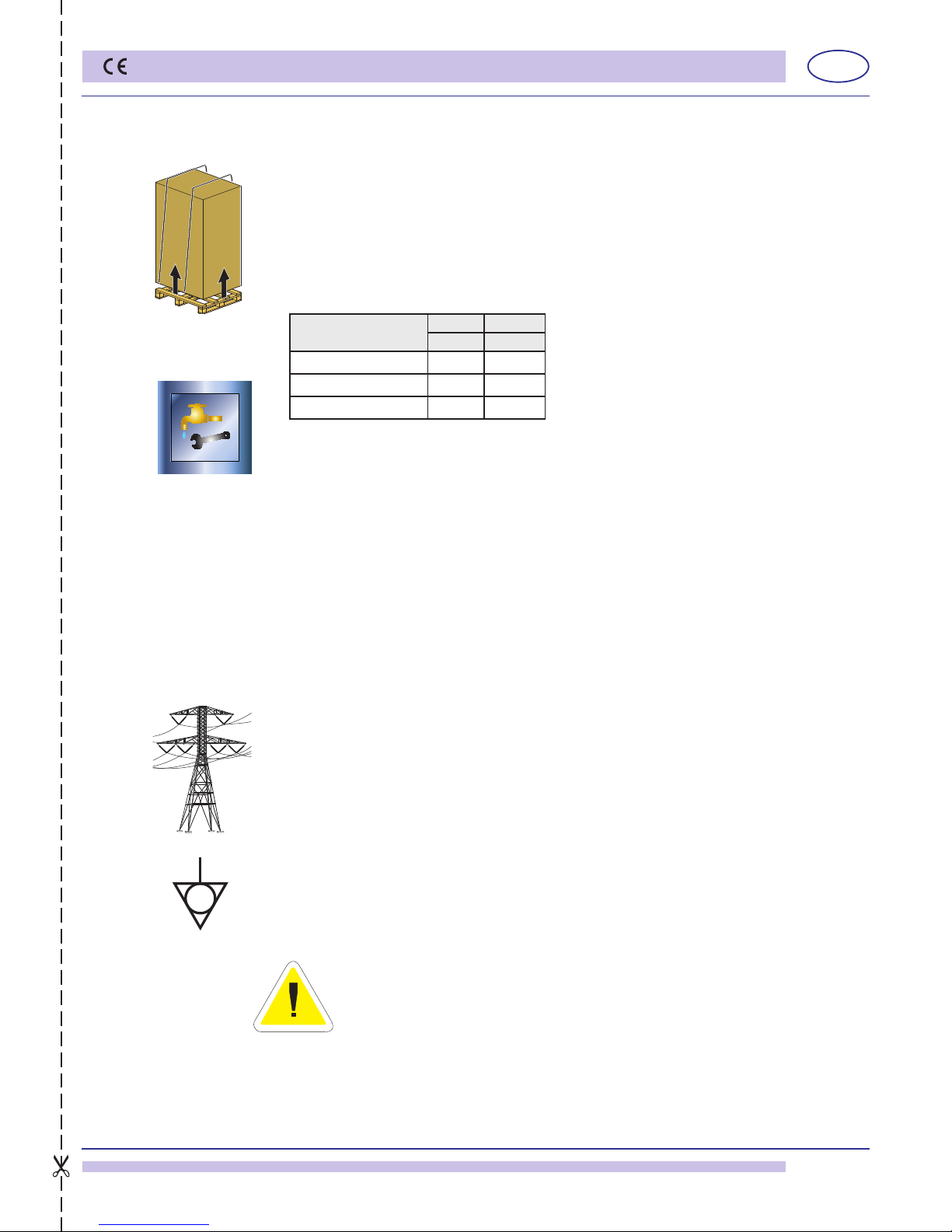
1.1 Receiving product
After removing the packaging, make sure that the apparatus was not damaged during transportation. If this should be the case, notify the seller of the defect. For packaging disposal
see chap. 9.
1.2 Water connection
Connect the machine water supply with a stop valve that can quickly and completely
turn off water ow.
Make sure that the water supply system is within the parameters reported in tab. 1.
If the water system pressure is above 4 BARS (400 KPa), a pressure reducer is recommended.
It is compulsory to install a water-softner for water with average hardness above
10°f.
Dishes/objects will be cleaner and the machine will last longer.
Each machine is supplied with a rubber water load tube with a 3/4"F threaded connection.
It is recommended to connect the tube to water supply systems that do not exceed 55°C,
if connected to hot water.
Connect the supplied machine draining tube to the connector located under the tank, making
sure that the water ows freely (giving, therefore, minimum slope).
The drain tube shall always be connected to a siphon (Ø) in order to prevent the release of
odours. The MAXIMUM drain permitted height is 10cm.
1.3 Electrical connection
The electrical connection shall be carried out in accordance to the laws in force.
Make sure that the line voltage is the same as that written on the machine plate. Apply a
suitable magneto-thermic omni polar switch measured in accordance to absorption
and that is equipped with a contact opening of at least 3 mm (always turn the machine
off with this switch). This is the only switch which guarantees total electric supply
system isolation.
This switch shall be solely and exclusively used for this purpose and installed in the immediate vicinity.
Make sure that the facility is equipped with efcient grounding.
Moreover, the machine has a clamp at the back indicated by the symbol (see g. 1) that is
used for equipotent connection among different apparatuses. The maximum power expresses
in watts (W) and amperes (A) is located on the serial number plate for line measurement,
cable and switches.
N.B.: for machines cable types H05RN-F or H07RN-F must be used or replace with
others which correspond to the regulations of the country where the ware-washer is
installed. A 4mm² section for voltage 380-415V3~, and a 6mm² section for voltage
220-240V3~. The replacement of the cable must be carried out by specialized
personnel only.
The seller/importer/installer must adapt the supply cable isolation class in function to the
work environment respecting the Technical Regulations in force.
pict. 1
Pressure table
Min. Max.
kPa kPa
Static Pressure 250 400
Dynamic Pressure 200 300
Hardness 2°f 10°f
table 1
EN
page 28
INSTALLER SECTION
pict. 3
pict. 2
Attention: some of the machine versions can disperse more than 10mA to earth.
Proceed to machine start-up and rinse aid dispenser calibration as follows:
1) Turn on the wall switch and the water tap.
2) Turn on the ware-washer by pressing key (B) (see par. 2). The relevant green led will
come on.
3) The machine begins to load water in the boiler and the tank (it is important to not open
the door).
4) Once water is loaded, it is heated in the boiler then subsequently in the tank.
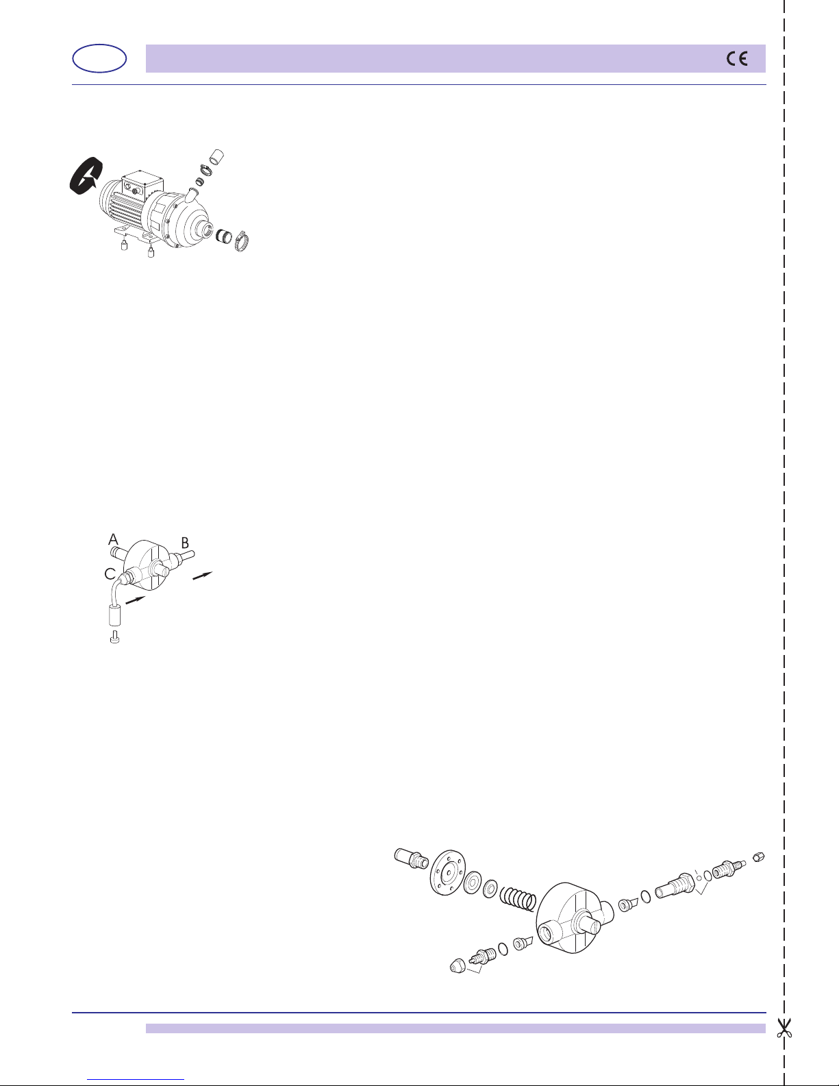
5) It is already possible to verify correct pump rotation pressing the START key, since, being
tri-phase, it can rotate the other way. In addition to the orientation arrows, this is also
indicated by excess noise during the wash cycle (see g. 2).
Important: improper pump rotation can cause impeller unscrewing and rotary seal water
leakage.
6) The machine is ready for washing.
The machine’s sound level is Lp
A = 82dBA ± 2.5. **
**test made according to EN 60335-2-58/A11
1.4 Rinse aid dispenser operation
Dispenser operation g. 3:
Use the rinse pressure pump to withdraw from the canister and inject the rinse aid into the
boiler during the wash phase.
Water connection (for replacement only):
1) Use the rubber tube installed on the machine to hook up the dispenser to its connector
(B) with the special connector located near the boiler (injector).
2) The green tube, on the other hand, which comes out of the suction connector (C), shall
be inserted with a small lter and relevant ballast, in the rinse aid product withdraw
canister (during use).
The connector “A” shall be hooked up to the rinse circuit with a “T” connection.
Initiation:
For initiation simply start the machine and carry out a few wash and rinse cycles.
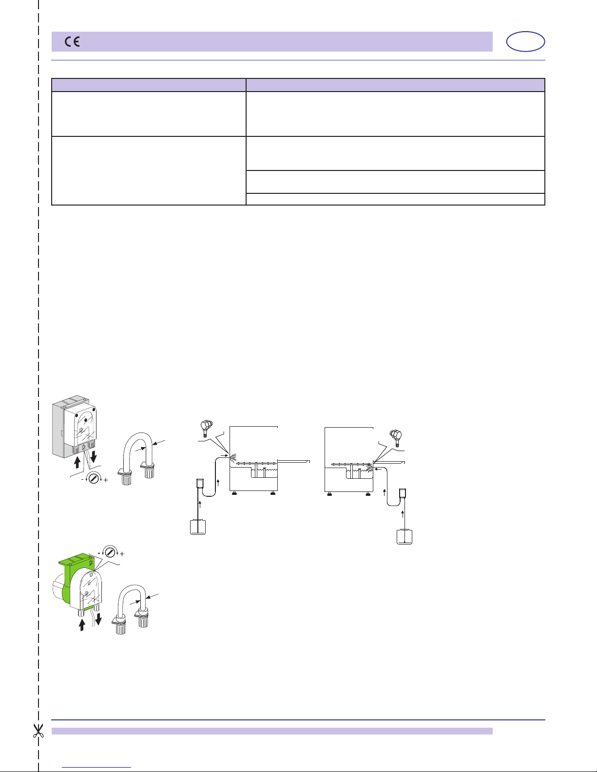
Regulation:
During each cycle the dispenser withdraws an adjustable quantity of rinse aid product from
0 to 4 cm
3
equivalent to the suction length in the tube from 0 to 30 cm.
The minimum ow is obtained by completely screwing the regulation screw (D) (clockwise),
while maximum ow is obtained by unscrewing the regulation screw with about 20 rotations
(counter-clockwise).
For proper chemical product dosage see the product manufacturer notes (see also par.
7.4).
N.B.: for each screw rotation the rinse product dosage varies from 1,6 cm sucked into the
tube, equal to 0,2 cm3/rotation (about 0,21 g/rotation with product density of 1,05 g/cm3).
The rinse aid dispenser cannot function properly is there is a slope of over 40 cm
between the bottom of the machine and the canister.
THE DISPENSERS ARE PRE-CALIBRATED AT A SUCTION OF 5 CM FOLLOWING
OPERATIONAL VERIFICATION AND INSPECTION. THIS PARAMETER SHALL
BE MODIFIED BY RINSE AID TYPE AND WATER HARDNESS.
Cod. 10799/G
12506
10705/O
10705/M
10705/D
10705/D
10705/G
10799/G
pict. 4a
PLUS version
EN
page 29
INSTALLER SECTION
1.5 Detergent dispenser installation
Electrical connection:
Consult the electric diagram enclosed with the dishwasher.
Water connection:
a) Properly assemble the injector (C), using the appropriate washers.
b) Connect the suction straw to the dispenser suction attachment (see g 5 point A).
c) Connect the ow straw to the other dispenser attachment and the ow connector (see
g. 5 point B).
d) insert the straw with lter into the detergent canister.
e) Prime the detergent and proceed with the dosage phase
Dosage:
The detergent dosage ow can be regulated with a screwdriver as indicated in g. 6. Every
2 cm of product sucked into the tube corresponds to 0,25 cm3 equal to 0,3 g (with 1,2 g/
cm3 density). See also par. 7.3.
N.B.: A dispenser with a conductivity probe in the tank is recommended.
pict. 5
GERMAC
15185
Ø 8
SEKO
15108/E
Ø 10
pict. 6
A
B
C
A
B
C
PROBLEM CAUSES AND REMEDY
Water leaks from rins aid suction tube The suction valves 10705/D and ow do not seal due to foreign bodies is
the clamping seats. Clean valves 10705/D, check if the rinse aid suction
lter is present. Make sure there are no crystals or solid pieces inside the
canister which could be due to old, dried-out product.
The dispenser does not suck up rinse aid a) The ow valve 10705/D does not seal due to foreign bodies in the
clamping seats. Clean the valve 10705/D, check if the rinse aid suction
lter is in place.
b) The piston washer does not seal because it is ruined. Replace the
washer with an original.
c) Check that membrane 10705/O is intact.
EN
page 30
INSTALLER SECTION
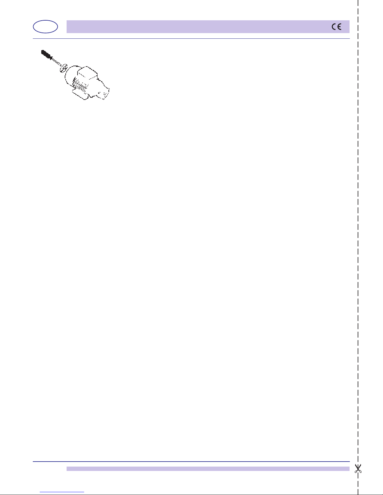
1.6 Increase pressure/rinse pump
After a period of inactivity of the ware-washer, check that the rinse pump rotates freely.
If it is blocked, move the pump shaft, by inserting a screwdriver in the notch, rotating
clockwise and counter-clockwise (see g. 9). This operation may be necessary when
the slow tank-loading alarm sounds (7) (chap. 11.2).
1.7 Emptying boiler and break tank
This function lets the boiler and break tank empty for any extraordinary maintenance or
emptying function.
• Press key “B” (Stand By) and make sure that the tank is empty.
• Simultaneously press keys “E” and “F” (granule cycle selection/water cycle selection)
for about 5 seconds; Boiler and break tank emptying is activated.
The display will show the message “Empty” during the entire emptying cycle.
• Once emptying is complete, the machine can be turned back on with key “B” (ON), but
is frozen until the tension is removed and replaced by the general wall switch.
pict. 9
 Loading...