

KROMA BM5414, BM5420 User Manual

Professional Monitors 14” & 20”
BM5414/BM5420
User Manual
BM5414/20D11
Edición 01
June 2002
KROMA T E L E C O M
Pol. Ind. Alcobendas - C/ La Granja, 80
28108 Madrid - Spain
Tel. (34-91) 661 45 14
Fax. (34-91) 661 58 75
e-mail: sales@kromatelecom.com
www.kromatelecom.com

KROMA TELECOM PROFESSIONAL MONITORS BM5414/20
BM5414/20
1
WARNING:
This product includes critical
mechanical and electrical parts which are
essential for X-Radiation safety.
For continued safety replace critical components
indicated in the service schematic only with exact
replacement parts given in the parts list of
service Manual.
Operating high voltage for this product is 16 Kv.
At minimum brightness. Refer to service manual
for measurement procedures and proper service
adjustments.
WARNING:
Electric shock or fire hazard can be
caused if critical components are replaced by non
conform components. Refer to parts list of service
manual
.
CAUTION:
High vacuum tube is dangerous to
handle refer replacement to qualified personnel.
Replace with a tube of the same type for continued
safety.
SAFETY INFORMATION

KROMA TELECOM PROFESSIONAL MONITORS BM5414/20
BM5414/20
2
INDEX
1. INTRODUCTION .................................................................................................................................1
1.1. A
PLICATIONS ..................................................................................................................................1
1.1.1. FEATURES..............................................................................................................................1
1.1.2. PICTURE TUBE......................................................................................................................1
1.1.3. COLOUR STABILITY..............................................................................................................1
1.1.4. FLEXIBILITY ..........................................................................................................................1
1.1.5. AUTO SETUP SYSTEM ..........................................................................................................2
1.1.6. REMOTE CONTROL .............................................................................................................2
1.1.7. MENU......................................................................................................................................2
1.1.8. NORMAL SIZE, UNDERSCAN AND 16:9..............................................................................2
1.1.9. MEMORIES.............................................................................................................................2
1.2. TECHNICAL
SPECIFICATIONS ..............................................................................................3
1.2.1. SCAN & SYNC.........................................................................................................................3
1.2.2. PICTURE DISPLAY ................................................................................................................3
1.2.3. CRT..........................................................................................................................................3
1.2.4. DECODER PAL / NTSC PERFORMANCE ............................................................................3
1.2.5. LUMINANCE ..........................................................................................................................4
1.2.6. CHROMINANCE.....................................................................................................................4
1.2.7. GENERAL ...............................................................................................................................4
1.3. INSTALLATION ..........................................................................................................................5
1.3.1. Incoming Inspection ................................................................................................................5
1.3.2. Safety Information ...................................................................................................................5
1.3.3. Connection to the Main ...........................................................................................................5
1.3.4. Location...................................................................................................................................6
1.3.5. Tally Lamp...............................................................................................................................6
1.3.6. Ground Terminals ...................................................................................................................7
1.3.7. Remote Control Connectors (RS-485 Interface)......................................................................7
2. INPUTS SELECTION .........................................................................................................................8
2.1. CCVS
KEY.....................................................................................................................................8
2.2. CDV
KEY.......................................................................................................................................8
2.3. CAV
KEY.......................................................................................................................................8
2.4. AUX
KEY.......................................................................................................................................8
3. AUXILIARY FUNCTIONS .................................................................................................................9
3.1. SYNC
KEY.....................................................................................................................................9
3.2. SIZE
KEY ......................................................................................................................................9
3.3. 16:9
KEY ........................................................................................................................................9
3.4. DEL
KEY .......................................................................................................................................9
3.5. BLUE
KEY...................................................................................................................................10
3.6. MONO
KEY.................................................................................................................................10
3.7. AFC
KEY .....................................................................................................................................10
3.8. DEG
KEY.....................................................................................................................................10
3.9. ESC
KEY......................................................................................................................................10
3.10. STS
(STATUS) KEY ......................................................................................................................11
3.11. CHN
KEY.....................................................................................................................................11
3.12. VOL
/ MUTE KEY ......................................................................................................................11
4. COMMAND KEYS FUNCTION.......................................................................................................11
4.1. BLK
KEY (BLACK LEVEL / BRIGHT).........................................................................................11
4.2. CNT
(CONTRAST).....................................................................................................................12
4.3. SATURATION/COLOUR..........................................................................................................12
4.4. HUE/TINT
(ONLY IN NTSC) ......................................................................................................12
4.5. APT
(APERTURE)......................................................................................................................12
4.6. CAL
KEY .....................................................................................................................................12
5. INDICATORS .....................................................................................................................................13

KROMA TELECOM PROFESSIONAL MONITORS BM5414/20
BM5414/20
3
5.1. UNCAL LED................................................................................................................................13
6. MENU OPERATION..........................................................................................................................13
6.1. STATUS
MENU ..........................................................................................................................13
6.2. MEMORY
RECALL MENU......................................................................................................14
6.3. SET
UP MENU ............................................................................................................................14
6.3.1. OPTION: AUTO SET UP......................................................................................................15
6.3.2. OPTION : CRT/REF..............................................................................................................16
6.3.3. OPTION: LEARN PROBE OPTION .....................................................................................16
6.4. OPTION:
MANUAL SET UP....................................................................................................17
6.4.1. OPTION: MENU GRAY SCALES .........................................................................................17
6.4.2. OPTION: MENU CALIBRATION VALUES..........................................................................18
6.5. OPTION:
CHANGE PASSWORD MENU ...............................................................................20
6.6. OPTION:
TECH. MENU............................................................................................................21
6.7. O
PTION: SAFE AREA MENU ....................................................................................................21
6.7.1. Option: DISABLE..................................................................................................................22
6.7.2. Option: TOP MARGIN ..........................................................................................................22
6.7.3. Option: LEFT MARGIN ........................................................................................................23
6.7.4. Option: COLOR ....................................................................................................................23
6.7.5. Option: VIEW S.A..................................................................................................................23
6.7.6. Option: RESET S.A................................................................................................................23
6.7.7. Option: LEFT ........................................................................................................................23
6.7.8. Option: RIGHT......................................................................................................................24
6.7.9. Option: TOP ..........................................................................................................................24
6.7.10. Option: BOTTOM..................................................................................................................24
6.8. MEMORY
STORE MENU.........................................................................................................25
6.9. O
PTION: PROG.FUNCTION......................................................................................................25
6.9.1. Option: SYNC KEY................................................................................................................26
6.9.2. Option: CHN KEY .................................................................................................................26
6.9.3. Option: MUTE SYM ..............................................................................................................27
6.9.4. Option: SYNC ........................................................................................................................27
6.9.5. Option: MODE ......................................................................................................................27
6.9.6. Option: GRID ........................................................................................................................27
6.9.7. Option: GUN OFF SELECTION...........................................................................................27
6.10. O
PTION: EMBEDDED AUDIO...................................................................................................28
6.11. O
PTION: REMOTE MENU .........................................................................................................28
6.11.1. Option: REM ID ....................................................................................................................29
6.11.2. Option: REMOTE MODE .....................................................................................................29
6.12. O
PTION: CONFIG VALUES.......................................................................................................29

KROMA TELECOM PROFESSIONAL MONITORS BM5414/20
BM5414/20
1
1. INTRODUCTION
1.1. Aplications
The KROMA monitors described have been designed to use in Broadcast studios for
signal evaluation requiring accurate picture reproduction. Also it can be used in
production and post-production.
They incorporate microprocessor based control in all its operations, providing
automatic color set-up, thus eliminating the operator´s subjetive factor.
1.1.1. FEATURES
BM5414 /BM5420 14” or 20”
Basic version CCVS: 2 inputs PAL and NTSC
Options:
Decoders:
- Analog Component RGB / YPrPb
- Serial digial video: 2 inputs at 10 Bits resolution according to (ITU-R
BT601).
1.1.2. PICTURE TUBE
High resolution, in line guns an shadow mask tube, with 0.28mm dot pitch for 14”
and 0.4mm for 20”. EBU or P22 phosphor for 14” and EBU or C phosphor for
20”.
1.1.3. COLOUR STABILITY
Beam current feedback,which allows to correct colour temperature drift caused
by CRT variation and environmental conditions.
1.1.4. FLEXIBILITY
Modular configuration. It is provided with an analog and digital bus, allowing the
exchange of signals between the options installed, making it a system of open
architecture for future options.

KROMA TELECOM PROFESSIONAL MONITORS BM5414/20
BM5414/20
2
1.1.5. AUTO SETUP SYSTEM
By use of the KROMA set AK5400X50, composed by a DG5400 test signal
generator and a optical probe model SR5400. The generator is able to provide up
to 34 patterns designed for monitors alignment.
With this combination, automatic grey scale adjustment can by carried out ,as
well as being able to adjust automatically the chrominance signal´s amplitude
and phase.
This set also allows transfering automatically the parameter setting of this setup
to other monitors.
1.1.6. REMOTE CONTROL
The RS-485 bus included in the BM54XX KROMA monitors Is able to control for
up to 128 monitors. These can be in group controlled, individually controlled or all
of them can be controlled at the same time.
1.1.7. MENU
This help the operation, displaying the operating parameters and the commands
to access at several functions.
The adjustmen operations to be done by the specialized personnel are protected
by means of numerical code.
1.1.8. NORMAL SIZE, UNDERSCAN AND 16:9
The monitors are provided with facilities for normal picture size or underscand
(95% reduced size) and aspect ratio 4:3 and 16:9 selectable from the front panel
by size key.
1.1.9. MEMORIES
These monitors have 5 memories:
• All memories accessible through numerical code (only to store datas)
• Four memories for general use.
• One memorie for the system or factory.
KROMA TELECOM PROFESSIONAL MONITORS BM5414/20
BM5414/20
3
1.2. TECHNICAL SPECIFICATIONS
1.2.1. SCAN & SYNC
Systems 625/50/2:1 15.625 Hz
525/60/2:1 15.734 Hz
Horizontal oscilator lock-in range: ± 750 Hz
H sync time constant:
Fast: 0.5 mS
Slow: 2.5 mS
1.2.2. PICTURE DISPLAY
Aspect Ratio: 4:3 and 16:9
- Lineality error: ≤ 2 % of the picture height.
- Geometry error: ≤ 1 % ídem.
- Convergence error:
TUBO ZONE 1 CENTER
14” 0.4 mm 0.15 mm
20” 0.6 mm 0.20 mm
ZONE 1 IS WITHIN A CIRCLE CENTRED ON THE SCREEN WHOSE DIAMETER IS EQUAL TO PICTURE HEIGHT.
1.2.3. CRT
• 14” 0.28 mm pitch Phosphor: EBU and P22
• 20” 0.40 mm pitch Phosphor: EBU and C
• Resolution 14”: > 900 TV lines in the centre
• Resolution 20”: > 900 TV lines in the centre
• Colour Temperature: 6500º K ± 200º K (
IN ALL MEMORIES)
• Black level: Set to 0.5 Nit (
10 % APL WINDOW SIGNAL)
• White level: Set to 90 Nits ( 100% APL WINDOW SIGNAL)
• Beam current limiting: 180 Nit (FLAT FIELD SIGNAL)
1.2.4. DECODER PAL / NTSC PERFORMANCE
• Inputs A, B & C
♦ Level : 1 V
pp
+3/-6 dB
♦ Impedance : 75 Ω ± 1% or loop-through (selectable)
♦ Return Losses: 35 dB @ 5 Mhz.
♦ Isolation between A, B and C inputs: > 60 dB @ 10 Mhz.
♦ Mismatch between A and B: < 1% y < 1º @ 4.43 Mhz
• External sync input

KROMA TELECOM PROFESSIONAL MONITORS BM5414/20
BM5414/20
4
♦ Level : 4 VPP +6 dB / -28 dB
♦ Impedance : 75 Ω ± 1% or loop-through (selectable)
♦ Return Losses: > 35 dB @ 5 Mhz
• Auxiliary signal Input (Front panel)
1
♦ Format : CCVS similar to A and B
♦ Impedance : 75 Ω ± 1%
♦ Return Losses: > 25 dB @ 5 Mhz
1.2.5. LUMINANCE
• Frecuency response:
Without notch filter: 100 Khz - 10 Mhz ± 1 dB
Notch filter suppresion < - 30 dB @ 4.43 Mhz
• K factor
(APERTURE 0 dB) WITHOUT FILTER WITH
FILTER
Kpb < 0.5 % < 1%
K2T < 0.3 % < 1.2%
• Non lineality: < 1%
• Noise : (100 Khz - 5 Mhz) < 60 dB
1.2.6. CHROMINANCE
• Passband : 1.3 Mhz EQUIBAND
• Saturation Control: ± 6 dB
• Subcarrier oscilator lock-in range: 300 Hz
• Luminance-chrominance delay: < 50 nS
1.2.7. GENERAL
• Environmental Characteristics:
♦ Warm-up : 20 minutes to meet specifications.
♦ Temperature range:
From 15 to 40 ºC (TO MEET SPECIFICATIONS)
From 0 to 45 ºC (OPERATING ONLY)
♦ Relative humidity: 0 to 90 % non condensing @ 40 ºC
♦ Altitude : ≤ 3000 m.
♦ X-ray emission: < 0.1 mR/Hr < 0.1 mR/hr @ 5 cm. monitor outside surface
Supply
1
During the auto set-up it controls the channels RGB in parallel.
KROMA TELECOM PROFESSIONAL MONITORS BM5414/20
BM5414/20
5
♦ Voltage : 110 / 220 VAC ± 20%
♦ Power consumption BM5414: 85 W
♦ Power consumption BM5420: 105 W
• Dimensions
Height Width Depth
Model 14” 256 mm. (6 UR.) 417 mm. 470 mm.
Model 20” 444 mm. (10UR.) 449 mm. 482 mm.
• Weight BM5414: 19.2 Kg
• Weight BM5420: 36 Kg
1.3. INSTALLATION
1.3.1. Incoming Inspection
After having removed the equipment from its original packing material, check for
visible signs of damage which may have occurred during shipment. Report any
shortage or damage to the freight carrier and KROMA or its representative
inmediately.
Check that you have received the following accessories with the monitor:
• AC power cord, and
• User´s Manual.
If the equipment has to be reshipped to a long distance, it is recommended to use
the original packing material in order to avoid damages during transport.
1.3.2. Safety Information
For electric shock protection, it is necessary to connect the chassis to a
protective ground; to this purpose, the earth ground terminal of the plug is
directly connected to the metal part of the monitor (green-yellow wire). Insert the
power plug in a mating outlet with an earth ground contact.
Due to the presence of high voltages inside the equipment, the same can only
be open, adjusted or repaired by QUALIFIED PERSONNEL.
1.3.3. Connection to the Main
Before connecting the monitor to the mains, check that the mains voltage
corresponds to that indicated in the voltage selector located in the rear panel,
next to the mains connector.
If the mains voltage presetting is not the appropriate, carry out the change by
removing the fuseholder and turning it until the desired value is shown in the
window.
KROMA TELECOM PROFESSIONAL MONITORS BM5414/20
BM5414/20
6
Fuses should be changed in accordance with the mains voltage presetting
used, as per the following table:
POWER FUSE
220 V 3.15 A Slow
110 V 4 A Slow
1.3.4. Location
Due to the CRT´s sensitivity to magnetic fields, avoid installing the monitor near
this type of disturbance sources such as: Loudspeakers, electric motors,
transformers, etc.
The monitor has a degaussing device incorporated which operates
automatically when the equipment is switched on. It can also be activated
manually from the front panel controls.
If the monitor is changed of location, some colour impurities may occur due to
the variation of the earth magnetic field. This problem disappears by activating
the degaussing circuit with the DEG key.
During the time this operation last avoid placing near the monitor items which
have magnetic information such as: tapes, cassettes, cards, etc.
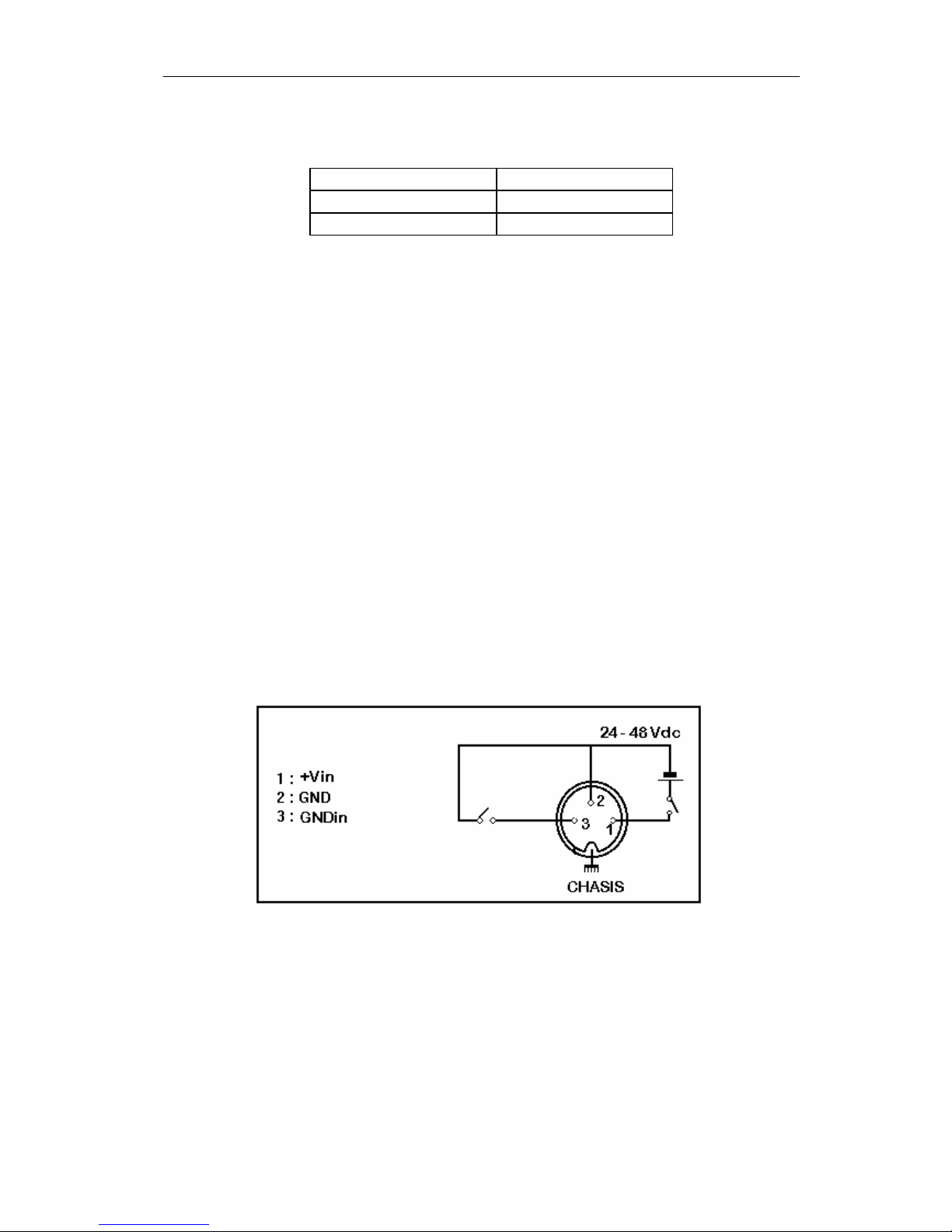
1.3.5. Tally Lamp
This lamp, located on the monitor´s front panel, can be activated with voltages
within the range + 24V - + 48 V. or by closing of the contacts 1 and 3 of the
connector located in the rear panel. (see figure)
 Loading...