


880708
011648
(6-1140-601-20)
W 401L
Universal- Ölheizer Multi-Oilheater Chauffage polycombustible
und Warmluftgebläse and Blower
et ventilation
Betriebs- Instruction Notice
anleitung handbook d’instruction
Stand August 2007
2
Bestell-Nr.
Requisition number
Numéro de commande
bis 2001 ab 2001
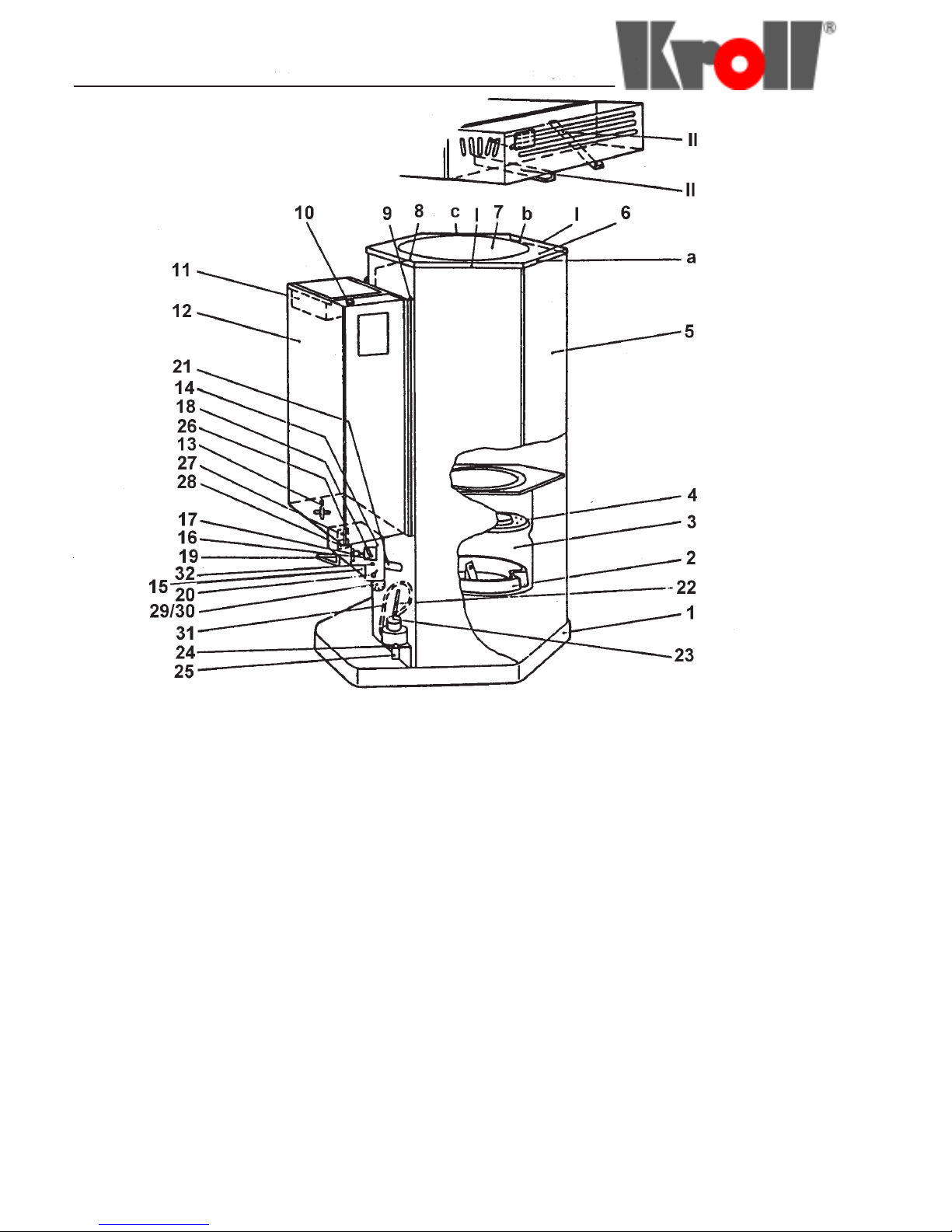
1 Auffangwanne 1 Drip pan 1 Bac-collecteur 5-1140-009-00 001813
2 Brennschale 2 Burner basin 2 Coupelle de combustion 6-1140-015-00 011639
3 Brennertopf 3 Oil chamber 3 Pot de combustion 4-1140-020-00 001455
4 Pilotring 4 Pilot ring 4 Stator d’évoporation 6-1140-522-00 011641
5 Brennkammer 5 Combustion chamber 5 Chambre de combustion 4-1140-030-00 001457
6 Abdeckplatte 6 Cover plate 6 Couronne de couvercle 5-1140-041-00 001823
7 Deckel 7 Lid 7 Couvercle 5-1140-529-00 001856
8 Umlenkklappe 8 Baffle 8 Chicane 5-1140-040-00 001822
9 Blende 9 Housing 9 Ecran thermique 5-1140-043-00 001825
10 Hauptabstellhahn 10 Main stopcock 10 Robinet principal 6-0300-056-00 005290
11 Sieb 11 Strainer 11 Tamis 4-1140-060-00 001460
12 Tank 12 Tank 12 Réservoir 3-1140-050-10 000950
13 Wasserablaßhahn 13 Water drainage cock 13 Robinet de purge 6-0300-001-00 005251
14 Motorkonsole 14 Motor mount 14 Support de moteur 2-1140-065-00 000717
15 Motordeckel 15 Motor cover 15 Couvercle de moteur 5-1140-072-00 001833
16 Motor 16 Motor 16 Moteur 6-0300-132-00 005351
17 Zahnradpumpe 17 Gear pump 17 Pompe à engenages 6-0300-341-00 005513
18 Abstellhahn-Oberteil
Abstellhahn-Unterteil
18 Stopcock bass upper part
Stopcock bass lower part
18 Robinet socle partie supérieure
Robinet socle patie inférieure
6-1140-557-00 011645
011644
19 Ölleitungs-Rohrbogen 19 Oil feed line 19 Tuyau de liaison 3-1140-133-00 000954
20 Wippschalter 20 Rocker switch 20 Commutateur 6-0400-148-00 006529
21 Einlaufrohr 21 Oil inlet 21 Canne d’alimentation 2-1140-129-00 000720
22 Überlaufrohr 22 Overflow pipe 22 Tuyau de trop-plein 5-1140-112-00 001835
23 Alu-Becher 24 Aluminium catchment 23 Godet en alu 6-0300-003-00 005252
24 Mikroschalterhalter 24 Microswitch holder 24 Support de microrupteur 6-0400-175-00 006556
25 Mikroschalter 25 Microswitch 25 Microrupteur 6-0400-098-00 006484
26 Steckdose 26 Socket 26 Prise de courant 6-0400-005-00 006404
27 Netzanschluß mit Stecker 27 Power cord with plug 27 Câble d’alimentation avec prise 6-0400-060-00 006450
28 Netzanschluß 28 Cable with plug 28 Câble avec prise 6-0400-057-00 006448
29 Verbrennungsluftgebläse 29 Combustion air fan 29 Soufflerie de combustion 5-1140-114-00 001837
30 Gebläseisolierung 30 Fan insulating 30 Isolement de soufflerie 6-1140-614-00 011649
31 Thermostat 31 Thermostat 31 Thermostat 6-0300-243-00 005439
32 Mutter 32 Nut 32 Ecrou 6-0200-261-00 003504
33 Festspannscheibe 33 T ightening disk 33 Rondelle de serrage 4-1140-023-00 001456
34 Dichtung 34 Special sial 34 Joint spécial 6-0300-178-00 005386
35 O-Ring 35 Seal 35 Joint 6-0200-075-00 003370
36 Übergangsstück oben 36 Upper adaption portion 36 Rac cord supérior 6-1140-572-00 011646
37 Fiberdichtung 37 Fiber seal 37 Joint en fibre 6-0200-037-00 003339
38 Übergangsstück unter 38 Low er adaption portion 38 R accord inférieur 6-1140-573-00 011647
39 Kupplungsstück mit Schlitz 39 Clutch disk slit 39 Disque d’accouplement avec fente 6-0301-673-00 006339
40 Kupplungsstück mit Stift 40 Clutch disk with peg 40 Disque d’accouplement avec
goupille
6-0301-674-00 011647

3
Bestimmungsgemäße
Verwendung
- KFZ- Werkstätten
- Tankstellen
- Bauwagen
Designated use
- Atelier de réparations d’automobiles
- Station-service
- Wagon de chantier
Désignation
- Automobile workshop
- Filling station
- Construction wagon
Einleitung
Sie haben sich einen Kroll-Universalöl-Heizer
zugelegt, der Ihnen einwandfreie Funktion,
Sicherheit und einen störungsfreien Einsatz
garantiert, wenn Sie die Aufstellung, Inbetriebnahme und Reinigung nach folgenden
Angaben ausführen werden.
Für die Aufstellung gelten die allgemeinen
Vorschriften für Ölheizer der jeweiligen
obersten Baubehörde für Ihr Land. Der Ofen
darf keinesfalls in der Nähe brennbarer
Flüssigkeiten betrieben werden.
Aufstellung
Folgende Teile sind aus dem Heizer zu
nehmen:
Brennschale (2), Pilotring (4), Umlenkklappe
(8), Tank (12)
Im Tank befinden sich Ölleitungsrohrbogen
(19), Fiberdichtung für Anschluß zwischen
Übergangsstück (Abb.5/38) und
Ölleitungsrohrbogen oben und das Sieb (11).
Stellen Sie den Heizer in die Ölauffangwanne
(1). Brennschale (2) mittels des mitgelieferten
Hakens auf den Boden des Brenntopes
stellen und die Aussparung gegenüber des
Einlaufrohres (21) verdrehen. Piloring (4) mit
Wölbung nach oben auf den eingeprägten
Rand des Brennertopfes legen. Umlenkklappe (8) in den Winkel über dem Rohrstutzen einhängen. Den Tank (12) in die Schlitze
der Blende (9) einhängen.
Ölleitungsrohrbogen (19) unten mit Einlaufrohr (21) und oben am Tank mit Dichtung
verschrauben. Beim Fest-schrauben muß das
Übergangsstück an der Pumpe (Abb. 5/36)
gegengehalten werden, da sonst die Flucht
der Pumpenachse verändert werden kann.
Die Dichtung ist an dieser Betriebsanleitung
angeheftet.
Den 5-poligen Stecker (28) von links in die
Steckbuchse der Motorkonsole (14) einstecken. Jetzt prüfen Sie, ob der
Wasserablaßhahn (13) geschlossen und der
Alu-Becher (23) lose im Microschalterhalter
stehen. Der Microschalterhebel soll den aluBecher nach oben drücken.
Introduction
Your new Kroll-Multi-oilheater is guaranteed
to function properly, safely and continously if
you install, operate and clean it in compliance
with the following instructions.
Your installation should comply with oilheater
installation regulations as issued by your local
and national building authorities. The stove
should never be operated near inflammable
liquids.
Installation
Remove following parts from the heater:
burner basin (2), pilot ring (4), baffle (8), tank
(12)
In the tank you will find the oil feed line (19),
the fibre seal for the connection between the
adapter (Abb.5/38) and upper oil feed line, as
well as the filter (11).
Place the heater on the drip pan (1). Place
the burner basin (2) at the bottom of the oil
chamber using the hook supplied for this
purpose and rotate the basin so that the
recess is in the opposite of the inlet pipe (21)
Lay pilot ring (4) on the patterned rim of the
oil chamber. Insert baffle (8) onto bracket
above the flue connection. Hang the tank (12)
into the slits in the housing (9). Fasten lower
end of feed line (19) to inlet line (21) and the
upper end to the tank using the seal. When
screwing on, counterhold reducer on pump
(Abb. 5/36) since otherwise alignment of
pump axis may be changed. The seal in a
plastic bag is affixed at the manual.
Insert a 15-terminal plug (28) into the socket
at the left of the motor mount (14).
Now make sure the water drainage cock (13)
is closed and the aluminium catchment (23) is
sitting loosely in the micro-switch holder. The
micro-switch lever should press the
aluminium cup upwards.
Introduction
Vous venez de faire l’achat d’un poêle Kroll
pour chauffeur poly combustible. Le
fonctionnement impeccable de ce poêle, sa
sécurité et un service sans incidents vous
sont garanties si vous procédez à
l’installation, à la mise en service et au
nettoyage en respectant les indications
suivantes.
Installation
Sortir du chauffeur les pièces suivantes:
la coupelle de combustion (2), le stator
d’évaporation (4), la chicane (8), le réservoir
(12)
Dans le réservoir se trouvant le tuyau de
liaison (19), un joint en fibre pour le
branchement entre le raccord (Abb.5/38) et le
tuyau de liaison supérieur ainsi que le tamis
(11).
Poser le chauffeur dans le bac-collecteur (1).
Avec le crochet fourni, poser la coupelle de
combustion (2) sur le fond du pot de
combustion et amener la découpe en face de
la canne d’alimentation (21). Poser le stator
d’évaporation (4) sur le bord profilé du pot de
combustion. Accrocher la chicane (8) dans
l’angle au-dessus du tuyau. Accrocher le
réservoir (12) dans les fentes de l’écran
thermique (9). Visser le tuyau de liasion (19)
en bas sur la canne d’alimentation (21) et en
haut sur le réservoir, avec un joint
d’étanchéité. Au serrage, il faut retenir le
raccord réducteur monté sur la pompe
(Abb. 5/36) sinon l’aglimnement de l’axe de la
pompe risque d’être modifié. Ce joint est
agrafé à la presente notice.
Brancher la fiche à 5broches (28) dans la
prise du support du moteur (14), du côté
gauche. Vérifier alors si le robinet du purge
(13) est fermé et si le godet en alu (23) est
posé librement dans le support du
microrupteur. Le levier du microrupteur doit
repousser le godet en alu. le levier du
microrupteur doit repousser le godet an alu
vers le haut.

4
Abgasrohrführung
Der Heizer muß an einen Schornstein oder
Hilfsabzug angeschlossen werwerden,
dessen Mündung das Dach mind. um 1m
bzw. den Gebäudefirst mind. um 0,5m
überragt.
Abgasschornsteine müssen im freien
Windstrom liegen. Die Mündung des Abgasrohres darf nicht in unmittelbarer Nähe von
Fenstern und Balkonen liegen.
Beim Verlegen der Abgasrohre ist auf
fortwährende Steigung (Abb.“a“) und richtiges
zusammenstecken in Zugrichtung zu achten.
Der Rohrdurchmesser (Abb.“b“) muß wegen
guter Zugführung größer als der Stutzendurchmesser sein. Waagerecht verlegte
Abgasrohre (Abb. „c“) dürfen nicht länger als
1/3 der gesamten Abgasrohrlänge betragen.
Am Fuße des Rauchgasabzuges sammeln
sich Kondens- und Regenwasser. Deshalb
muß möglichst weit unten (Abb. „d“) am
Abgasrohr ein Kapselwinkel eingebaut
werden.
Für eine saubere Verbrennung ist genügend Zug erforderlich.
Bei W 401L 2,5 - 4 mm WS. Die wirksame
Schornsteinhöhe muß mind. 4m betragen.
Stovepipe
The heater must be connected to a chimney
or other flue pipe whose head is at least 0,5m
above the roof ridge or else 1m above other
roof locations.
Flue outlets must stand in direct wind
currents. The flue head may not be located in
the immediate vincinity of windows or
balconies.
In laying the flue pipes it is important to
maintain upward slope (example “a“) and
insert pipe sections properly in the direction of
exhaust.
The pipe diameter (example “b“) must be
larger than the diameter of the stove
connection to ensure proper drawing.
Horizontal pipe sections (example “c“) may
not be longer than one third of the total flue
length.
Rain and condensation water collect at the
bottom of the flue. It is therefore important to
install a cap elbow as low as possible
(example “d“) in the flue pipe.
The flue must draw properly to ensure
adequate, smokeless combustion.
This is 2,5 - 4 mm ws for the W 401L . The
flue height must be at least 4m to be
effective.
Le cheminée
Le chauffer doit ête raccordé à une cheminée
ou à conduite de fumée auxillaire débouchant
au moins à 1m au-dessus du toit ou au moins à
0,5m au-dessus du faite du bâtiment.
La cheminée doit se trouver dans une zone de
libre circulation vent. Elle ne doit pas
déboucher à proximité immédiate de fenêtres
et de balcons.
Lors de l’installation des tuyaux de poêle, is
faut veiller à ce que ceux-ci soient toujours
dirigés vers le haut (fig. „a“) et correctement
emboîtés dans le sens du tirage.
Pour garantir un bon tirage, il faut que le
diamètre du tuyau (fig. „b“) soit supérieur au
diamètre du raccord. La Longueur de tuyaux de
poêle posés à l’horizontale (fig. „c“) ne doit
dépasser 1/3 de la longueur totale des tuyaux
de poêle.
Au point le plus bas de la cheminée
s’accumulen l’eau de pluie et la condesation.
C’est pouquoi il faut monter un te tampon sur le
tuyau de poêle, le plus bas possible (fig. „d“)
Pour une combustion propre, un bon tirage
est néccessaire.
C’est-à-dire: 2,45 - 4 mm pour W401L. La
hauteur utile de la cheminée doit atteindre au
moins 4mm.
Abb. 2 / Example 2 / Fig. 2
Abb. 3 / Example 3 / Fig. 3
B1 Thermostat B1 Thermostat B1 Thermostat
B2 Mikroschalter B2 Micro switch B2 Microrupteur
H1 Signallampe H1 Operating lamp H1 Lampe d’utilisation
M1 Verbrennungsluftgebläse M1 Combustion air fan M1 Soufflerie d’air de combustion
M2 Getriebemotor M2 Motor M2 Moteur
S1 EIN/AUS Schalter S1 ON/OFF switch S1 Interrupteur MARCHE/ARRET
X1 Motorkonso le X1 Motor brac ket X 1 Bloc co mp l et moteu r
X2 Überlaufsicherung X2 Overflow security X2 Sécurité de débordement
X3 Verbrennungsluftgebläse X3 Combustion air fan X3 Soufflerie d’air de combustion

5
Inbetriebnahme und
Bedienung
Netzstecker (230V) einstecken, Wippschalter
(20) auf „ein“, Regulierhebel (18) auf „schwach“
stellen (notfalls an Kupplungsscheibe drehen,
bis Zahnrad frei wird) und den Hauptabstellhahn (10 aufdrehen. Heizöl über Sieb (11) in
den Tank einfüllen. Nun gießen Sie beim W401
L 1/4Liter Heizöl in die Brennschale (2) und
entzünden es mit einem Wachsdocht oder in
heizöl getränkter Putzwolle. Ofendeckel
auflegen. Heizer nur in kaltem Zustand zünden.
Achtung: Nicht mehr als 1/4 Liter bzw. 1/8
Liter Heizöl wegen Überhitzungsgefahr.
Wenn der Heizer die nötige Betriebswärme
erreicht hat (je nach Raumtemperatur 10 - 15
Min.) schaltet der Thermostat (31) den
Getriebemotor (16) mit Zahradpumpe (17) ein
Signallampe(32).
Lassen Sie den Heizer die ersten 20 MIn. auf
„schwach“ laufen. Wenn erforderlich, können
Sie danach den Regulierhebel (18) auf „stark“
stellen.
Bei Verwendung von Heizöl EL nur auf Stellung
„schwach“ betreiben. Nachregulieren mittels
Hauptabstellhahn (10).
Abstellen
Den Wippschalter auf „aus“ und den Hauptabstellhahn zudrehen.
Reinigung (siehe Abb. 1 und 4)
Schlackenrückstände sind bei der Altölverbrennung unvermeidlich. Zur Reinigung
dient unsere bewährte Brennschale (2). MIt
dem mitgelieferten Haken nehmen Sie zuerst
den Pilotring heraus, dann drehen Sie die
Brennschale mit der Aussparung zum Einlaufrohr und nehmen Sie waagrecht nach oben
heraus. Das Gerät muß täglich gereinigt
werden. Dadurch wird eine leichte Schlackenentfernung gewährleistet, welche nur wenige
Minuten in Anspruch nimmt. Die Schlacke darf
keinesfalls über den Rand der Brennschale
kommen. Sehr vorteilhaft ist die Anschaffung
einer zweiten Brennschale zum Auswechseln
und das Einsprühen der Brennschale und des
Brennertopfes mit Kroll-Schlackenlöser.
Störung
Wenn der Heizer einmal unbeachtet durch
irgendwelche Umstände ausgeht, schaltet das
Thermostat bei absinkender Temperatur die
Pumpe ab. Sollte bei Verwendung von schlecht
brennbarem Öl oder durch zuviel Schlacke in
der Brennschale der Ölspiegel im Brennertopf
zu hoch steigen, so läuft das Öl durch das
Überlaufrohr (22) in den Alu-Becher (23).
Dieser schaltet durch das zunehmende
Gewicht über den Mikroschalter den Pumpenmotor ab. Sollte sich mehr als 1/4 Liter Öl in
der Brennschale befinden, muß dieses vor
erneutem Anzünden entfernt werden. Zuvor die
Ursache beheben und den Alu-Becher
entleeren.
Proper Operating
Procedure
Plug in the stove (230V), throw switch (20) to
“on“, set lever (18) on “low“ (the clutch disk
may have to be turned to free the gear) and
open main stopcock (10). Pour waste oil
through filter (11) into the tank. Now pour 1/2
pint heating oil in the case of W 401 L. Fire it
up with wick. Place lid on heater. Ignite stove
only when it is cold.
Important: There is a danger of overheating if
more than 1/2 or 1/4 pint of heating oil is used !
When the heater has reached the necessary
operating temperature (10 - 15 minutes
depending on the surrounding temperature),
the thermostat (31) switches on the motor (16)
that drives the pump (17) and the indicator light
(32) goes on. Leave the heater on “low“ for the
first 20 minutes. The adjustment lever (18) can
be moved to “high“ after this time if desired.
The adjustment lever should be kept in the
“low“ setting when using EL heating oil. The
main stopcock can be used to adjust the flow.
Turning the stove off
Put switch in “off“ position and close the main
cock.
Cleaning (see diagrams 1 and 4)
Burning waste oil unavoidably leads to slag
residues. Our burner basin (2) has proved very
effective for cleaning operations. First remove
the pilot ring using the hook accessory, then
rotate the burner basin recess around to the
inlet pipe and lift the basin out while keeping it
horizontal. The stove must be cleaned daily.
The quantity of slag residue to be removed is
then small and the operation takes only a few
minutes. The residue should never be allowed
to spill over the rim of the basin. A good system
is to keep a second basin with which to replace
the dirty on every second day and to spray Kroll
Slag Solvent onto the basin and into the oil
chamber.
Periodically inspect the oil inlet pipe, as this
may block up with carbon. Run a 13mm drill bit
through it, to remove any carbon present.
Malfunctioning
If the heater should go out unnoticed for any
reason, the thermostat switches off the pump
when the temperature has fallen to a certain
level. If too much oil collects in the oil chamber
because it is burning poorly or there is too
much slag in the basin, the excess oil will run
through the overflow pipe (22) into the
catchment (23). A certain weight of overflow oil
causes the microswitch to shut off the pump
motor. If more than 1/2 pint of oil is in the basin
it must be removed before reigniting the stove.
Determine the cause of malfunctioning and
empty the catchment before reigniting.
Mise en service et
utilisation
Brancher la fiche sur le secteur (230V), mettre
l’interrupteur (20) sur „ein“ (marche), ajuster le
levier de régulation (18) sur „schwach“ (faible)
(si besoi, faire tourner le disque d’accouplement
jusqu’à ce que l’engrenage soit libre) et ouvrir le
robinet principal (10). Verser le l’huile dans le
réservoir à travers le tamis (11). Verser ensuite
1/4 de litre de mazout pour W 401 L dans la
coupelle de combustion (2) et allumer le feu
avec une mèche de cire ou avec la bourre de
laine imbibée de mazout. Poser le couvercle du
poêle. Alumer le chaufeur uniquement à froid!
Attention: Ne pas verser plus de 1/4 de litre de
mazout a cause des risques de surchauffe !
Une fois que le chauffer a atteint la température
de service nécessaire (au bout de 10 à 15
minutes, suivantes la temperature ambiante), le
thermostat (31) met en marche la moteurréducteur (16) avec pompe à engrenages (17)
et la lampe témoin (32) s’allume. Laisser le
chauffer fonctionner sut feu „faible“ pendant les
20 premières minutes. Si nécessaire, il est
ensuite possible d’amener le levier de régulation
(18) sur „stark“ (fort). En cas d’utilisation de
mazout EL, faire fonctionner le poêle de mazout
EL, faire fonctionner le poêle seulement en
position „schwach“ (faible. Procéder à la
régulation avec le robinet principal.
Arrêt
Mettre l’interrupteur en position „aus“ (arrêt) et
fermer le robinet principal
Nettoyage (voir fig. 1 et 4)
Lors de la combustion d’huiles de récupération,
des socories et autres résidus de combustion
sont inévitables. Notre coupelle dombustion (2)
représente une solution éprouvée pour le
nettoyage. Avec le crochet fourni, sortir tout
d’abord le stator d’evaporation plus faire tourner
la coupelle de combustion pour amener la
découpe du côté de la canne d’alimentation plus
la sortir par le haut, à l’horizontale. L’appareil
doit être nettoyé quodiennement. Dans ce cas,
les scories s’enlévent facilement en quelques
minutes.Les scories s’enlèvent facilement en
quelques minutes. Les scories ne doivent
jamais dépasser le bord de la coupelle de
combustion. Il est avantageux de faire
l’acquisition d’une deuxième coupelle de
remplacement et de pulvérser le Décap-cendres
Kroll sur la coupelle de combustion et sur le pot
de combustion.
Incidents
Se le chauffer s’éteint pour une raison
quelconque, sans qu’on s’en apercoive, le
thermostat arrête la pompe lorsque la
température tombe. Si l’on utilise de l’huile
brûlant mal ou que la coupelle de combustion
contient trop de scories et que le niveau d’huile
monte excessivement dans le pot de
combustion, l’huile parvient dans le godet en alu
(23) à travers le tuyau de trop-plein (22). Sous
l’effet de l’augmentation du poids du godet, le
microrrupteur arête le moteur de la pompe. Si la
coupelle de combustion renferme plus de 1/4 de
litre d’huile, il faut vider la quantité excédentaire
avant de rallumer le feu. Eliminer préalablement
l’origine de cette perturbation et vider le godet
en alu.

6
Wartungsintervalle / Maintenance table / Tableau d’entreteien
Intervalle / period / Fréquence
täglich
daily
jounalière
wöchentlich
weekly
Hebdomadaire
Monatlich
Monthly
mensuel
Jährlich
annually
annuel
Reinigen Sie die Brennschale
Clean the burner basin
Nettoyez le coupelle de combustion
X
Lassen Sie das Kondenswasser des Kraftstofftanks ab
Drain (water of) condensat ion from the fu el tank, w hen
the waste oil contains water
Purgez la condensatio (eau) du reservoir de
combustible si déchét d’huil e cont inent de l’eau
X
Reinigen Sie Brennkammer und Pilotring mit einer
Stahlbürste.
Clean the combustion chamber and the pilot ring with a
steel brush.
Nettoyez la chambre de comb usti on et le stator
d’évoporation avec une brosse à dents.
X
Reinigen Sie das Überlaufrohr im Boden der
Brennkammer.
Clean the oil overflow pipe in the floor of the
combustion chamber.
Nettoyez le tuyau de trop plein d’hu ile au fond de la
chambre de combustion
X
Reinigen Sie die Kraftstoffleitung.
Ersetzen Sie bei Brandschäden oder and eren
Beanstandungen die Kraftstoffleitung.
Clean the oil supply pipe. Replace t he oil supply pipe
when this is burnt out or damaged.
Nettoyez le tuyau d’alimentation en huile.
Remplacez le tuyau d’alimentation en huile s’il est brûle
ou endommage.
X
Überprüfen Sie die Kraftstoffzufuhrleitung auf undichte
Stellen.
Check the oil pipes for leakag e
Vérifiez si les tuyaux d’huil e présent une fuite.
X
Reinigen Sie Tank und Tankfilter. Der Tank kann leicht
abgenommen werden.
Clean the fuel tank and the tank filter. The fuel tank can
easily be removed.
Nettoyez le réservoir de combustible et le filtre à
réservoir à combustible.
Le réservoir à combustible est facilement amovible.
X
Überprüfen Sie den Warmluftventilat or und r einigen Sie
ihn.
Check the hot air fan and clean if necessary.
Contrôlez le ventilateur d’air c haud et net toy ez- le au
besoin
X
Reinigen Sie das Schornsteinverbindungsrohr.
Clean the chimney connecti ng pipe .
Nettoyez la vanne de tuyau de cheminée.
X
Überprüfen Sie die Anschlüsse des Heizers.
Check the heaters wirin g
Vérfier le câblage du générateur
X

7
Heizer nur im kalten
Zustand zünden !
Sollte sich nach monatelangem Betrieb in
Tank, Pumpe oder Leitungen Ölschlamm
abgesetzt haben, so nehmen Sie zur Reinigung
den Tank ab. Hierzu Netzstecker, sowie den 5poligen Stecker (28) ausstecken und
Ölleitungsrohrbogen und das Übergangsstück
abschrauben und die Schlacke ausbohren.
Hierzu empfehlen wir die im Prospekt beschriebenen Reinigungsbürster. Bei zu starker
Verschmutzung des Brennertopfes (3) können
Sie diesen nach oben herausnehmen. Hierzu
sind Einlaufrohr und die 3 Befestigungsschrauben auf der Zwischenplatte auszuschrauben.
Beim Wiedereinbau ist auf diechtes Aufliegen
des Brennertopfrandes auf der Zwischenplatte,
festen Sitz des Einlaufrohres (bei Einlage der
Spezialdichtung) sowie Auslaufrichtung des
Überlaufrohres zum alu-Becher zu achten.
Sollte einmal zuviel Wasser im Tank sein, was
sich durch ungleichmäßiges Brennen und
starkes Zischen der Flamme bemerkbar macht,
muß es durch den Wasserablaßhahn (13)
abgelassen werden. Wenn Öl verschüttet wird,
ist die Auffangwanne unbedingt sofort zu
reinigen, sonst besteht Brandgefahr.
Warmluftgebläse V 470 (Abb.1)
Mit diesem laufruhigen und leistungsstarken
Gebläse wird eine noch schnellere Aufheizung
des Raumes erreicht.
Das Gebläse wird dann mit der Ausblasseite in
Richtung a, b oder c aufgesetzt und mit den
zwei Schrauben (I) durch die Bohrungen (II) an
der Abdeckplatte des Ofens verschraubt.
Gebläsestecker (27) in der Steckdose (26) in
der Motorkonsole anschließen.
Das Netzkabel darf nicht am Heizer anliegen.
Beim W 401L kann das Gebläse nach den
Seiten a, b oder c aufgestzt werden.
Wenn der Heizer ohne Gebläse betrieben wird,
ist der Gebläsedeckel unbedingt zu öffnen !
Achtung !
Bei Betrieb mit Gebläse V 470 weder Stecker
vom Gebläse noch Netzstecker ziehen, bevor
das Gerät vollständig abgekühlt ist.
Ignite Heater only
when it is Cold !
If after several months of operation oil sludge
has collected in the tank, pump or in lines
remove the tank for cleaning. First disconnect
the wall plug and the 5-terminal plug (28) and
disconnect the oil feed line from the tank. If the
inlet pipe is clogged, disconnect the feed line
an the adapter and ream out the sludge. We
suggest using a cleaning brush as described in
the prospectus.
If the oil chamber (3) has become too dirty it
can be removed vertically. To do this, first
remove vertically. To do this first remove the
inlet pipe and the three screws on the middle
section.
When reinserting the chamber make sure that
the rim is resting tightly against the middle
section. The intake pipe (with special seal)
must be firmly mounted and the overflow pipe
must be properly located over the catchment.
Uneven burning and a loud hissing sound are a
sign that there is probably too much water in
the tank. It should be drained off through a
cock (13).
The drip pan must be cleaned immediately if
oil is spilled, otherwise there is a fire hazard.
V 470 blower (example 1)
This quiet-running, high-performance fan unit
helps to heat up the room even faster.
The unit is then mounted with the lower side in
direction a, b or c and then fastened to the
cover plate of the stove with two screws (I)
through the holes provided (II). Insert fan plug
(27) into the socket (26) in the motor mount.
The electric cord should not lie against the
heater.
The fan unit can be mountet on the W 401 L on
the a, b or c side.
While running the heater without the fan, the
fan cover must always be kept on !
Attention !
When operating with the V 470 fan, do not
disconnect the power supply, to the heater, until
the appliance has entirely cooled down !
Allumer le chauffer
uniquement à froid !
Si, après plusiers mois de service, des boues
d’huile se sont déposés dans le réservoir, la
pompe ou les conduites, démonter le réservoir
pour le nettoyer. A cet effet, débrancher la fiche
du secteur ainsi que la fiche à 5 broches (28)
et dévisser le tuyau de liaison du réservoir. Si
la canne d’alimentation est obstruée, dévisser
le tuyau de liaison et le raccord puis éliminer
les scories à la perceuse. Pour cela, nous
recommandons l’utilisation de la brosse de
nettoyage décrite dans le prospectus.
Si le pot de combustion (3) est trop fortement
encrassé on peut le sortir par le haut. Pour
cela, dévisser la canne d’alimentation et les
trois vis de fixation de la plque de séparation.
A la repose, veiller à ce que bord du pot de
combustion porte sur la plaque de séparation
en assurant l’étanchéit´requise. S’assurer que
le canne d’alimentation soit bien fixée
(montage du joint spécial) et que le tuyau de
trop-plein débouche dans le godet en alu.
Si le réservoir contient trop d’eau, ce qui se
manifeste par une combustion irrégulière et un
fort crépitement de la flamme, il faut évacuer
l’eau avec le robinet de purge (13).
Nettoyer touyours immédiatement le baccollecteur si de l’huile a èt`renversée, à cause
des risques d’incendie.
Ventilateur (Fig. 1)
Ce ventilateur puissant au fonctionnement
silencieux permet un réchauffement encore
plus rapide des locaux.
Poser ensuite le boîtier en orientant le
ventilateur das le sens a, b ou c puis le fixer
par deux vis (I) à travers les trous (II) prévus
sur la couronne de couvercle. Brancher la fiche
du ventilateur (27) dans la prise de courant (26)
du support du moteur.
Le câble de racordement éléctrique ne doit pas
toucher le chauffer.
Sur l’appareil W 401 L, le ventilateur peut être
orienté vers les côtés a, b ou c.
Si le poêle est utilisé sans ventilateur, il faut
obligatoirement ouvrir le capot du
ventilateur !
Tout droit à la garantie est exclu pour des
avaries dues à une surchauffe !
Attention !
En ca fonctionnement avec ventilation V 470
tirez ni la prise d’alimentation avant que
l’appareil ne soit pas complétement
refroid !

8
Schema Einlaufrohr mit
Überlaufsicherung
Feed Line with Overflow
Monitoring System
Chéma: Canne d’alimentation
avec système de sécurité de tropplein
1 Auffangwanne 1 Drip pan 1 Bac-collecteur
2 Brennschale 2 Burner basin 2 Coupelle de combustion
3 Brennertopf 3 Oil chamber 3 Pot de combustion
4 Pilotring 4 Pilot ring 4 Stator d’évoporation
5 Brennkammer 5 Combustion chamber 5 Chambre de combustion
19 Ölzuleitungsrohrbogen 19 Feed line 19 Tuyau de liaison
21 Einlaufrohr 21 Inlet line 21 Canne d’alimentation
22 Überlaufrohr 22 Overflow pipe 22 Tuyau de trop plein
23 Alu-Becher 23 Aluminium catchment 23 Godet en alu
24 Mikroschalterhalter 24 Microswitch holder 24 Support de microrupteur
25 Mikroschalter 25 Microswitch 25 Microrupteur
29 Verbrennungsluftgebläse 29 Combustion air fan 29 Souf flerie d’air de combustion
30 Gebläseisolierung 30 Fan insulating 30 Isolement de soufflerie
31 Thermostat 31 Thermostat 31 Thermostat
32 Sechskantmutter M6 32 Hex nut M6 32 Ecrou hexagonal M6
33 Festspannscheibe 33 Tightening disk 33 Rondelle de serrage
34 Spezial-Dichtung 34 Special seal 34 Joint spècial
Motor mit Zahnradpumpe Motor with Gear pump Schéma: Moteur avec pompe à
engrenages
10 Hauptabstellhahn 10 Main stock 10 Robinet principal
12 Tank 12 Tank 12 Tank
16 Getriebemotor 16 Motor 16 Moteur .- reducteur
17 Zahnradpumpe 17 Gear pump 17 Pompe à engrenages
35 O-Ring 35 O-ring 35 Joint torique
36 Übergangsstück oben 36 Upper adaptor portion 36 Raccord supérieur
37 Fiberdichtung 37 Fiber seal 37 Joint en fibres
38 Übergangsstück untern 38 Lower adaptor portion 38 Raccord infé rieur
39 Kupplungsscheibe mit Schlitz 39 Clutch disk with slit 39 Disque d’accouplement avec fente
40 Kupplungsscheibe mit Stift 40 Clutch disk with peg 40 Disque d’accouplement avec goupi lle

9
EG - Konformitätserklärung / EC - Conformity /
Déclaration de conformeté CE
Die Bauart der Maschine
Kroll GmbH
Wärme- und Lüftungstechnik
D-71737 Kirchberg/Murr, Pfarrgartenstraße 46
Tel.: 07144/830-0, Fax: 07144/830-100
Eine technische Dokumentation ist vollständig vorhanden.
A technical documentation is completely at hand.
Une documentation technique complète existe.
ist entwickelt, konstruiert und gefertigt in Übereinstimmung mit den oben angeführten EG-Richtlinien in alleiniger Verantwortung von
are developped, constructed and manufatured in accordance with the above mentioned EC-directives in tue responsibilty of
est développé, construé et fabriqué en accord les avec les réglémentations CE susmentionnées sous la seule responsabilité de:
Universal - Ölheizer / Multi - Oilheater / Chauffer poly combustible W 401 - L
W 401 - VL
Kirchberg/Murr, den 15. Mai 2001
Peter Scheuer
Geschäftsführer / Director / Directeur

10

11

12

13
Damage during transport
Transport damages must be noted on the
forwarders receipt and signed by the driver.
Your dealer must be notified of any
technical damage before the appleance is
Dommages au cours du transport
Les dommages survenus au cours du
transport doivent être notés sur le bon
reception et signé par le conducteur. Des
dommages techniques doivent être signalés
sous 48 heures avant le montage et la mise
en service auprès de votre revendeur. Ne
mettre l’appareil en service qu’après la
remise en état.
Des dégâts de conséquence résultant
d’une interruption des générateurs d’air
chaud sont exclus.
Transportschäden
Transportschäden müssen auf dem
Speditionsannahmeschein vermerkt und
vom Fahrer quittiert werden. Technische
Störungen müssen unverzüglich Ihrem
assembled and set into operation. The
heater is only be started up after competent
repair.
Any cases of consequential damage due
to the failure of the space heaters during
operation will be excluded.
Händler angezeigt werden. Gerät erst nach
Instandsetzung in Betrieb nehmen.
Folgeschäden durch Betriebsausfall der
Warmlufterzeuger sind ausgeschlossen.
Bei nicht bestimmungsgemäßer
Verwendung , Aufstellung, Wartung
, wie in der Betriebsanleitung
vorgegeben oder eigenmächtigen
Änderungen an der werkseitig
gelieferten Geräteausführung
erlischt jeglicher
Gewährleistungsanspruch.
Im Übrigen gelten unsere „Verkaufsund Lieferbedingungen“
Technische Änderungen im Sinne
der Produktverbesserung vorbehalten.
Any use, installation, maintenance
that is not effected according to the
rules as asserted in the technical
manual, or unauthorized
modifications on the original
version as delivered from
manufacturer leads to expiration of
any right to warranty.
Furtheron our „Conditions of Sales
and Delivery“ are valid.
Technical modification for
product improvement are
subject to change without
notice.
Toute utilisation, installation
et maintenance qui ne soit
pas effectué conformément
aux directives fixés dans le
manuel technique, ainsi que
toute modification à l’appareil
livré du fabricant dans sa
version originale, entraîne
l’expiration du droit de
garantie.
En plus, nos „Conditions de
vente et de livraison“ sont en
vigueur.
Sous réserve de modification
technique dans le sens
d’amélioration du produit.

14
Wartungsintervalle
Tag der Wartung Name Bemerkungen

15
Wartungsintervalle / Servicing intervals / Intervalles de maintenance
Tag der Wartung
Day of servicing
Jour de maintenance
Name
Name
Nom
Bemerkungen
Notes
Notes

Kroll GmbH · Wärme- und Lüftungstechnik
Pfarrgartenstraße 46 · Postfach 67
D-71737 Kirchberg/Murr ·
Telefon +49 (0) 7144 / 830 - 0 Telefax +49 (0) 7144 / 830 - 100
Kroll (UK) Ltd.
Unit 49, Azura Close
Woolsbridge Ind. Estate · Three Legged Cross
Wimborne · Dorset BH21 6SZ
Telefon +44(0)120 28 222 21 · Telefax +44(0)120 28 222 22
Wartungsintervalle / Servicing intervals / Intervalles de maintenance
Tag der Wartung
Day of servicing
Jour de maintenance
Name
Name
Nom
Bemerkungen
Notes
Notes
 Loading...