

Krohn-Hite FMB3002 Operating Manual
Model FMB3002
2 Channel Filter/Amplifier
Operating Manual

Service and Warranty
Krohn-Hite Instruments are designed and manufactured in accordance with sound engineering practices
and should give long trouble-free service under normal operating conditions. If your instrument fails to
provide satisfactory service, and you are unable to locate the source of trouble, contact our Service
Department at (508) 580-1660, giving all the information available concerning the failure.
DO NOT return the instrument without our written or verbal authorization to do so. After contacting us, we
will issue a Return Authorization Number which should be referenced on the packing slip and purchase
order. In most cases, we will be able to supply you with the information necessary to repair the instrument,
avoiding any transportation problems and costs. When it becomes necessary to return the instrument to the
factory, kindly pack it carefully and ship it to us prepaid.
All Krohn-Hite products are warranted against defective materials and workmanship. This warranty applies
for a period of one year from the date of delivery to the Original Purchaser. Any instrument that is found
within the one year warranty period not to meet these standards will be repaired or replaced. This warranty
does not apply to fuses or batteries. No other warranty is expressed or implied.
Krohn-Hite Corporation reserves the right to make design changes at any time without incurring any
obligation to incorporate these changes in instruments previously purchased.
Modifications to this instrument must not be made without the written consent of an authorized employee of
Krohn-Hite Corporation.

2 Channel, AC/DC Powered
Filter/Amplifier Module Box
OPERATING MANUAL
Unit 4, 15 Jonathan Drive, Brockton, MA 02301-5566
Tel: (508) 580-1660; Fax: (508) 583-8989
E-mail: sales@krohn-hite.com; Web: www.krohn-hite.com
V2.1 Dated: 6-30-11
Copyright © 2011 Krohn-Hite Corporation. All rights reserved. No part of this publication may be
reproduced, stored in a retrieval system or transmitted in any form by any means, electronic, mechanical
photocopying, recording, or otherwise, without the prior written permission of Krohn-Hite Corporation.

TABLE OF CONTENTS
1.0 GENERAL DESCRIPTION ................................................................................................................ 1
1.1 Description ............................................................................................................................ 1
AC/Battery Power .................................................................................................................. 1
Differential and Single-ended Operation ............................................................................... 1
Battery Powered .................................................................................................................... 1
Applications ........................................................................................................................... 1
1.2 Specifications ........................................................................................................................ 2
1.2.1 Filter Module Characteristics ................................................................................... 2
1.2.2 Input Amplifier Characteristics ................................................................................. 2
1.2.2.1 Single-Ended Input .................................................................................... 2
1.2.2.2 Differential Input ......................................................................................... 2
1.2.3 Output Amplifier Characteristics .............................................................................. 3
1.2.4 General .................................................................................................................... 3
1.2.5 Options ..................................................................................................................... 3
1.2.6 Accessories .............................................................................................................. 4
2.0 OPERATION ...................................................................................................................................... 7
2.1 Introduction ........................................................................................................................... 7
2.2 Power Requirements ............................................................................................................. 7
2.3 Turn-on Procedure ................................................................................................................ 7
2.3.1 AC Operation (FMB3002AC) ................................................................................... 7
2.3.2 DC Operation (FMB3002DC) ................................................................................... 7
2.3.3 Battery Operation ..................................................................................................... 8
2.4 Front Panel Controls and Connections ................................................................................. 8
2.4.1 Active LED ............................................................................................................... 9
2.4.2 Input BNC Connectors ............................................................................................. 9
2.4.3 3-Terminal Connectors ............................................................................................ 9
2.4.4 Input DC Offset Adjust ............................................................................................. 9
2.4.5 Output DC Offset Adjust .......................................................................................... 9
2.4.6 Power LED Indicator ................................................................................................ 9
2.4.7 G1, Optional Input Gain Switch ................................................................................ 9
2.4.8 G2, Optional Output Gain Switch ............................................................................. 9
2.4.9 Output BNC Connector ............................................................................................ 9
2.4.10 Power Switch ........................................................................................................... 9
2.5 FMB3002AC Rear Panel....................................................................................................... 9
2.6 FMB3002DC Rear Panel ...................................................................................................... 9

2.7 Operation ............................................................................................................................... 10
2.7.1 Input Single-Ended Operation .................................................................................. 10
2.7.2 Input Differential Operation....................................................................................... 11
2.7.3 DC Offset Adjust ....................................................................................................... 12
2.5.3.1 Single-Ended Input ..................................................................................... 12
2.5.3.2 Differential Input ......................................................................................... 12
2.7.4 Optional G1 and G2 Front Panel Gain Switches ...................................................... 13
2.7.5 SE and DIFF Options ............................................................................................... 13
Addendum ......................................................................................................................................... 14
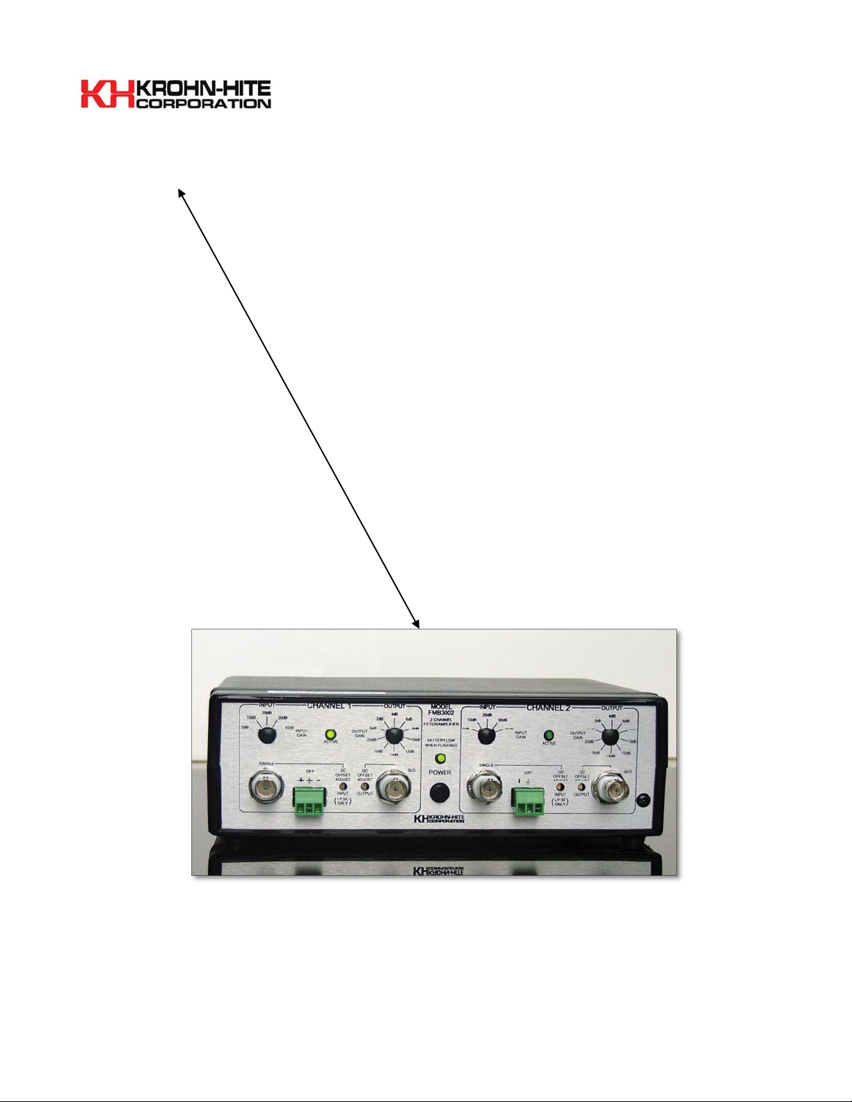
Figure 1.1 Model FMB3002 Filter/Amplifier

This page intentionally left blank.
 Loading...