

Krohn-Hite 7008 Operating Manual
Model 7008
Remote Programmable
Up to 8 Channel Low Noise
Differential Preamplifier
Operating Manual

Service and Warranty
Krohn-Hite Instruments are designed and manufactured in accordance with sound engineering
practices and should give long trouble-free service under normal operating conditions. If your
instrument fails to provide satisfactory service, and you are unable to locate the source of trouble,
contact our Service Department at (508) 580-1660, giving all the information available concerning
the failure.
DO NOT return the instrument without our written or verbal authorization to do so. After contacting
us, we will issue a Return Authorization Number which should be referenced on the packing slip and
purchase order. In most cases, we will be able to supply you with the information necessary to
repair the instrument, avoiding any transportation problems and costs. When it becomes necessary
to return the instrument to the factory, kindly pack it carefully and ship it to us prepaid.
All Krohn-Hite products are warranted against defective materials and workmanship. This warranty
applies for a period of one year from the date of delivery to the Original Purchaser. Any instrument
that is found within the one year warranty period not to meet these standards will be repaired or
replaced. This warranty does not apply to fuses or batteries. No other warranty is expressed or
implied.
Krohn-Hite Corporation reserves the right to make design changes at any time without incurring any
obligation to incorporate these changes in instruments previously purchased.
Modifications to this instrument must not be made without the written consent of an authorized
employee of Krohn-Hite Corporation.

Unit 4, 15 Jonathan Drive, Brockton, MA 02301
-
5566
Model 7008
Remote Programmable 8 Channel
Low Noise Differential Preamplifier
OPERATING MANUAL
E-mail: sales@krohn-hite.com; Web: www.krohn-hite.com
Copyright© 2014 Krohn-Hite Corporation. All rights reserved. No part of this publication may be
reproduced, stored in a retrieval system or transmitted in any form by any means, electronic,
mechanical photocopying, recording, or otherwise, without the prior written permission of KrohnHite Corporation.
Tel: (508) 580-1660; Fax: (508) 583-8989
7008ManRev2.docx
V2.0 Dated: 02/14
Model 7008, 8 Channel Low Noise Differential Preamplifier

TABLE OF CONTENTS
GENERAL INFORMATION ...................................................................................................................... iv
Certification ................................................................................................................................. iv
Warranty. ..................................................................................................................................... iv
Safety and Preparation for Use. .................................................................................................. iv
Line Voltage. ................................................................................................................................ iv
Line Fuse. ..................................................................................................................................... iv
Line Cord. ..................................................................................................................................... iv
Warranty Service. ........................................................................................................................ iv
Service.......................................................................................................................................... iv
Repackaging for Shipment. .......................................................................................................... iv
Definitions. ................................................................................................................................... iv
SECTION 1 - GENERAL DESCRIPTION ..................................................................................................... 5
1.1 INTRODUCTION............................................................................................................................. 5
1.2 SPECIFICATIONS ............................................................................................................................ 5
1.2.1 INPUT .................................................................................................................................. 5
1.2.2 OUTPUT ............................................................................................................................... 6
1.2.3 100kHz FILTER ..................................................................................................................... 7
1.2.4 FRONT PANEL ...................................................................................................................... 7
1.2.5 GENERAL ............................................................................................................................. 7
1.2.6 OPTIONS .............................................................................................................................. 7
1.2.7 ACCESSORIES ....................................................................................................................... 8
SECTION 2 - OPERATION ........................................................................................................................ 9
2.1 INTRODUCTION............................................................................................................................. 9
2.2 POWER REQUIREMENTS ............................................................................................................... 9
2.3 TURN-ON PROCEDURE.................................................................................................................. 9
2.4 FRONT PANEL DISPLAY AND CONTROLS ..................................................................................... 10
2.4.1 MODE ................................................................................................................................ 10
2.4.1.1 LCL (local mode) ............................................................................................... 10
2.4.1.2 EDIT (edit mode) ............................................................................................... 10
2.4.1.3 REMOTE (remote mode) .................................................................................. 11
2.4.2 CHANNEL UP, CHANNEL DOWN CONTROL ....................................................................... 12
2.4.3 SETTING PARAMETERS ...................................................................................................... 13
2.4.3.1 INPUT CONFIGURATION ................................................................................... 13
i

2.4.3.2 100kHz LOW-PASS FILTER ................................................................................. 15
2.4.3.3 INPUT COUPLING .............................................................................................. 15
2.4.3.4 GAIN .................................................................................................................. 16
2.4.3.5 SHUNT (OHMS) ................................................................................................. 17
2.4.4 DC OFFSET ......................................................................................................................... 19
2.4.5 INPUT + AND - BNC CONNECTORS .................................................................................... 19
SECTION 3 - INCOMING ACCEPTANCE ................................................................................................. 21
3.1 INTRODUCTION ........................................................................................................................... 21
3.2 TEST EQUIPMENT REQUIRED ...................................................................................................... 21
3.3 GAIN ACCURACY ......................................................................................................................... 21
3.4 NOISE CHECK............................................................................................................................... 22
3.5 COMMON MODE REJECTION...................................................................................................... 22
3.6 DISTORTION CHECK .................................................................................................................... 22
3.7 AC/DC COUPLING CHECK ............................................................................................................ 22
SECTION 4 - USB-COM OPTION (for Remote Programming) ............................................................... 24
4.1 INTRODUCTION ........................................................................................................................... 24
4.2 USB-COM OPTION ...................................................................................................................... 24
4.2.1 INSTALLING THE DRIVERS ................................................................................................. 25
4.2.2 DRIVER INSTALLATION SEQUENCE ON A WINDOW XP™ S ............................................... 25
4.2.2 HOW TO SET-UP/RUN WINDOWS™ HYPER-TERMINAL ON WINDOWS XP™ SYSTEM ...... 27
4.2.3 AN ALTERNATE TO HYPER-TERMINAL OPERATION .......................................................... 31
4.3 MODEL 7008 PROGRAMMING COMMANDS .............................................................................. 33
4.3.1 TABLE OF COMMANDS ..................................................................................................... 34
4.3.2 COMMAND STRING EXAMPLES ........................................................................................ 34
4.3.3 REPSONSE TO A COMMAND STRING ................................................................................ 35
SECTION 5 - LAN-COM OPTION (for Remote Programming) ............................................................... 36
5.1 INTRODUCTION ........................................................................................................................... 36
5.1.1 SITE LANs AND PRIVATE LANs ........................................................................................... 36
5.1.2 CONNECTING THROUGH A NETWORK .............................................................................. 36
5.1.3 CONNECTING DIRECTLY TO THE MODEL 7008 (no network) ........................................... 36
5.1.4 HOW TO FIND THE CURRENT IP ADDRESS ........................................................................ 36
5.1.5 SETTING A FIXED IP ADDRESS ........................................................................................... 38
5.1.6 LAN and HyperTerminal Setup .......................................................................................... 41
5.1.7 How to Set-Up and Run Windows™ HyperTerminal ......................................................... 41
ii

SECTION 6 - REMOVING AND INSTALLING PREAMPLIFIER CARDS ..................................................... 44
6.1 INTRODUCTION........................................................................................................................... 44
6.2 REMOVING A MODEL 700 PREAMPLIFIER CARD ........................................................................ 44
6.3 INSTALLING THE MODEL 700 PREAMPLIFIER CARD ................................................................... 46
iii

GENERAL INFORMATION
Certification - Krohn-Hite certifies that this product meets published specifications at the time of
shipment.
Warranty - This Krohn-Hite Corporation product is warranted against defects in materials and
workmanship for a period of one (1) year from the date of shipment.
Safety and Preparation for Use - Dangerous voltages, capable of causing injury or death, are present
in this instrument.
Warning! Use extreme caution whenever the instrument covers are removed. Do not remove the
covers while the unit is plugged into a live outlet.
Line Voltage - The Model 7008 accommodates any voltage in the range 105Vac to 132Vac or 210Vac
to 264Vac, with a frequency in the range 50Hz to 60Hz.
Line Fuse - The line fuse is located on the rear of the 7008. The fuse is a 3/4A slow-blow for 120V
applications and a 3/8A slow-blow for 240V applications.
Line Cord - The Model 7008 has a detachable, three-wire power cord for connection to the power
source and to a protective ground. The exposed metal parts of the instrument are connected to the
outlet ground to protect against electrical shock. Always use an outlet which has a properly
connected protective ground.
Warranty Service - For warranty or repair service, this product must be returned to a Krohn-Hite
Corporation authorized service facility or to Krohn-Hite directly. Contact must be made with KrohnHite Corporation or an authorized representative to receive a Return Authorization before returning
this product for repair.
Service - Do not attempt to service or adjust this instrument unless another person, capable of
providing first aid or resuscitation, is present. Do not install substitute parts or perform any
unauthorized modifications to this instrument. Contact the factory for instructions on how to return
the instrument for authorized service and adjustment. The Model 7008 is not intended for hotswapping applications. Be certain to switch power off before inserting or removing plug-in cards in
the chassis.
Repackaging for Shipment - The original packing materials should be saved for reshipment of the
Model 7008 if needed. If the original packing materials are not available, wrap the instrument in
polyethylene sheeting or equivalent and place in a strong box, cushioning it on all sides by at least
three inches of high-density foam or other filler material.
Definitions - A Bracket set [ ] indicates a button.
iv

Section 2 – Operation
Maximum Power
50 0.05 2.5 0.125
500 0.016
8
0.128
5,000 (5k)
0.002
10* 0.020
50,000 (50k)
0.0002
10* 0.002
*Maximum power limited by maximum voltage of 10V.
________________________________________________________________________________
SECTION 1
GENERAL DESCRIPTION
1.1 INTRODUCTION
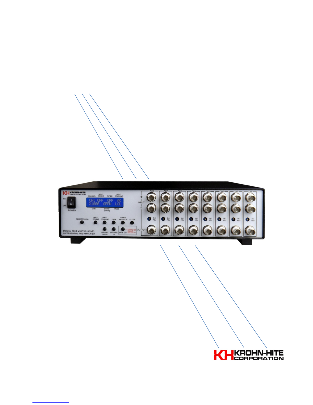
The Krohn-Hite Model 7008 is a two to eight channel Differential Preamplifier providing low noise
and high gain amplification to 1MHz. The output of the 7008 is derived from using a very low noise
FET instrumentation amplifier. Noise referred to input is 7nV√Hz and common mode rejection is
>100dB at 1kHz. The Model 7008 has fixed gain settings of x1 (0dB), x10 (20dB), x100 (40dB) and
x1000 (60dB).
The 7008 provides momentary pushbutton switches that control input coupling, 100kHz filtering
(std), gain, channel selection, shunt resistor for low level signal applications, input configuration and
local/remote/edit selections. BNC connectors are provided for single-ended and differential input
configurations, and for the amplified output. All settings can be edited and monitored with the 16
character, 2-line front panel display.
Optional USB or LAN remote control is available for the 7008. All front panel functions, with the
exception of power on, can be controlled remotely with either option. See Section 3 for
programming information.
The 7008 is an excellent preamp for amplifying low level input signals to oscilloscopes or other
devices. The 7008 is also very useful for troubleshooting sources of noise, amplifiers, power supplies
and various other electronic circuits.
1.2 SPECIFICATIONS
1.2.1 INPUT
Configurations: Single-ended and differential, selectable.
Coupling: AC (0.16Hz, 0.16mHz with option 10 installed) and DC, selectable.
Impedance: 1M ohm (1G ohm with option 10 installed) shunted by 40pF. Each input may be
independently enabled or grounded.
Input Shunt Resistor: 50, 500, 5k and 50k ohm ±0.3%, and open, selectable.
Resistor Value
(1/4W, ohms)
Maximum
Current
(amps)
Maximum
Voltage
Across Shunt
Resistor
(watts)
5
Section 2 – Operation
Freq
Gain = 1 G
ain = 10 to 1k
50Hz
>90dB
>102dB
10kHz
>75dB
>87dB
50kHz
>60dB
>72dB
100kHz
100kHz
Option 11
1 120 90 40
10 14 9 4
100 10 3.2 0.85
1k 10 3.2 0.85
_________________________________________________________________________________
Maximum Input Voltage: 10V peak with gain set to x1.
Max Safe Voltage: Any continuous voltage between ±30V (for 7008-10 option: ±15V).
Gains: x1 (0dB), x10 (20dB), x100 (40dB), x1000 (60dB), selectable.
Accuracy: ±0.3dB.
Stability: 200ppm/°C.
Bias Current: ±5pA typical, 50pA max.
CMMR:
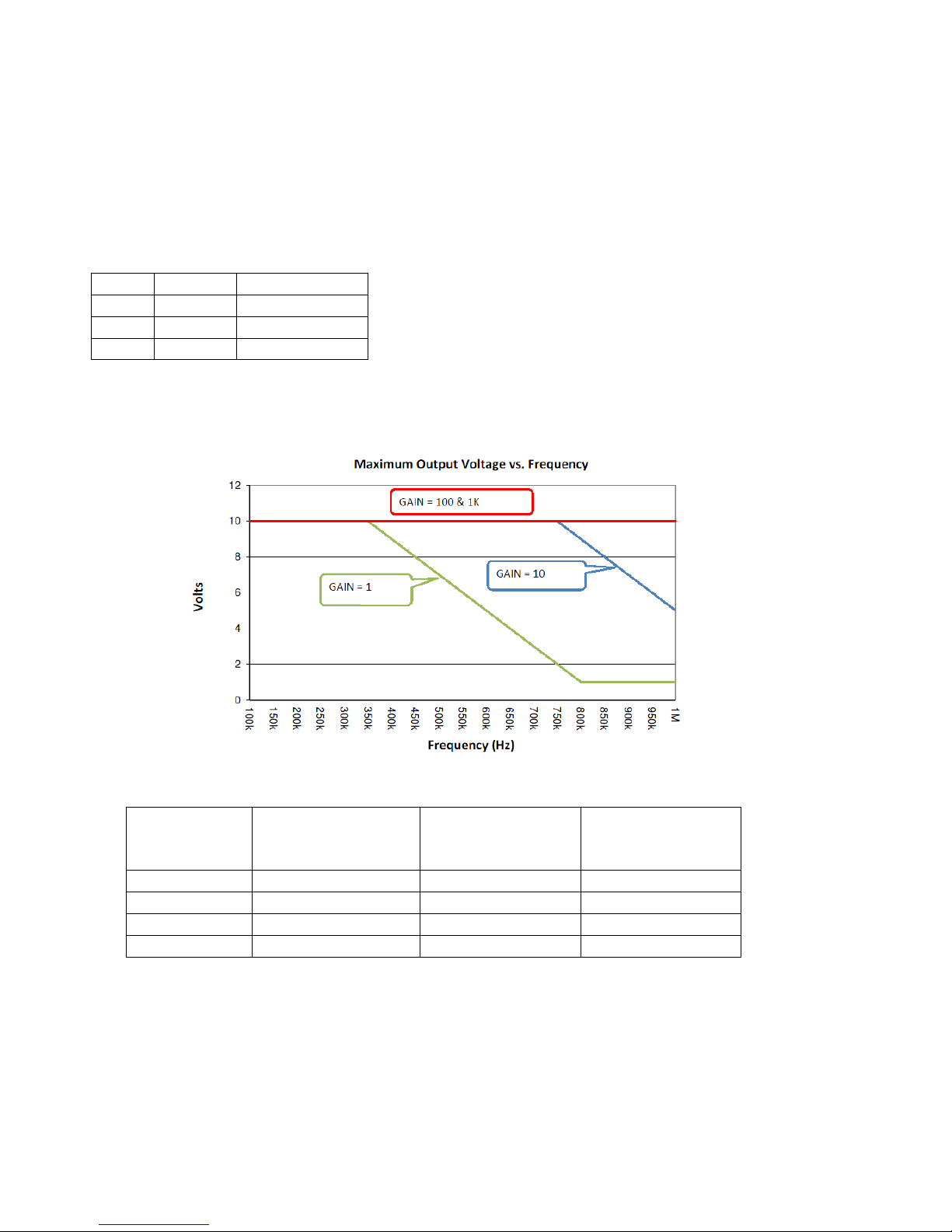
1.2.2 OUTPUT
Maximum Output Voltage: 10V peak.
Frequency Response:
Wideband Noise (Referred to input, 2MHz Bandwidth Detector)
GAIN
FILTER OFF
(µVrms)
FILTER ON
(µVrms)
Noise Density (x1k gain setting, filter off): 7nV/√Hz typical.
Impedance: 50 ohms, single-ended.
Distortion: 0.005% (-85dB) at 1kHz.
Offset Voltage: Adjustable to zero.
6
400Hz Filter
(µVrms)

Section 2 – Operation
________________________________________________________________________________
1.2.3 100kHz FILTER
Cutoff Frequency: 100kHz (option 11, 400Hz; replaces 100kHz filter), 2-pole, 12dB/octave;
selectable. Selections are on and off.
1.2.4 FRONT PANEL
Momentary Pushbutton Switches: For setting Channel, Input Configuration, 100kHz Filter, Input
Coupling, Gain,
Shunt Resistor and Local/Remote/Edit modes of operation.
DC Offset Adjustment Potentiometer: Range, approximately ±30mVdc.
Display: 2-line, 16 character.
1.2.5 GENERAL
Power Requirements: Switch selectable, 90-130, 210-260 volts, single-phase, 50-60Hz, 50W.
Protection: Input overload protection with automatic recovery.
Isolation to Chassis: ±200Vdc.
Operating Temperature: 0°C to +45°C.
Storage Temperature: -25°C to +70°C.
Dimensions: 4“ (10.28cm) high with feet, 3.5" (9cm) high without feet; 14.15" (36.36cm) wide; 14.3”
(36.75cm) deep.
Weights: 12 lbs (5.4kg) net, 14 lbs (6.3kg) shipping.
Certification: A Certificate of Compliance is issued with each new instrument to certify the
calibration and traceability to N.I.S.T.
Warranty: ONE FULL YEAR warranty on parts and labor includes specifications and performance.
1.2.6 OPTIONS
LAN-COM: LAN remote control.
USB-COM: USB remote control.
Option 10: Input impedance is 1G ohm.
Option 11: 400Hz filter in place of 100kHz filter.
Extended 1 Year Warranty: Part No. EW7008.
7
Section 2 – Operation
_________________________________________________________________________________
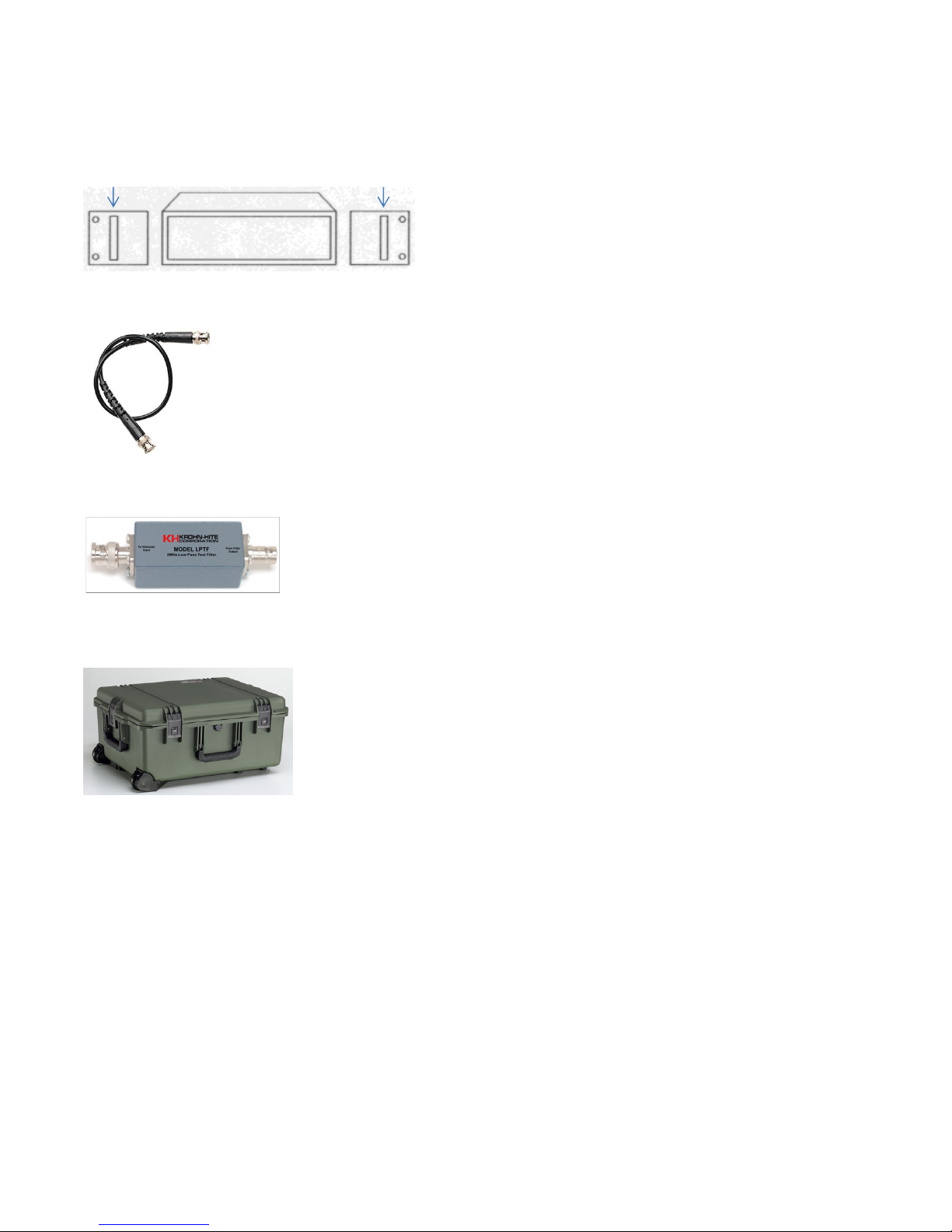
1.2.7 ACCESSORIES
Rack Mount Kit: Part No. RK-314 consists of 2 angle brackets with handles that permit the
installation of the Model 7008 into a standard, 19" rack spacing.
CAB-025: Cable, BNC, 3ft, Low Noise.
LPNF: 2MHz Low-Pass Noise Filter
2720B: Carrying Case
Specifications is subject to change without notice.
8
Section 2 – Operation
WARNING!
CAUTION!
________________________________________________________________________________
SECTION 2
OPERATION
2.1 INTRODUCTION
This section describes the basic operation of the Model 7008. It includes the proper power
requirements, the recommended turn-on procedure and a detailed explanation of all operating
controls, modes of operation and special optional features.
2.2 POWER REQUIREMENTS
The Model 7008 is designed to operate from a single phase, 50-60Hz, ac power source of 105-132,
210-264 volts. This unit is set for 115V operation at the time of shipment. Fuse requirement is 0.75A
(120V) or 0.375A (230V) slow, blow with a 250V rating.
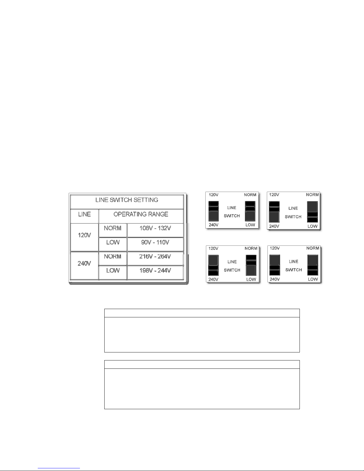
2.3 TURN-ON PROCEDURE
Before turning on the 7008, check to see that the line switches on the rear panel are set to the
correct AC Power Line requirements for your area. Refer to the chart below.
Make sure the POWER switch is in the OFF position. Plug the line cord into the unit and then into the
ac outlet.
The chassis of this instrument is connected to earth ground. For safety
purposes, connect the line cord to a grounded, 3 terminal ac outlet.
Because of the potentially dangerous voltages that exist within the
unit, the cover should not be removed when the instrument is
connected to an ac power source.
The unit is now ready to operate. For low noise applications, it is recommended to use Krohn-Hite’s
low noise cable, part number CAB-025.
9
Section 2 – Operation
_________________________________________________________________________________
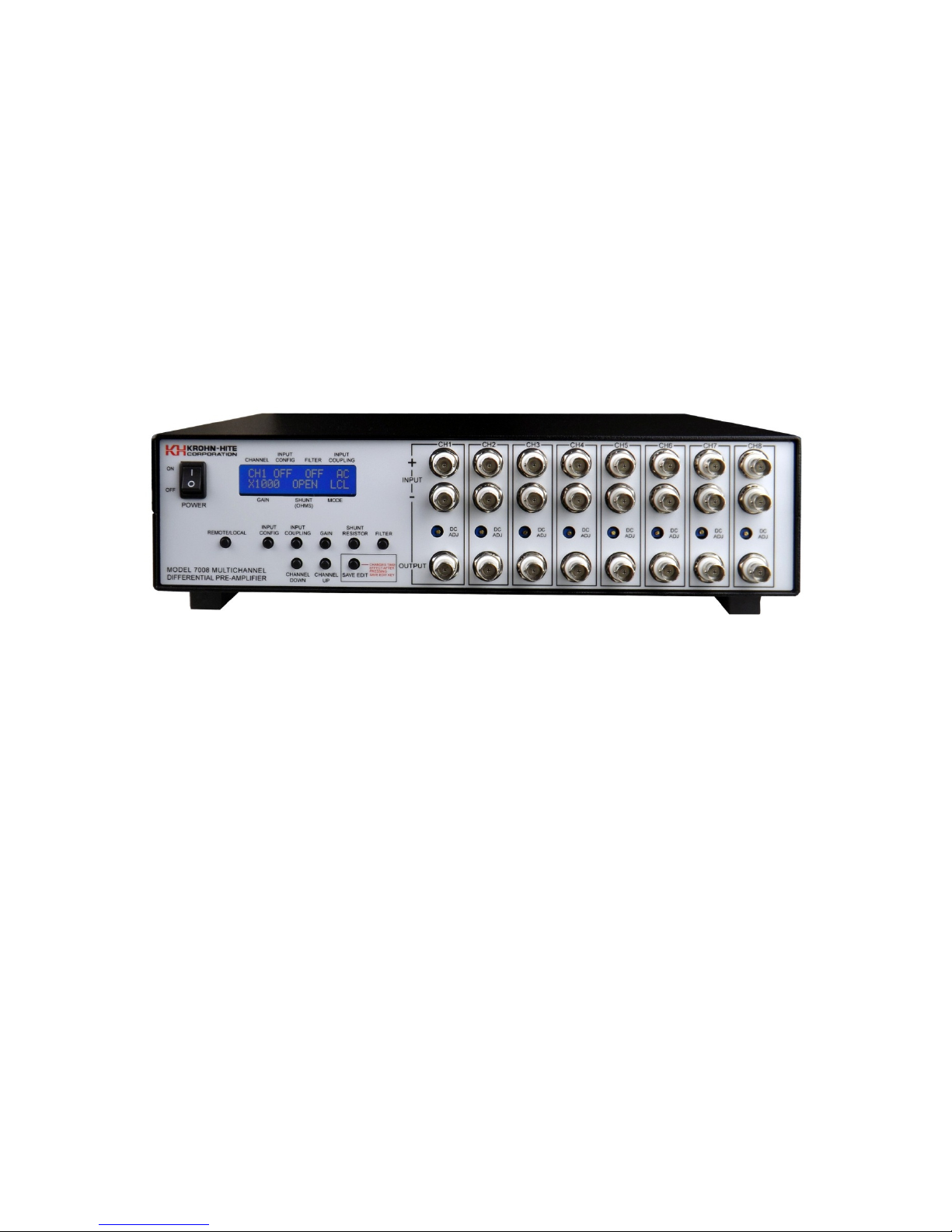
2.4 FRONT PANEL DISPLAY AND CONTROLS
The Model 7008 provides a 16-character, 2-line DISPLAY that indicates the status of all parameters
and modes of each channel as shown in Figure 2.1 below. When turn-on, the display will indicate:
Krohn-Hite 7008. All functions are available by front panel control and remote control. An audible
beep for tactile feel is provided and will sound with each button press.
2.4.1 MODE
The 7008 provides 3 Modes of operation, Remote, Local and Edit. Remote and local modes are
controlled by pressing the [LOCAL/REMOTE] button. Edit mode becomes active when a parameter is
changed when in the local mode. See EDIT below for full details.
a) LCL, local control
b) REMOTE, remote control
c) EDIT, Edit mode (You will need to press [SAVE EDIT] to change output settings once
altered.)
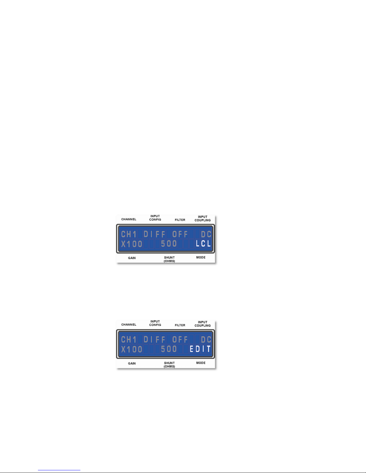
2.4.1.1 LCL (local mode)
When LCL is displayed all front panel controls are active. Pressing the [LOCAL/REMOTE] button will
return the 7008 to remote control.
Figure 2.1 – Local Mode Display
2.4.1.2 EDIT (edit mode)
The EDIT mode becomes active whenever a parameter button is pressed. In this mode you can
changed the settings of any or all channels if desired and saved to non-volatile memory.
Figure 2.2 – EDIT Mode Display
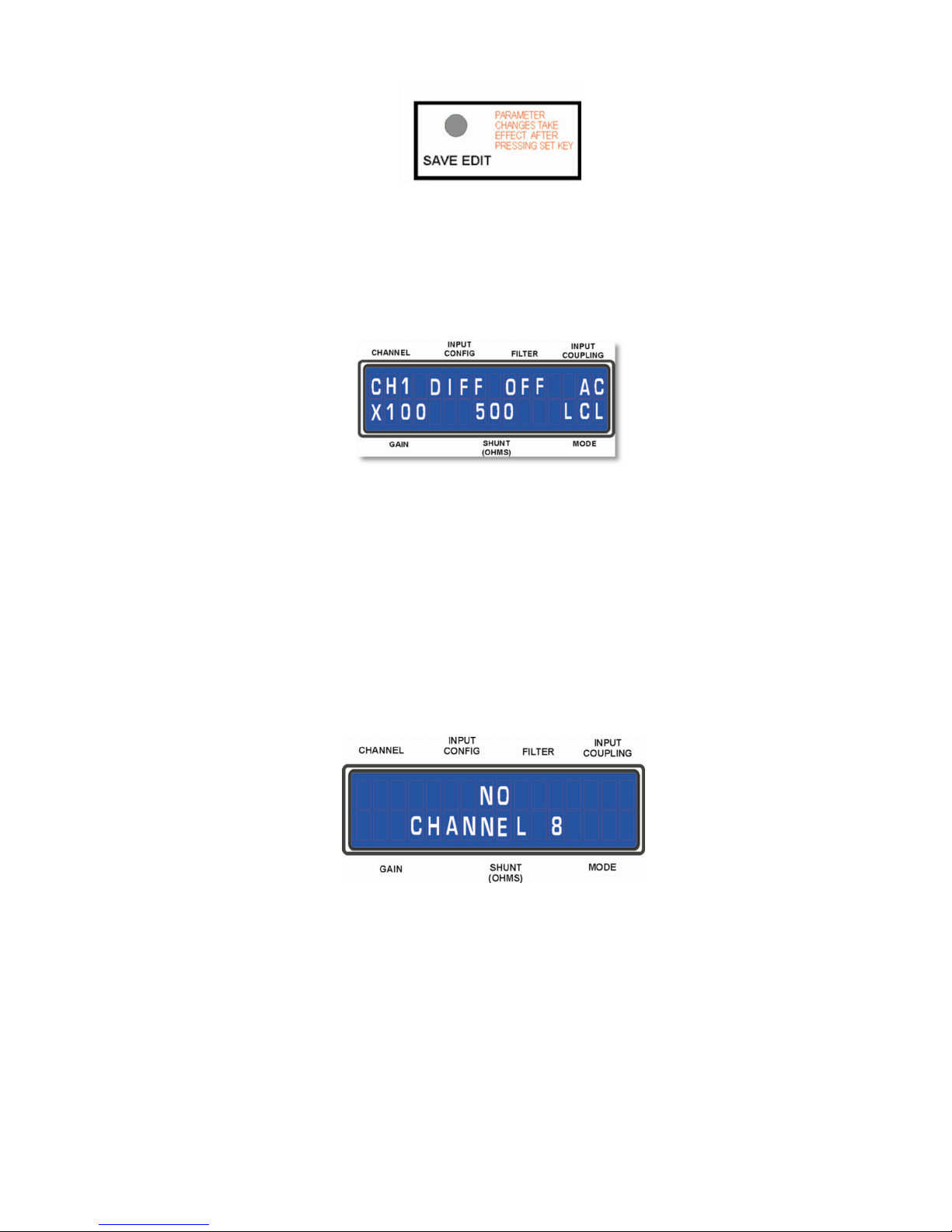
Once the parameter change(s) are set, pressing the [SAVE EDIT] button will save the setting for that
channel. If in ALL channel, all parameter changes will be saved to all channels.
10
Section 2 – Operation
________________________________________________________________________________
Figure 2.3 – [SAVE EDIT] Mode Button
Parameters are changed by pressing the button associated with that parameter. When a button is
pressed, the LCL display will change to EDIT indicating that you have entered the EDIT mode and will
need to press the [SAVE EDIT] button to save one or all changes made to that channel.
Figure 2.4 – Front Panel Display
When the CHANNEL display indicates ALL, dashes will appear in the display, indicating that a
parameters need to be set. In this mode, all parameters have to be entered with a value or the
display will indicate the following:
Not All
Parameters Set
If a Channel is defective or there is no card in a Channel slot, the display will indicate a NO CHANNEL
with the Channel number that is missing or defective as indicated in Figure 2.5 below.
Figure 2.5 – Missing or Defective Card
2.4.1.3 REMOTE (remote mode)
When REMOTE is displayed all front panel control are disabled, with the exception of the
[LOCAL/REMOTE] button. When in Remote mode, pressing this button will return the 7008 to local
control.
11

Section 2 – Operation
_________________________________________________________________________________
Figure 2.6 – Remote Mode Display
ERROR INDICATOR
When the 7008 is placed into the REMOTE mode, a beep tone is activated. When any parameter
button is pressed, a beep tone will sound, indicating the 7008 is in REMOTE operation. Pressing the
[REMOTE/LOCAL] button toggles between REMOTE and LOCAL, and when the 7008 is in REMOTE,
will return the unit to LOCAL operation.
2.4.2 CHANNEL UP, CHANNEL DOWN CONTROL
Pressing the [CHANNEL UP] and [CHANNEL DOWN] buttons will display each channel’s current setup.
Figure 2.7 – [Channel Up] Button Figure 2.8 [Channel Down] Button
Each channel’s parameters are entered independently or all at one time when in the ALL channel
mode. When setting or changing a specific channel’s parameters, the output signal for that channel
will not change until the [SAVE EDIT] button is pressed. The same is true for the ALL channel mode.
If a parameter is changed, and [CHANNEL UP] or [CHANNEL DOWN] button is pressed before the
[SAVE EDIT] button, the parameters will not change. Pressing the [SAVE EDIT] button will then
change the parameter(s) to the values selected.
12
 Loading...