

Krohn-Hite 526 Operating Manual
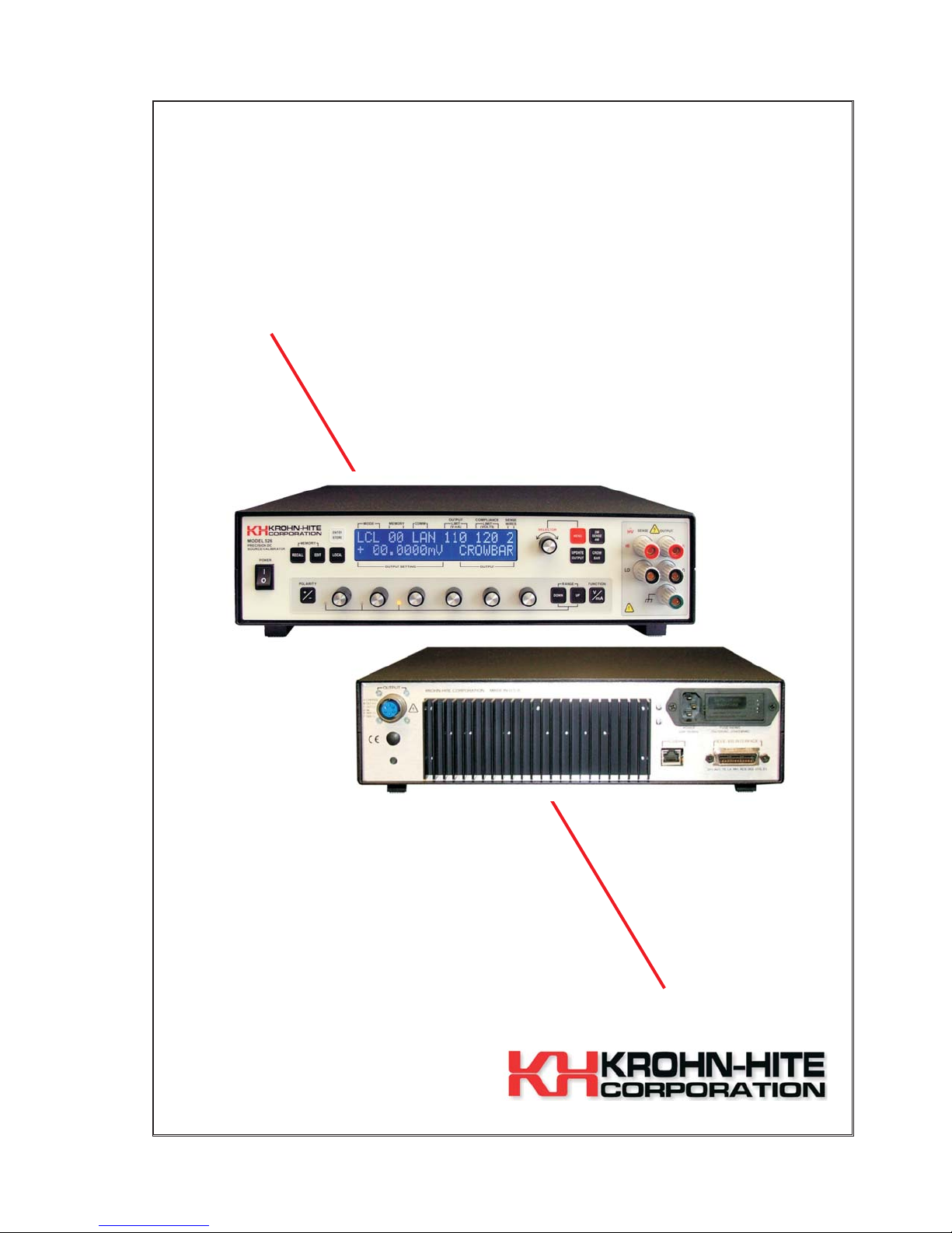
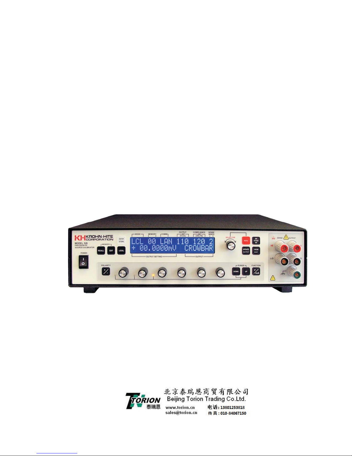
Model 526
Precision DC Source/Calibrator
±100nV to ±111V
±10nA to ±111mA
Operating Manual

Service and Warranty
Krohn-Hite Instruments are designed and manufactured in accordance with sound engineering practices and
should give long trouble-free service under normal operating conditions. If your instrument fails to provide
satisfactory service and you are unable to locate the source of trouble, contact our Service Department at (508)
580-1660, giving all the information available concerning the failure.
DO NOT return the instrument without our written or verbal authorization to do so. After contacting us, we
will issue a Return Authorization Number which should be referenced on the packing slip and purchase order.
In most cases, we will be able to supply you with the information necessary to repair the instrument, avoiding
any transportation problems and costs. When it becomes necessary to return the instrument to the factory,
kindly pack it carefully and ship it to us prepaid.
All Krohn-Hite products are warranted against defective materials and workmanship. This warranty applies
for a period of one year from the date of delivery to the Original Purchaser. Any instrument that is found
within the one year warranty period not to meet these standards, will be repaired or replaced. This warranty
does not apply to fuses or batteries. No other warranty is expressed or implied.
Krohn-Hite Corporation reserves the right to make design changes at any time without incurring any
obligation to incorporate these changes in instruments previously purchased.
Modifications to this instrument must not be made without the written consent of an authorized employee of
Krohn-Hite Corporation.
Model 526
Precision DC Source/Calibrator
Operating Manual
Copyright 2013. All rights reserved. Contents of this publication may not be reproduced in any form without
the written permission of Krohn-Hite Corporation.
Revision 3.2, Published 6/13, Printed in U.S.A.
15 Jonathan Drive, Unit 4, Brockton, MA 02301-5566
Tel: (508) 580-1660; Fax: (508) 583-8989
sales@Krohn-hite.com; www.krohn-hite.com


Table of Contents
526 Table of Contents
SECTION 1.0 GENERAL DESCRIPTION AND SPECIFICATIONS ..............1-1
1.1 Introduction ....................................1-1
1.2 Specifications ...................................1-2
1.2.1 Voltage Mode Specifications ......................1-2
1.2.2 Current Mode Specifications ......................1-3
1.2.3 GPIB Programming ..........................1-3
1.2.4 Terminals ................................1-4
1.2.5 Modes Of Operation ..........................1-4
1.2.6 Special Features ............................1-4
1.2.7 General Specifications .........................1-4
1.2.8 Safety..................................1-5
1.2.9 Electromagnetic Compatibility .....................1-5
1.2.10 Mechanical Specifications .......................1-5
1.2.11 General Information ..........................1-5
1.2.12 Accessories ..............................1-5
1.2.13 Options .................................1-5
1.2.14 Optional Accessories ..........................1-5
SECTION 2.0 OPERATION ...................................2-1
2.1 Introduction ....................................2-1
2.2 Selecting Line Voltage ..............................2-1
2.3 Placement and Rack Mounting..........................2-3
2.4 Quick Start.....................................2-3
2.4.1 526 Tones ...............................2-3
2.4.2 LOCAL Key...............................2-4
2.4.3 SELECTOR Knob ...........................2-4
2.4.4 Setting a Voltage/Current .......................2-4
2.4.4.1 Decade Controls .......................2-4
2.4.5 Selecting a Range ...........................2-4
2.4.6 Recalling Memory Set-Ups.......................2-5
2.4.7 Saving Set-Ups into Memory......................2-5
2.4.8 Front Panel Output Terminals .....................2-6
i

Table of Contents
2.4.9 Rear Panel Connectors ........................2-7
2.5 Front Panel Controls ...............................2-8
2.5.1 Membrane Keys ............................2-8
2.6 Display Information ...............................2-12
2.6.1 Mode .................................2-12
2.6.2 Memory ................................2-13
2.6.3 Comm .................................2-13
2.6.4 Output Limits (V-mA) .........................2-13
2.6.5 Compliance Limits (VOLTS) .....................2-13
2.6.6 Sense Wires .............................2-14
2.6.7 Output Settings ............................2-14
2.6.8 Output .................................2-14
2.7 Menu and Selector Knob Control........................2-14
2.7.1 Menu 1 - View Set-Up ........................2-15
2.4.8.1 HV Led ............................2-6
2.4.8.2 Wire Connections .......................2-6
2.4.9.1 IEEE-488 Connector .....................2-7
2.4.9.2 Optional LAN Connector (Option: LAN) ............2-7
2.4.9.3 Power Entry Module .....................2-7
2.4.9.4 Rear Panel Output Connector and Mating Connector.....2-8
2.4.9.5 Chassis Ground/Safety Ground................2-8
2.5.1.1 [ENTER/STORE] Key.....................2-8
2.5.1.2 [RECALL] Key ........................2-9
2.5.1.3 [EDIT] Key ..........................2-9
2.5.1.4 [LOCAL] Key .........................2-9
2.5.1.5 [+/-] POLARITY Key .....................2-10
2.5.1.6 [DOWN] and [UP] RANGE Keys ...............2-10
2.5.1.7 [VOLTS/MILLI AMP] Key ..................2-10
2.5.1.8 [CROWBAR] Key ......................2-11
2.5.1.9 [2W SENSE 4W] Key ....................2-11
2.5.1.10 [UPDATE OUTPUT] Key ..................2-11
2.5.1.11 [MENU] Key .........................2-11
2.7.1.1 Port Setting View ......................2-15
2.7.1.2 Voltage Limits View .....................2-16
2.7.1.3 Current Limit View ......................2-16
2.7.1.4 Compliance Voltage View ..................2-16
2.7.1.5 Power On Sequence View ..................2-16
2.7.1.6 Full or Partial Display View..................2-17
ii

Table of Contents
2.7.1.7 Pass Thru Zero View ....................2-17
2.7.1.8 Remote Protocol View ....................2-17
2.7.1.9 Exiting To Main Level ....................2-18
2.7.1.10 Exiting Menu and Returning To Local Operation.......2-18
2.7.2 Menu 2 - Port Selection........................2-18
2.7.2.1 IEEE-488 (GPIB) ......................2-19
2.7.2.2 LAN (Optional)........................2-20
2.7.3 Menu3-VOutput Limit........................2-20
2.7.4 Menu 4 I Output Limit ........................2-22
2.7.5 Menu 5 V Compliance Limit (Fail Safe)...............2-23
2.7.5.1 Changing V Compliance Limit ................2-23
2.7.6 Menu 6 - Power-On Set-Up......................2-24
2.7.6.1 Changing Power-On Set-Up Setting .............2-25
2.7.7 Menu 7 - Display Area........................2-26
2.7.7.1 Changing Display Area Setting ...............2-26
2.7.8 Menu 8 - Pass Thru Zero ......................2-27
2.7.8.1 Changing Pass Thru Zero Setting:..............2-27
2.7.9 Menu 9 - CLR User Memory ....................2-28
2.7.9.1 Clearing User Memory....................2-28
2.7.10 Menu 10 - Remote Protocol .....................2-28
2.7.11 Changing Remote Protocol Setting ..................2-29
2.8 Overloading ...................................2-29
SECTION 3.0 526 (STD) GPIB PROGRAMMING .......................3-1
3.1 Introduction ....................................3-1
3.2 Krohn-Hite (Std) Programming Protocols....................3-1
3.3 IEEE-488 (GPIB) Programming..........................3-2
3.3.1 Interface Capabilities ..........................3-2
3.3.2 Setting The Instrument’s Address ...................3-2
3.3.3 Interface Messages ..........................3-2
3.3.3.1 “MLA” - My Listen Address. ..................3-2
3.3.3.2 “MTA” - My Talk Address ...................3-2
3.3.3.3 “UNL” Unlisten ........................3-2
3.3.3.4 “IFC” Interface Clear .....................3-2
3.3.3.5 “Power-On” Clear .......................3-2
3.3.4 Group Commands ...........................3-3
3.3.5 Output Data Byte String Format ....................3-4
3.3.5.1 Examples of Data Strings/Output Results ...........3-5
iii

Table of Contents
3.3.6 Talk Enable Modes...........................3-5
3.3.7 C or c (Compliance Limit) .......................3-5
3.3.8 *RST or *rst (Power-Up Reset) ....................3-5
3.3.9 S or s (Status) .............................3-5
3.3.10 M or m (Set Memory)..........................3-8
3.3.11 L or l (Output Limit) ...........................3-8
3.3.12 *IDN? or *idn? .............................3-8
3.3.13 ? (What's Wrong Query) ........................3-8
3.3.14 "What’s Wrong" Request ........................3-8
3.3.15 Programming Examples ........................3-9
SECTION 4.0 MODEL 522 GPIB PROGRAMMING ......................4-1
4.1 Introduction ....................................4-1
4.2 IEEE-488 Programming Protocol ........................4-1
4.2.1 Interface Messages. ..........................4-2
4.2.2 Groups of Commands .........................4-2
4.2.3 Talk Enable Modes...........................4-2
4.2.4 Responses ...............................4-3
4.2.5 Data Byte String Format.........................4-3
4.2.6 What’s wrong request, ("?") ......................4-4
4.2.7 Programming ..............................4-4
4.2.8 IEEE-488 Addressing .........................4-5
SECTION 5.0 MODEL 8200 GPIB PROGRAMMING .....................5-1
5.1 Analogic/Data Precision Protocol ........................5-1
5.1.1 8200 Protocol Programming Examples ................5-2
5.1.2 Address Setting ............................5-3
5.1.3 2-Wire/4-Wire Operation ........................5-3
SECTION 6.0 LAN (LOCAL AREA NETWORK) OPERATION ................6-1
6.1 Introduction ....................................6-1
6.2 Local Area Networks ...............................6-1
6.2.1 Site LANs and Private LANs ......................6-1
6.2.2 Connecting Through a Network ....................6-1
6.2.3 Connecting Directly to the Model 526 (no network) ..........6-1
6.2.4 How to Find the Current IP Address:..................6-1
6.2.5 Setting a Fixed IP Address.......................6-3
6.2.6 LAN and HyperTerminal Setup ....................6-6
6.2.6.1 How to Set-Up and Run WindowsÒ HyperTerminal .....6-6
iv

Table of Contents
SECTION 7.0 INCOMING ACCEPTANCE ...........................7-1
7.1 Introduction ....................................7-1
7.2 Warm-Up Time...................................7-1
7.3 Required Test Equipment ............................7-1
7.4 Preliminary Set-Up ................................7-1
7.5 Verification Procedure ..............................7-2
7.5.1 Output Voltage Checks.........................7-2
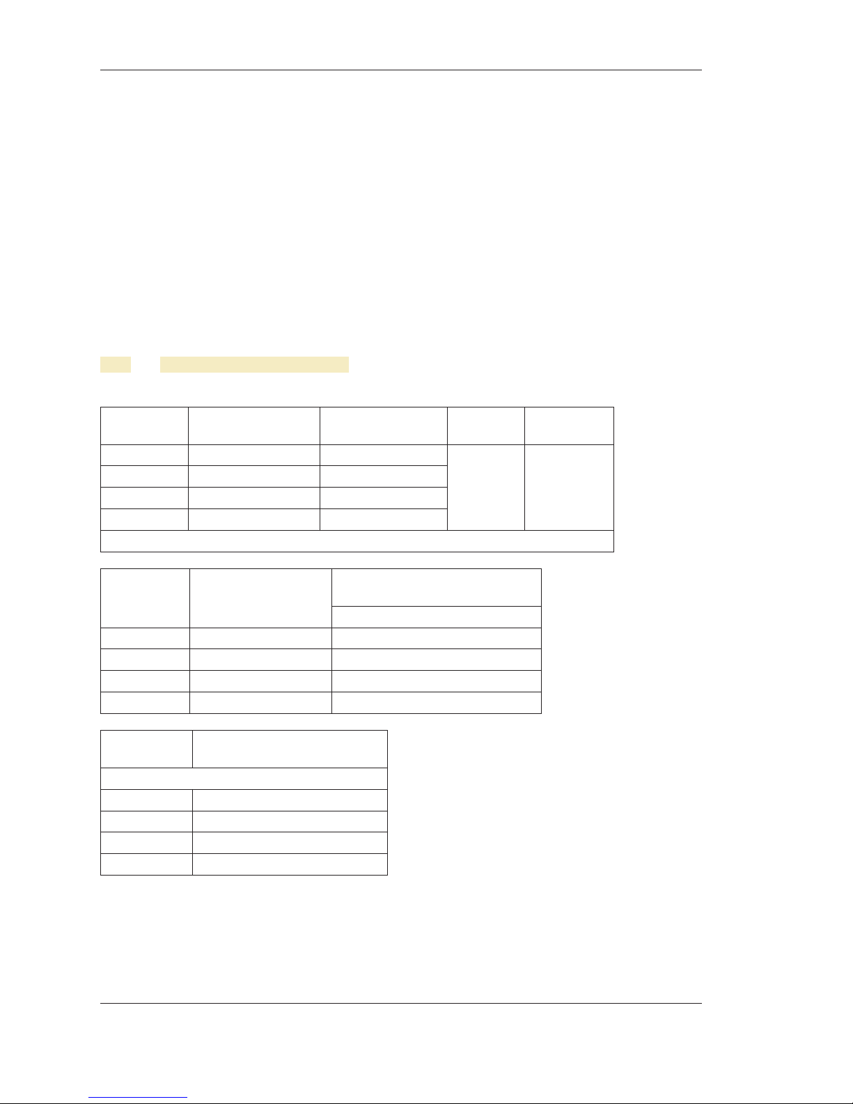
7.5.2 Output Current Checks (using PCR100 Precision Resistor)......7-3
v

Table of Contents
vi

Warranty, Service and Safety
Warranty, Service and Safety
Krohn-Hite Instruments are designed and manufactured in accordance with sound engineering practices and
should give long trouble-free service under normal operating conditions. If your instrument fails to provide
satisfactory service and you are unable to locate the source of trouble, contact our Service Department at (508)
580-1660, giving all the information available concerning the failure.
DO NOT return the instrument without our written or verbal authorization. When contacting us, we will issue
a Return Authorization Number that should be referenced on the packing slip and purchase order. In most
cases, we will be able to supply you with the information necessary to repair the instrument, avoiding any
transportation problems and costs. When it becomes necessary to return the instrument to the factory, kindly
pack the instrument carefully and ship it to us prepaid.
All Krohn-Hite products are warranted against defective materials and workmanship. This warranty applies
for a period of one year from the date of delivery, to the Original Purchaser. Any instrument that is found
within the one-year warranty period not to meet these standards will be repaired or replaced. This warranty
does not apply to fuses or batteries. No other warranty is expressed or implied.
Krohn-Hite Corporation reserves the right to make design changes at any time without incurring any
obligation to incorporate these changes in instruments previously purchased.
Modifications to this instrument must not be made without the written consent of an authorized employee of
Krohn-Hite Corp.
Claims
Immediately upon arrival, purchaser shall check the packing container against the enclosed packing list and
shall, within thirty days of arrival, give Krohn-Hite notice of shortages or any non-conformity with the terms
of the order.
The purchaser assumes all risk of loss or damage to instrument upon delivery by Krohn-Hite to the carrier. If
an instrument is damaged in transit, purchaser must file all claims for damage with the carrier to obtain
compensation. Upon request by purchaser, Krohn-Hite will submit an estimate of cost to repair shipment
damage.
vii

Warranty, Service and Safety
SAFETY ISSUES
Warning
HIGH VOLTAGE is used in the operation of this instrument. LETHAL voltages may be present on the output
terminals. Please observe all safety precautions when operating this instrument.
Power Source
The Model 526 is intended to operate from a 105V to 130V or 210V to 260V ac rms source. A protective
ground connection by way of the grounding conductor in the power cord is essential for safe operation.
Proper Fuse
To avoid damage to the Model 526 or to prevent a fire hazard, use the correct fuse for the line voltage selected.
Proper fuse requirement is screened on the rear panel of the instrument above the power connector.
The Model 526 has been designed, tested and supplied in a safe condition. The following general safety
precautions must be observed during all phases of operation, service, and repair. Failure to comply with these
precautions or with specific warnings elsewhere in this manual violates safety standards of design,
manufacture and intended use of this instrument. Krohn-Hite assumes no liability for the customer’s failure to
comply with these requirements.
This manual contains information and warnings that must be observed to keep the instrument in a safe
condition and ensure safe operation. Operation or service in conditions or in a manner other than specified
could compromise safety. For the correct and safe use of this instrument, operating and service personnel
must follow generally accepted safety procedures.
To avoid injury or fire hazard, do not switch on the instrument if it is damaged or suspected to be faulty. Do
not use the instrument in damp, wet, condensing, dusty or explosive gas environments.
Whenever it is likely that safety protection has been impaired, make the instrument inoperative and secure
against any unintended operation, and then inform qualified personnel. Safety protection is likely to be
impaired if, for example, the instrument shows visible damage, or fails to operate normally.
Ground The Instrument
To minimizeshock hazard, the instrument chassis and cabinet must be connected to an electrical ground. Any
interruption of the protective ground conductor inside or outside the instrument is likely to make the
instrument dangerous. Intentional interruption is prohibited.
Protective Earth Ground
Protective earth symbol located on the inside rear chassis near the AC line filter module designate the point at
which thesafety earth system is attached to the chassis. The symbol must not be altered or removed. The safety
earth wires (green/yellow) must never be disconnected. The safety earth ground wires (green/yellow)
connecting the module must make direct contact with the chassis.
viii
The following are symbols used on the chassis of the 526:
---- Chassis Protective Ground
---- AC (Alternating Current)
---- Conforms to European Union Directives
---- Important Information, Refer to the Manual
Warranty, Service and Safety
---- Caution, Risk of Electric Shock
Do Not Operate In An Explosive Area
Do not operate the instrument in the presence of flammable gases or fumes. Operation of any electrical
instrument in such an environment constitutes a definite safety hazard.
Keep Away From Live Circuits
Operating personnel must not remove instrument covers. Qualified maintenance personnel must make
component replacement and internal adjustments. Under certain conditions, dangerous voltages may exist.
To avoid injuries, always disconnect input voltages before removing the covers.
Do Not Substitute Parts or Modify Instrument
Because of the danger of introducing additional hazards, do not install substitute parts or perform any
unauthorized modifications. Return the unit to the Krohn-Hite Service Department to modify or repair the
instrument to ensure that safety features are maintained.
Do Not Operate a Damaged Instrument
Whenever it is possible that the safety protection features built into this instrument have been impaired, either
through physical damage, excessive moisture, or any other reason, REMOVE the POWER and do not use the
instrument until safe operation can be verified by service-trained personnel. If necessary, return the
instrument to the Krohn-Hite Service Department for service and repair to ensure that the safety features are
maintained.
ix
Warranty, Service and Safety
Do Not Remove Cover
To avoid personal injury, do not remove the covers of the Model 526. There are no user-serviceable parts
inside the instrument, so there is no reason for any user to remove the covers of this instrument.
Unpacking and Inspection
The Model 526 has been shipped in a container designed to prevent any damage from occurring during
shipping. Inspect the 526 carefully for damage, and immediately report any damage to the shipper.
If you need to return the 526 for any reason, use the original container if possible. If not, you can order a new
container from Krohn-Hite Corporation at (508) 580-1660 indicating the model and serial number.
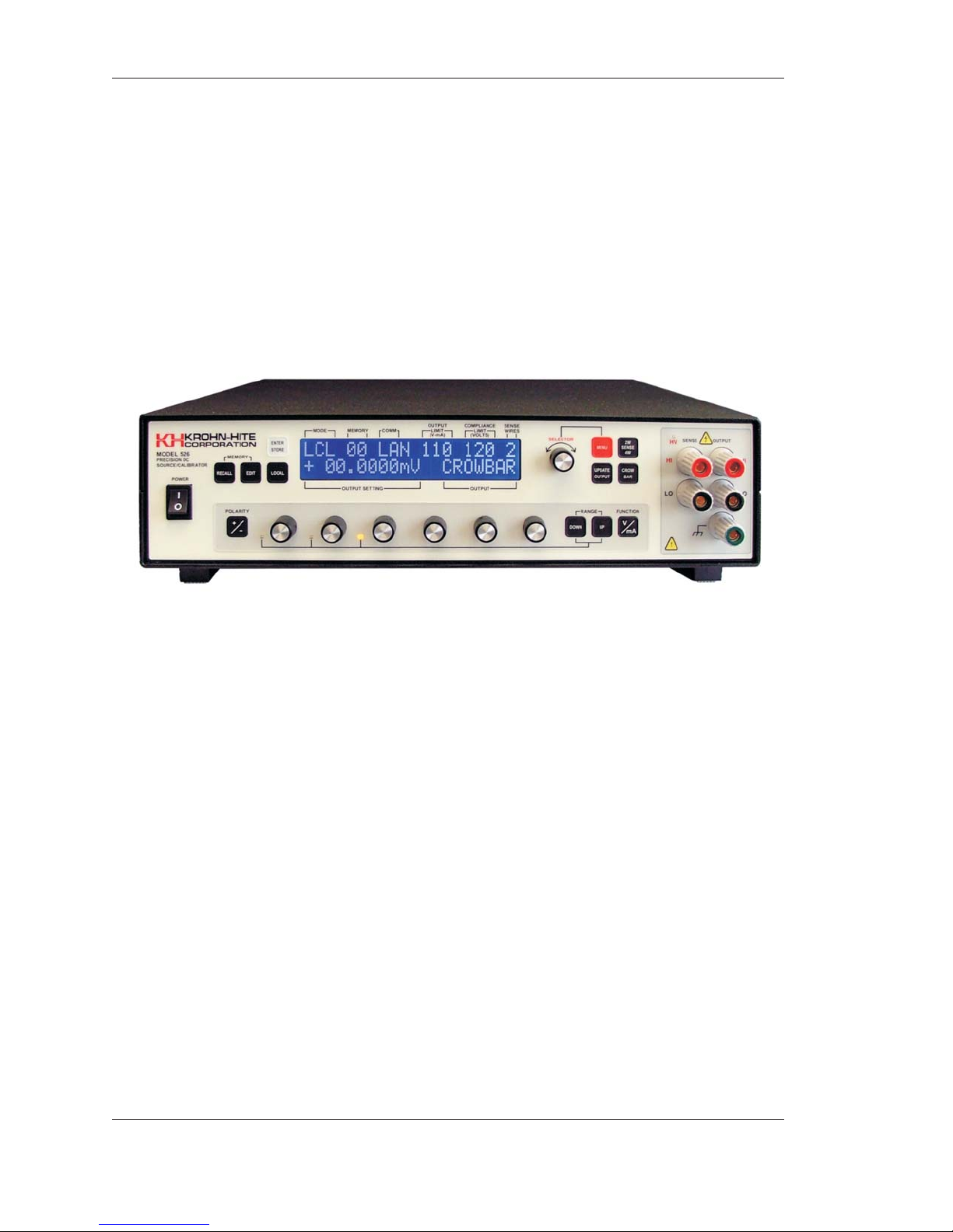
Figure 1 Model 526 Precision DC Source/Calibrator
x

Section 1 - General Description and Specifications
SECTION 1
General Description and Specifications
1.1 Introduction
The Krohn-Hite Model 526 Precision DC Voltage/Current Source/Calibrator is a highly stable and repeatable
DC voltage and DC current source providing N.I.S.T. traceable voltages and currents for use in production,
calibration labs, QA and QC departments, design labs, or any place where an accurate voltage and current
source is needed.
The 526 provides accurate voltages from ±100nVdc to ±111.1110Vdc to within 20ppm for 1 year, and precise
currents from ±10nA to ±111.1110mA to within 50ppm for 1 year. It is an extremely quiet source with
<6μVrms of noise measured over a 10Hz to 100kHz bandwidth.
Decade Control
Microprocessor assisted decade control allows for continual use of one decade with full carry and borrow
capability to and from all more significant decades for easier use and convenient manual operation.
Monotonic and linear A/D measurements can be made at any resolution using only one decade control.
Display and Front Panel Controls
A user friendly 2-line 40 character display and six front panel decade switches with full carry and borrow,
allow for fast accurate voltage and current settings. Output settings can be modified using the front panel
decade switches and the range keys. Output 2-wire, 4-wire operation is accomplished with one keystroke or
over GPIB/LAN. A crowbar function places the output in a safe mode when desired. The 526 output can be
set to 0 volts, allowing the output sense to maintain a true 4-wire low impedance output.
Ranges and Resolution
The 526 provides four voltage ranges of 100mV, 1V, 10V and 100V with a resolution of 100nV, 1μV, 10μV
and 100μV respectively. Two current ranges provide 10mA and 100mA with a resolution of 10nA and 100nA
respectively.
Non-Volatile Memory
Up to 32 storage locations are provided with the 526, that can be recalled at any time.
Voltage and Current Limits
Selecting voltage and current limits to prevent users from damaging sensitive circuitry or devices under test
may be set from the front panel from ±0V to ±112V or 1mA to 112mA.
Output Voltage or Current Compliance Limits
A hardware fail safe compliance limits can be set in the Model 526. Settable limits are: 120V, 36V, 26V or
16V.
1-1
Section 1 - General Description and Specifications
Remote Control
The 526 provides for GPIB and LAN (optional) remote control. Rear panel connectors are provided that allow
connection to a computer. Programming Krohn-Hite and Analogic/DP 8200 protocols are built into the
firmware, allowing the 526 to be used in any system with the older Model 521/522 and Analogic/DP Model
8200.
Applications
The 526 is well suited for a variety of applications such as: the design, check and calibration of high speed,
high resolution A/D converters; design and certification of high speed data logging and process control
systems; calibration of digital voltmeters and multimeters; as an “IMBEDDED STANDARD” and/or
simulator; design, testing, simulation and certification of thermocouples, strain gages and transducer
instrumentation. It is also a replacement for the Analogic Model 8200.
1.2 Specifications
1.2.1 Voltage Mode Specifications
Specifications apply at 23ºC ±1ºC, <70% relative humidity.
Range Full Scale Resolution
100mVdc ±111.1110mVdc 100nVdc
1.0Vdc ±1.111110Vdc 1μVdc
10Vdc ±11.11110Vdc 10μVdc
100Vdc ±111.1110Vdc 100μVdc
Short Circuit Current: 200mA max.
Absolute Accuracy
±(ppm of setting + μV)
Range Full Scale
100mVdc ±111.1110mVdc 20 + 3
1.0Vdc ±1.111110Vdc 20 + 5
10Vdc ±11.11110Vdc 20 + 52
100Vdc ±111.1110Vdc 20 + 500
24 Hour Stability *
Range
* 24 hour stability applies at 23ºC, ±1ºC
100mVdc ±3 + 1.5
1Vdc ±3 + 1.5
10Vdc ±3 + 10
100Vdc ±3 + 100
±(ppm of setting + μV)
1Year
Current
(dc)
100mA 20μ
Zo
(ohms)
Temperature Coefficient: 18ºC to 28ºC, ±5ppm of setting, ±1ppm of range/ºC; operating limit, ±10ppm of
setting, ±2ppm of range/ºC.
Settling Times: 100mV, 1V and 10V range, 2ms; 100V range, 15ms; range changes, 35ms.
Line Regulation: ±2ppm of setting for a 10% line fluctuation.
1-2
Section 1 - General Description and Specifications
Load Regulation 4-Wire operation: <±2ppm + 1μV of setting from no load to 100mA full load.
Measurements must be made at sense lead connection point to the load.
Noise and Ripple (rms):
Bandwidth
Range
100mVdc 2μVp-p 6μVrms
1Vdc 2μVp-p 10μVrms
10Vdc 4μVp-p 20μVrms
100V 40μVp-p 100μVrms
1.2.2 Current Mode Specifications
Range Full Scale
10mAdc ±11.11110mAdc 50 + 50
100mAdc ±111.1110mAdc 50 + 200
0.1Hz to 10Hz 10Hz to 100kHz
Absolute Accuracy
±(ppm of setting + nA)
1Year
Voltage
Range Full Scale Resolution
10mAdc ±11.11110mAdc 10nAdc 100Vdc
100mAdc ±111.1110mAdc 100nAdc 100Vdc
Noise and Ripple (rms):
Bandwidth
Range
10mAdc 25nAp-p 150nArms
100mAdc 100nAp-p 300nArms
Temperature Coefficient: 18ºC to 28ºC, ±5ppm of setting, ±1ppm of range/°C; operating limit, ±10ppm of
setting, ±2ppm of range/°C.
Maximum Output Current: ±111mA. Output protected from damage with a current limiter. Output may be
shorted to ground indefinitely.
Line Regulation: ±2ppm of setting for a 10% line fluctuation.
Compliance Voltage Effect: <±2ppm + 1μV of setting for a 90V change in compliance voltage change.
1.2.3 GPIB Programming
Subsets: SH1, AH1, T6, L4, SR1, RL0, PP1, DC0, DT0, E1.
0.1Hz to 10Hz 10Hz to 100kHz
Compliance
Line Termination: The GPIB EOI signal is always sent with the last character on a line.
Talker Function: Allows interrogation of the Model 526 by a controller.
Communications Data Rate: Typically 5ms without range change, 45ms with range change.
1-3

Section 1 - General Description and Specifications
1.2.4 Terminals
Output Terminals are mounted on both the front and rear panels (rear panel includes a mounted 6-pin
Amphenol military style connector, mate supplied). Front terminals are 5 way, gold, low thermal, binding
posts on ¾" centers. Only one set of terminals may be used at a time. Front and rear terminal sets are
configured for remote sensing of the output as follows:
High Output and High Sense
Low Output and Low Sense
Chassis Ground
1.2.5 Modes Of Operation
Local (LCL): Allows full front panel control.
Recall (RCL): Allows viewing and outputting stored front panel set-ups from memory locations 01 thru 32.
Edit (EDT): Allows for editing any memory location from 01 to 32.
Remote (REM): Indicates when the Model 526 is remotely controlled by IEEE-488 or LAN (optional).
1.2.6 Special Features
Port Selection: Allows setting IEEE-488 port and address or optional LAN port if installed.
Menu Selectable Voltage and Current Limits: Allows setting a voltage limit from 0V to 112V, each
polarity and/or a current limit from 0mA to 112mA, each polarity.
Failsafe Hardware Voltage Clamp (Compliance) Limits: Allows setting a hardware clamp voltage.
Selections are 120V, 36V, 26V and 16V, ±5% and ±1V.
Power-On Start Sequence: Allows setting the power-on condition to factory default set-up or last setting.
Display Area: Allows partial display of output voltage or full display.
Pass Thru Zero: Allows voltage and current decade controls to pass thru zero.
Remote Protocol: Allows setting remote programming protocol to be Krohn-Hite or Analogic 8200.
1.2.7 General Specifications
Power Requirements: Line voltage, 105 to 130 or 210 to 260 volts ac, single phase, 50Hz/60Hz, 60 watts
max.
Warm-Up Time (from cal temp): 2 hour to rated accuracy.
Display: 2 line, 40 character, LCD. Displays output settings and other pertinent information.
Pushbutton Keys: Membrane.
Isolation: Power transformer-to-analog output, control logic-to-analog output, optically isolated, 100Vdc to
chassis.
Protection: Voltage mode, short-circuit and over-load protected. Current mode, open circuit protected.
Indication by display message. Crowbar, once overload is detected.
Temperature:
Operating Limit: 0°C to 50°C
Calibration: 23ºC ±1ºC
Storage: –40°C to 85°C.
1-4
Section 1 - General Description and Specifications
1.2.8 Safety
The Model 526 is designed to meet the requirements of the following standards of safety for electrical
equipment for measurement, control and laboratory use: IEC61010-1, EN61010-1.
1.2.9 Electromagnetic Compatibility
Emissions and Immunity: EN61326-1, EMC, 61000-4-2; ESD, 61000-4-3; Radiated Immunity,61000-4-4;
EFT, 61000-4-5; Surge, 61000-4-6; Conducted Immunity, 61000-4-8; Magnetic Immunity, 61000-4-11;
Voltage Interruption EN61010-1.
CE Compliant for Class B Equipment.
1.2.10 Mechanical Specifications
Dimensions and Weights: 4“ (10.28cm) high with feet, 3.5" (9cm) high without feet; 14.15" (36.36cm) wide;
14.3” (36.75cm) deep; 12 lbs (5.4kg) net, 14 lbs (6.3kg) shipping.
1.2.11 General Information
Certification: A Certificate of Compliance is issued with each new instrument to certify the calibration and
traceability to N.I.S.T.
Warranty: ONE FULL YEAR warranty on parts and labor includes specifications and performance.
1.2.12 Accessories
Rear output connector with clamp.
USA type 3 terminal line cord.
CD operating manual.
1.2.13 Options
Extended 1 Year Warranty: Part No. EW526.
LAN: Local Area Network to remotely control the Model 526 by a computer.
1.2.14 Optional Accessories
RK-314: Rack Mount Kit permits the installation of the Model 526 into a 19” rack spacing.
PCR100: Precision 100 Ohm Resistor.
1-5
Section 1 - General Description and Specifications
CAB-005: Cable, multi-stacking double banana plug, two conductor shielded balance line.
CAB-018: Cable, multi-stacking double banana plug.
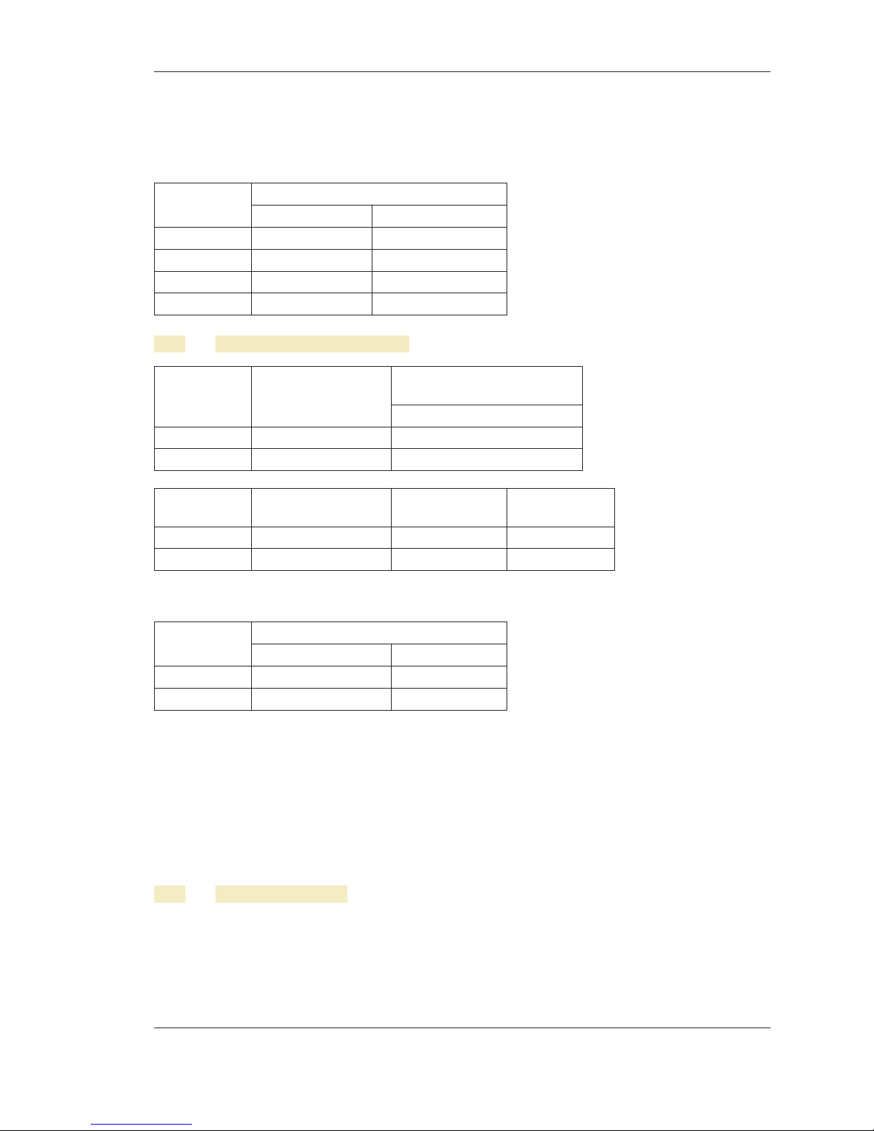
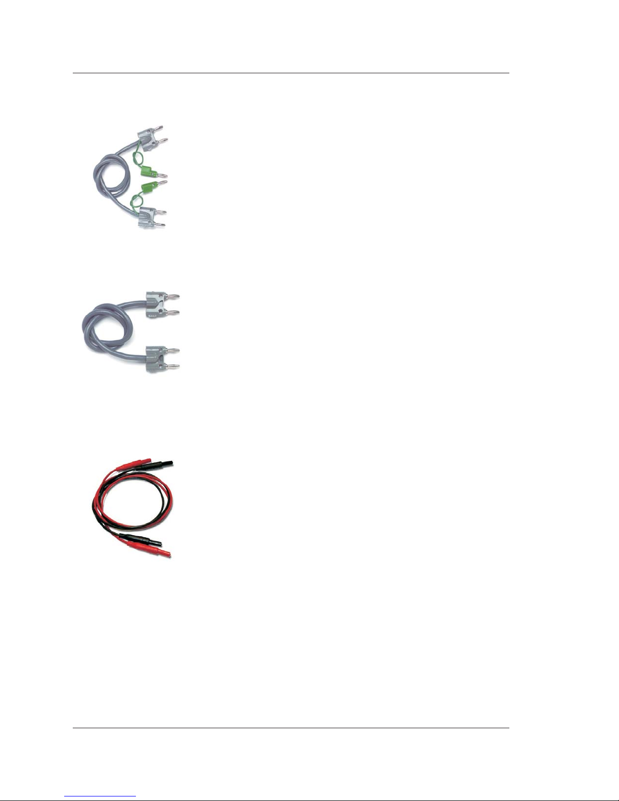
CAB-023: Cable Set, Low Thermal EMF Retractable Banana. The CAB023 is a low thermal EMF retractable
sheath banana plug patch cord set. These low thermal cables minimize thermal errors so accurate low voltage
measurements can be made. Each set includes 2 test leads (one black and one red).
1-6

Section 1 - General Description and Specifications
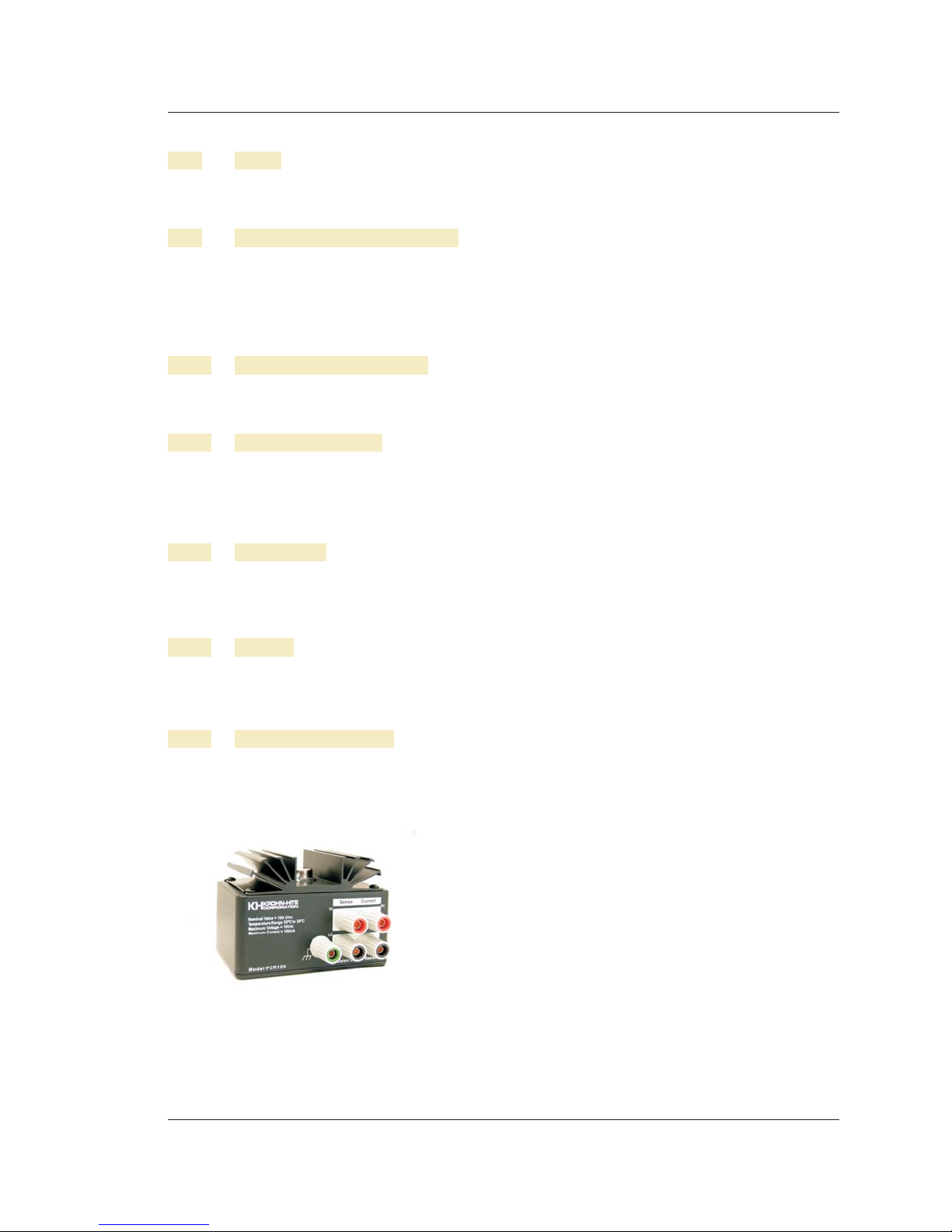
CAB-024: Cable set, low thermal EMF spade lug. The CAB024 is a low thermal EMF spade lug patch cord
set for low voltage measurements. These low thermal cables minimize thermal errors so accurate low voltage
measurements can be made. Each set includes 2 test leads (one black and one red).
CON13/15: 6-pin Amphenol military style output connector, clamp supplied.
Case-2720B: Carrying Case
Specifications are subject to change without notice.
1-7

Section 1 - General Description and Specifications
NOTES
_____________________________________________________________________________
_____________________________________________________________________________
_____________________________________________________________________________
_____________________________________________________________________________
_____________________________________________________________________________
_____________________________________________________________________________
_____________________________________________________________________________
_____________________________________________________________________________
_____________________________________________________________________________
_____________________________________________________________________________
_____________________________________________________________________________
_____________________________________________________________________________
_____________________________________________________________________________
_____________________________________________________________________________
_____________________________________________________________________________
_____________________________________________________________________________
_____________________________________________________________________________
_____________________________________________________________________________
_____________________________________________________________________________
_____________________________________________________________________________
_____________________________________________________________________________
_____________________________________________________________________________
_____________________________________________________________________________
_____________________________________________________________________________
_____________________________________________________________________________
_____________________________________________________________________________
1-8
Section 2 - Operation
SECTION 2
OPERATION
2.1 Introduction
NOTE: CAPITALIZED names represent the display area and Selector knob. A [BRACKET] signifies keys.
The Model 526 Precision DC Voltage/Current Source/Calibrator is a highly stable and repeatable DC voltage
and DC current source providing N.I.S.T. traceable voltages and currents for use in production, calibration
labs, QA and QC departments, design labs, or any place where an accurate voltage and current source is
needed. This section will describe each control and function of the Model 526.
WARNING
The 526 Source/Calibrator can supply lethal voltages. To avoid shock
hazard, read this section before operating the unit.
2.2 Selecting Line Voltage
The 526 operates from a line voltage of 105 to 130 or 210 to 260 volts ac, single phase, 50Hz/60Hz, 60 watts
max. The following paragraphs explain how to change the voltage settings and the fuse.
CAUTION
To avoid shock hazard, connect the factory supplied three conductor line power cord to
a properly grounded power outlet. Do not use a two-conductor adapter or extension
cord; this will break the protective ground connection. Use the rear-panel CHASSIS
GROUND terminal for a protective grounding wire if there is any question about the
effectiveness of instrument earth grounding through the power line cord ground wire.
The cover of the Power Entry Module shows four possible voltage settings (100V, 120V, 230V or 240V).
Notice that a pin will be in one of these holes, indicating the present voltage setting for the 526. The 526 will
NOT operate with voltages than those indicated in the table below.
AC Mains Pin
105V - 130V 100V or 120V
210V - 260V 230V or 240V
2-1
Section 2 - Operation
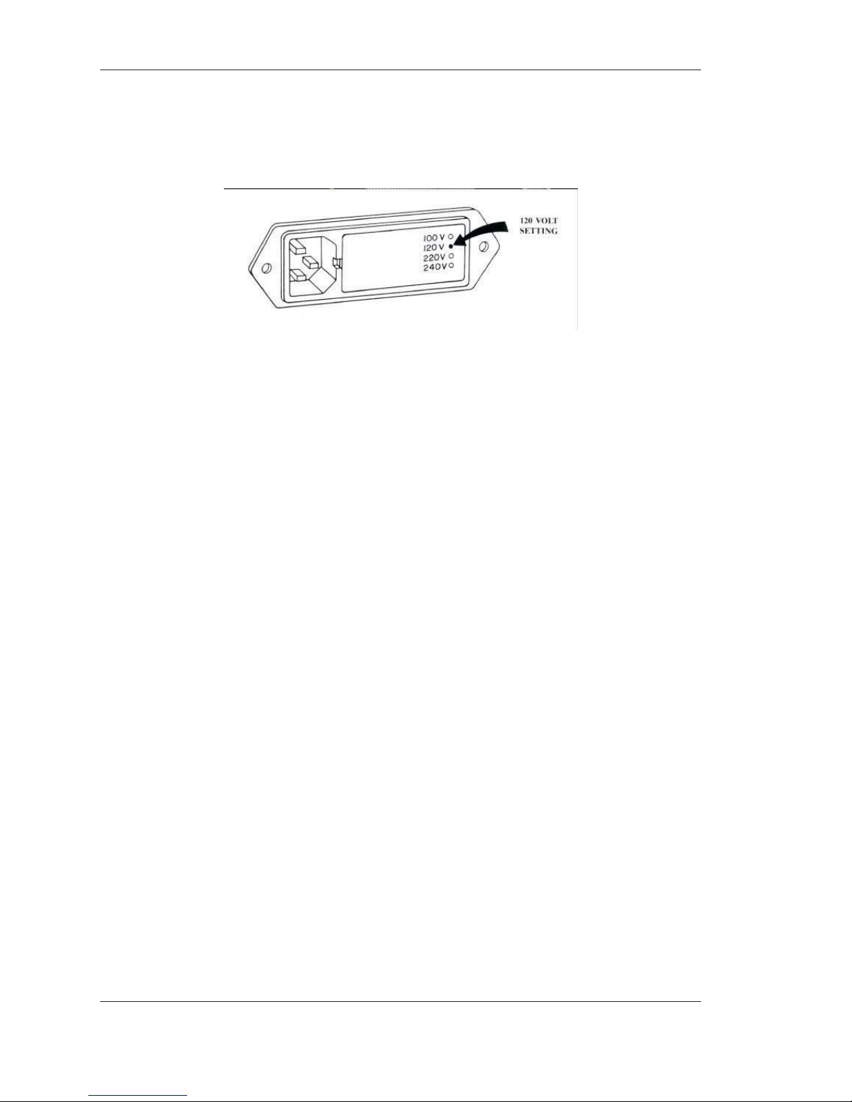
If this setting does not match the voltage available at your site, then it must be changed before powering on the
526. Figure 2.1 shows an example setting for 120 Vac operation.
Figure 2.1 Example 120V Setting
Follow the steps below to change a fuse or convert the operating voltage of a 526.
1. Set the 526 power switch to OFF.
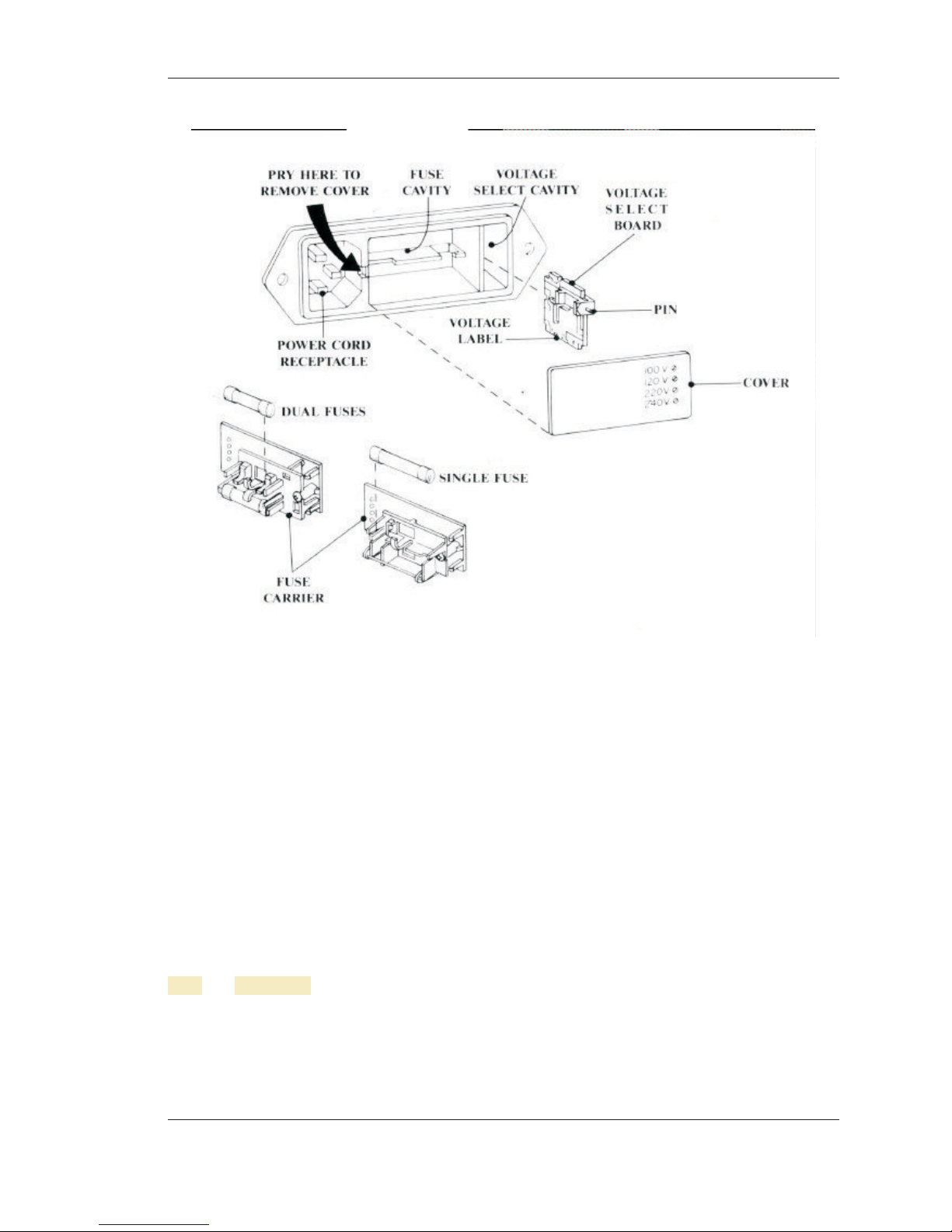
2. Unplug the power cord from the ac wall outlet and from the power cord receptacle on the power entry
module. See Figure 2.2.
3. Using a small flat blade screwdriver or similar tool inserted into the slot at the left edge of the cover,
carefully pry the cover off the fuse cavity.
4. To change the voltage setting, grasp the white plastic voltage select board pin and pull straight outward
until the voltage select board unseats from the power entry module. Hold the board so that you can read
the four voltage selection labels (100, 120, 230 and 240) imprinted on the board. Move the voltage
indicator pin to the opposite side of the board from the desired voltage label. Be sure to seat the pin in the
notch provided on the board’s edge. Install the voltage select board so that it is fully seated in the voltage
select cavity (the label side toward the fuse cavity).
5. To change the fuse (s), remove the fuse (s) from the fuse carrier on the back of the cover. For 100 or 120
Vac operation, the fuse rating is ¾ Amp, Slo-Blo. For 230 or 240 Vac operation, the fuse rating is 3/8
Amp, Slo-Blo. Be sure to use the correct rating for your voltage selection. For installation, insert the
fuse(s) of the proper rating into the fuse carrier.
6. To change the fuse arrangement to match that used in your country, remove the screw from the fuse
carrier, remove the fuse carrier, turn the fuse carrier so that the desired fuse arrangement (single fuse or
dual fuses) is facing outward, installthe fuse carrier, and install the screw. For United States type power
operation, use a single standard AGC or 3AG 0.25 inch x 1.25 inches fuse of the correct rating. For
European type power operation, use two standard 5.2 mm x 20 mm fuses of the correct rating. For
European use, it is important to note that if your local electrical code does not allow a dual fuse
arrangement, then a dummy fuse must be installed in the lower fuse carrier. Otherwise, the 526 will not
operate.
7. Place the cover on the power entry module and press inward until it snaps into place. Verify that the
desired operating voltage is indicated with the voltage select board pin on the cover label.
8. Connect the power cord to the power entry module and wall outlet. The 526 is now ready to be operated
on the selected ac line voltage.
2-2
Section 2 - Operation
Figure 2.2 Power Entry Module
2.3 Placement and Rack Mounting
You may place the 526 on a bench top or mount it in a standard-width, 24-inch (61-cm) deep equipment rack.
For bench-top use, the 526 is equipped with non-slipping, tilt, non-marring feet. To mount the 526 in an
equipment rack, use the Rack Mount Kit, Model RK-314.
2.4 Quick Start
After the 526 has been unboxed and set to the proper line voltage setting, the unit is ready to turn on. Plug the
526 into the power source and turn on.
The first time turned on, the 526 will display the factory default settings. The OUTPUT display should
indicate "ACTIVE". If not, press the [CROWBAR] key. Now turn the decade knobs to the desired voltage.
NOTE: When the 523's Power-On setting is set for LAST LCL SETTING, the output terminals will be
crowbarred. Press the [CROWBAR] key to activate output terminals after power-on.
2.4.1 526 Tones
The 526 has a tone generator that beeps when an entry has been made, a non-active key was pressed, or an
entry that was to exceed a limit was attempted. The short beep means the entry was correct. A long beep
indicates the attempted entry was already selected or incorrect.
2-3
Section 2 - Operation
2.4.2 LOCAL Key
Pressing the [LOCAL] key will always return the 526 to the last local setting, whether it be from remote
operation or from within a MENU FUNCTION.
2.4.3 SELECTOR Knob
The SELECTOR knob control is used to select a memory location for recalling or storing front panel set-ups;
or is used to select/set items from within the MENU Mode. It is always active in the LCL Mode for selecting
memory locations. The memory location viewed does not become active at the output terminals until
[RECALL] and [UPDATE OUTPUT] is pressed.
2.4.4 Setting a Voltage/Current
To set a voltage or current, do the following in LCL mode.
1. Check if LCL is displayed in the MODE display. If not, press [LOCAL]
2. Press the [V/mA] key to set the desired FUNCTION of voltage or current.
When pressed, the OUTPUT SETTING display indicates mV or mA and the OUTPUT
display indicates CROWBAR. This is done to protect the unit under test (UUT), that may be connected
to the 526, from damage.
3. Press [+/-] key to select positive or negative voltages/currents.
4. To set the desired range press [DOWN] or [UP] RANGE keys.
The LED's between the 3 MSD decades are decimal place indicators (see para 2.4.5).
NOTE: When changing the range from a higher range to a lower range and the voltage/current
exceeds the maximum limit for the new range, the 526 sets the voltage/current to the maximum
limit for the new range. If you change to a higher range, the 526 will maintains the same voltage from the
previous or lower range.
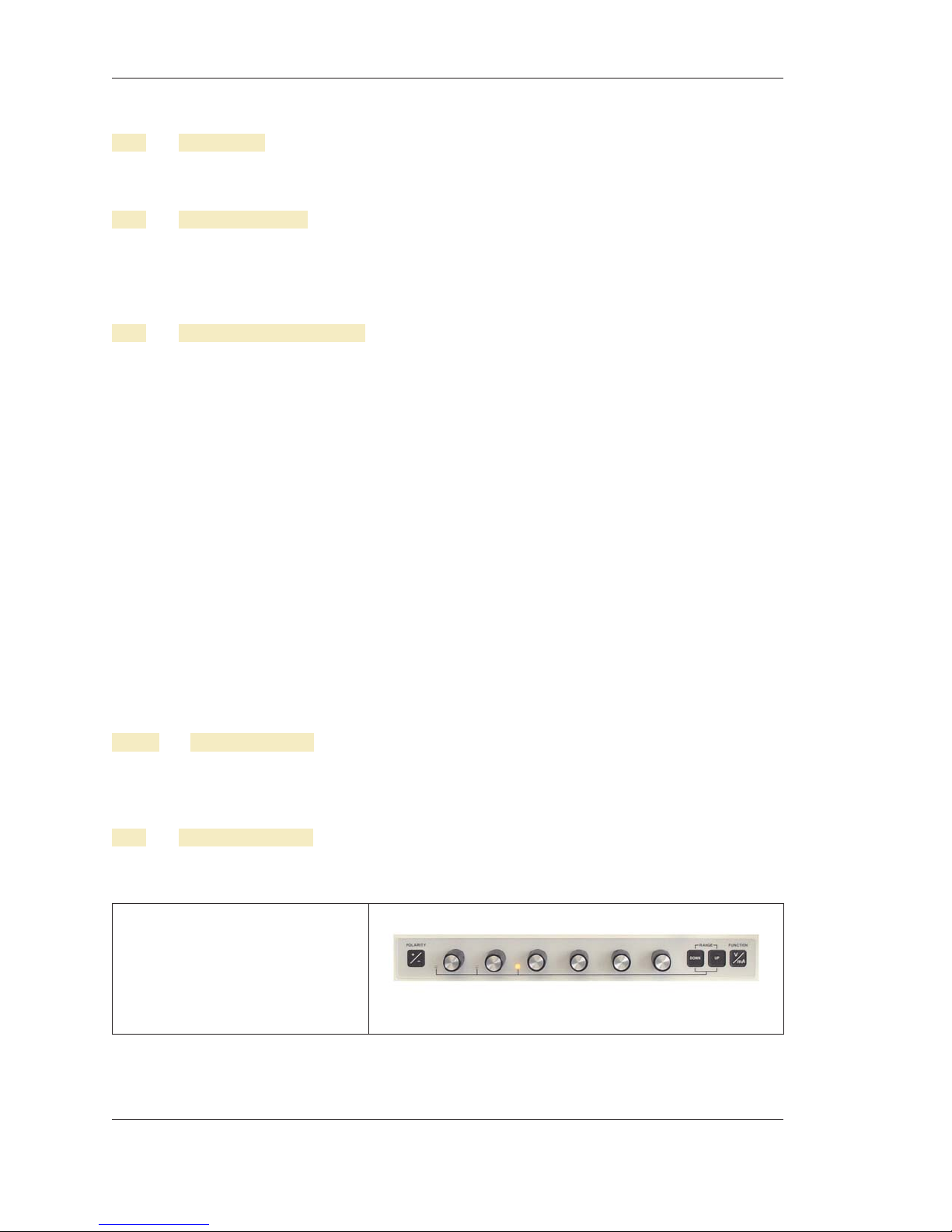
5. Turn the decade controls, below the display, to set the desired voltage/current.
6. Press [CROWBAR] to activate the output terminals. The OUTPUT display now indicates ACTIVE.
2.4.4.1 Decade Controls
Six microprocessor assisted decade controls provide continual use of any one decade with full carry and
borrow capability to and from all more significant decades for easier use and convenient manual operation.
Decade controls will only function when setting a voltage or current.
2.4.5 Selecting a Range
To set the desired range press [DOWN] or [UP] RANGE keys. The LED's between the 3 MSD decades are
decimal place indicators. Below is a chart showing each range LED.
Indicates 100mV, 100V or 100mA
Range is set.
OUTPUT SETTING display will
indicate either XX.XXXXmV,
XX.XXXXV or X.XXXXmA.
2-4
 Loading...