

Krohn-Hite 523 Operating Manual
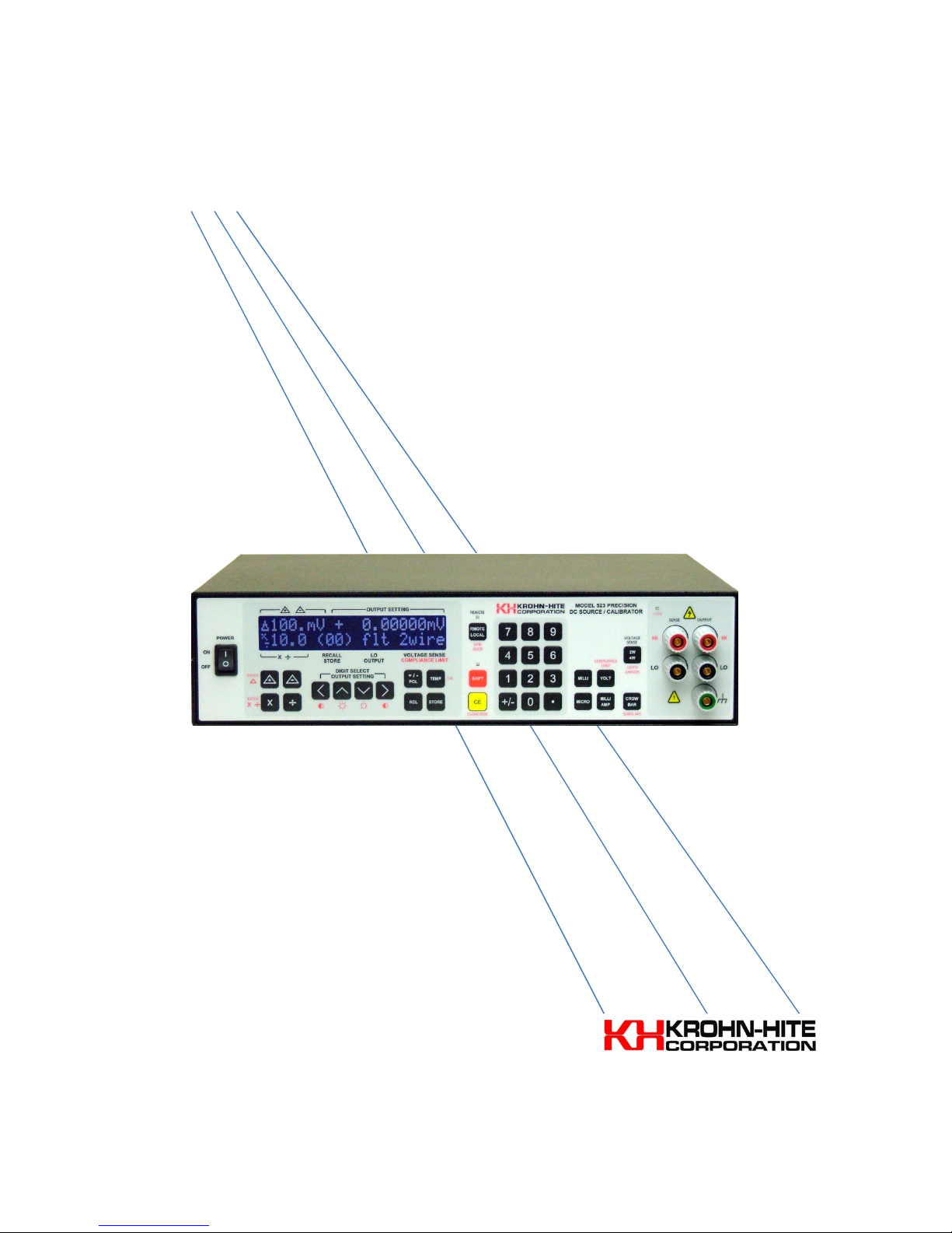
Model 523
GPIB Remote Controlled
Precision DC Source/Calibrator
Operating Manual

Service and Warranty
Krohn-Hite Instruments are designed and manufactured in accordance with sound engineering practices and
should give long trouble-free service under normal operating conditions. If your instrument fails to provide
satisfactory service and you are unable to locate the source of trouble, contact our Service Department at
(508) 580-1660, giving all the information available concerning the failure.
DO NOT return the instrument without our written or verbal authorization. When contacting us, we will
issue a Return Authorization Number that should be referenced on the packing slip and purchase order. In
most cases, we will be able to supply you with the information necessary to repair the instrument, avoiding
any transportation problems and costs. When it becomes necessary to return the instrument to the factory,
kindly pack the instrument carefully and ship it to us prepaid.
All Krohn-Hite products are warranted against defective materials and workmanship. This warranty applies
for a period of one year from the date of delivery, to the Original Purchaser. Any instrument that is found
within the one-year warranty period not to meet these standards will be repaired or replaced. This warranty
does not apply to fuses or batteries. No other warranty is expressed or implied.
Krohn-Hite Corporation reserves the right to make design changes at any time without incurring any
obligation to incorporate these changes in instruments previously purchased. Modifications to this
instrument must not be made without the written consent of an authorized employee of Krohn-Hite
Corporation.
CLAIMS
Immediately upon arrival, purchaser shall check the packing container against the enclosed packing list and
shall, within thirty days of arrival, give Krohn-Hite notice of shortages or any non-conformity with the terms
of the order.
The purchaser assumes all risk of loss or damage to instrument upon delivery by Krohn-Hite to the carrier. If
an instrument is damaged in transit, purchaser must file all claims for damage with the carrier to obtain
compensation. Upon request by purchaser, Krohn-Hite will submit an estimate of cost to repair shipment
damage.

Model 523 DC Source/Calibrator
_________________________________________________________________________________
Model 523
Precision DC Source/Calibrator
Operating Manual
Revision 4.1. Printed in U.S.A. 10/2013
Model 523Rev4.docx
Copyright 2013
All rights reserved. Contents of this publication may not be reproduced
in any form without the written permission of Krohn-Hite Corporation.
15 Jonathan Drive, Unit 4, Brockton, MA 02301-5566
Tel: (508) 580-1660; Fax: (508) 583-8989
sales@Krohn-hite.com; www.krohn-hite.com
[i]

Model 523 DC Source/Calibrator
_________________________________________________________________________________
Table of Contents
MODEL 523 .................................................................................................................................................................... I
GPIB R
EMOTE CONTROLLED
P
RECISION DC SOURCE/CALIBRATOR
SERVICE AND WARRANTY ............................................................................................................................................. II
....................................................................................................................................................
.........................................................................................................................................
CLAIMS ............................................................................................................................................................ II
SAFETY ISSUES .............................................................................................................................................................. V
WARNING .........................................................................................................................................................................
POWER SOURCE ...............................................................................................................................................................
PROPER FUSE....................................................................................................................................................................
GROUND THE INSTRUMENT .............................................................................................................................................
PROTECTIVE EARTH GROUND ..........................................................................................................................................
DO NOT OPERATE IN AN EXPLOSIVE AREA ......................................................................................................................
KEEP AWAY FROM LIVE CIRCUITS ....................................................................................................................................
DO NOT SUBSTITUTE PARTS OR MODIFY INSTRUMENT ..................................................................................................
DO NOT OPERATE A DAMAGED INSTRUMENT ................................................................................................................
DO NOT REMOVE COVER .................................................................................................................................................
UNPACKING AND INSPECTION ........................................................................................................................................
SECTION 1 – GENERAL DESCRIPTION AND SPECIFICATIONS .......................................................................................... 1
1.1 INTRODUCTION ...................................................................................................................................................... 1
1.2 AUTO ZERO OFFSET ................................................................................................................................................ 1
1.3 STORING OUTPUT SETTINGS ................................................................................................................................... 1
1.4 APPLICATIONS ........................................................................................................................................................ 1
1.5 CALIBRATION PROCESS ........................................................................................................................................... 2
1.6 SUPPORT EQUIPMENT NEEDED .............................................................................................................................. 2
1.7 ESTABLISHING TRACEABILITY ................................................................................................................................. 2
1.8 CALIBRATION REPORTS ........................................................................................................................................... 2
1.9 CALIBRATION CHECK ............................................................................................................................................... 2
1.10 CALIBRATION INTERVALS ................................................................................................................................... 2
1.11 TEMPERATURE CONTROL .................................................................................................................................. 2
1.12 SPECIFICATIONS ................................................................................................................................................. 3
1.12.1 Output Specifications (Specifications apply at CAL TEMP ±1ºC, <70% relative humidity.) ......................... 3
1.12.2 GPIB Programming ....................................................................................................................................... 5
1.12.3 Terminals ..................................................................................................................................................... 5
1.12.4 General ........................................................................................................................................................ 5
1.12.5 Safety ........................................................................................................................................................... 5
1.12.6 Electromagnetic Compatability ................................................................................................................... 5
1.12.7 Options ........................................................................................................................................................ 5
1.12.8 Optional Accessories .................................................................................................................................... 6
1.12.9 Accessories .................................................................................................................................................. 7
I
I
V
V
V
V
V
VI
VI
VI
VI
VI
VI
SECTION 2 - OPERATION ............................................................................................................................................... 9
2.1 QUICK START AND TURN-ON PROCEDURE.............................................................................................................. 9
2.1.1 Voltage Selection ......................................................................................................................................... 9
2.1.2 Fuse Installation Instructions ..................................................................................................................... 10
2.2 FRONT PANEL CONTROLS ..................................................................................................................................... 11
2.2.1 Basics Entry Characteristics ....................................................................................................................... 11
[ii]

Model 523 DC Source/Calibrator
_________________________________________________________________________________
2.2.2 Tone Annunciator ...................................................................................................................................... 11
2.2.3 Leading and Trailing Zeros ......................................................................................................................... 11
2.2.4 >15 Volt Indicator ...................................................................................................................................... 12
2.2.5 Shift Key ..................................................................................................................................................... 12
2.2.6 Remote/Local Key ...................................................................................................................................... 12
2.2.7 Clear Entry Key........................................................................................................................................... 13
2.2.8 Setting the GPIB Address ........................................................................................................................... 13
2.2.9 Crowbar Key .............................................................................................................................................. 14
2.2.10 Voltage Key ................................................................................................................................................ 14
2.2.11 Current Key ................................................................................................................................................ 15
2.2.12 Compliance Limits ...................................................................................................................................... 16
2.2.13 2-Wire/4-Wire Key (Output Termination) ................................................................................................. 17
2.2.14 Lo To Chassis Key (flt/chs) ......................................................................................................................... 17
2.2.15 Delta Key (ENTER ∆ ) .................................................................................................................................. 17
2.2.16 Multiply/Divide Key (ENTER × ÷) ............................................................................................................... 18
2.2.17 +/– Polarity Key ......................................................................................................................................... 19
2.2.18 Store/Recall Key ......................................................................................................................................... 19
2.2.19 Temp Key ................................................................................................................................................... 20
2.2.20 CAL Key ...................................................................................................................................................... 20
2.2.21 Clear Mem Key........................................................................................................................................... 21
2.2.22 Serial No. ................................................................................................................................................... 21
2.2.23 Digit Select and Controls ........................................................................................................................... 21
2.2.24 Display Brightness and Contrast Control ................................................................................................... 22
2.3 CONDITIONS THAT WILL PRODUCE AN ERROR MASSAGE .................................................................................... 22
2.3.1 Too High Entry of a Voltage or Current Level ............................................................................................ 22
2.3.2 Too High Entry of a Compliance Voltage Level .......................................................................................... 23
2.3.3 Too High Entry of a Delta Voltage Level .................................................................................................... 23
2.3.4 Output Limit Condition .............................................................................................................................. 23
2.3.5 Storing or Recalling Beyond the Maximum Location of 30. ...................................................................... 23
2.3.6 Recalling from a Location That Has No Stored Setup in It. ........................................................................ 24
2.3.7 Illegal GPIB Address Entry .......................................................................................................................... 24
2.4 OUTPUT CONNECTIONS ....................................................................................................................................... 24
2.4.1 Front and Rear Panel Terminals ................................................................................................................ 24
2.4.2 Wire and Cable Connections ..................................................................................................................... 25
2.4.3 Temperature Control ................................................................................................................................. 26
SECTION 3 - GPIB PROGRAMMING.............................................................................................................................. 27
3.1 I
NTRODUCTION
3.1.1 Setting the GPIB Address ........................................................................................................................... 28
3.1.2 GPIB Instruction Syntax ............................................................................................................................. 29
3.1.3 Crowbar ..................................................................................................................................................... 29
3.1.4 Voltage ....................................................................................................................................................... 29
3.1.5 Current ....................................................................................................................................................... 30
3.1.6 Compliance ................................................................................................................................................ 30
3.1.7 2 Wire/4 Wire Output Termination ........................................................................................................... 30
3.1.8 Lo Float/Chassis (flt/chs) ........................................................................................................................... 31
3.1.9 Delta ∆ ....................................................................................................................................................... 31
3.1.10 Multiply/Divide ×/÷.................................................................................................................................... 32
3.1.11 +/– Polarity ................................................................................................................................................ 32
3.1.12 Store/Recall ............................................................................................................................................... 33
3.2 T
OGGLE
3.3 SPECIAL COMMANDS ........................................................................................................................................... 33
3.3.1 Reset Command (*RST or *rst) .................................................................................................................. 34
3.3.2 Calibration Command (*CAL or *cal) ......................................................................................................... 34
............................................................................................................. E
................................................................................................................................................................... 33
[iii]
RROR! BOOKMARK NOT DEFINED
.

Model 523 DC Source/Calibrator
_________________________________________________________________________________
3.3.3 Full Calibration Command (523 *CAL or 523*cal) ..................................................................................... 34
3.3.4 Clear Memory Command (*CLM or *clm) ................................................................................................. 34
3.3.5 Identification Query Command (*IDN? Or *idn?) ..................................................................................... 34
3.3.6 String Query Command (*STG? or *stg?) .................................................................................................. 35
3.3.7 Last Calibration Date Query Command (*CLD? or *cld?) .......................................................................... 35
3.3.8 Temperature Query Command (*TMP? or *tmp?) ................................................................................... 35
3.3.9 Message Query Command (*MSG? or *msg?) .......................................................................................... 36
3.4 C
ONDITIONS THAT WILL PRODUCE A SERVICE REQUEST ON THE
3.4.1 Entry of a Voltage or Current Level Greater Than the Capabilities of the 523 .......................................... 36
3.4.2 Entry of a Compliance Voltage Level Greater than the Capabilities of the 523 ........................................ 36
3.4.3 Entry of too Large a Delta Voltage or Current Value. ................................................................................ 36
3.4.4 Entry of an Unrecognized Instruction or Command. ................................................................................. 36
3.4.5 Output Limit Condition .............................................................................................................................. 37
3.4.6 Storing or Recalling Beyond the Maximum Location of 30........................................................................ 37
3.4.7 Recalling from a Location That Has No Stored Setup ................................................................................ 37
3.4.8 Serial Poll Initial Response Byte Chart ....................................................................................................... 37
GPIB ................................................................................. 36
SECTION 4 - PERFORMANCE VERIFICATION ................................................................................................................ 39
4.1 INTRODUCTION .................................................................................................................................................... 39
4.2 TEMPERATURE CONTROL ..................................................................................................................................... 39
4.3 REQUIRED EQUIPMENT ........................................................................................................................................ 39
4.4 PRELIMINARY SET-UP ........................................................................................................................................... 39
4.5 INSPECTION PROCEDURE...................................................................................................................................... 40
4.5.1 Auto Zero Offset Calibration (AZOC) .......................................................................................................... 40
4.5.2 Output Voltage Checks .............................................................................................................................. 40
4.5.3 Output Current Checks (using PCR100 Precision Resistor) ........................................................................ 41
[iv]

Model 523 DC Source/Calibrator
_________________________________________________________________________________
SAFETY ISSUES
WARNING
HIGH VOLTAGE is used in the operation of this instrument. LETHAL voltages may be present on the output
terminals. Please observe all safety precautions when operating this instrument.
POWER SOURCE
The Model 523 is intended to operate from a 105V to 240V ac rms source. A protective ground connection
by way of the grounding conductor in the power cord is essential for safe operation.
PROPER FUSE
To avoid damage to the Model 523 or to prevent a fire hazard, use the correct fuse for the line voltage
selected. Proper fuse requirement is screened on the rear panel of the instrument above the power
connector.
The Model 523 has been designed, tested and supplied in a safe condition. The following general safety
precautions must be observed during all phases of operation, service, and repair. Failure to comply with
these precautions or with specific warnings elsewhere in this manual violates safety standards of design,
manufacture and intended use of this instrument. Krohn-Hite assumes no liability for the customer’s failure
to comply with these requirements.
This manual contains information and warnings that must be observed to keep the instrument in a safe
condition and ensure safe operation. Operation or service in conditions or in a manner other than specified
could compromise safety. For the correct and safe use of this instrument, operating and service personnel
must follow generally accepted safety procedures.
To avoid injury or fire hazard, do not switch on the instrument if it is damaged or suspected to be faulty. Do
not use the instrument in damp, wet, condensing, dusty or explosive gas environments.
Whenever it is likely that safety protection has been impaired, make the instrument inoperative and secure
against any unintended operation, and then inform qualified personnel. Safety protection is likely to be
impaired if, for example, the instrument shows visible damage, or fails to operate normally.
GROUND THE INSTRUMENT
To minimize shock hazard, the instrument chassis and cabinet must be connected to an electrical ground.
Any interruption of the protective ground conductor inside or outside the instrument is likely to make the
instrument dangerous. Intentional interruption is prohibited.
PROTECTIVE EARTH GROUND
Protective earth symbols located on the inside rear chassis near the AC line filter module designate the point
at which the safety earth system is attached to the chassis. These symbols must not be altered or removed.
The safety earth wires (green/yellow) must never be disconnected. The safety earth ground wires
green/yellow) connecting the module must make direct contact with the chassis.
The following are symbols used on the chassis of the 523:
[v]

Model 523 DC Source/Calibrator
_________________________________________________________________________________
---- Chassis Protective Ground
---- AC (Alternating Current)
---- Conforms to European Union Directives
---- Important Information, Refer to the Manual
---- Caution, Risk of Electric Shock
DO NOT OPERATE IN AN EXPLOSIVE AREA
Do not operate the instrument in the presence of flammable gases or fumes. Operation of any electrical
instrument in such an environment constitutes a definite safety hazard.
KEEP AWAY FROM LIVE CIRCUITS
Operating personnel must not remove instrument covers. Qualified maintenance personnel must make
component replacement and internal adjustments. Under certain conditions, dangerous voltages may exist.
To avoid injuries, always disconnect input voltages before removing the covers.
DO NOT SUBSTITUTE PARTS OR MODIFY INSTRUMENT
Because of the danger of introducing additional hazards, do not install substitute parts or perform any
unauthorized modifications. Return the unit to the Krohn-Hite Service Department to modify or repair the
instrument to ensure that safety features are maintained.
DO NOT OPERATE A DAMAGED INSTRUMENT
Whenever it is possible that the safety protection features built into this instrument have been impaired,
either through physical damage, excessive moisture, or any other reason, REMOVE the POWER and do not
use the instrument until safe operation can be verified by service-trained personnel. If necessary, return the
instrument to the Krohn-Hite Service Department for service and repair to ensure that the safety features
are maintained.
DO NOT REMOVE COVER
To avoid personal injury, do not remove the covers of the Model 523. There are no user-serviceable parts
inside the instrument, so there is no reason for any user to remove the covers of this instrument.
UNPACKING AND INSPECTION
The Model 523 has been shipped in a container designed to prevent any damage from occurring during
shipping. Inspect the 523 carefully for damage, and immediately report any damage to the shipper.
If you need to return the 523 for any reason, use the original container if possible. If not, you can order a
new container from Krohn-Hite Corporation at (508) 580-1660 indicating the model and serial number.
[vi]

Model 523 DC Source/Calibrator
_________________________________________________________________________________
SECTION 1
General Description and Specifications
1.1 INTRODUCTION
The Krohn-Hite Model 523 Precision DC Source is a highly stable and repeatable dc voltage and current
source providing N.I.S.T. traceable voltages and currents for use in production, calibration labs, QA and QC
departments, design labs, or any place where an accurate voltage or current source is needed.
Using Krohn-Hite’s state-of-the-art reference, the 523 provides accurate and stable voltages to
±110.99999Vdc to within ±4ppm for 90 days (±8ppm for 1 year), and precise currents to ±110.99999mA to
within ±8ppm for 90 days (±16ppm for 1 year). It is an extremely quiet source with <7μVrms of noise
measured over a 10Hz to 100kHz bandwidth (<2μVrms 0.1Hz to 10Hz).
The 523 features a user friendly 7½ digit display and a membrane keyboard entry for all settings. Output
settings can be modified using a plus/minus delta function, multiply/divide function and cursor control keys
that allow placing a curse on any digit to increment or decrement its value. Output 2-wire, 4-wire and
chassis grounding are accomplished with one keystroke. A crowbar function places the output in a safe
mode when desired. The 523 output can be set to 0 volts, allowing the output sense to maintain true 4-wire
low impedance zero output.
1.2 AUTO ZERO OFFSET
An AUTO ZERO OFFSET CALIBRATION (AZOC) corrects any thermally generated offsets to within specified
limits and is accessible via the front panel or over the GPIB interface bus. The unit is designed for a “CoversOn Calibration” using the KH523CAL Automatic Testing and Calibration Program (a license is required for
calibration only). With the KH523CAL software program and a Model HP3458 or Fluke 8508A Digital
Voltmeter, unattended calibrations can be made in approximately 15 minutes.
1.3 STORING OUTPUT SETTINGS
The 523 provides for the storage of up to 31 output settings that can be recalled at any time. Internal
operating temperature, serial number, last calibration date and firmware version can all be called to the
display for quick access when needed. Error messages are displayed when incorrect or out-of-range entries
are made.
1.4 APPLICATIONS
The Model 523 is well suited for many applications where an extremely accurate and stable dc voltage or dc
current is needed. At a cost much less than most sources in its class, the 523 can be a valuable asset to any
company’s production line, calibration lab, QA and QC department and design lab.
[1]

Model 523 DC Source/Calibrator
_________________________________________________________________________________
1.5 CALIBRATION PROCESS
Calibration of the Model 523 requires the HP3458A or Fluke 8508A Digital Multimeter and a precision 100
ohm resistor (optional Krohn-Hite Model PCR100). Calibration constants that define the calibration points
for controlling the output are stored in memory. Traceable calibration to the specified performance is
accomplished in a semi-automated process that updates this table during calibration using the KH523CAL
Automatic Testing and Calibration Program.
1.6 SUPPORT EQUIPMENT NEEDED
The only support equipment needed for the Model 523 is the HP3458A or Fluke 8508A Digital Multimeter
and a precision 100 ohm resistor (optional Krohn-Hite Model PCR100) for current adjustment checks.
1.7 KROHN-HITE TRACEABILITY
Traceability to national standards is accomplished as follows:
Have a traceable to N.I.S.T. (National Institute of Standards and Technologies) HP3458A that is periodically
checked against an in-house Fluke 732A, 10V Reference. All verifications of calibration must be performed to
better than actual manufacturers specifications.
1.8 CALIBRATION REPORTS
In the future the KHCAL523 Automatic Testing and Calibration Program, provided with each unit, will have
the ability to display and print N.I.S.T. traceable reports.
1.9 CALIBRATION CHECK
Checking the calibration of the Model 523 can be simply accomplished using the KHCAL523 Automatic
Testing and Calibration Program. The program allows for two calibration tests, a voltage only and current
only test. The voltage test checks 90 points while the current test checks 46.
1.10 CALIBRATION INTERVALS
The traditional practice of returning a calibrator to a standards laboratory at regular intervals for a full
calibration is disruptive, costly and time consuming. It can leave a gap in confidence. You then rely on
manufacturer’s specifications to determine if a calibrator will perform the same outside the lab. So you then
must assume that drift is predictable enough so that the performance is within limits between recalibrations.
However, the Model 523 can be completely calibrated to its original specifications by using a HP3485A
Multimeter, a 100 ohm standard precision resistor and the Krohn-Hite optional KHCAL523 Testing and
Calibration Program, and by not removing its covers or making an adjustment.
1.11 TEMPERATURE CONTROL
To maximize performance in the Model 523, the internal temperatures must be controlled. The 523 has
internal temperature control by the use of a temperature sensor. The 523 can maintain 40°C ±0.1º if
operated in a favorable environment. A favorable environment is one that is maintained between 20°C to
28°C (68°F to 82.4°F) with average temperature changes not occurring faster than 1ºC per hour
(approximately 2°F per hour).
[2]

Model 523 DC Source/Calibrator
_________________________________________________________________________________
The top cover of the 523 should not be directly exposed to airflow from a heat or air conditioning register,
or air circulating fan. For peak performance when the 523 is moved to a new location, allow the 523 to
acclimate to its environment for 4 to 8 hours. If a room temperature transient should occur, allow 1 to 4
hours for the 523 to correct out the effect. If the 523 has been off for an extended period of time, allow 8
hours for the internal temperatures to stabilize and achieve maximum performance. For short periods, allow
1 to 4 hours. When first making connection to the 523 and other devices, allow temperatures generated
thermals at the terminals to stabilize for a minute or two. This is important for μV level effects.
Following these recommendations will maximize the 523 capabilities and are good practices for any ultraprecision instrument.
1.12 SPECIFICATIONS
The following specifications are with a constant internal operating temperature equal to Calibration
Temperature (Cal Temp) ±1°C. The HP3458A NPLC is set for 100 and AUTO CAL cycle (ACAL) run. The Model
523’s calibration is normally done at a room temperature of 23°C ±1°C. The internal Cal Temp is saved at the
time of calibration and is displayed with the present internal temperature using the [TEMP] key.
The 90 day and 1 year specifications are valid within 24 hours of a zero CAL (AZOC) cycle, and a constant
internal operating temperature equal to the Calibration Temperature (Cal Temp) ±1°C. The zero CAL (AZOC)
cycle takes out the effect of internal DC offset drift.
1.12.1 Output Specifications (Specifications apply at CAL TEMP ±1ºC, <70% relative humidity.)
Relative 1
Uncertainty
±1°C
90
days
1yr 24 hrs 90 days 1yr 24 hrs
Range Res.
DC Voltage
111.11119mV
1.1111119V
11.111119V
110.99999V
DC Current 3
11.111119mA
110.99999mA**
* Non-Additive
** For values between 12mA and 110mA use graph provided with PCR100 Precision Resistor.
10nV
100nV
1μV
10μV
1nA
10nA
4 + 2
4 + 3
4 + 20
6 + 200
8 + 40
8 + 200
8 + 2
8 + 3
8 + 20
10 +200
16 + 40
16 + 200
3 + 2
3 + 2
3 + 10
5 +100
4 + 20
±24, +400
Absolute Uncertainty2 ±1°C from
calibration temperature
±(ppm output + μV or nA)
6 + 2
6 + 3
6 + 20
8 + 200
10 + 40
±30, +400
10 + 2
10 + 3
10 + 20
12 + 200
18 + 40
±38, +400
• Note 1: The RELATIVE ACCURACY specifications are to the HP3458A Digital Voltmeter used for
calibration.
• Note 2: The absolute accuracies and traceability to N.I.S.T. include the traceability accuracies of the
calibration standard and the maintained RELATIVE accuracies of the HP3458A or Fluke 8508A
added to the 523 RELATIVE specifications.
• Note 3: Current calibration uses an external precision 100-ohm resistor (Krohn-Hite Model PCR100) and
measures the voltage using a 4-wire Kelvin connection to the resistor.
Stability
*
±1°C
1 + 1
1 + 1
1 + 10
1 + 100
2 + 20
2 + 100
[3]
Model 523 DC Source/Calibrator
Temperature Coefficient
Noise
DC Voltage
111.1119mV
1 + 0.2
2 + 0.2
1 + 1
2μV
7μV
0.1μ
DC Current
11.111119
mA
2 + 5
4 + 5
1 + 20
20nA
150nA
10G
Temperature coefficient is best straight line fit method.
* Non
-
Additive
_________________________________________________________________________________
18°C
to
28°C
Range
1.1111119mV
11.111119mV
110.99999V
110.99999mA
Settling Time: <10ms.
Line Regulation: <±0.1ppm change for a 10% change from normal line voltage, typically no measurable
change.
Load Regulation 4-Wire Operation: <±0.1ppm change from no load to 100mA full load, typically no
measurable change. Measurements must be made at sense lead connection point to the load.
Compliance Voltage Effect on Current Output: <10nA change for a 100V change in compliance voltage for
output currents <11.11112mA, equivalent to >10 Gig-ohm output impedance; <100nA change for a 100V
change in compliance voltage for output currents ≥11.11112mA, equivalent to >1 Gig-ohm output
impedance.
±(ppm output + μV or nA)/°C
1 + 0.5
1 + 1
2 + 10
2 + 10
0°C - 18°C
28°C - 40°C
2 + 0.5
2 + 1
4 + 10
4 + 10
Linearity *
±1°C
1 + 1
1 + 10
1 + 100
1 + 100
0.1Hz
to
10Hz
p-p rms
2μV
4μV
40μV
200nA
10Hz
to
100kHz
7μV
15μV
100μV
300nA
Equivalent
Output Zo
(ohms)
1μ
10μ
100μ
1G
Compliance Voltage Limit: Settable in 1V steps from 1V to 110V. Compliance limits approximately 15%
+0.25V above the setting.
Compliance Voltage Limit: Settable in 1V steps from 1V to 110V. Compliance limits approximately 15%
+0.25V above the setting.
Maximum Output Current: ±110mA. Output protected from damage with a current limiter. Output may be
shorted to ground indefinitely.
Warm-Up Time from a Cold Start: 1 Hour to within 5ppm of final value. 4 Hours to rated accuracy and final
value.
Calibration: The Model 523 is specified with a 1-year calibration cycle. An AUTO ZERO OFFSET CALIBRATION
(AZOC) is provided that returns any thermally generated offset to within specified limits, and can be
accessed via front panel controls or over the GPIB interface bus. The Model 523 is designed for a “Covers
On” calibration using the KH523CAL Test and Calibration Software Program. The KH523CAL software,
together with an HP3458A or Fluke 8508A Digital Voltmeter, allows virtually unattended calibration to be
performed in approximately 15 minutes. The calibration date and internal temperature is stored in memory
and can be called to the display or over the GPIB interface bus. Calibration Temperature Limits (“Covers-On
Calibration”): Internal temperature (T Cal), 40°C ±1°C; Ambient temperature (T Amb), 0°C to 30°C.
Isolation: Floated up to 100Vdc with respect chassis ground. Power transformer-to-analog output, control
logic-to-analog output, optically isolated.
[4]

Model 523 DC Source/Calibrator
_________________________________________________________________________________
1.12.2 GPIB Programming
Switching Time: Typically 300ms.
Subsets: SH1, AH1, T6, SR1, RL1, PP1, DC1, DC1, DT1, CO, E1.
Line Termination: The GPIB EOI signal is always sent with the last character on a line.
Talker Function: Allows interrogation of the Model 523 by a controller.
1.12.3 Terminals
Output Terminals: Gold plated mounted on both the front and rear panels. Only one set of terminals may
be used at a time. Both terminal sets are configured for remote sensing of the output as follows:
High Output and High Sense
Low Output and Low Sense
Case Ground.
1.12.4 General
Display: 2 line, 40 character, backlit, LCD, 7½ digits. Displays output settings and other pertinent
information.
Keyboard: Membrane. Mechanical
Power Requirements: Selectable 105-130 or 210-240 volts ac, single phase, 50Hz to 60Hz, 60 watts.
Dimensions and Weights: 3.5“ (9cm) high, 14" (36cm) wide, 12.5” (32.13cm) deep; 12 lbs (5.4kg) net, 14 lbs
(6.3kg) shipping.
Operating Temperature Range: 0ºC to 50ºC.
1.12.5 Safety
The Model 523 is designed to meet the requirements of the following standards of safety for electrical
equipment for measurement, control and laboratory use: IEC61010-1, EN61010-1.
1.12.6 Electromagnetic Compatibility
Emissions and Immunity: EN61326-1, EMC, 61000-4-2; ESD, 61000-4-3; Radiated Immunity, 61000-4-4; EFT,
61000-4-5; Surge, 61000-4-6; Conducted Immunity, 61000-4-8; Magnetic Immunity, 61000-4-11; Voltage
Interruption EN61010-1. CE Compliant for Class B Equipment.
1.12.7 Options
RK-314: Rack Mount Kit, added brackets for the installation of the Model 523 into 19” rack spacing.
Figure 1.1 – RK-314 Rack Mount Kit
523-10: Voltage Limit, limits the output to a predefined value between 17Vdc to 100Vdc.
KH523CAL Software Calibration Program: Required to calibrate the Model 523 using an HP3458A or Fluke
8508A and a PCR100 Krohn-Hite Precision 100 Ohm Resistor.
[5]
Model 523 DC Source/Calibrator
_________________________________________________________________________________
1.12.8 Optional Accessories
CAB005: Cable, 2 conductor shielded balanced line.
Figure 1.2 – CAB-005 Shielded Balanced Line Cable
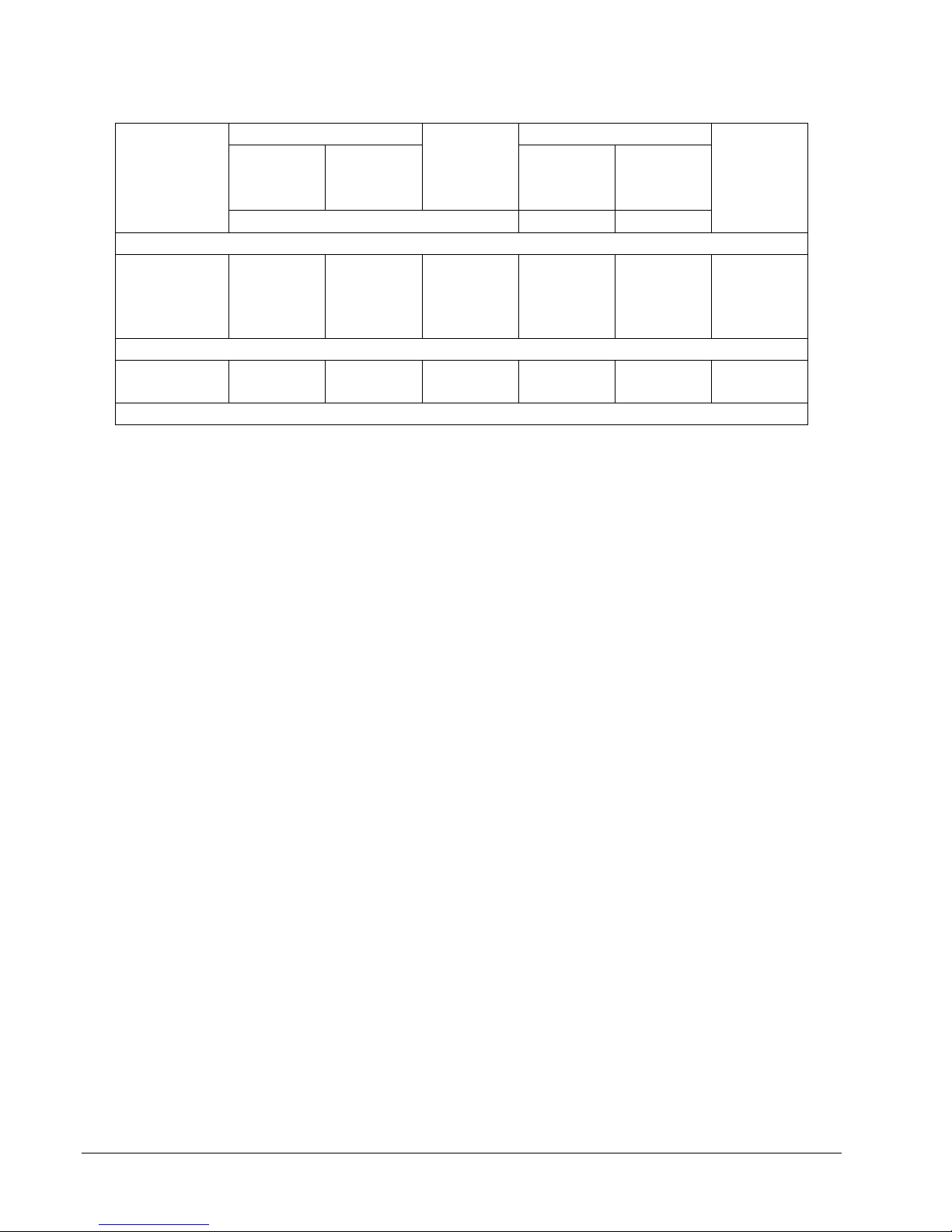
CAB018: Cable: multi-stacking double banana plug.
Figure 1.3 – CAB-018 Double Banana Plug Cable
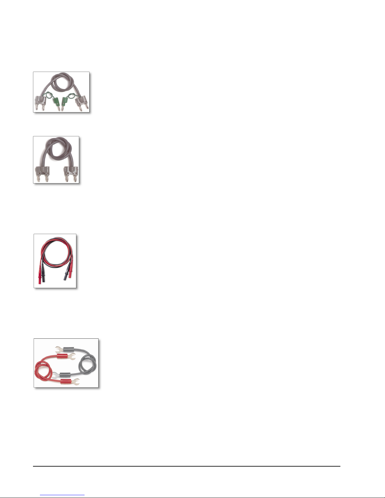
CAB023: The CAB023 is a low thermal EMF retractable sheath banana plug patch cord set. These low
thermal cables minimize thermal errors so accurate low voltage measurements can be made. Each set
includes 2 test leads (one black and one red).
Figure 1.4 – CAB-023 Banana Plug Patch Cord
CAB024: The CAB024 is a low thermal EMF spade lug patch cord set for low voltage measurements. These
low thermal cables minimize thermal errors so accurate low voltage measurements can be made. Each set
includes 2 test leads (one black and one red).
Figure 1.5 – CAB-024 Spade Lug Patch Cord
[6]
Model 523 DC Source/Calibrator
_________________________________________________________________________________
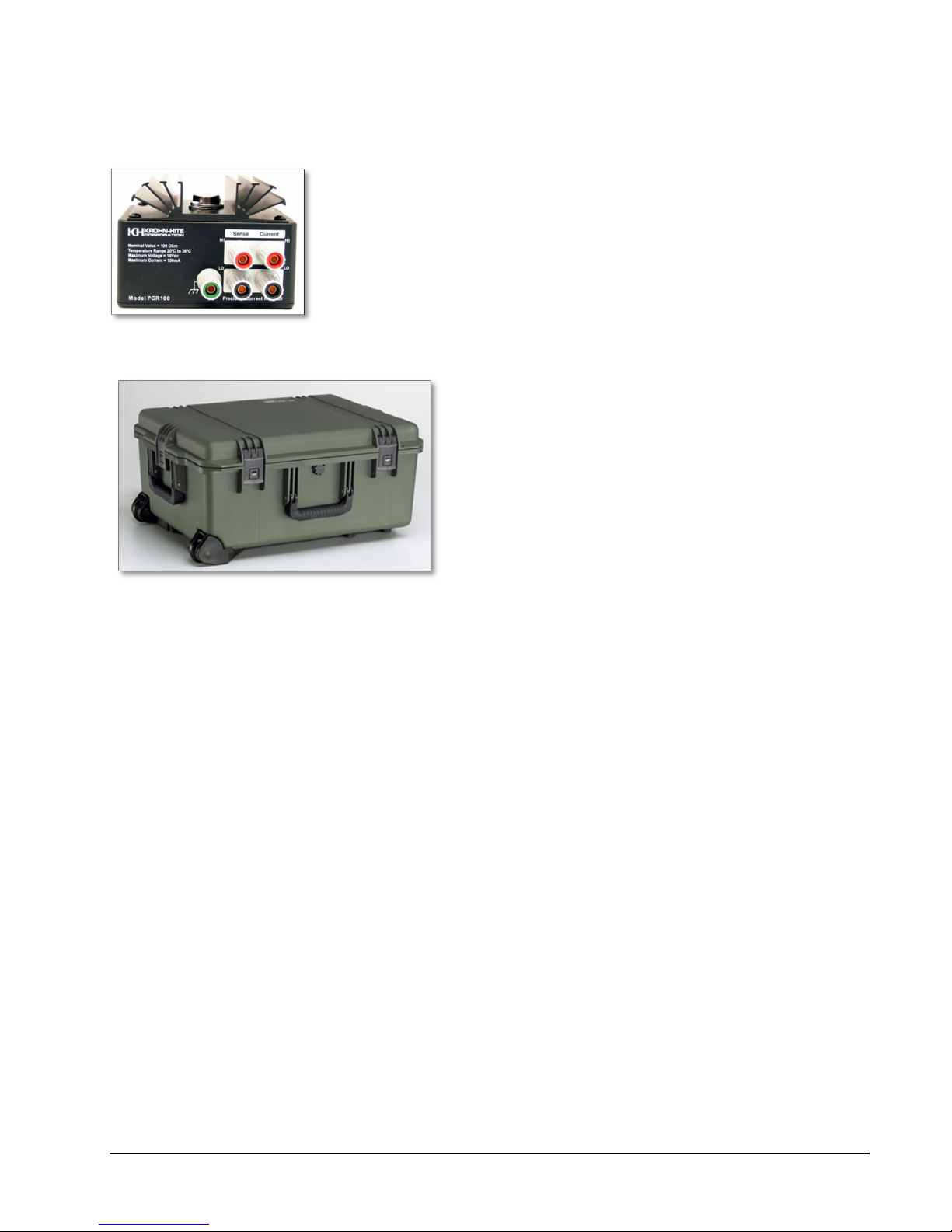
PCR100: 100 ohm Precision Current Resistor used for calibrating the Model 523 in the Current Mode.
Figure 1.6 – 100 Ohm Precision Resistor, PCR100
Case-2720B: Carrying Case
Figure 1.7 – Model 523 Carrying Case
1.12.9 Accessories
3 terminal line cord.
Operating manual.
[7]

Model 523 DC Source/Calibrator
_________________________________________________________________________________
Notes
_______________________________________________________________________________________
_______________________________________________________________________________________
_______________________________________________________________________________________
_______________________________________________________________________________________
_______________________________________________________________________________________
_______________________________________________________________________________________
_______________________________________________________________________________________
_______________________________________________________________________________________
_______________________________________________________________________________________
_______________________________________________________________________________________
_______________________________________________________________________________________
_______________________________________________________________________________________
_______________________________________________________________________________________
_______________________________________________________________________________________
_______________________________________________________________________________________
_______________________________________________________________________________________
_______________________________________________________________________________________
_______________________________________________________________________________________
[8]
 Loading...