

Krohn-Hite 4402B Operating Manual

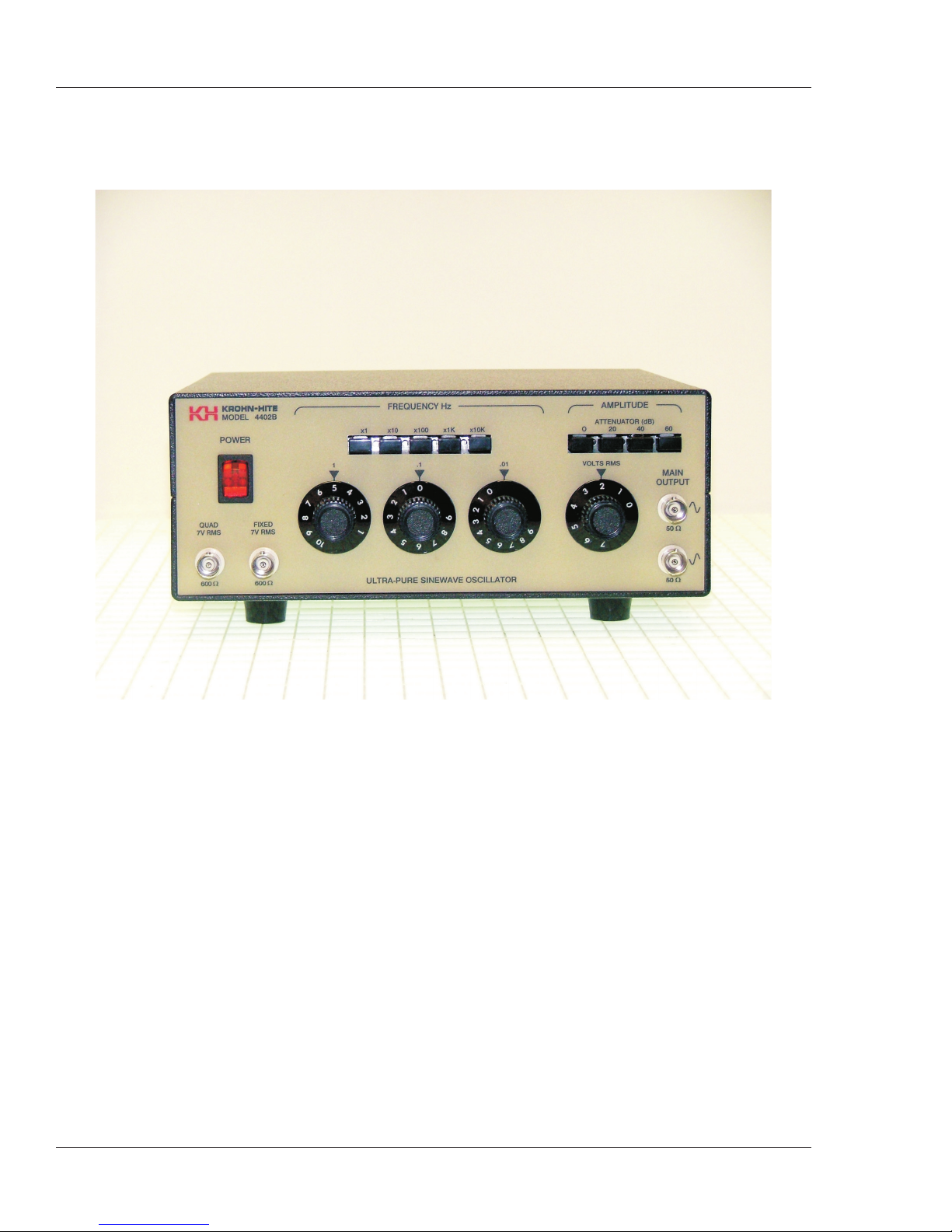
Model 4402B
Ultra-Pure Sinewave Oscillator
1Hz to 110kHz
Typical Distortion of 0.0005%
Serial No. ____________
Operating Manual
15 Jonathan Drive, Unit 4, Brockton, MA 02301 U.S.A.
Tel: (508) 580-1660; Fax: (508) 583-8989
www.krohn-hite.com; info@krohn-hite.com
Copyright © 2006 Krohn-Hite Corporation. All rights reserved. Contents of this publication may not be reproduced
in any form without the written permission of Krohn-Hite Corporation. Printed in USA - 7/06.


Table of Contents
TABLE OF CONTENTS
SECTION 1 . . . GENERAL DESCRIPTION ............1-1
1.1 .....INTRODUCTION .....................1-1
1.2 .....SPECIFICATIONS ....................1-1
1.2.1 . . FREQUENCY .......................1-1
1.2.2 . . MAIN OUTPUTS .....................1-2
1.2.3 . . FIXED OUTPUT .....................1-2
1.2.4 . . QUADRATURE OUTPUT ................1-3
1.2.5 . . GENERAL .........................1-3
1.2.6 . . OPTIONS ..........................1-3
SECTION 2 . . . OPERATION ..................... 2-1
2.1 .....POWERREQUIREMENTS...............2-1
2.2 .....OPERATINGCONTROLS AND CONNECTORS . 2-2
2.2.1 . . REAR PANEL .......................2-2
2.3 .....OPERATION........................2-3
2.3.1 . . FREQUENCY CONTROL ................2-3
2.3.2 . . AMPLITUDE CONTROL ................2-3
2.3.3 . . FLOATING GROUND ..................2-3
SECTION 3 . . . INCOMING ACCEPTANCE ............3-1
3.1 .....INTRODUCTION .....................3-1
3.2 .....LISTOFEQUIPMENTREQUIRED.........3-1
3.3 .....PROCEDURE .......................3-2
3.3.1 . . DC LEVEL ADJUSTMENTS ..............3-2
3.3.2 . . FREQUENCY ACCURACY ..............3-2
3.3.3 . . MAIN OUTPUT AMPLITUDE.............3-2
3.3.4 . . AMPLITUDE FLATNESS ................3-3
3.3.5 . . OUTPUT DISTORTION .................3-3
SECTION 4 . . . CIRCUIT DESCRIPTION .............4-1
4.1 .....THEORYOFOPERATION...............4-1
4.2 .....AVCOPERATION ....................4-2
SECTION 5 . . . MAINTENANCE................... 5-1
5.1 .....INTRODUCTION .....................5-1
5.2 .....EQUIPMENTREQUIRED ...............5-1
5.3 .....PRELIMINARYSET-UP ................5-2
5.4 .....PROCEDURE .......................5-2
Table of Contents - i

Model 4402B Ultra-Pure Sinewave Oscillator
SECTION 6 . . . CALIBRATION ................... 6-1
6.1 .....INTRODUCTION .....................6-1
6.2 .....EQUIPMENTREQUIRED ...............6-1
6.3 .....TEST PROCEDURE ...................6-2
6.3.1 . . POWER SUPPLY CHECK ...............6-2
6.3.2 . . AVC ADJUSTMENT ...................6-2
6.3.3 . . OUTPUT DC LEVEL ADJUSTMENT ........6-2
6.3.4 . . FREQUENCY CALIBRATION (Bands x1-x 1k) . 6-2
6.3.5 . . FREQUENCY CALIBRATION (x10k Band) ....6-3
6.3.6 . . DISTORTION CHECK..................6-3
SECTION 7 . . . PARTS LIST ..................... 7-1
7.1 .....INTRODUCTION .....................7-1
ii - Table of Contents

Section 1
Figure 1.1 . Typical Output Distortion ...............1-3
Section 2
Figure2.1.OperatingControlsandConnectors .........2-1
Section 3
Figure 3.1 . Test Set-Up for Measuring Amplitude Flatness. . 3-2
Figure3.2.AmplitudeFlatnessTestSet-Up ...........3-3
Table of Contents
FIGURES
Section 4
Figure 4.1 . Model 4402B Simplified Block Diagram ......4-1
Figure4.2.SimplifiedAVCDiagram................4-2
Section 5
Figure 5.1A. . Troubleshooting Flowchart.............5-3
Figure 5.1B. . Troubleshooting Flowchart.............5-4
Table of Contents - iii
Model 4402B Ultra-Pure Sinewave Oscillator
iv - Table of Contents
Model 4402B Sinewave Oscillator

General Description - Section 1
SECTION 1
GENERAL DESCRIPTION
1.1 INTRODUCTION
The Model 4402B is an ultra-pure sinewave, stable amplitude oscillator designed to meet the needs of to
day’s high precision 16 to 18 bit A/D converter testing, and audio test and measurement technology.
-
Covering the frequency range from 1Hz to 110kHz, with precise 3 digit frequency tuning, the 4402B pro
duces a virtually “distortion-free” (<0.0005%) sinewave for measuring A/D converter accuracy, audio
preamplifier and power amplifier harmonic distortion. With its exceptionally flat response (0.02dB), the
4402B eliminates the need to constantly monitor voltage levels, during frequency response tests.
The 4402B provides a 7Vrms sinewave output, (balanced output, 14Vrms end-to-end), 3.5Vrms into 50
ohms, and has no loss in performance when loaded with a linear 50 ohm load.
A 3-position, push-button attenuator calibrated in 20dB steps, along with the a 30dB vernier, provides a
total dynamic range of 90dB.
Simultaneous fixed and quadrature (90°) outputs are provided. Each output is 7Vrms with 600 ohm
source impedance.
The 4402B is the perfect addition to your present test and/or precision measurement set-up.
1.2 SPECIFICATIONS
The following specifications apply to the Main, Quadrature and Fixed Outputs, except where noted.
1.2.1 FREQUENCY
Range: 1Hz to 110kHz.
Accuracy: ±0.5% of frequency setting.
-
Control: 2 digits of frequency, calibrated in 1Hz and 0.1Hz steps, with a calibrated vernier providing
continuous coverage between the 0.1Hz steps, plus a 5 decade push-button multiplier with overlapping
ranges.
Stability:
Vs. Time: 0.01% in 1 hour or less.
Vs. Temperature: 0.05%/°C.
Vs. Line: <0.001% for a 10% change in line voltage.
General Description - 1-1

Model 4402B Ultra-Pure Sinewave Oscillator
1.2.2 MAIN OUTPUTS
Maximum Amplitude: 7Vrms open circuit (balanced output, 14V rmsend-to-end); 3.5Vrms; +48dBm
into 50 ohm load (balanced output, 7V rms end-to-end).
Impedance: Constant 50 ohms.
Maximum Current: 75mA rms.
Minimum Amplitude: <0.2mV.
Amplitude Flatness: ±0.02dB, 1Hz to 110kHz.
Amplitude Stability:
Vs. Time: 0.01% in 1 hour or less.
Vs. Temperature: 0.05%/°C.
Vs. Line: <0.001% for a 10% change in line voltage.
Amplitude Control: A 4-position push-button attenuator calibrated in 20dB steps from 0dB to –60dB,
Accuracy, ±0.25dB/20dBstep; Volts rms control with greater than30dB of coveragecalibrated involts.
Accuracy: ±20% of setting.
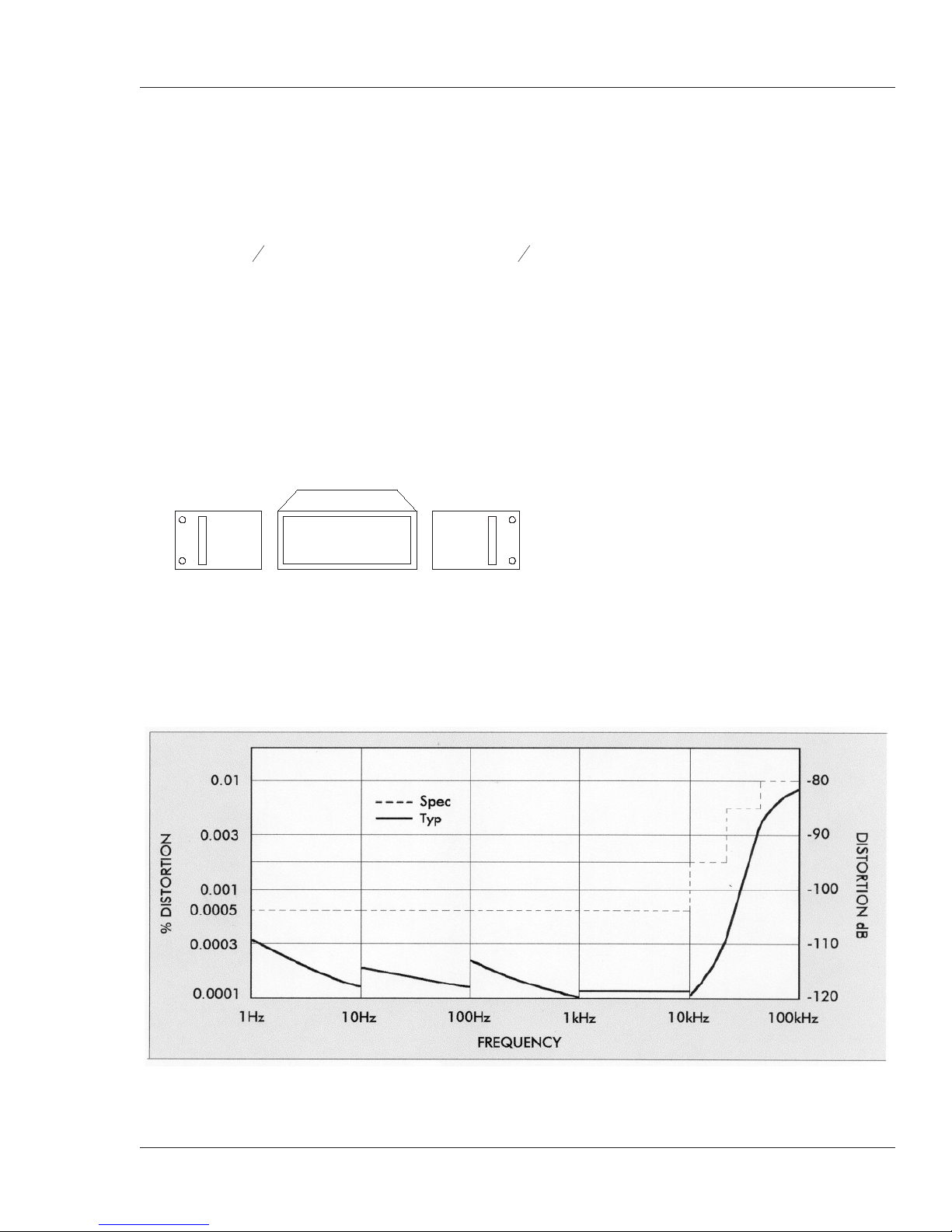
Main Output Distortion:
Frequency Distortion % Distortion (dB)
1Hz to 10kHz <0.0005 –106
10kHz to 20kHz <0.0018 –95
20kHz to 50kHz <0.0056 –85
50kHz to 110kHz <0.01 –80
Hum and Noise: Greater than 110dB below signal (10Hz to 20kHz detector bandwidth).
1.2.3 FIXED OUTPUT
Amplitude: 7V rms open circuit; 3.5V rms (+13dBm) into 600 ohm load.
Impedance: Constant 600 ohms.
Amplitude Flatness, Amplitude Stability and Distortion: Same as Main Output.
Phase Accuracy (180°, top BNC, Main Output): 1Hz to 10kHz, ±0.4°; 10kHz to 110kHz, ±5°.
1.2.4 QUADRATURE OUTPUT
Amplitude: 7V rms open circuit; 3.5V rms (+13dBm) into 600 ohm load.
Impedance: Constant 600 ohms.
Amplitude Flatness: ±2dB, 1Hz to 110kHz.
Amplitude Stability: Same as Main Output.
Phase Accuracy (–90°): 1Hz to 1kHz, ±0.2°; 1kHz to 10kHz, ±1°; 10kHz to 110kHz, ±10°.
1-2 - General Description
General Description - Section 1
1.2.5 GENERAL
Ambient Temperature Range: 0°C to 50°C.
Power Requirements: Switch selectable, 90-132 or 180-264 volts, single phase, 50-60Hz, 18 watts.
Floating Ground: Rear panel switch floats circuitry ground from chassis ground up to 100V.
Dimensions: 3
1
“ (8.9cm) high, 9" (23cm) wide, 8
2
1
” (21.6cm) deep.
2
Weights: 5 lbs (2.3kg) net; 7 lbs (3.2kg) shipping.
Accessories: 3-terminal line cord and operating manual.
1.2.6 OPTIONS
Rack Mounting Kit: Part No. RK-39 permits the installation of the Model 4402B into a standard
19"rack spacing.
Optional Rack Mount Kit RK-39
Extended 1 Year Warranty: Part No. EW4402B.
Figure 1.1 Typical Output Distortion
General Description - 1-3


Operation - Section - 2
SECTION 2
OPERATION
2.1 POWER REQUIREMENTS
The Model 4402B is powered froma single phase, 50Hzto 60Hzac linevoltage ofeither 90Vto 132V or
180V to 264V. A selector switch on the rear panel selects the desired voltage range.
The fuse receptacle on the rear panel contains 1/4A slow-blow fuse for 120V operation and a 1/8A fuse
for 240V operation.
Figure 2.1 Operating Controls and Connectors
Operation - 2-1

Model 4402B Ultra-Pure Sinewave Oscillator
CAUTION!
The cover of this instrument should not be removed when
the instrument is connected to an ac line power source,
because of the potentially dangerous voltages that exist
within the unit.
2.2 OPERATING CONTROLS AND CONNECTORS
(see Figure 2.1 at the end of this section)
1. Power: On-off rocker switch with power-on indicator.
2. Frequency Hz: 2 rotarydecade switchescalibrated in1Hz steps(1-10) and0.1Hz steps (0-9), plus a
calibrated vernier providing continuous coverage between the 0.1Hz steps. A 5-band push-button
multiplier multiplies the frequency setting in decade steps from x1tox10k.
3. Amplitude: 4-position push-button attenuator calibrated in 20dB steps from 0dB to 60dB, plus a
single-turn VOLTS RMS control with greater than 30dB of coverage. Dynamic output range 0dB
to –90dB.
4. Main Output: 2 BNC connectors. Maximum output, 7Vrms open circuit (14Vrms end-to-end, bal-
anced) and 75mA rms loaded with a linear 50 ohm load. Output Impedance, 50 ohms, ±1%.
5. Fixed 7Vrms: BNC connector. Fixed at 7Vrms open circuit. Output is inverted by 180° on the top
Main Output BNC; and is in phase with the bottom Main Output BNC (see Figure 2-1). Output impedance 600 ohms, ±1%.
6. Quad 7Vrms: BNC connector. Fixed at 7Vrms open circuit. Quadrature (90°) with respect to top
Main Output BNC. Output impedance, 600 ohms, ±1%.
2.2.1 REAR PANEL
7. Main Output DC Level (bottom BNC): Screwdriver control for periodic adjustment of the Main
Output DC Level.
8. Main Output DC Level (top BNC): Screwdriver control for periodic adjustment of the Main Out
put DC Level.
9. Circuit Ground: Slide switch. In the FLOATING mode, the signal ground becomes disconnected
from chassis ground.
10. AC Power Receptacle: Standard, 3-prong connector complies with European I.E.C. standard. A
detachable, 3-wire line cord is included.
-
11. Line: Slide switch. Use 120Vposition for acline voltagesbetween 90Vto 132V; use 240Vposition
for ac line voltages between 180V to 264 V.
12. Fuse Receptacle: Use a 1/4A, slow-blow fuse for 120V operation and 1/8A, slow-blow fuse for
240V operation.
2-2 - Operation

Operation - Section - 2
2.3 OPERATION
2.3.1 FREQUENCY CONTROL
The frequency of the 4402B is controlled by 2 rotary decade switches, a 3rd digit vernier and a 5-decade
multiplier. The decade switches are calibrated in 1Hz steps from 1 to 10 and 0.1Hz steps from 0 to 9. The
3rd digit vernier is calibrated from 0->9, and provides additional resolution between the 0.1Hz steps.
The 5-band push-button multiplier is calibrated in decade steps from x1tox10k.
Multiplier Frequency Range
x1 1.00Hz to 11Hz
x10 10.0Hz to 110Hz
x100 100Hz to 1.1kHz
x1k 1.00kHz to 11kHz
x10k 10.0kHz to 110kHz
2.3.2 AMPLITUDE CONTROL
The Main Output control is controlled by a 4-position push-button attenuator; and a single turn variable control. The attenuator is calibrated in 20dB steps from 0dB to 60dB. The VOLTS RMS control
is calibrated in volts and provides an additional 30dB coverage on each attenuator position.
Attenuator
Volts RMS Range
(Main Output)
0dB 220mV to 7V
20dB 22mV to 700mV
40dB 2mV to 70mV
60dB 220µV to 7mV
To optimize the resolution of the adjustment, use the lower of the two attenuator settings (e.g. if the ap
plication requires a 500mV rms signal, use the 20dB setting rather than the 0dB setting).
The Quad (90°) and Fixed (180° out of phase from top Main Output BNC) outputs are fixed at
7Vrms. The output impedance of each of these outputs is 600 ohms.
2.3.3 FLOATING GROUND
The CIRCUIT GROUND switch on the rear panel allows the oscillator to “float” or isolate the oscillator
circuit or signal ground from the chassis or earth ground. Maximum allowable DC isolation is 100V.
-
Operation - 2-3

Model 4402B Ultra-Pure Sinewave Oscillator
This page intentionally left blank.
2-4 - Operation
 Loading...