

Krohn Hite 4200 User Manual

I
,-_-'l
xkoHN-HlrE
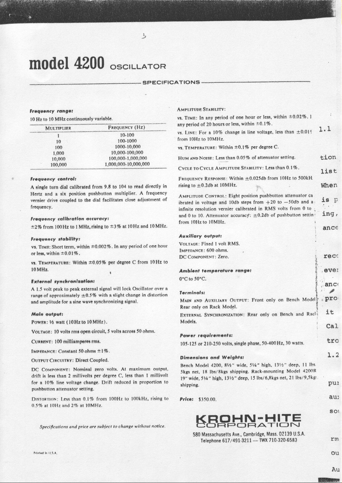
1O Hz
1O MHz
to
c<:RPoRATlc>N
)-.
()SCILLATOR
TEST
Model
t
Frequcncy
r
Powor
o
l{axlmvm
t
Frtqvency
s
Hormonlc
t
t
t
c
e
The
tory
onty
over
less than
at
push-button
quency
The
for
excellent
4200 ideal
and
Amplitude
position
8
A
provides
ovlpvl, Vz
Amplitvdc
Frcquancy
lnlsrnsl
Avxlllory
Exlcrnal
4200
Model
production signal
or
units selling
in
range from
the
tuning.
watt of
half
general purpose test
a
frequency
amplifier testing.
calibration
push-button
continuous
90db of
C)5CILLAT()R
42OO
tangct
output:
rcfponrf,
dlstortlont O.lVo
stabllltyr
accarccy2 2Vo
lmpcdoacc:
outpul
synchronixallon
0. I 7o
multiplier
for meter
output
lOHzto
watt
volts
l0
0.025 db
4.027o
50 ohms
a low
Oscillator
is
source
| 0 Hz
the
to l0 MHZ
An infinite
at twice
distortion"
provides rapid
power
over
the enlire
oscillator,
response
of
calibration,
of 0.2db
atienuator calibrated
control
combined
attenuation.
price' It
lOMI{z
rms
priced
solid
state
with performance
,t
w^tl
a sine wave
provides
with
resolution
continuous
and
outstanding
is
range
and this
0.025db,
response
accuracy
coupled
the Model
makes
measurements
is obtained
in l0db
with
the attenuator
labora-
available
power
of
and
dial
fre-
with an
an
by
steps.
F-'t
f..T[l
rrcl
l-Tl
xultrtrtli ?
ohm
50
T'he
and capacitive
sistive
essential
Unavoidable
oscillator
output
A
rused
increased
available
quency
Careful
and use of
vibration
quency
ideally
for driving
without
capabilities.
volt output
I
fixed
for synchronizing
frequency
to
source,
attention
all silicon
and shock.
range,
suited
1t'o
-.-
g'
---*
impedance
loading
loads
capacitive
internal
low
independent
a
accuracy,
the Model
lock
packaging design, rtrgged
to
transistors
The
response,
flat
laboratory
for
nnd
gjgnal
the half
minimizes
without overloading.
loading limits
the usefulness
impedance
the main output
of
auxiliary
as an
or
scope
a
synchronizing
precise
4200 to
Model
clean
end
a
this unit
makes
with its broad fre-
4200
signal
production
of
to
power
losses due
watt
of
power
high
and
can
otltput.
input
external fre-
conslruction
insensitive to
price'
low
and
applications.
re'
is
any
be
For
is
is
,
E2
z
ol
F
F.i
F
o
6.2
t.'
t.l
o
E
rl
t
t
.ot
"et
.ol
,tt
6
I
.oe
I
gpEctFrctTroil
\\
I
tor tO.
tYPrcl|-
r|lrrT3
FifOUENCY
ol3TonTloll
lHrl
toi
to.
U
9o
ts
d
I
t.l
.or
lpEcrFtcriron
tor
TVFTCAL
riEOufrCV
TiEOUEf,CY
trurtt
I
rd tor
{Hrl
iESPOIISE
lor
rd
3
mOdgl
|rr,qucncy
l0 He
lrsqocncy
cinglc turn dirl
A
llerte and a
vcrnicr
frCquency.
Frsqucncy
*29o
Froqvancy *|abllllyt
vs.
TlMe:
orlctg.within
Tsutamtune;
w.
lOMHz.
xl * n al
3
A 1.5
range of
amplitude for a sinc
and
lllala
Powm:
Vottrce:
Cunrnxt:
IMPEb^NcE : Conitrnt
Ourprn
DC CoMpoNEtrt:
drift ir
for e lt?o
purhbutton
DrstonnoN: [,ess
OSVo
ranget
to l0 MHe
MUL-npLIER
drive
lrom l00Ht
volt
oulputt
ters than 2
al f
continuously
I
l0
100
1,000
10,000
1oCI,000
Goritrot,
calibrutcd
position pushbutton
sir
couplcd
colf brollqr
!o I MH4
term.
Short
*0.OlTo.
sy n
chcanlrollont
pcak
pcak
to
approximatcly
(l0Htto
9t watt
voltr
l0
mlllhmfi*r$
100
Crnctnfiv:
voliage
linc
ettenuator
OHe and 27o at lQMHt.
4U00
varlsblc.
from 9.6
faeilitates closc
dial
to thc
cccvtacy,
riring to
=0.002To.|n
within
+0,05fo
Wiibin
external
'+O.S%
wt e
rmr
opcn
56 66s1;
Dirdt
Nominel zero
millivolts
reltinS.
than
signal
with
rynchronizing
l0MHz).
clrcuit,
rmr.
*.
lVo.
Coupled.
per
degree
changc.
0.17o from l00Hz
Drift
os'LLAroR
SG'ECIFICATIONS
FRreuENcY
1000-10,000
10,000-100,000
100.000-1,000,000
1,000,000-
to 104
multipllcr.
=!%
per
dogrcc C
I
will
a rlight
volr
!
volts. At maximum
reduced
(llz)
t0-100
100-1000
10,000,000
to rcad directly
A frequcncy
adjustment
at l0Hz
any
lock Oscillator
ecrom J0 ohmr.
C.
nnd l0MHz.
pcriod
of onc
from
in distorlion
change
rignal,
less than I
proportlon
in
to l00kHz,
in
of
hour
to
l0Hz
over
output'
millivnlt
rising
AMPLTUDE
vl. TtuE: ln
period
any
vr.
Lttr:
from t0Hz
w. TEMpEnrTUnT:
^ND Notsr:
HuM
To CycLE
CycLE
Fneeurr'lcv
to
rising
AMpLrruDE
ibrated
inffnite
to
and 0
from l0Hz
Auxlllary
Vortlca: Fixed
lursorxce:
CouroNext:
DC
Amblcnl
to
0'C
50'C.
a
lcrrnfnalsl
rno Auxtll^nY
Mtlx
only on
f,car
Extenxrt
Modcls.
Powcr
l0J-l2J or 210-2J0
Dlnicndnnr
Bench
5kgr net,
wide, J14'high, ltVz" decp,
19"
to
shipping.
to
Prlcc:
StrntI.rrY:
period
any
hours
of 20
For a l07o
to lOMHz.
Within
Less
AMpr.truDE
Rr.spoxss:
f0.2db
in
resoluiion
Model
at l0MHz.
Coxrnol:
voltagc and
vernier calibratcd
Attenuator
10.
to l0MHz.
ovlpat,
volt RMS.
I
ohms.
600
Zero.
ttmpctolura
Mod-el.
Rack
Svxcgnoutzenox:
tcquiromlnltt
voltr,
Wcfghtr:
ond
42AO,
lE
lbslSkgs
$350.00.
of one hour
within
less,
or
change in
a0.l% per
0.0J% of
than
St,rntLtl'Y
Within
position
Eight
steps from
l0db
accuracy:
rongat
Ourput:
tingle
wide, SVt"
E t"
ehipping.
within
less,
or
lA'lfo,
voltage,
line
C.
degrec
attenuator
:
Lcss
{'0.025db
from
;:
pushbutton
+20
in RMS
+0.2db
of
Front only on
Rear onty
phasc,
Rack-mounting
l5lbr/6,8kgs
on
50-400H2,
high, l3%"
*0.02%'
retting.
7a
+0.019
.
less than
than 0.1
lOHz to 500kH:
,
attenuator ca
-50db
Bench
and
wltts.
30
deep' I
Model
lbslg,Jkgl
and a
0 to
settin'
Model
4200R
to
volts from
pushbutton
Bench
nct, 2l
Racl
lbs'
I
I
1.r
tiOn
Iist
l{hen
! -
v
*-
,
ing
t
t
anc6
i
I
rgcc
,eveI
allC(
,.,
''
,
,
PrO'
1r
t
CaI
O
tf
I.2
PUt
au:
801
Specifcations
Prlnlod
1,.3,A
In
and
prlcc
arc
subiect
to
changc
e,irhout
notice.
SBSHIHtS,gS
Massachusetts
580
Ave., Cambridge,
Telephone 617/491-3211
Mass.
-
710'320-5583
TWx
U'S.4.
02139
trm
ou
Au
ml
r{
0.02%.
-r-o.01
I
'/o,
0 J00k
Uator
lb
and
rm0!o
0n
i
1.1
tionE
ligt
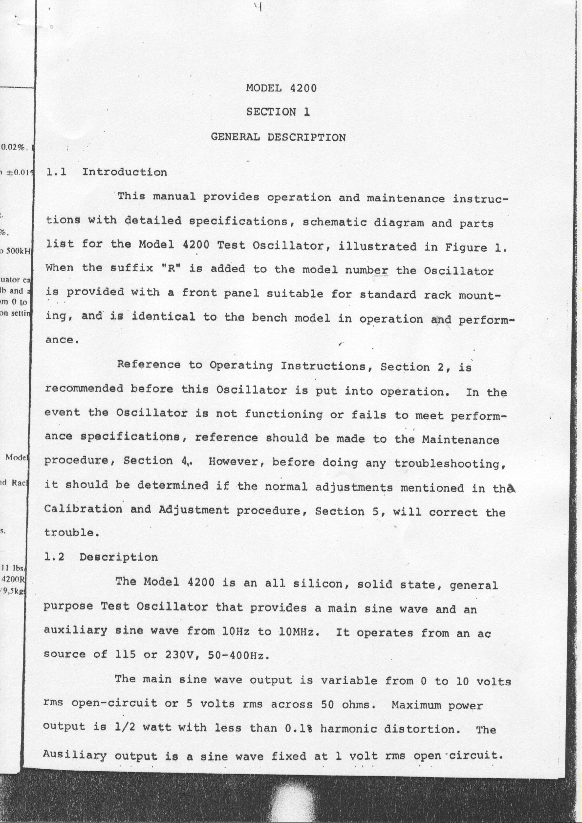
when the
*f.nrovided
ing' and
ance
Introduction
with
for
I
'This
the
suffix
l.e
manual
detailed
Model
*3rr
with
identical
a
Reference
MODEL
sscTroN I
GENERAL
provides
epecificatipns
{200
front
Test
iE added
panel
to
the bench
operating
to
oecillator,
to
42OO
DESCRTPTION
operation
sqhematic
r
the model
suitable
model
and
lllustrated
number
for
in
t
rnstructione,
maintenance
diagram
the
standard
operation apd
sectiotr
and
ln
Flgure
ossillator
rack
2, is
instruc-
parts
I.
mountperform-
,'
rt
tt
42A0
/9,str
recommended
event
ance
the
epoclflcationsr
procedurep
it
should be
before
Oscillator
Section
deterrnined
callbrat,lon'and
trouble.
L,2
Deecrlption
The
purpose
auxiJ.iary
souree
Test
qf
ogcillator
sLne
ll5 or
this
ie not
reference
4,.
AdJuatment
Model
wave
4zaa
from
230V,
Oscillator
functioning
should
Hatutever,
tf the
normaL
procedure,
is
an
al"l.
r0Hz
provides
to
that
50-400H2.
ls
before
ellicon,
l0MHz.
put
or
be
made
doing
into
operation.
faiLs
to the
any troubleshooting,
adjrretments
section
s, wirl
sorid
a main
sLne
rt
operates
fn
the
to meet perform-
Maintenance
mentioned
correct
etate,
wave
and
fro:n
in
thA
the
genera1
an
an
ac
rms
open-circuit
output
ie
AusiJ.iary
The
main
L/2
watt
output
sLne
or
wtth
tg
wav€
5 volts
leeE
a sine
output
rms
across
than 0.Lt
xrave
fixed
is
variabLe
50 ohms.
harnonic
at I voLt
from
0 to
10 vol.ts
Maximum povrer
distortion.
rms
open'circuit.
The
)
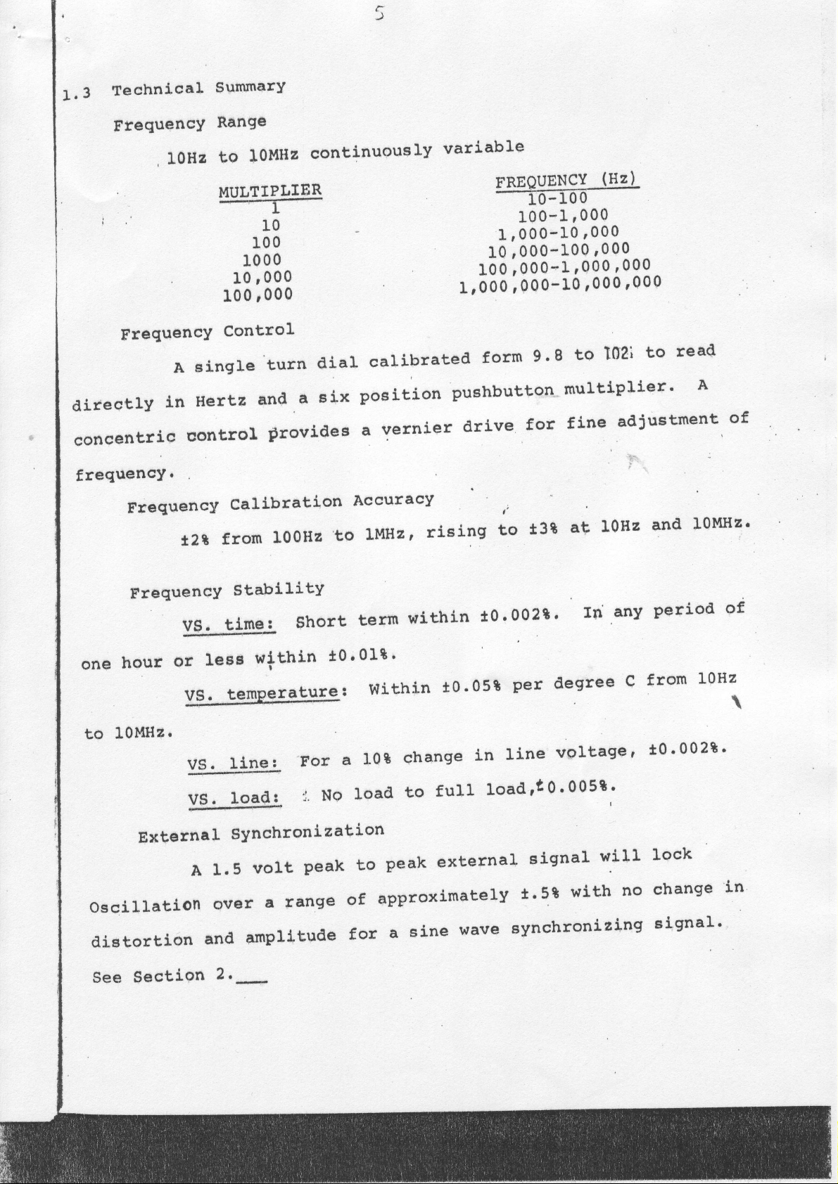
1.3
fechnical
FrequencY
I0Hz
i"10
.
FrequencY
directlyinHertzand'asixpositionpushbuttonmult,ip}ier.A
concentric
frequencY.
SummarY
Range
I0!4Hz
to
MULTIPLIER
--I-
I00
000
1
10
1000
000
100
'
Control"
Asingleturndialcallbratedformg.Stol02it,oread
control
continuously
provides
vernier
a
variable
TREQUENCY
-T6mr-
100-1 ,000
1,000-I0
L0,000-100
100;000-r
trooo rooo-ro
drive
for
'000
'000
r00o
fine
(HZ)
r00o
-
'000
'000
adjust'ment,
of
FrequencY
FrequencY
hour
one
lOMHzr
to
External
oscilLat,ion
distortion
*.2*
V$,.
or
VS.
VS.
Vs.
A
Callbration
from
ti,me:
less
,lemfleratqre:
lilq:
1'5
ov€r
and
100H2
StabiLitY
$hort
within
For
No
lo3q
SYnchronization
volt
amplit'ude
i.
range
a
:r'
peak
AccuracY
LMHz
to
term
tO'OIt'
Wit'hin
10*
a
loacl
to
approximately
of
fot
rising
'
within
change
to
peak
sine
a
t
to
t0'002t'
t0'05*
in
full
external
Load
wave
L0Hz
at
t3B
In
degree
per
line
synchronizing
voltagel
005t
'
0
't
signa)'
t.5t
with
'
I
w'iIl
any
C
no
I0MHz'
and
period
from
I0Hz
t0.002t.
lock
change
signal.
of
\
in
See
$ection
2.-
 Loading...