

Krohn-Hite 3940, 3944 Operating And Maintenance Manual
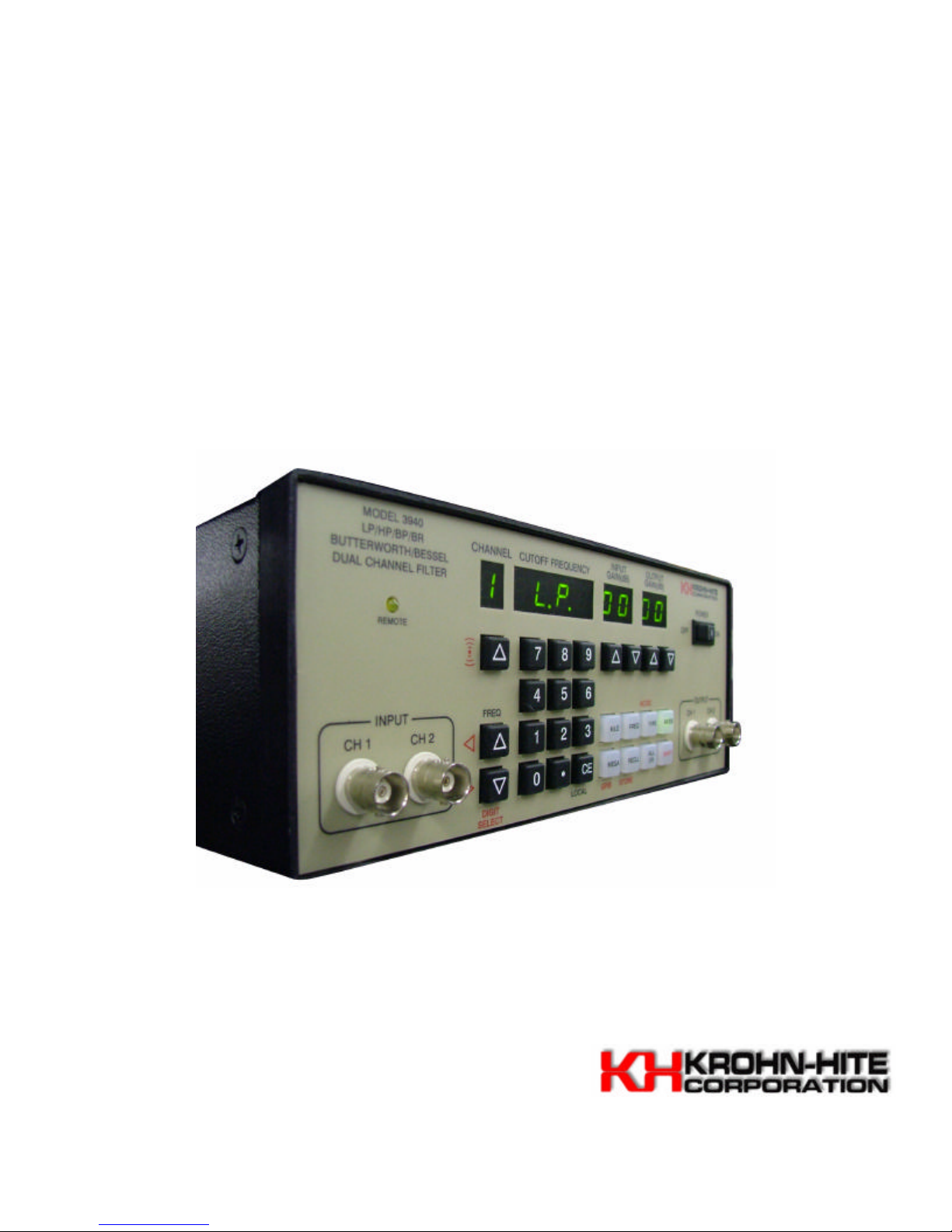
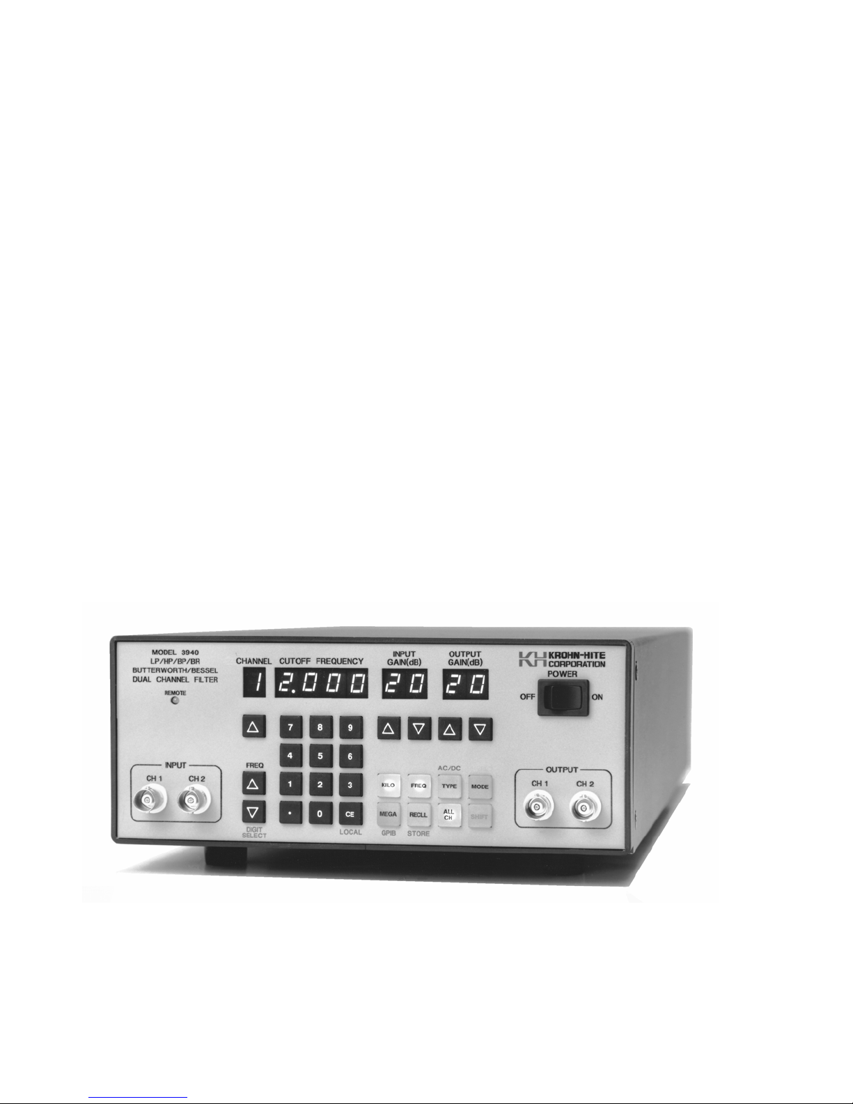
Model 3940/3944
Programmable (IEEE-488) Filter
3Hz to 2MHz
LP, HP, BP, BR
Operating and Maintenance Manual

Service and Warranty
Krohn-Hite Instruments are designed and manufactured in accordance with sound engineering
practices and should give long trouble-free service under normal operating conditions. If your
instrument fails to provide satisfactory service and you are unable to locate the source of trouble,
contact our Service Department at (508) 580-1660, giving all the information available concerning the
failure.
DO NOT return the instrument without our written or verbal authorization to do so. After contacting us,
we will issue a Return Authorization Number which should be referenced on the packing slip and
purchase order. In most cases, we will be able to supply you with the information necessary to repair the
instrument, avoiding any transportation problems and costs. When it becomes necessary to return the
instrument to the factory, kindly pack it carefully and ship it to us prepaid.
All Krohn-Hite products are warranted against defective materials and workmanship. This warranty
applies for a period of one year from the date of delivery to the Original Purchaser. Any instrument that
is found within the one year warranty period not to meet these standards, will be repaired or replaced.
This warranty does not apply to electron tubes, fuses or batteries. No other warranty is expressed or
implied.
Krohn-Hite Corporation reserves the right to make design changes at any time without incurring any
obligation to incorporate these changes in instruments previously purchased.
Modifications to this instrument must not be made without the written consent of an authorized
employee of Krohn-Hite Corporation.

3Hz TO 2MHz
Butterworth/Bessel
Low-Pass/High-Pass/Band-Pass/Band-Reject
Programmable Filter
MODELS
3940 and 3944
SERIAL NO.________
OPERATING AND
MAINTENANCE MANUAL
15 Jonathan Drive, Unit 4. Brockton, MA 02301-5566
E-mail: info@krohn-hite.com; Web: www.krohn-hite.com
Tel: (508) 580-1660; Fax: (508) 583-8989

TABLE OF CONTENTS
SECTION PAGE
1.0 GENERAL DESCRIPTION
1.1 INTRODUCTION..............................................................................................................1
1.2 SPECIFICATIONS............................................................................................................1
1.2.1 Filter Characteristics............................................................................................1
1.2.2 Input.....................................................................................................................2
1.2.3 Output..................................................................................................................2
1.2.4 General................................................................................................................2
1.2.5 Options ................................................................................................................3
2.0 OPERATION
2.1 INTRODUCTION..............................................................................................................5
2.2 TURN-ON PROCEDURE.................................................................................................5
2.3 SELF TEST.......................................................................................................................5
2.4 FRONT PANEL CONTROLS AND DISPLAY..................................................................5
2.4.1 Data Keys and Display........................................................................................5
2.4.2 Parameter and Control Keys...............................................................................5
2.4.3 Channel Selection ...............................................................................................7
2.4.4 Cutoff Frequency.................................................................................................7
2.4.5 Input Gain (Pre-Filter)..........................................................................................7
2.4.6 Output Gain (Post Filter)......................................................................................7
2.4.7 Digit Select/Increment and Decrement................................................................7
2.4.8 Key Click Feature On/Off.....................................................................................8
2.5 REAR PANEL CONTROLS AND CONNECTORS..........................................................8
2.5.1 Introduction..........................................................................................................8
2.5.2 BNC Connectors..................................................................................................8
2.5.3 DC Level Adj........................................................................................................8
2.5.4 Power...................................................................................................................8
2.5.5 GPIB Connector ..................................................................................................8
2.6 FILTER OPERATION.......................................................................................................8
2.6.1 Introduction..........................................................................................................8
2.6.2 Variable Band-Pass and Band-Reject Operation................................................8
2.6.2.1 Band-Pass...........................................................................................8
2.6.2.2 Band-Reject.........................................................................................8
2.6.3 Amplitude Response ...........................................................................................9
2.6.4 Phase Response.................................................................................................9
2.6.5 Group Delay ........................................................................................................10
2.6.6 Transient Response ............................................................................................11
3.0 IEEE-488 STD (GPIB) PROGRAMMING
3.1 INTRODUCTION..............................................................................................................13
3.2 PRELIMINARY PROGRAMMING INFORMATION..........................................................13
3.2.1 GPIB Primary Buss Address...............................................................................13
3.2.2 IEEE-488 Bus Interface Programming Connector ..............................................14

3.3 ASCII DATA COMMANDS...............................................................................................14
3.3.1 Format .................................................................................................................14
3.3.2 Types of Data Commands...................................................................................14
3.3.3 Table of ASCII Commands..................................................................................15
3.3.4 Examples.............................................................................................................16
3.3.4.1 Example 1 ...........................................................................................16
3.3.4.2 Example 2 ...........................................................................................17
3.3.4.3 Example 3 ...........................................................................................17
3.4 IEEE-488 STANDARD COMMANDS...............................................................................18
3.4.1 Multi-Line Message .............................................................................................18
3.4.2 Polling Commands ..............................................................................................19
3.4.2.1 Parallel Polling.....................................................................................19
3.4.2.2 Service Requests and Serial Polling...................................................20
3.4.2.3 Serial Responses................................................................................20
3.4.3 Uniline Messages................................................................................................21
3.5 TALKER FORMAT ...........................................................................................................22
3.5.1 Parameter Information Format............................................................................22
3.5.2 Model Number and Software Version Format.....................................................22
3.6 PROGRAMMING EXAMPLES.........................................................................................22
3.6.1 Example 1 – Microsoft Quick Basic.....................................................................22
3.6.2 Example 2 – Borland Turbo C.............................................................................23
3.6.3 Example 3 – National Instrument IBIC................................................................28
4.0 INCOMING ACCEPTANCE
4.1 INTRODUCTION ............................................................................................................29
4.2 TEST EQUIPMENT REQUIRED......................................................................................29
4.3 FILTER CHARACTERISTICS..........................................................................................29
4.3.1 Low Pass/High Pass Response..........................................................................29
4.3.2 Cutoff Frequency Accuracy.................................................................................30
4.3.3 Band-Pass/Band-Reject Response.....................................................................30
4.3.4 Stopband Attenuation..........................................................................................31
4.3.5 Pre-filter and Post-filter Gain Accuracy...............................................................31
4.3.6 Noise Check........................................................................................................31
4.3.7 Distortion and Maximum Signal Checks..............................................................32
4.3.8 AC/DC Coupling Check.......................................................................................32
FIGURES
2.0 OPERATION
2.1A Low-Pass Amplitude Response .......................................................................................9
2.1B High-Pass Amplitude Response.......................................................................................9
2.2 Phase Response ............................................................................................................10
2.3 Group Delay ............................................................................................................10
2.4 Transient Response.........................................................................................................11
3.0 IEEE-488 STD (GPIB) PROGRAMMING
3.1 Rear Panel GPIB Connector............................................................................................
4.0 INCOMING ACCEPTANCE
4.1 Band-Pass Response/Band Reject Response.................................................................30
4.2 6kHz High-Pass Filter.......................................................................................................31
4.3 2MHz Low-Pass Filter ......................................................................................................31
TABLES
3.0 IEEE-488 STD (GPIB) PROGRAMMING
3.1 Setting and Displaying GPIB Primary Address................................................................13
3.2 Line-Termination-Character Sequence............................................................................13
MODEL 3940 MULTICHANNEL FILTER

Model 3940 / 3944 Section 1 – General Description
SECTION 1
GENERAL DESCRIPTION
1.1 INTRODUCTION
The Model 3940 (two channels) and the Model 3944 (4 channels) are Butterworth/Bessel Filters with
identical channels covering a tunable frequency range from 3Hz to 2MHz. Each channel can function
independently with either low-pass or high-pass functions at 24dB/octave attenuation, or channels can be
connected in series externally in the same mode to provide 48dB/octave (Model 3940) to 96dB/octave
(Model 3944) attenuation. One channel of band-pass or band-reject operation (Model 3940) or two
channels (Model 3944) are also available.
Either maximally flat (Butterworth) response or linear phase (Bessel) response for pulse signal filtering is
selectable. Both input and output amplifiers provide either 0dB or 20dB of gain per channel.
The filter is controlled by the front panel keyboard or over the IEEE-488 bus. Provided are LED displays
and indicators for input and output gain, cutoff frequency, channel selection and remote operation. Nonvolatile, battery-backed, CMOS memory permits storing and recalling of 99 selectable groups of front
panel settings. Storing and recalling group settings is accomplished with a single command. Self-testing
of the digital circuitry occurs upon power-up.
1.2 SPECIFICATIONS
1.2.1 FILTER CHARACTERISTICS
Functions:
Model 3940: Two independent channels of low-pass, high-pass or by-pass; one channel
of band-pass or band-reject.
Model 3944: Four independent channels of low-pass, high-pass or by-pass; two
channels of band-pass or band-reject.
Type: 4-pole Butterworth (maximally flat) or Bessel (linear phase) per channel.
Frequency Range (fc): 3Hz to 2MHz.
Frequency Resolution: 1Hz from 3Hz to 1kHz; 10Hz up to 2kHz; 100Hz up to 100kHz; 1kHz up
to 1MHz; 10kHz up to 2MHz.
Frequency Accuracy (fc): ±2% or least significant digit (which ever is greater) 20Hz to 500kHz;
±5% to 2MHz.
Relative Gain at fc: Butterworth, -3dB; Bessel, -7.5dB.
Bandwidth: dc to fc, dc coupled; 0.2Hz to fc, ac coupled (low-pass); fc to 10MHz (high-pass).
Attenuation: 24dB/octave per channel.
Stopband Attenuation: >80dB.
Insertion Loss (0dB Input/Output gain): ±0.5dB to 2MHz.
- 1 -

Section 1 – General Description Model 3940 / 3944
1.2.2 INPUT
Gain (pre-filter): 0dB or 20dB ±0.2dB.
Coupling: as (high-pass and band-pass, ac or dc, low-pass and band-reject).
Impedance: 1 megohm in parallel with <100pf.
Maximum Signal (at 0dB gain): ±4.5V peak at fc <1MHz; ±4V peak at 2MHz.
Maximum DC Components: ±200V in ac coupled mode.
1.2.3 OUTPUT
Gain (post-filter): 0dB or 20dB ±0.2dB.
Impedance: 50 ohms.
Maximum Current: ±25mA.
Distortion: -80dB at 1kHz at 1Vrms.
Noise (RTI): <200µV with 2MHz band width detector.
DC Offset: Adjustable to 0V.
DC Drift: ±1mV/°C.
Phase Match Between Channels: 1° to 500kHz fc (Bessel only); 2° to 1MHz; 3° to 2MHz (max
difference between any two channels).
1.2.4 GENERAL
Memory: 99 selectable groups of all filter characteristics; memory is non-volatile battery-backed
CMOS.
Self-Test Diagnostics: MPU checks digital circuitry upon power-up. Display indicates failure
mode.
Display: 7 segment, green, LED; 0.3” high.
Remote Programming: IEEE-488/1978 GPIB interface. Subsets: SH1, AH1, T6, L4, SR1, RL1,
PP1, DC1, DT0, C0, E1.
Operating Temperature: 0°C to 50°C.
Isolation to Chassis: ±200V dc.
Storage Temperature: -20° to 70°C.
Input/Output Connectors: BNC, front and rear.
Power Requirements: 90-132/180-264 volts ac, 50Hz-400Hz, 25 watts (Model 3940) and 40
watts (Model 3944).
- 2 -

Model 3940 / 3944 Section 1 – General Description
Dimensions: 3 ½” (9cm) high, 8 ½” (21.8cm) wide, 18” (46.2cm) deep.
Weights: 12 lbs. (5.4kg) net; 14 lbs. (6.3kg) shipping.
Accessories: 6 foot, 3 terminal line cord; operating and maintenance manual.
1.2.5 OPTIONS
Rack Mount Kit: Part NO. RK-37, permits installation of the Model 3940 or the 3944 into a
standard 19” rack spacing.
Specifications apply at 25°C ±5°C.
- 3 -

Section 1 – General Description Model 3940 / 3944
This Page Intentionally Left Blank.
- 4 -

Model 3940 / 3944 Section 2 – Operation
SECTION 2
OPERATION
2.1 INTRODUCTION
The Model 3940/3944 is a filter covering the frequency range from 3Hz to 2MHz. All filter parameters are
programmable via the front panel keyboard controls or remotely over the IEEE-488 (GPIB) bus.
The filter has five modes of operation: high-pass, low-pass, band-pass, band-reject, and by-pass. Each
mode will be explained in detail in this section.
2.2 TURN-ON PROCEDURE
The Model 3940/3944 line voltage range has been preset for either 115V or 230V operation. To change
this setting, remove the bottom cover to expose the line switch. Be sure to change the fuse to the proper
rating for the line switch setting selected.
Make certain the POWER switch on the front panel is off.
Plug the line cord into the unit, then the ac outlet.
If the Model 3940/3944 is to be programmed remotely, connect the bus cable to the rear panel connector
of the 3940/3944.
After reading the Self-Test feature, described next, turn on the Model 3940/3944.
2.3 SELF TEST
When the Model 3940/3944 is turned on, the microprocessor performs a self-test routine whereby the
entire RAM and ROM operation is verified. During the test, the front panel LEDs and DISPLAYS will light
sequentially. If there is a malfunction on the microprocessor board, such as a defective RAM or ROM, the
sequence will stop and the word “bad” will appear in the DISPLAY followed by a number 1, 2 or 3. Refer
to Section 6, Maintenance, to find which RAM or ROM is defective.
When the self-test program is complete, the Model 3940/3944 will return to the last set-up prior to turning
the unit off. The Model 3940/3944 is now ready to be programmed for operation.
2.4 FRONT PANEL CONTROLS AND DISPLAY
2.4.1 Data Keys and Display
Data entry keyboard controls [0] to [9] and [.] set the numeric value of the parameter selected. To
enter 1.5kHz press the [1][.][5] keys and the parameter key [KILO] and [FREQ]. The cutoff
frequency will be indicated in the DISPLAY.
2.4.2 Parameter and Control Keys
[KILO]
[MEGA]
[FREQ]
When pressed, multiplies the numeric value of the keyboard entry by 103.
When pressed, multiplies the numeric value of the keyboard entry by 106.
When pressed, enters and/or displays frequency in Hertz.
5

Section 2 – Operation Model 3940 / 3944
When pressed, DISPLAY indicates the mode of operation for the channel displayed.
to be recalled. For example, the DISPLAY will indicate the following: “n=09”.
[TYPE]
When pressed, DISPLAY indicates the filter type, “bu.” (Butterworth) and “bES.”
(Bessel). When pressed again, the tyupe will change (i.e. if the type was “bES.”, the
change will be to “bu.”). When in band-pass or band-reject mode, the type will be
changed on the two channels simultaneously.
[MODE]
“bYP.” for by-pass, “L.P.” for low-pass, “h.P.” for high-pass, “b.P.” for band-pass and
“b.r.” for band-reject.
When pressed again, the MODE will change to the next in the order explained
above.
[RECLL]
When preceded by a number, it will recall the entire instrument set-up from the
memory location selected.
When first pressed, the DISPLAY indicates the number of the next memory location
Pressing the [RCLL] key again will recall the entire instrument set-up of from the next
memory location.
When pressed to indicate the next memory location to be recalled only, pressing the
[CE] (clear entry key) will restore the DISPLAY to the cutoff frequency setting.
[ALL CH]
When frequency, input/output gain, type, mode or coupling are entered or changed,
and the LED in the [ALL CH] key is lit, the new setting will be entered in all channels
of the filter.
[SHIFT]
The [SHIFT] key in conjunction with other keys (keys with red lettering under them)
provide additional filter characteristics, and permits front panel entry of the type of
GPIB line termination and address.
Store When [SHIFT] [RECLL] is first pressed, the DISPLAY indicates the number of the
next memory location available. For example, the DISPLAY will indicate the
following: “n=09”. Pressing [RECLL] again will store the entire instrument set-up
into that memory location. If another memory location is desired, enter that location
on the keyboard and then press [SHIFT] [RECLL].
When [SHIFT] [RECLL] is preceded by a number (0-98), the filter will store the entire
instrument set-up into the memory location selected. The maximum number of
memory groups is 99.
When [SHIFT] [RECLL] is pressed to indicate the next memory location only,
pressing the clear entry key [CE] will restore the DISPLAY to the cutoff frequency
setting.
AC/DC
Coupling
Pressing [SHIFT] key followed by the [TYPE] key will display the input coupling,
indicating “AC” or “dC”, and will alternate between the two when in the low-pass,
band-reject and by-pass modes. High-pass and band-pass modes will indicate “AC”
only.
6
 Loading...