

Krohn-Hite 3550 Operating And Maintaining Instruction
SOLID
STATE
VARIABLE
MODEL
OPER
AT
3550
I G
AND
MA
NUAL
FILT
SERIAL
AINT
NO.
ER
__
NANCE
-
KRD
Avon Industrial Park/Bodwell St.,
CD
1975 KROHN- HITE CORPORATION
ITE
CD
R
Avon,
PCRAT
Massachusetts
ID
02322

CO NTENTS
Con ten
ts
Se ction
F
igure
1
2
3
4
5
6
1-1
2-1
2-2
2- 3
GENERAL DESCRI
O P E RAT ING I
IN
CIRCU
MAINTENANC
CA L IBR AT ION A N D
M o del 3 5 50 M ultif
F r ont
Pass Ban
Normalized
2- 4 Sq u a
2- 5 P ha se
4
-]
4 - 2 R e s pons e
5 -1
Appendi
Trims and
x
S c he m a
COMING
re
lockDiagram
AC
IT
DES
and
Rear Pa
d C ha r a c te r i s tic s .
Wa ve
Shif
t . . . . • •e •
of
A djustm e nts .
ti • Layout and
PTION . . . . . . . . .
STRUCTIONS
CEPTANCE
CRIPT
E
IO
N . . . • .
....•..
ADJ
US T M ENT
ILLUSTRATIONS
u n c tion F ilter .
ne
ls
At
tenuati
Response
Q uad r a tic A
on C h a r a ter is tic s
..
. . • • . . . . .'
mplifie
P a r ts L is t
AND
' .
..
. . • . .
INSPEC
.
....
r s •
..
T IO N
P a g e
I
4
I I
15
20
24
P a g e
ii
5
8
8
8
9
16
17
21
~
E nd
Table
3 - ]
5-
6- 1
Acc eptan ce C h eck o ut P r oced u r
]
Te
s t P o in t v s S ig na l
Ca
l ib r
ati
on Proc e d u r e . . . .
Volt
TABLES
ag e
Pa
g e
12
22
26
F ilter, 3 55
0
.1 . 10 ,100
INPUT
.IK
I<ROH
mo
de . 3550
-HITE
filter
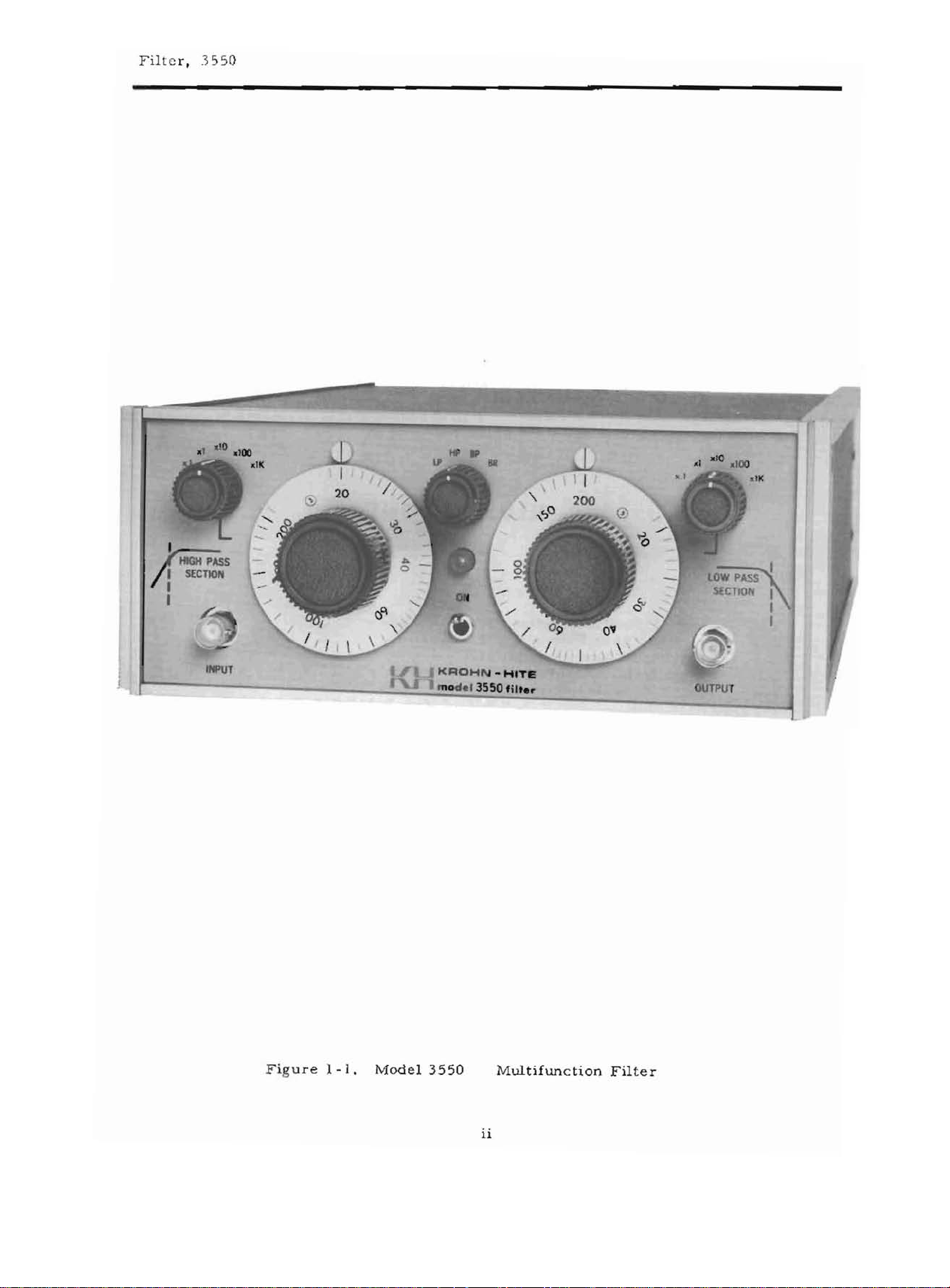
F ig u r e
1-1,
Model
3550
Multifunction
ii
Filter
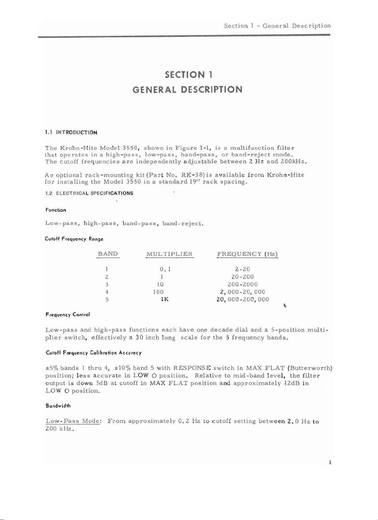
1.1 INTRODUCTION
Se
ctio
SECTION 1
GENERAL DESCRIPTION
n I -
General Descripti
on
T h e Kr oh n - Hi te
that
ope r a t e s
The
c ut o ff
A n
optional
(or
install
1.2 ELECTRICAL SPECIFICATIONS
Function
L o w
-pas
Cutoff
ing
s , high - pa s s , b and -p a s s ,
F
requenc
Model
in
a h
frequencie
rack
-m
th e
Model
y
Range
BAND
3550, shown
igh
-pass, low
s a r e
ounting
I
3550
2 I
3
4
5
F
requenc
y Can1
,01
i n F
-pass, band
independentl
kit
(P a r t No .
in a standard
band-
M U L T IP L IE R
O. 1 2 - 20
10 20 0
l Oa
lK
igu
re 1-1,
-pass, or
y a dj us ta b le
RK
- 38)
is availabl
19" r a c k
reject.
is a mu
bet
spacing
F
2,
RE
lti
func
tion
band
-reject
ween
000
2 H z and 2 0
e f r om Kroh n -Hit e
.
QUE
NC
Y (Hz )
200
20 -
-200
0
-20, 000
20 , 000 - 200, 000
filte
mode
\
r
.
0kHz
.
L ow - p a s s
li
e r switch
p
Cutoff
±50/0
bands
positio
output i s d o wn 3dB a t cu t o
L OW
Bandwidth
Low-Pass
and
high-pass
, effe ct i v e l y a 3 0 i
Frequency
n ; l e s s a c c ur a t e
0 p os i
Cal ibrc tion
1 t h r u 4,
tion.
Mode
: From a
Accu
±lO%
in
200 k Hz ,
functions
nch
'a cy
band
5 with
L OW 0 p
ff
in
MA
pproximate
ea
ch
have
lo n g
X F
scale
RESPONS
ositi
on .
LAT position
ly 0.2
one
decade
fo r
the 5freque n
E switch
Relativ
Hz to c u to
e t o m
a nd
dial
in
MA
id-
app
roximate
ff
setting bet
and
a 5-
position
cy
band
s .
X F LAT (B u t te r wo r th )
ba n d l ev e l,
l y .12.d B in
we en
2.
multi
the filter
°H z
to
-
Filter, 3550
High-Pass
z.
3 M H
Ban
d-Pass:
wi d th
p r
oduce
Mod
Both cut
(Butterwo
s a n
inserti
e : F r om cu to ff s e tting o f 2.0 Hz to 2 00 k Hz , to approx
rth
mid-band frequenc
Ban
d-Reject:
pass
ba nd t o app r o
sharp null can
freque
n c y, and t he L o w P a s s s e cti
justing both
Response
Choice
tion
selected
Attenuation
Nominal
Charocteristi
of
and L ow Q (da
by
24
d ials fo r
4 p ol e
mean!')
Slope
dB
Bot h
be obta
Butterworth
per octave
offs adjustable fro
response) both
on
loss
of 6 dB, with
y.
cutoff
f r eque
ximately 0.
in ed b y s
minim
cs
m p e d
um
respon
of a switch
In
c u t o
nci
es
adj us ta b
2 Hz ,
upper
etting the
on
to
r e s pon s e .
(Maxi
mally fia t
se) fortra n s i
on
the
rear
all
rn od e s
m 2 . 0 Hz t o 2
ff frequencies
the
3dB
po
le
fr om
passband
High Pa
half
ss
the
null
res
pon s e ) fo r fre que n cy d om a in op er a -
ent-fr
pa ne
l.
of ope
r a tion .
00
k Hz , F o r m in im um
a r e s et
int
s a t 0
2. 0 Hz
to
app
s ec t io n
fr e qu e n
to
c oinc id e.
.8 and]
to 200 k Hz .
r o
ximatel
to
about twice
cy,
e e tim e d o m ain
ima
tel y
ba
nd -
Th
is
. 2 5
times the
Lower
y 3
MHz
. A
the
null
and a lt e r n a te l y a
operati
on,
d-
Pa$S
Band Gain
Zero
db
+ 1
Maxi mum
Great
Input
Max
Max
Input
Output
Max
Attenuat
er
than
Character;
Volta
g e :
DC
Component:
Irnped
Characteri
Volta
ge : ±7V
Max Current:
Internal
Imp
db
in
ian
60
dB
stic
5
±7V
anc
e : 10
51iC5
± 15
ed an ce :
pass
peak
peak
rna
band.
to 2 MHz.
±lOOV.
Megohms
to 2 MHz.
peak.
50
ohms.
in
parallel
wit
h 50
pi.
Hum lind Hoi
Less
than
2
se
200
uv
,
except
400
uv
in
"BAN
D
RE
JECT"
rn
od e ,
Output
DC
Le
ve l
Stobi Iity
Section
1 -
General
Descript
ion
± l m y / oC t ± l
Front
Panel
Control
High
Pass
Sectio
Low
Pass
Function
P o w e r
Reor
Ponel
Re sp ons e
Gr ound
Sectio
Switch: LP,
ON
Switch
Control
Switc
Switch
DC L e ve l: P
L ine Switch:
Terminals
rnv
Zhr .
Somewhat
s
n : Hz d i a l a n d m
n : Hz d ialand
HP
s
h : M
AX
: C HASSIS,
ot
entio
m et
er.
115V
/230V.
g r e
ultip
multip
,
BP,
E R .
FLAT, LOW
FLOATI
NG .
ater
in
l i er swit c
lie
r s witc h .
Q.
BR
m od e .
h.
Front and r e
ar
pa nels , one E NC
r ec ept a cle w it h d e t
POWIIT
Henuirernants
105-125
Operating
occ
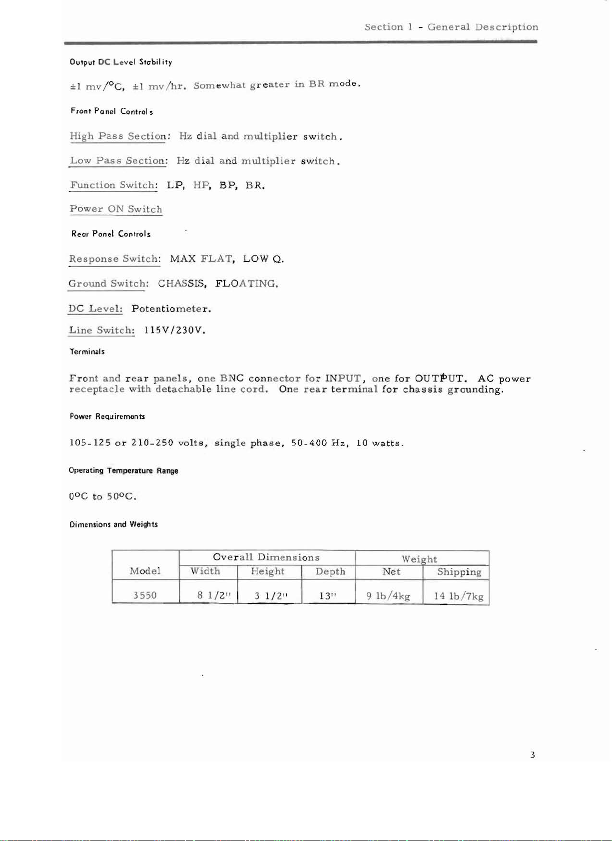
Dimensions
or
Temperature
to
50aC .
and
210-250
Range
Weights
Model
355
0 8 1/ 2"
acha
bl e l in e cord. On
volts,
sin
gle
Overa
Widt h
con
ne ct o r fo r INP U
e r ea r
phase,
ll
D im e n s io n s
50-400
Height
3 1/ 2"
termina l
Hz,
Dept
h
13 "
T,
10
on e
watts.
9
Ib/4kg
for
for cha
We i
Ne
t
OUTPUT.
ssi
s g r ou nd ing .
ht
hipping
S
14 Ib / 7kg
AC
power
3
F ilte r, 3 5 50
2.1
INITIAL
Thefilte r
mee
t s all
filter
Th
e M od e l
ve
ha
T
he
50 - 4 00 H z ,
r e
ar
theLIN
b e u se d. Wh e n th e
t
he230V
SETUP
is adjusted
specifications
is
shi
pped
complete
3550
s hould
oc c u rred
Filter may
pa nel, s el e ct s t
E s wit c h toth e I 15V po sitio
po
in s hipping
be
or
2 10 - 2 5 0 volts , 50- 400 H z. A I1 5 / 230 V LINE
sit
io n,and
OPE
and
checked
.
It
and
be
unpacked
.
op er ated f
he
filt
er's mode
fi
lte
r is to
r e
pla
SECTION
2
RATING INSI CIIONS
ca r eful
is
then
afte r unpacking is
Check
rom
c e thefu s e with a 1/ 16 ampe r e
be
an
op e r a
all
n . In t his
l y inour
ag e d
and
tested aga
ready for
ca r efull y
controls
A C p owe r sourc
of
operation, Wh
ted from
and
for
mod
230 VAC, move t
test
department
in
in s pect
freedom
e , a 1/ 8
ed for
e o f e
en the
before
use.
ithe
ampe
to
insure
shipmen
damage that ma
of
ope
ration
r 10 5-12 5 v olts ,
wi
t ch , locatedon the
AC
line
r e 5
he
slo
-bl
o t ype .
.
i s 11 5 V, m o
10-
blofu se
L I
NE switch t o
t.
t ha t
The
y
ITlUS
it
ve
t
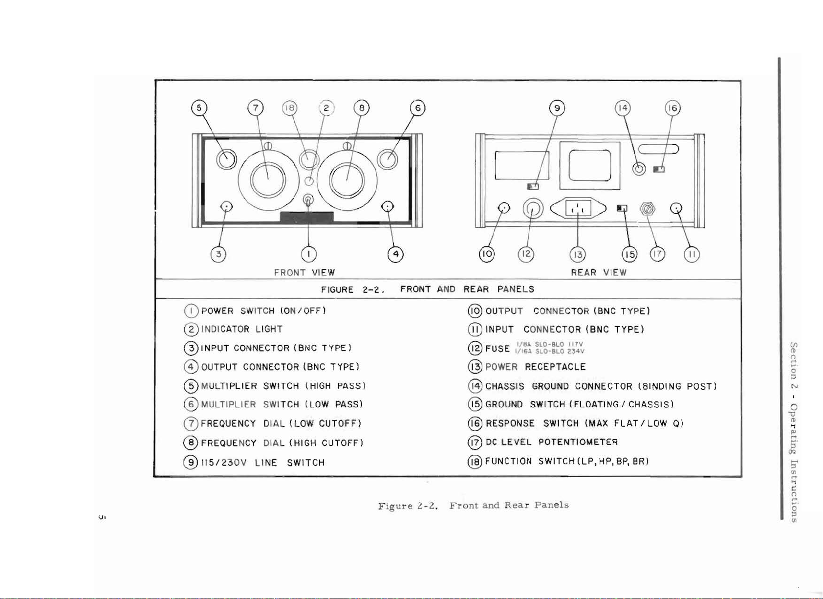
2.2 CONTROLS AND TERMINALS
2.2.1 Fro" I Ponel
T
he
funct
4
functio
ion
n s
witch
s : L o w P a ss (LP ),
in
the
(figure
top
Hig
2-2)
center
h P a s s (H P),
of the
front
panel
Band Pas
selects
s (B
on e of
P),
o r B a nd R ej e c t (B R ) .
fou
r fi
ltering
g
FRONT
CD
POWER SWITCH (ON IOFF )
® INDICATOR LI GHT
@INPUT
CONNECTOR
® OUTPUT CONNECTOR
® MULT I PL IER
® MULTIP
LIER
SWITCH
SWITCH
oFREQUENCY DIAL
® FREQUE NCY DIA L
® 115 / 23
VI
0V
LI
NE
VIEW
(BNC
(BNC
(HIGH
(LOW
(L
OW
(HIGH
SWITCH
FIGURE
TYPE)
TYPE)
PASS)
PASS)
CUTOFF)
CUTOFF)
2-2.
FRONT AND
F
igur
e 2 - 2. Front
REAR
REAR
PANE
LS
® OUTP UT CONNECTOR
@
INPUT
@
12
FUSE
@POWER
CONN
ECTOR
I/
BA
SLO-
BLO
1/ 16A SLO- BLO 23 4V
RECEPTACLE
!lT
VIEW
(BNC TYPE)
(BNC
V
TYPE)
@ CHASSIS GROUND CONNECTOR
@ GROUND SWITCH
@ RESPONSE SWITCH
@ DC
@
LEVEL
FUNCTION
and
Rea r
POTENTIOMETER
SWITCH
Panels
(FLOATING I CHASSIS)
(MAX
(LP,
FLAT
HP, BPt BR)
(BINDING
I LOW
0)
POST)
:.n
(1)
('l
,...
...
o
...
N
o
v
l't>
-t
PJ
...
...
::J
()Q
5'
til
...
....
c
('l
...
....
o
::l
t1l
.
.
F
ilter, 355
The
cuto
P a s s a nd o
T
he powe
0
ff
frequencies
ne for the LLl\\
r O N swi
tch
are
Pass
and
indicator li
se t
by dia
s ec ion
con t r ol s .
onnec
tors
fo r
s w itch
them
er permits
INPUT
in F
m
B NC C
2.2.2
Rear
Panel
The
R ES P O
t
he
Model
ad
ver
tent
and
disc
ju
stable potentiomet
elects 115
s
The
IN P U T a nd OUT P UT BNC co nn ec to r s a
bingin
A
fuse
g po st p
holder
SE
3 5 50 . T he G RO U. ' D swit
oper
ation, c o n nects
onne
cts
V r 2 30 V A C ope rat i o n .
rovides
l ab e led wit h the r e qu ir e d
and
provides
LOA
eans
for
th e chass
TI
se
panel.
l s
and
rn ul t i pl i e r s w itches, o ne fUI'
s.
g ht
in
the l ower cen
OUTPUT are
ch o
ice
be
twee
located
n M A X
c h, r e ce s s ed in the r e
is
to circuit grou
G . TheDC
L E V ELmultitur n s c r e wd rive r -ad-
ter
comp
in I he l owe r corners
FL
AT
and
ar
panel
nd
in t ne
tting of the ou tpu t D C level. The
gain occup
grounding the
fuse ratin
chassis
y t
g , is a
he
c or ne r s a nd th e
.
lso
mount
the
lete the fr on t
.
LO\
.\,'
0 r e
sp
to pr e v ent i n -
CHAS
SIS
pos it
LINE
ed
on
s w itch
the
l'
Hig
h
pane
on s e
ion
CHASSI
a r
l
of
S
2.3
OPERATING
2.3.1
2.3.2 Ma
2.3.3
section
2.3.4 T u r n
2.4 SPECI AL FUNCTIONS
Conn
Set
cont
PROCEDURE
ect
t he Mod
ke
c o nne cti on s to
the f u n ct i on s wi
ro l s t o t h e r eq u i r ed fr e qu en cy
ON
pu
\'.
,'er.
el 3550
If
sp
the out
cl
ipp ing w
to the
the
INP
tch
to th
e d e s i r e d m od e a nd the
th e inpu t s ig nal
e ci
fied
levels (
put c u r r e nt ex ce ed s ±15m A p e a
ill occu r .
UT
power
and
NOTE
7v
line.
O UT P U
ranges.
exceeds
pe ak, ± IOO
T.
the
m a x im um
High
vdc) or
P a s s and
if
Low Pas s
2.4.1 Narrow Bon
Nar
r owes t
pass
dposs
ban
d
in
the
quencie s equ al a s shown in
6
ba nd - pa s s
figu
r e
2-2,
mod
cu r v e
e i s obta
C. The
ined
by s e
tt
in g bot h c ut o ff
r e s ulting in se r ti on
fre-
loss is
 Loading...